A Model-Checking-Based Framework for Analyzing Ambient Assisted Living Solutions †


Abstract
1. Introduction
- A fall event occurring due to low pulse: In this case, if the fall sensor and the pulse monitoring sensor work independently of each other, no connection can be established between the two events, only an integrated solution would be able to indicate that the potential reason for the fall is in fact the person’s low pulse, which in turn may be critical for diagnosis (especially in case of patients having cardiac diseases).
- A high pulse detected during an exercise session: In case of such a scenario, the high pulse is absolutely normal, and hence no alarm should be raised. However, if the activity detection (in this case detecting an ’exercise session’) is not combined with pulse monitoring device, a false alarm will be triggered in the scenario.
- Simultaneous occurrence of fire and fall events: When both these events occur together, a safe mitigation of the scenario is achieved only when both these events are communicated to caregivers and firefighters, which is not guaranteed by independent systems working side by side. Assuming that the fire alarm communicated to the firefighters is verified for confirmation by a phone call to the user’s home, due to the inability of the elderly person to answer, the fire alarm may be deemed false and discarded, triggering a potential catastrophe [1,2].
2. Preliminaries
2.1. The Architecture Analysis and Design Language
2.2. Formal Notations and Tools
2.2.1. Timed Automata and Stochastic Timed Automata
2.2.2. UPPAAL and UPPAAL SMC
3. A Framework for Formal Analysis of AAL Systems: Proposed Methodology
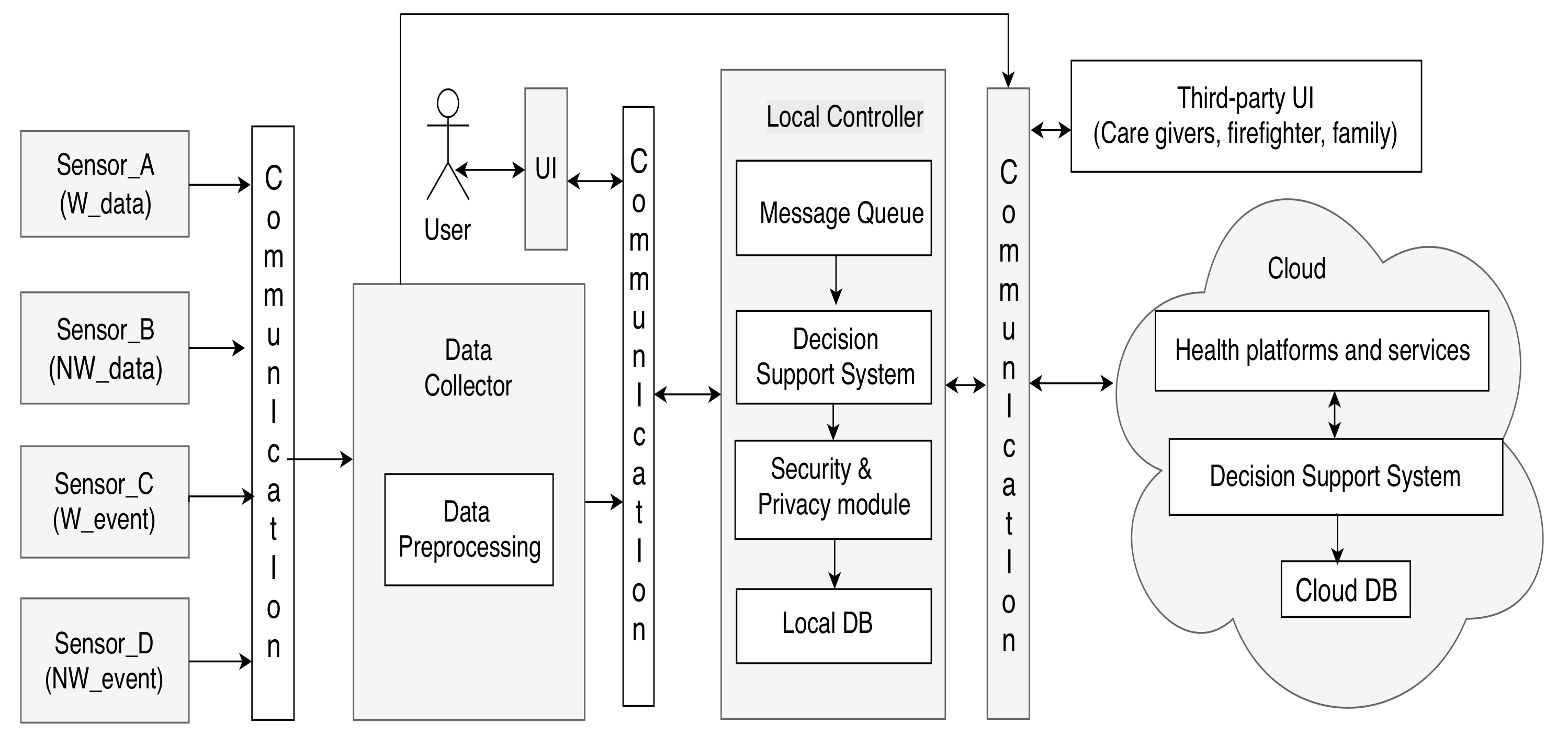
4. A Generic AAL System Architecture
- Wearable sensors that send information as data (W_data), e.g., sensors measuring health parameters like pulse, ECG, etc. They are represented by the Sensor_A category in Figure 2;
- Non-wearable sensors measuring ambient parameters and health parameters (NW_data), e.g., camera sensors, motion sensors, etc., represented by the Sensor_B category;
- Wearable sensors that detect events (W_event), e.g., fall sensors, marked as the Sensor_C category;
- Non-wearable sensors detecting events (NW_event), e.g., fire sensors, denoted by the Sensor_D category.
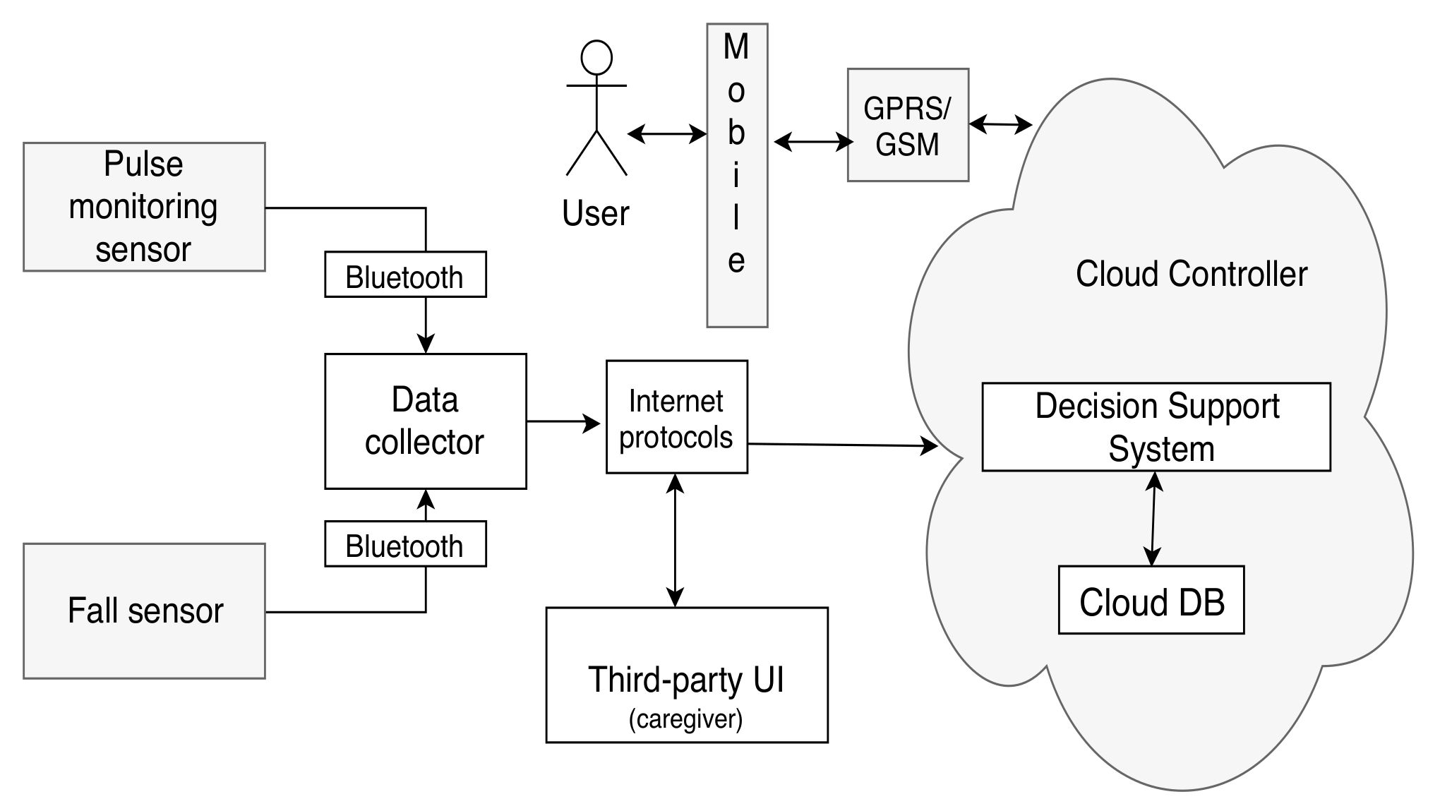
- Category 1: A minimal configuration—The minimum configuration architecture consists of the following modules: Two sensors (a fall sensor and a pulse monitoring sensor), a mobile phone UI, and cloud controller with a third-party UI and DSS system with a minimum context-space information including the health data (pulse and fall) and DA. The simplified DSS employs only RBR with fuzzy logic as AI techniques. The minimal configuration is shown in Figure 5.
- Category 2: An intermediate configuration—This instantiation (see Figure 6) is more complex than the previous one and it contains sensors belonging to all four types of the generic architecture (health monitoring sensors that detect pulse and blood pressure, smart home sensors that detect user movements, a wearable fall sensor, and a set of physical exercise monitoring sensors), as well as a local controller with inbuilt data collection functionality, which forwards the data to the cloud controller. The cloud controller has a DSS with context modeling, fuzzy logic, and RBR.
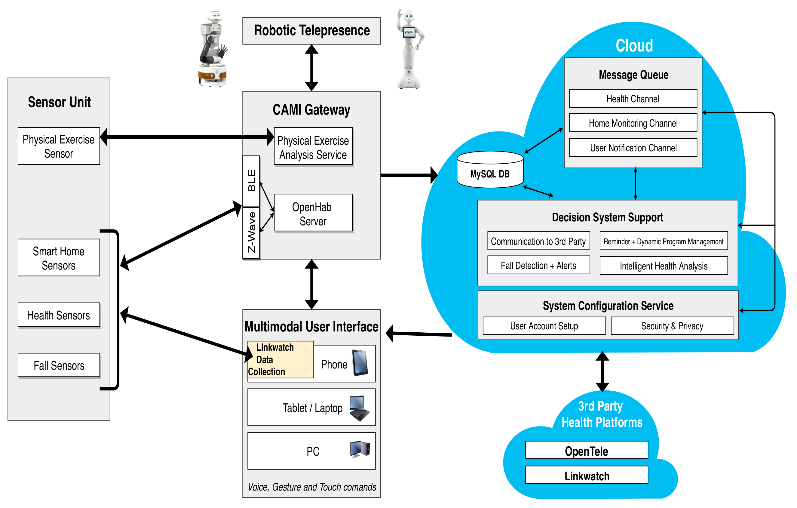
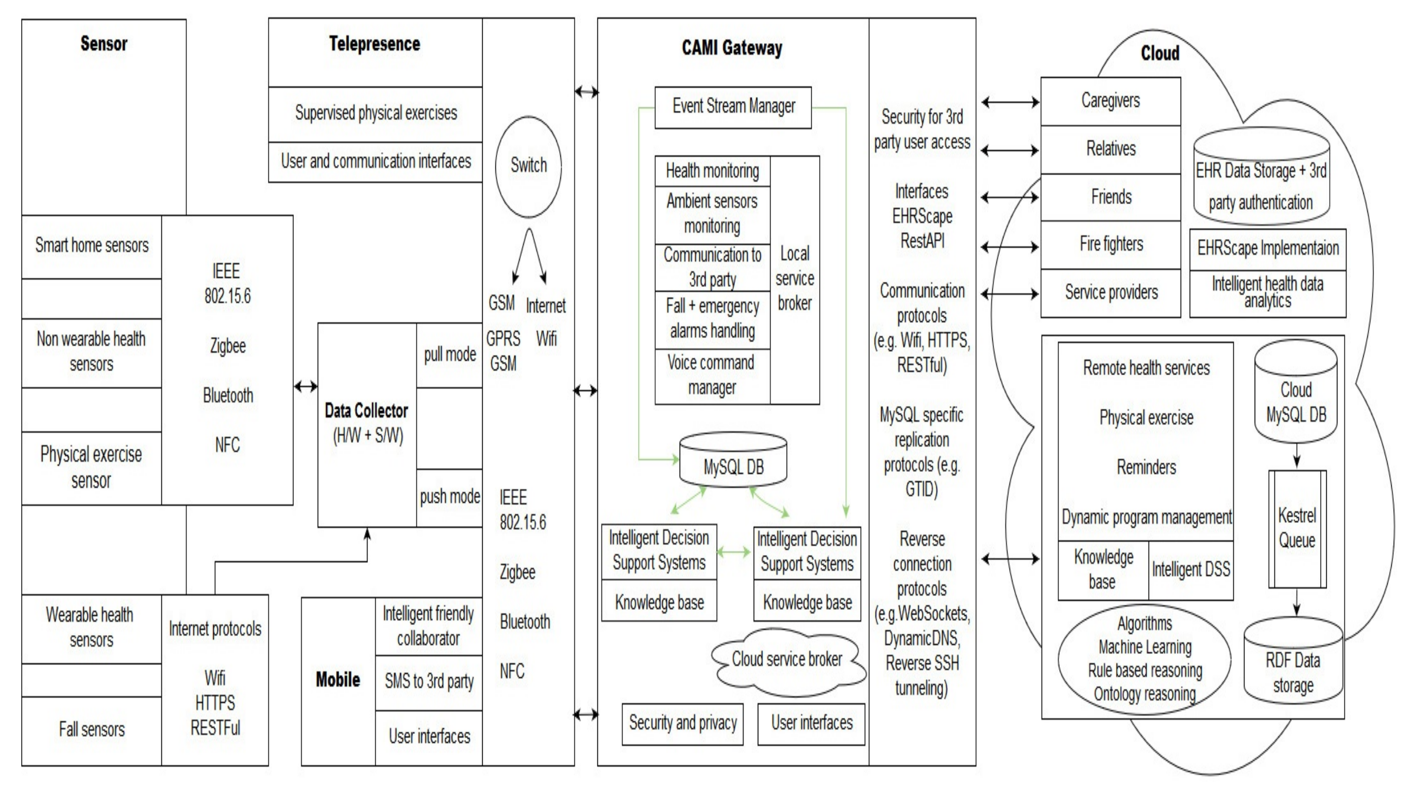
- Category 3: A complex configuration—In this category, we present the most complex version, the CAMI AAL architecture [2] derived from our generic model, and represented in Figure 7. The latter supports various sensors (e.g., a multitude of health and home monitoring sensors like the A&D UA-651 BLE blood pressure sensor [20], Fibaro temperature and motion sensor FGMS-001 [21], Fitbit bracelet [22], Vibby fall detection sensor [23], etc.), data collector, local controller (EXYS9200-SNG [24] referred as CAMI gateway), the CAMI cloud, and third party health platforms like Open Tele [25,26]. There is a set of user interfaces (UI) in CAMI, including robotic platforms (TIAGo [27] and Pepper [28]), mobile phone and vocal interface to facilitate the interaction with the elderly user. There is also a local backup of DSS in the CAMI gateway apart from the cloud. The communication between various modules can employ a variety of communication protocols, for instance, Bluetooth, Zigbee, Wifi, etc. The local processor is called the CAMI gateway and is responsible for all critical functionalities. The Message Queue is implemented by Rabbit MQ Message Broker [29]. The DSS is complex and employs context modeling, fuzzy logic, RBR and CBR. There are also redundant copies of DSS in the local controller and cloud controller.
4.1. Use Case Scenarios and System Requirements
- Scenario 1—Assistance for detecting health parameter deviations: Jim has sudden pulse variations detected by the pulse monitoring sensor, which is critical for cardiac patients. If the pulse is low, the DSS alerts the caregiver of a low pulse. If the pulse is high and the user is currently exercising, this is considered as normal, and if not, it sends an alert to the caregiver.
- Scenario 2—Fall detection: Jim falls heavily while exercising, the fall sensors detect the fall and the system immediately notifies the caregiver of the fall event.
- Scenario 3—Home-monitoring functionalities: Jim forgets to switch off the cooker after cooking his dinner, which results in a fire in the house. The fire detection sensor of CAMI detects the fire and the system alerts the firefighters of the fire incident in Jim’s house.
- Scenario 4—Combining various functionalities in case of multiple events occurring together: Jim is cooking his breakfast. He suddenly feels dizzy and falls. The gas-based cooker is still on, and eventually starts a fire in Jim’s house. In this case, the CAMI system detects the simultaneously occurring events, and alerts the firefighter and caregiver of both the events. As a result, the firefighters and caregivers can immediately start the rescue without waiting for alarm confirmations, avoiding potentially dangerous consequences [1]. Further, if there are any health parameter variations detected for Jim along with the fall (for instance, a low pulse), the fall event can be associated with the low pulse, and the caregiver notified accordingly, which can help in further diagnosis.
4.2. Requirements of the Minimal Architecture Model (Category 1):
- R1: If a high pulse is detected by the pulse sensor and the elderly user’s DA is not exercising, then the DSS sends a notification to caregiver within 20 s. This requirement relates to Scenario 1
- R2: If a fall is detected by the fall sensor, then the DSS sends a notification to caregiver within 20 s. It is associated with Scenario 2.
4.3. Requirements of the CAMI Architecture (Category 3):
- R1: If the fire sensor detects a fire, then the DSS sends a notification to the firefighters, within 20 s. This requirement corresponds to Scenario 3.
- R2: If a fall is detected by the wearable or the camera sensor, then the DSS sends a notification to the caregiver, within 20 s. This requirement relates to Scenario 2.
- R3: If fire and fall are detected simultaneously by the respective sensors, then the DSS should detect the presence of the simultaneous events and send notifications to both the firefighters and the caregiver indicating the presence of both events, within 20 s. This relates to Scenario 4.
- R4: If there is a pulse data deviation indicating high pulse, the DA is “not exercising”, and the user has a disease history of a cardiac patient, then the DSS sends a notification to the caregiver, within 20 s. This relates to Scenario 1.
- R5: The decisions taken by the local DSS are updated in the cloud DSS such that they are eventually synchronized. This requirement relates to the data-consistency requirement of CAMI.
- R6: If the local DSS fails, then the cloud DSS eventually becomes active. It corresponds to the fault-tolerance aspect of the CAMI system.
5. System Modeling in AADL
- Atomic Components (AC): Components that do not have hierarchy in terms of sub-components with port interfaces, but might contain sub-components without port interfaces.
- Composite Components (CC): Hierarchical components that contain sub-components with and without interfaces. For example, data is a sub-component without interface and it can be part of an AC or CC hierarchy.
5.1. AAL Atomic Components
| Listing 1: An excerpt from the RBR component in AADL for CAMI. |
 |
5.2. AAL Composite Components:
| Listing 2: An excerpt from the DSS component in AADL for CAMI. |
 |
6. Semantics of AAL-Relevant AADL Components
6.1. Definition of AADL Components for AAL
- is defined as a tuple: , where:
- -
- = ∪, where , represent the sets of and respectively, and , ∈ {-, -, --};
- -
- , where , , represent flow sources, flow paths and flow sinks respectively. Let be a function that associates certain to with , be a function that associates and an input and an output to a flow, and be a function that associates certain to , with . For instance, in our AAL architecture, we can define for fall events by defining the output port of the fall sensor as , the input port of the cloud DSS as , and the input and output ports of all the intermediate components defining the Flow;
- -
- is the set of associated properties of the component, like , , , - , etc. [12]. In this work, we only consider a subset of , - , and - , that are represented as follows: } where and represent the period and execution-time of the component, respectively, , ∈ , (The dispatch protocol property of a thread determines when the thread is executed. A periodic thread is activated at time intervals of the specified period T; and an aperiodic thread is activated when an event arrives at a port of the thread.), where P represents a Periodic and represents an Aperiodic protocol, and - , and - represent the set of user-defined properties used for specifying the occurrence distribution of aperiodic events and failure recovery, respectively.
- is defined as , where:
- -
- represents the set of sub-components of the system with port interfaces () and without port interfaces (), i.e., ;
- -
- denotes the set of Prototypes used to define via , a function that associates to a , respectively;
- -
- represents the set of connections. is a function that assigns to ;
- -
- is the mode state machine that is modeled by a tuple, as follows: , where is the set of states, and is the transition relation (with being the set of events, such that -, -). We write as short for , where , and .The set of is defined with respect to , if present;
- -
- are the flow implementations, represented as ;
- -
- represents the set of end-to-end flows as complete flow paths from a starting to the final , respectively.
- The error annex is defined as the tuple: , where:
- -
- denotes the error flows, , where describes error propagations, and , , represents error sources, error paths, and error sinks, respectively; is a function that associates certain output ports with error sources, is a function that associates input and output ports via , is a function that assigns certain input ports as error sinks;
- -
- represents error behavior, , where represents the set of error states, denotes an error transition relation, , with , the set of error events. For a CC, the error behavior is represented as (error-model for a CC) with respect to the failure of its . Let and be two error states, , , and the transition between them due to an error event , then .We represent the initial state as . is a function that associates input and output ports to error propagations;
- -
- denotes the error properties. In our work, we focus only on two error properties: Duration distribution(), and Occurrence distribution (), which aid in our error analysis, thus .
- The Behaviour Annex, is defined as: , where , , represent the set of variables, and the states of , respectively and is a BA transition relation. Let and be two states of , , and the transition between them, , with being the set of data subcomponents. We denote by the initial state of a BA path.
- , where = }, , where , ,
- , where = , , where , . A CC represents the system-level view of the architecture.
- , with:
- -
- =∪, and , ∈ { --},
- -
- = ,
- -
- = {
- ={}
- = {}.
- ={, , }, where:
- -
- =∪, and , ∈ {--},
- -
- = ,
- -
- = {.
- ={, , , }, where:
- -
- = ,
- -
- =,
- -
- ={, , , },
- -
- ={}.
- .
6.2. Formal Encoding of AADL Components as NSTA
6.2.1. Formal Encoding of AC
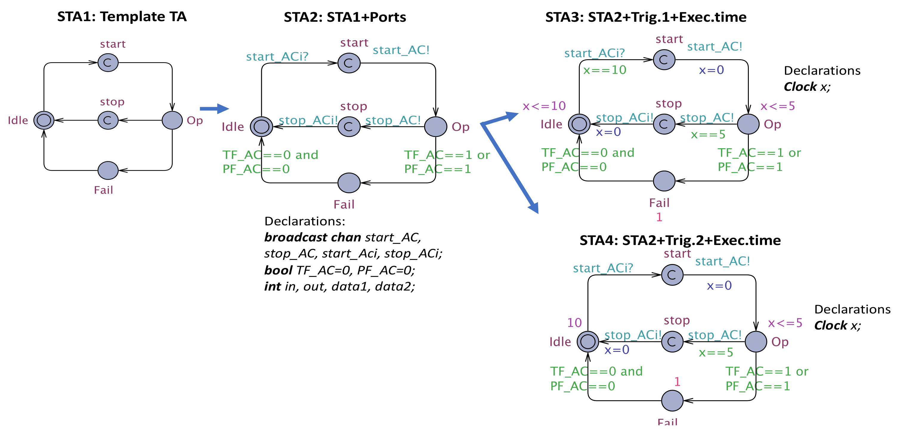
- The AC is defined according to a template STA (see Figure 8) with , , corresponds to the Operational state of the RBR, , represent the locations to initiate the synchronizations with and . This template is annotated with the following information:
- -
- , where and represent the set of output and input ports -, -, --, respectively, and the Boolean variables, , represent the error events associated with the transient failure and permanent failure of AC, plus the variable associated with ;
- -
- is the set of clocks that models the period and execution time of AC;
- -
- , where A is the set of synchronization channels associated with input-output ports --, -, that is, channels , and the synchronization channels for the interface of the corresponding CC, that is, and the reset actions on x;
- -
- , where E is defined by the template populated with A and guards that ensure the correctness of transitions.
- -
- =, if the dispatch protocol associated with AC is periodic, and , where and represent the period and execution-time of AC;
- -
- , and , where represents the occurrence distribution of aperiodic event (if the dispatch protocol associated with AC is aperiodic), and represents the probability of leaving location ;
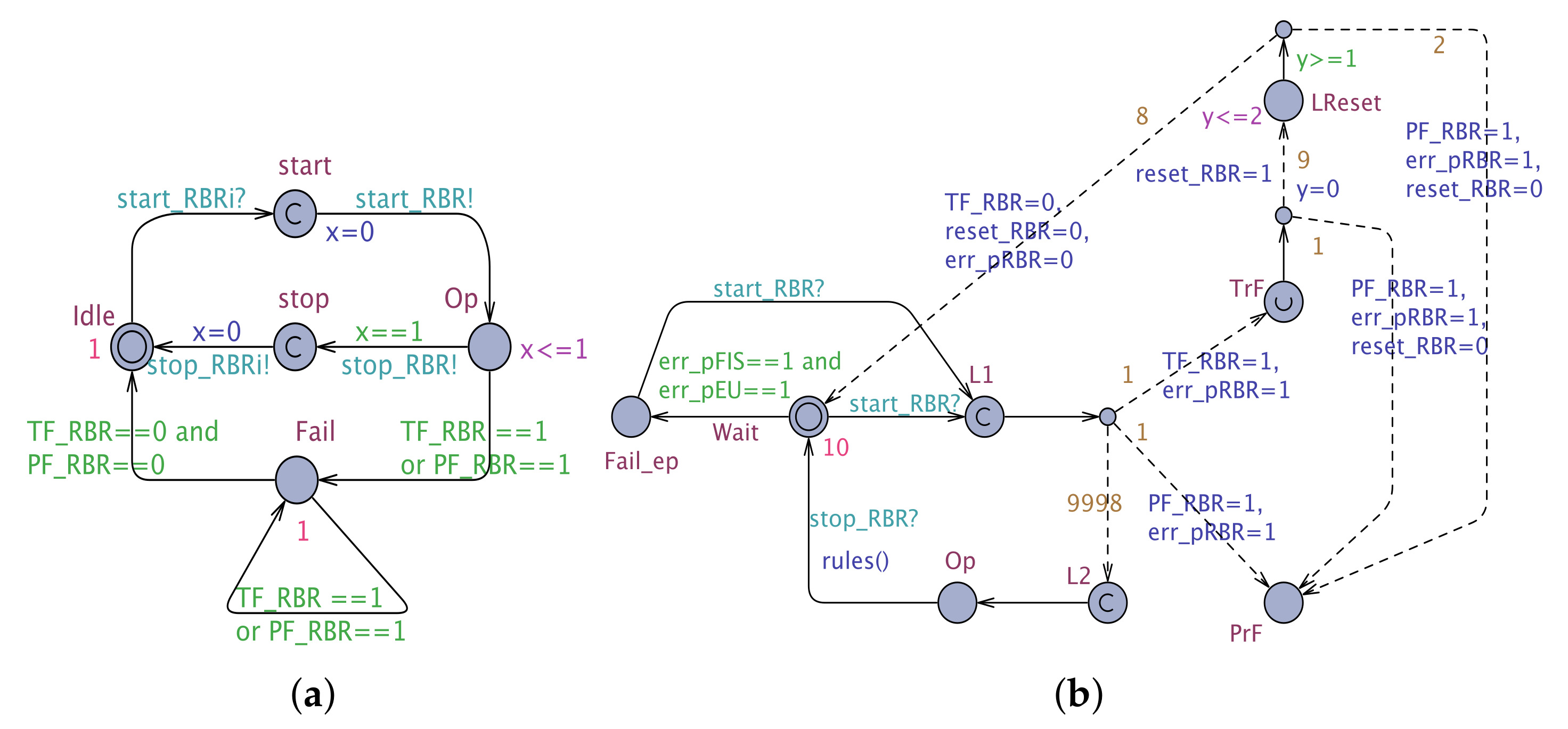
- The AC is created in a similar way with:
- -
- , where L comprises the set of states in EA and BA (Wait, Operational (Op), Transient Failure (TrF), Permanent Failure (PrF), Failed due to error propagation (Fail_ep), and reset location (LReset), plus additional committed locations that ensure that receiving is deterministic in UPPAAL SMC;
- -
- , where A is composed of the actions defined in BA and EA (action ), plus the synchronizations channels to concord with (), and the reset of clock y;
- -
- , where V consists of the set of error events defined in the EA, that is, PF_AC: Permanent Failure of AC, TF_AC: Transient Failure of AC, reset_AC: Reset of AC, err_pAC: error propagation of AC;
- -
- is the clock that measures the time elapsed for reset action of a particular component;
- -
- , where E consists of the transitions in EA, BA and those between and ;
- -
- = ;
- -
- , that is the occurrence-distribution of ;
- -
- , , where , are defined according to the occurrence-distribution of the error events.□
6.2.2. Formal Encoding of CC
- The CC is defined by formally encoding , as follows:
- -
- , where L contains one location for each sub-component defined by SC, one additional location for each sub-component that ensures the correct synchronization, location to model the component failure, and to model the initial location;
- -
- E is defined according to . For each connection in , we define two edges, and , where l, l’ are locations created based on the sub-components for which the connections are defined, and is a location created for synchronization;
- -
- , where and represent the set of output and input port variables -, -, --, respectively, and the Boolean variables, , represent the error events associated with the transient failure and permanent failure of CC, plus the variable associated with ;
- -
- if ;
- -
- A is defined based on the updates defined by , the updates defined by , the synchronizations defined by , the synchronization with , , and in case C is not void, we add the clock reset of the clock(s) in C;
- -
- = if ;
- -
- , where and is defined by .
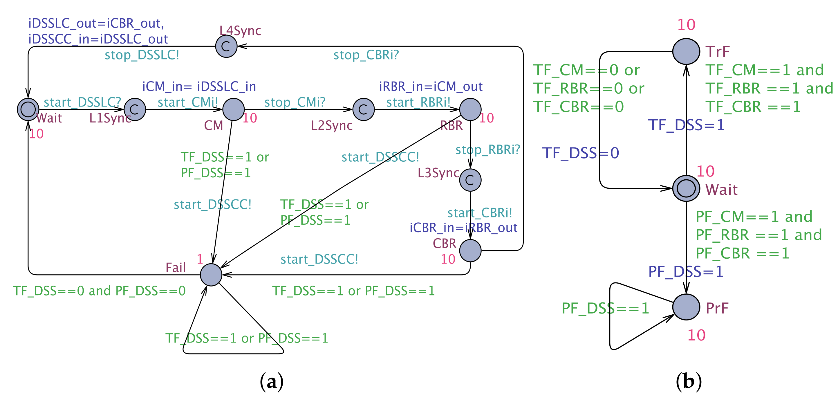
- CC is defined as follows:
- -
- , , where is the set of states of EA;
- -
- ;
- -
- ;
- -
- V is represented by the global variables defined in ;
- -
- ;
- -
- , where and is defined by .
All the other CC elements are transformed based on the encoding EA of AC.
- The is formally represented as a tuple, where:
- -
- ,
- -
- -
- -
- -
- -
- =
- -
- , , given by
- is defined in a similar way:
- -
- -
- =,=, =, =, =, y=
- -
- -
- -
- -
- -
- , given by
- -
- , , assigned by
- The tuple elements of are as follows:
- -
- ,
- -
- -
- -
- -
- =10, =10, =10, =10, =1
- has the following syntactic elements:
- -
- },
- -
- -
- -
- -
7. AAL Architecture Verification and Discussion
7.1. Exhaustive Verification of the Minimum Configuration Using UPPAAL
7.2. Statistical Verification of the CAMI architecture Using UPPAAL SMC
7.3. Comparison of the Proposed Approach With the Model-Checker PRISM
| Listing 3: An excerpt of the PRISM model of an RBR |
 |
8. Discussion
9. Related Work
- Agent-based architectures: These are the most commonly used architectures for AAL applications, based of their flexibility, autonomy, adaptability, better response, and service continuity due to their distributed nature. Some examples of health-care frameworks that rely on a distributed agent architecture are described in the literature [34,40]. However, the agent-based architectures have some drawbacks: (i) restricted communication protocols for agent communication and the delay overhead in taking a collective decision; and (ii) maintaining the consistency.
- Cloud-based AAL solutions: This category includes AAL solutions that leverage the potential of cloud computing for context modeling, intelligent decision making, and data-storage usage. Our architecture follows the design paradigms of Cloud-based AAL solutions, where the cloud is utilized for intelligent, context-aware decision making, also as a data store, and it is also augmented with local processing schemes to guarantee real-time properties. In many situations, cloud services cannot guarantee hard-real time properties, the cloud being a backup that gets activated only when the primary one has failed.
10. Conclusions and Future Work
Author Contributions
Funding
Conflicts of Interest
References
- Kunnappilly, A.; Seceleanu, C.; Lindén, M. Do We Need an Integrated Framework for Ambient Assisted Living? In Proceedigns of the Ubiquitous Computing and Ambient Intelligence: 10th International Conference, UCAmI 2016, San Bartolomé de Tirajana, Gran Canaria, Spain, 29 November–2 December 2016; Springer: Cham, Switzerland, 2016; Part II 10, pp. 52–63. [Google Scholar]
- Kunnappilly, A.; Sorici, A.; Awada, I.A.; Mocanu, I.; Seceleanu, C.; Florea, A.M. A Novel Integrated Architecture for Ambient Assisted Living Systems. In Proceedings of the 2017 IEEE 41st Annual Computer Software and Applications Conference (COMPSAC), Turin, Italy, 4–8 July 2017; Volume 1, pp. 465–472. [Google Scholar]
- Augusto, J.C.; Nugent, C.D. The use of temporal reasoning and management of complex events in smart homes. In Proceedings of the 16th European Conference on Artificial Intelligence, Valencia, Spain, 22–27 August 2004; IOS Press: Amsterdam, The Netherlands, 2004; pp. 778–782. [Google Scholar]
- Rodrigues, G.N.; Alves, V.; Silveira, R.; Laranjeira, L.A. Dependability analysis in the ambient assisted living domain: An exploratory case study. J. Syst. Softw. 2012, 85, 112–131. [Google Scholar] [CrossRef]
- Kunnappilly, A.; Marinescu, R.; Seceleanu, C. Assuring intelligent ambient assisted living solutions by statistical model checking. In International Symposium on Leveraging Applications of Formal Methods; Springer: Cham, Switzerland, 2018; pp. 457–476. [Google Scholar]
- Bengtsson, J.; Larsen, K.; Larsson, F.; Pettersson, P.; Yi, W. UPPAAL—A tool suite for automatic verification of real-time systems. In International Hybrid Systems Workshop; Springer: Berlin/Heidelberg, Germany, 1995; pp. 232–243. [Google Scholar]
- David, A.; Larsen, K.G.; Legay, A.; Mikučionis, M.; Poulsen, D.B. Uppaal SMC tutorial. Int. J. Softw. Tools Technol. Transf. 2015, 17, 397–415. [Google Scholar] [CrossRef]
- Kwiatkowska, M.; Norman, G.; Parker, D. PRISM: Probabilistic symbolic model checker. In International Conference on Modelling Techniques and Tools for Computer Performance Evaluation; Springer: Berlin/Heidelberg, Germany, 2002; pp. 200–204. [Google Scholar]
- Feiler, P.H.; Lewis, B.; Vestal, S.; Colbert, E. An overview of the SAE architecture analysis & design language (AADL) standard: A basis for model-based architecture-driven embedded systems engineering. In Architecture Description Languages; Springer: Boston, MA, USA, 2005; pp. 3–15. [Google Scholar]
- Frana, R.; Bodeveix, J.P.; Filali, M.; Rolland, J.F. The AADL behaviour annex–experiments and roadmap. In Proceedings of the 12th IEEE International Conference on Engineering Complex Computer Systems, Auckland, New Zealand, 11–14 July 2007; pp. 377–382. [Google Scholar]
- Delange, J.; Feiler, P. Architecture fault modeling with the AADL error-model annex. In Proceedings of the 2014 40th EUROMICRO Conference on Software Engineering and Advanced Applications (SEAA), Verona, Italy, 27–29 August 2014; pp. 361–368. [Google Scholar]
- Feiler, P.H.; Gluch, D.P. Model-Based Engineering with AADL: An Introduction to the SAE Architecture Analysis & Design Language; Addison-Wesley: Boston, MA, USA, 2012. [Google Scholar]
- Larsen, K.G.; Pettersson, P.; Yi, W. UPPAAL in a nutshell. Int. J. Softw. Tools Technol. Transf. 1997, 1, 134–152. [Google Scholar] [CrossRef]
- Alur, R.; Courcoubetis, C.; Dill, D. Model-checking in dense real-time. Inf. Comput. 1993, 104, 2–34. [Google Scholar] [CrossRef]
- Alur, R.; Courcoubetis, C.; Dill, D. Model-checking for real-time systems. In Proceedings of the 1990 Fifth Annual IEEE Symposium on Logic in Computer Science, Philadelphia, PA, USA, 4–7 June 1990; pp. 414–425. [Google Scholar]
- Bulychev, P.E.; David, A.; Larsen, K.G.; Legay, A.; Li, G.; Poulsen, D.B. Rewrite-Based Statistical Model Checking of WMTL. RV 2012, 7687, 260–275. [Google Scholar]
- The Architecture Analysis & Design Language (AADL): An Introduction. Available online: https://people.cs.clemson.edu/~johnmc/courses/cpsc875/resources/06tn011.pdf (accessed on 19 November 2019).
- Zhou, F.; Jiao, J.R.; Chen, S.; Zhang, D. A case-driven ambient intelligence system for elderly in-home assistance applications. IEEE Trans. Syst. Man Cybern. Part C (Appl. Rev.) 2011, 41, 179–189. [Google Scholar] [CrossRef]
- Medjahed, H.; Istrate, D.; Boudy, J.; Dorizzi, B. Human activities of daily living recognition using fuzzy logic for elderly home monitoring. In Proceedings of the 2009 IEEE International Conference on Fuzzy Systems, Jeju Island, Korea, 20–24 August 2009; pp. 2001–2006. [Google Scholar]
- UA651 BP Sensor. Available online: http://www.andmedical.com.au/products-service/value-ua-651 (accessed on 16 March 2019).
- Fibaro motion sensor. Available online: https://manuals.fibaro.com/content/manuals/en/FGMS-001/FGMS-001-EN-T-v2.0.pdf (accessed on 16 March 2019).
- Fitbit. Available online: https://www.fitbit.com/se/home (accessed on 16 March 2019).
- Vibby Fall Detection Sensors. Available online: http://www.vitalbase.co.uk (accessed on 16 March 2019).
- CAMI Gateway. Available online: https://eclexys.com/wp-content/uploads/2019/01/Exys9200-SNG-Brochure.pdf (accessed on 16 March 2019).
- OpenTele. Available online: https://www.opentelehealth.com (accessed on 15 January 2018).
- Linkwatch. Available online: https://www.linkwatch.se (accessed on 15 January 2018).
- TIAGo Robotic Platform. Available online: http://tiago.pal-robotics.com (accessed on 16 March 2019).
- Pepper Robot. Available online: https://www.softbankrobotics.com/emea/en/pepper (accessed on 16 March 2019).
- Rabbit MQ Message Broker. Available online: https://www.rabbitmq.com (accessed on 16 March 2019).
- Kunnappilly, A.; Cai, S.; Marinescu, R.; Seceleanu, C. Architecture Modelling and Formal Analysis of Intelligent Multi-Agent Systems. In Proceedings of the 14th International Conference on Evaluation of Novel Approaches to Software Engineering, Heraklion, Crete, Greece, 4–5 May 2019. [Google Scholar]
- OSATE—Open Source AADL Test Environment. Available online: http://osate.github.io/ (accessed on 15 May 2018).
- Li, R.; Lu, B.; McDonald-Maier, K.D. Cognitive assisted living ambient system: A survey. Digit. Commun. Netw. 2015, 1, 229–252. [Google Scholar] [CrossRef]
- Rashidi, P.; Mihailidis, A. A survey on ambient-assisted living tools for older adults. IEEE J. Biomed. Health Inform. 2013, 17, 579–590. [Google Scholar] [CrossRef] [PubMed]
- De Paz, J.; Rodríguez, S.; Bajo, J.; Corchado, J.; Corchado, E. OVACARE: A multi-agent system for assistance and health care. In Knowledge-Based and Intelligent Information and Engineering Systems; Springer: Berlin/Heidelberg, Germany, 2010; pp. 318–327. [Google Scholar]
- Isern, D.; Sánchez, D.; Moreno, A. Agents applied in health care: A review. Int. J. Med Inform. 2010, 79, 145–166. [Google Scholar] [CrossRef] [PubMed]
- Nealon, J.; Moreno, A. Agent-based applications in health care. In Applications of Software Agent Technology in the Health Care Domain; Birkhäuser: Basel, Switzerland, 2003; pp. 3–18. [Google Scholar]
- Ahmed, M.U.; Björkman, M.; Lindén, M. A generic system-level framework for self-serve health monitoring system through internet of things (iot). Stud. Health Technol. Inform. 2015, 211, 305–307. [Google Scholar] [PubMed]
- Forkan, A.; Khalil, I.; Tari, Z. CoCaMAAL: A cloud-oriented context-aware middleware in ambient assisted living. Future Gener. Comput. Syst. 2014, 35, 114–127. [Google Scholar] [CrossRef]
- Dohr, A.; Modre-Osprian, R.; Drobics, M.; Hayn, D.; Schreier, G. The Internet of Things for Ambient Assisted Living. ITNG 2010, 10, 804–809. [Google Scholar]
- Tapia, D.I.; Rodrıguez, S.; Corchado, J.M. A distributed ambient intelligence based multi-agent system for Alzheimer health care. In Pervasive Computing; Springer: London, UK, 2009; pp. 181–199. [Google Scholar]
- Parente, G.; Nugent, C.D.; Hong, X.; Donnelly, M.P.; Chen, L.; Vicario, E. Formal modeling techniques for ambient assisted living. Ageing Int. 2011, 36, 192–216. [Google Scholar] [CrossRef]
- Magherini, T.; Fantechi, A.; Nugent, C.D.; Vicario, E. Using temporal logic and model checking in automated recognition of human activities for ambient-assisted living. IEEE Trans. Hum.-Mach. Syst. 2013, 43, 509–521. [Google Scholar] [CrossRef]
- Liu, Y.; Gui, L.; Liu, Y. MDP-based reliability analysis of an ambient assisted living system. In International Symposium on Formal Methods; Springer: Cham, Switzerland, 2014; pp. 688–702. [Google Scholar]
- Besnard, L.; Gautier, T.; Le Guernic, P.; Guy, C.; Talpin, J.P.; Larson, B.; Borde, E. Formal semantics of behavior specifications in the architecture analysis and design language standard. In Cyber-Physical System Design from an Architecture Analysis Viewpoint; Springer: Cham, Switzerland, 2017; pp. 53–79. [Google Scholar]
- Hamdane, M.E.; Chaoui, A.; Strecker, M. From AADL to timed automaton-A verification approach. Int. J. Softw. Eng. Appl. 2013, 7. [Google Scholar]
- Johnsen, A.; Lundqvist, K.; Pettersson, P.; Jaradat, O. Automated verification of AADL-specifications using UPPAAL. In Proceedings of the 2012 IEEE 14th International Symposium on High-Assurance Systems Engineering (HASE), Omaha, NE, USA, 25–27 October 2012; pp. 130–138. [Google Scholar]
- Bruintjes, H.; Katoen, J.P.; Lesens, D. A statistical approach for timed reachability in AADL models. In Proceedings of the 45th Annual IEEE/IFIP International Conference on Dependable Systems and Networks (DSN), Rio de Janeiro, Brazil, 22–25 June 2015; pp. 81–88. [Google Scholar]
- Bao, Y.; Chen, M.; Zhu, Q.; Wei, T.; Mallet, F.; Zhou, T. Quantitative performance evaluation of uncertainty-aware hybrid AADL designs using statistical model checking. IEEE Trans. Comput.-Aided Des. Integr. Circuits Syst. 2017, 36, 1989–2002. [Google Scholar] [CrossRef]


| REquation | Query | Result |
|---|---|---|
| R1 | ) | Pass |
| Pass | ||
| R2 | ) | Pass |
| Pass |
| REquation | Query | Result |
|---|---|---|
| R1 | ) | Fail |
| REquation | Query | Result | Runs |
|---|---|---|---|
| R1 | and | Pr [0.99975,1] confidence 0.998 | 3868 |
| Pr [0.99975,1] confidence 0.998 | 4901 | ||
| R2 | or | Pr [0.99975,1] confidence 0.998 | 3868 |
| Pr [0.99975,1] confidence 0.998 | 4901 | ||
| R3 | or and | Pr [0.99975,1] confidence 0.998 | 3868 |
and | Pr [0.99975,1] confidence 0.998 | 7905 | |
| R4 | and | Pr [0.99975,1] confidence 0.998 | 3868 |
| Pr [0.99975,1] confidence 0.998 | 3868 | ||
| R5 | Pr [0.99975,1] confidence 0.998 | 3868 | |
| Pr [0.99975,1] confidence 0.998 | 5777 | ||
| R6 | Pr [0.99975,1] confidence 0.998 | 3868 | |
| Pr [0.01,0.04] confidence 0.998 | 2885 |
| REquation | Query | Result | Time (s) |
|---|---|---|---|
| R1 | [l] | satisfied | 2001.7 |
| R2 | [l] | satisfied | 2001.7 |
| R3 | [l] | satisfied | 3500.13 |
© 2019 by the authors. Licensee MDPI, Basel, Switzerland. This article is an open access article distributed under the terms and conditions of the Creative Commons Attribution (CC BY) license (http://creativecommons.org/licenses/by/4.0/).
Share and Cite
Kunnappilly, A.; Marinescu, R.; Seceleanu, C. A Model-Checking-Based Framework for Analyzing Ambient Assisted Living Solutions. Sensors 2019, 19, 5057. https://doi.org/10.3390/s19225057
Kunnappilly A, Marinescu R, Seceleanu C. A Model-Checking-Based Framework for Analyzing Ambient Assisted Living Solutions. Sensors. 2019; 19(22):5057. https://doi.org/10.3390/s19225057
Chicago/Turabian StyleKunnappilly, Ashalatha, Raluca Marinescu, and Cristina Seceleanu. 2019. "A Model-Checking-Based Framework for Analyzing Ambient Assisted Living Solutions" Sensors 19, no. 22: 5057. https://doi.org/10.3390/s19225057
APA StyleKunnappilly, A., Marinescu, R., & Seceleanu, C. (2019). A Model-Checking-Based Framework for Analyzing Ambient Assisted Living Solutions. Sensors, 19(22), 5057. https://doi.org/10.3390/s19225057