Real-Time Underwater StereoFusion

 , and
, and 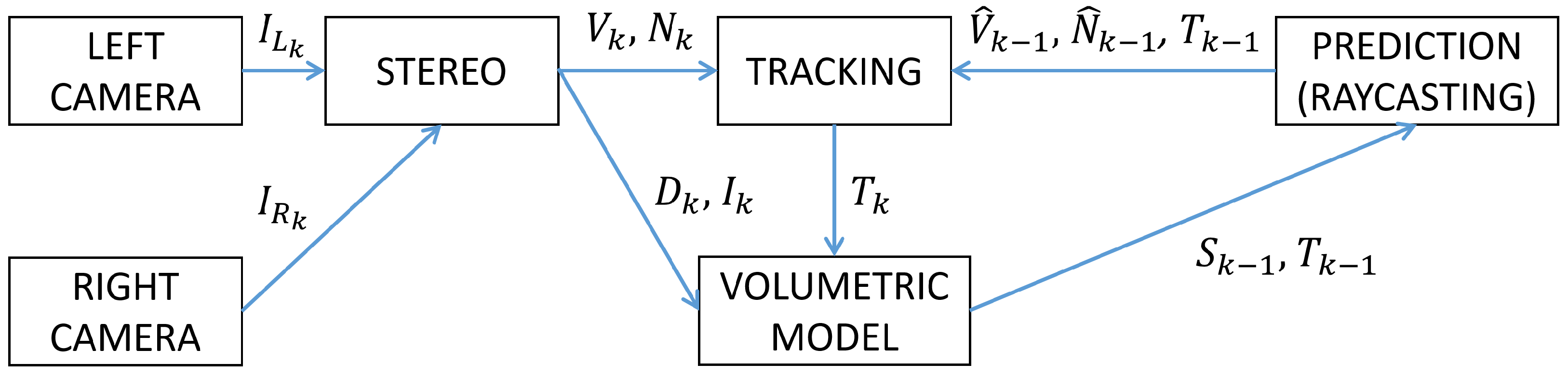
Abstract
1. Introduction
2. Background
3. Algorithm
3.1. Stereo
3.2. Volumetric Model Representation
3.3. Camera Pose Estimation
3.3.1. Depth Tracking
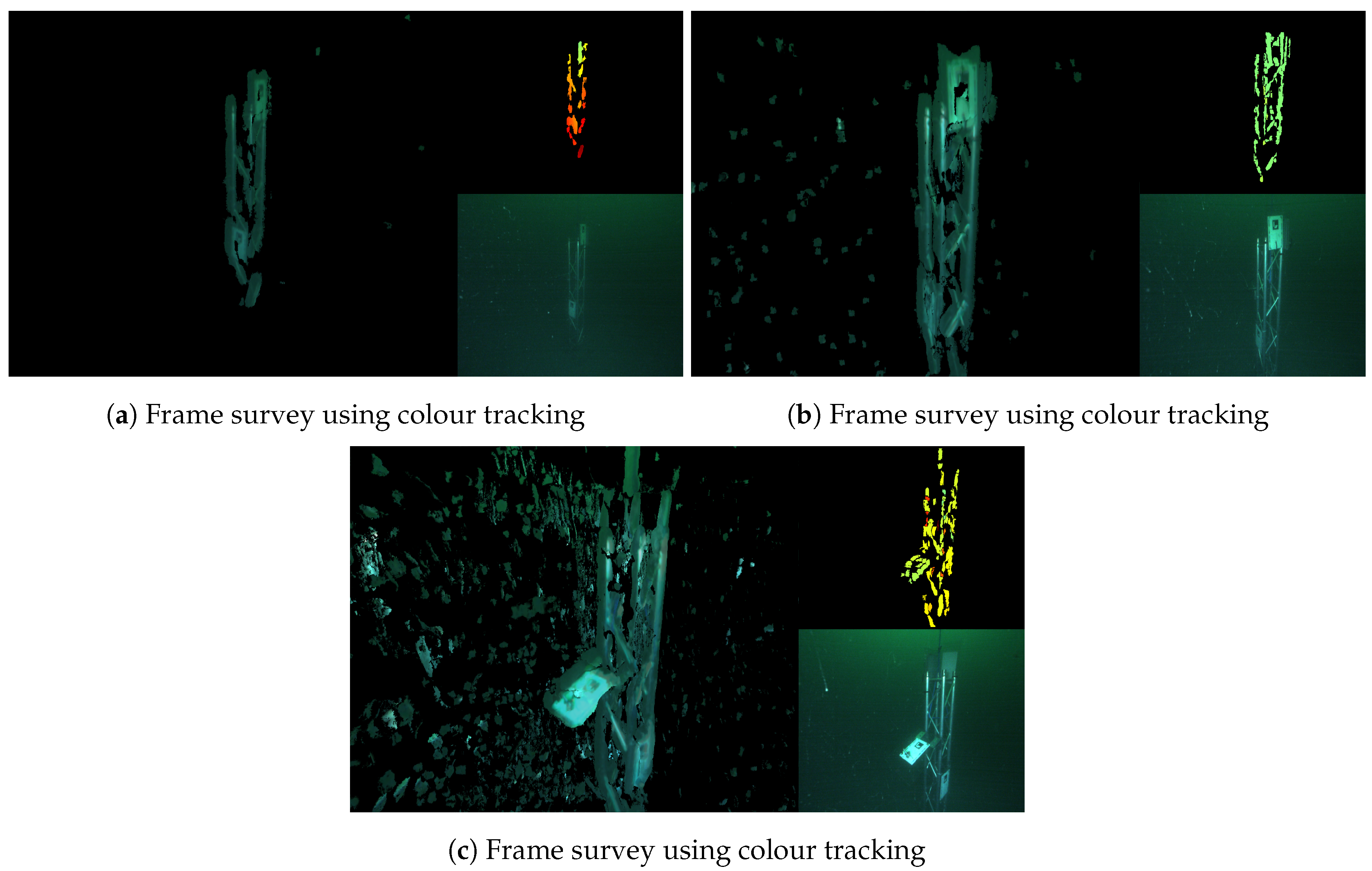
3.3.2. Colour Tracking
3.4. Raycasting
4. Implementation
4.1. Software
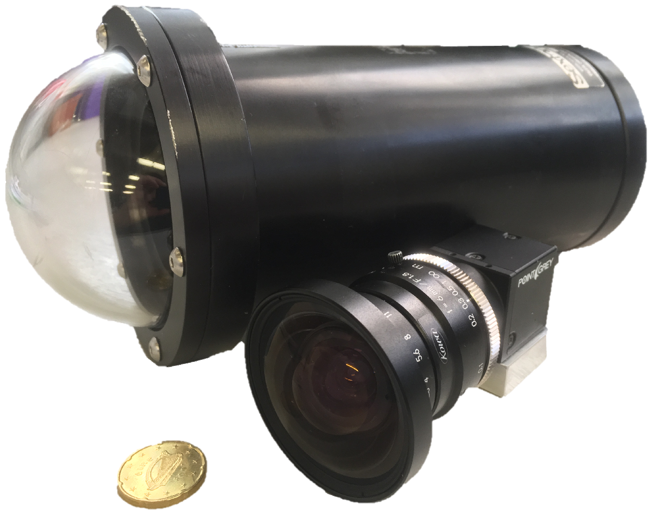
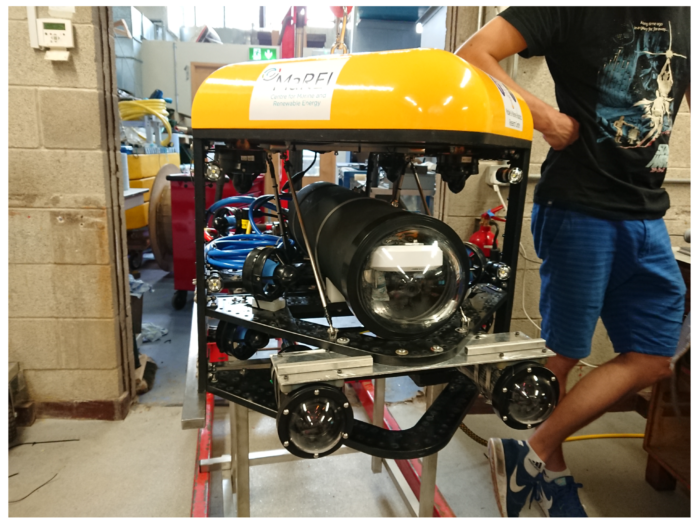
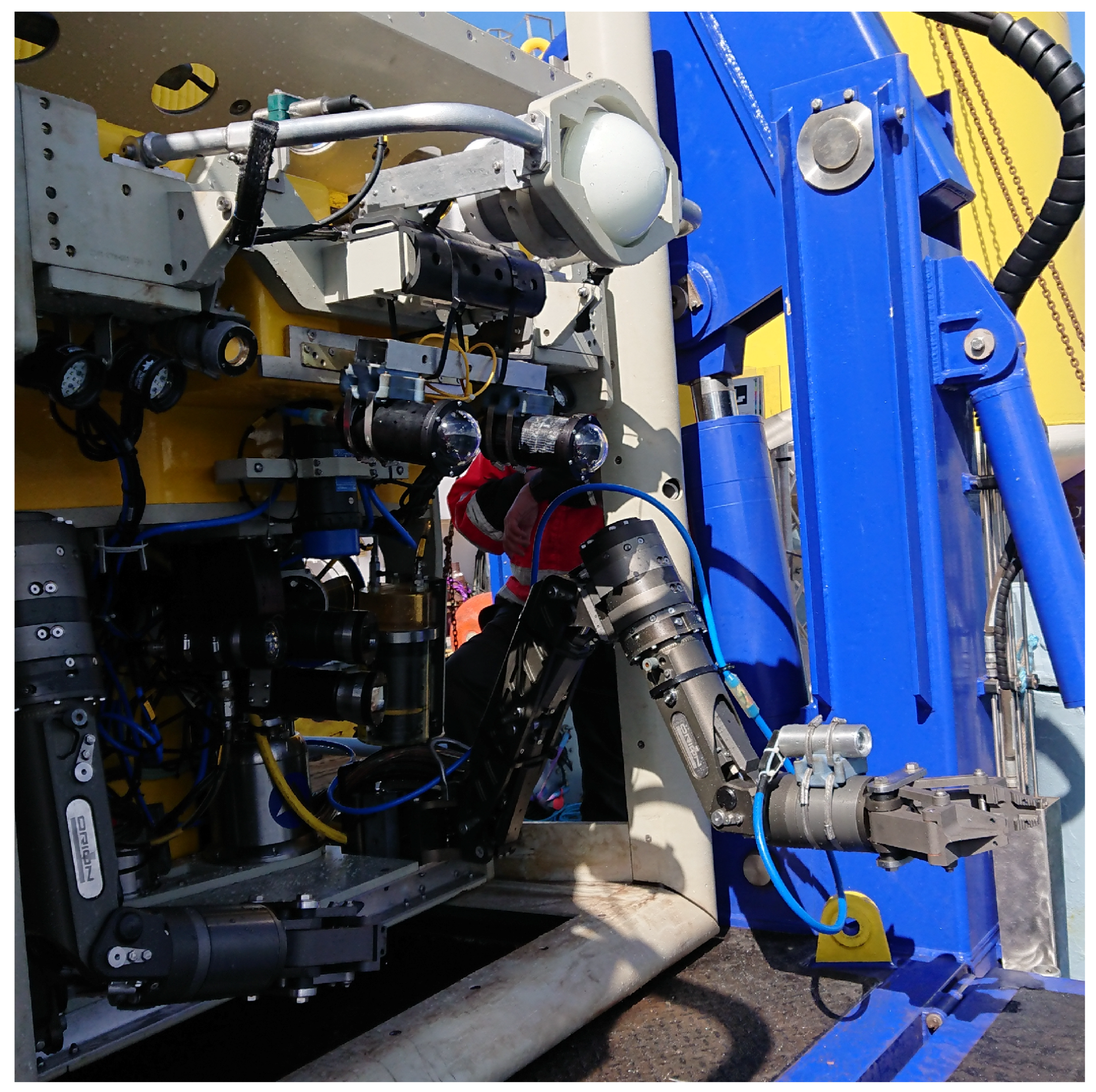
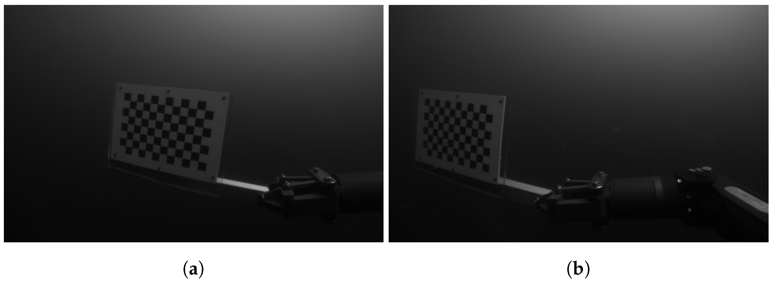
4.2. Stereo Rig
5. Results
5.1. Good Visibility, Fresh Water
5.2. Bad Visibility, Sea Water
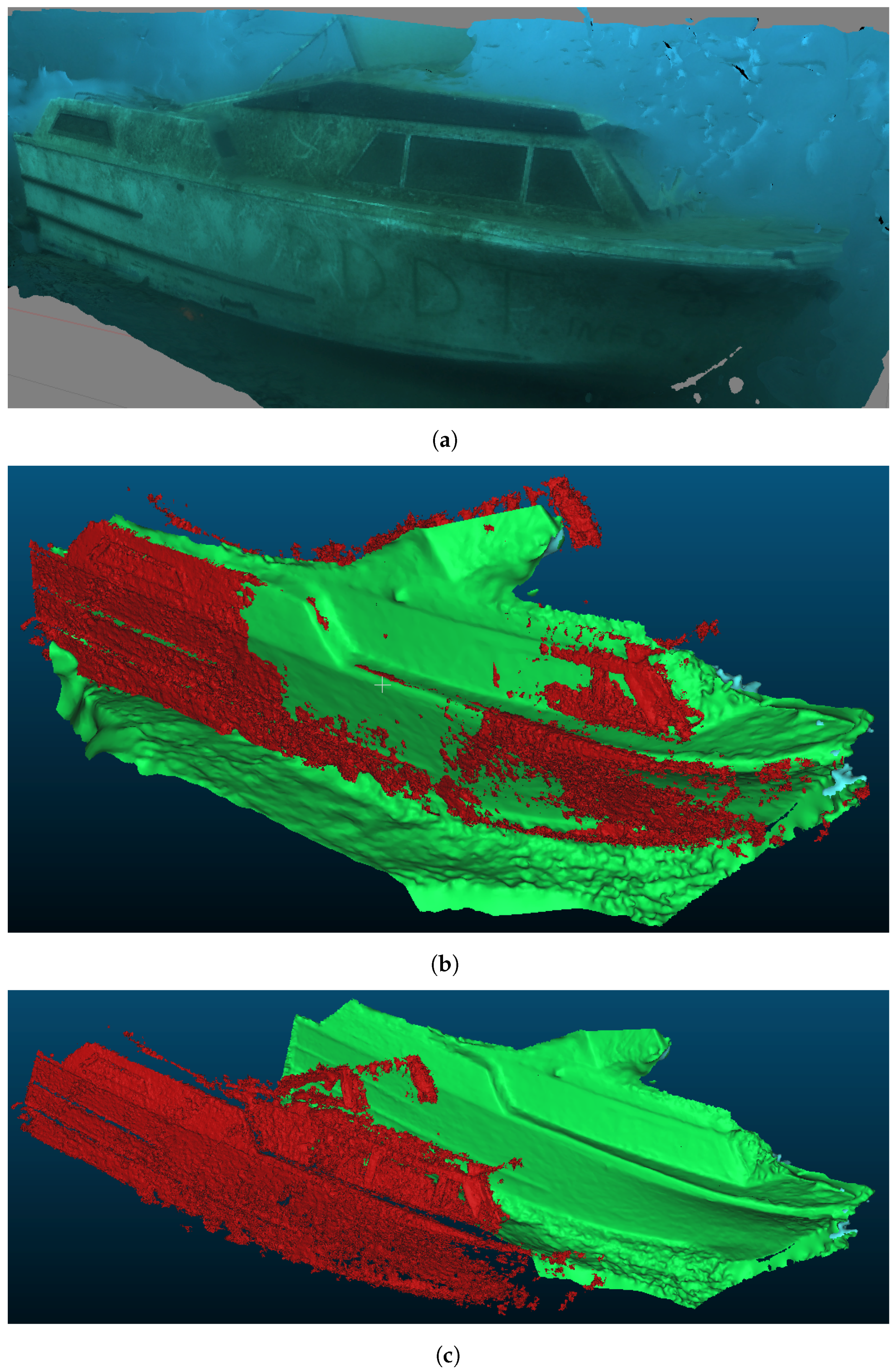
5.3. Qualitative Comparison to Post-Processed Photogrammetry
6. Conclusions and Future Work
Author Contributions
Funding
Conflicts of Interest
Abbreviations
| ROV | Remotely operated vehicle |
| AUV | Autonomous underwater vehicle |
| SLAM | Simultaneous localisation and mapping |
| GPU | Graphics processing unit |
| GPGPU | General purpose GPU |
| ICP | Iterative closest point |
| SDF | Signed distance function |
| TSDF | Truncated SDF |
| FOV | Field of view |
| RGB | Red, green, blue |
| RGBD | RGB + depth |
| CMOS | Complementary Metal-Oxide-Semiconductor |
References
- Chapman, P.; Bale, K.; Drap, P. We All Live in a Virtual Submarine. IEEE Comput. Graph. Appl. 2010, 30, 85–89. [Google Scholar] [CrossRef] [PubMed]
- Cocito, S.; Sgorbini, S.; Peirano, A.; Valle, M. 3-D reconstruction of biological objects using underwater video technique and image processing. J. Exp. Mar. Biol. Ecol. 2003, 297, 57–70. [Google Scholar] [CrossRef]
- Negahdaripour, S.; Firoozfam, P. An ROV Stereovision System for Ship-Hull Inspection. IEEE J. Ocean. Eng. 2006, 31, 551–564. [Google Scholar] [CrossRef]
- Ledezma, F.D.; Amer, A.; Abdellatif, F.; Outa, A.; Trigui, H.; Patel, S.; Binyahib, R. A Market Survey of Offshore Underwater Robotic Inspection Technologies for the Oil and Gas Industry. Soc. Pet. Eng. 2015. [Google Scholar] [CrossRef]
- Antonelli, G. Underwater Robots; Springer Tracts in Advanced Robotics; Springer: Berlin, Germany, 2014; Volume 96. [Google Scholar]
- Elvander, J.; Hawkes, G. ROVs and AUVs in support of marine renewable technologies. In Proceedings of the 2012 Oceans, Hampton Roads, VA, USA, 14–19 October 2012; pp. 1–6. [Google Scholar] [CrossRef]
- Allotta, B.; Conti, R.; Costanzi, R.; Fanelli, F.; Gelli, J.; Meli, E.; Monni, N.; Ridolfi, A.; Rindi, A. A Low Cost Autonomous Underwater Vehicle for Patrolling and Monitoring. Proc. Inst. Mech. Eng. Part M J. Eng. Marit. Environ. 2017, 231, 740–749. [Google Scholar] [CrossRef]
- Ferreira, F.; Veruggio, G.; Caccia, M.; Bruzzone, G. A Survey on Real-Time Motion Estimation Techniques for Underwater Robots. J. Real-Time Image Process. 2016, 11, 693–711. [Google Scholar] [CrossRef]
- Sivčev, S.; Rossi, M.; Coleman, J.; Dooly, G.; Omerdić, E.; Toal, D. Fully Automatic Visual Servoing Control for Work-Class Marine Intervention ROVs. Control Eng. Pract. 2018, 74, 153–167. [Google Scholar] [CrossRef]
- Sivčev, S.; Coleman, J.; Adley, D.; Dooly, G.; Omerdić, E.; Toal, D. Closing the Gap between Industrial Robots and Underwater Manipulators. In Proceedings of the OCEANS 2015-MTS/IEEE Washington, Washington, DC, USA, 19–22 October 2015; pp. 1–7. [Google Scholar] [CrossRef]
- Cieslak, P.; Ridao, P.; Giergiel, M. Autonomous underwater panel operation by GIRONA500 UVMS: A practical approach to autonomous underwater manipulation. In Proceedings of the 2015 IEEE International Conference on Robotics and Automation (ICRA), Seattle, WA, USA, 26–30 May 2015; pp. 529–536. [Google Scholar] [CrossRef]
- Ribas, D.; Ridao, P.; Turetta, A.; Melchiorri, C.; Palli, G.; Fernandez, J.; Sanz, P. I-AUV Mechatronics Integration for the TRIDENT FP7 Project. IEEE/ASME Trans. Mechatron. 2015. [Google Scholar] [CrossRef]
- Omerdic, E.; Toal, D. OceanRINGS: System concept & applications. In Proceedings of the 2012 20th Mediterranean Conference on Control Automation (MED), Barcelona, Spain, 3–6 July 2012; pp. 1391–1396. [Google Scholar] [CrossRef]
- Rossi, M.; Scaradozzi, D.; Drap, P.; Recanatini, P.; Dooly, G.; Omerdić, E.; Toal, D. Real-Time Reconstruction of Underwater Environments: From 2D to 3D. In Proceedings of the OCEANS 2015-MTS/IEEE Washington, Washington, DC, USA, 19–22 October 2015; pp. 1–6. [Google Scholar] [CrossRef]
- Newcombe, R.A.; Izadi, S.; Hilliges, O.; Molyneaux, D.; Kim, D.; Davison, A.J.; Kohi, P.; Shotton, J.; Hodges, S.; Fitzgibbon, A. KinectFusion: Real-Time Dense Surface Mapping and Tracking. In Proceedings of the 2011 10th IEEE International Symposium on Mixed and Augmented Reality (ISMAR), Basel, Switzerland, 26–29 October 2011; pp. 127–136. [Google Scholar] [CrossRef]
- Izadi, S.; Kim, D.; Hilliges, O.; Molyneaux, D.; Newcombe, R.; Kohli, P.; Shotton, J.; Hodges, S.; Freeman, D.; Davison, A.; et al. KinectFusion: Real-Time 3D Reconstruction and Interaction Using a Moving Depth Camera. In Proceedings of the 24th Annual ACM Symposium on User Interface Software and Technology (UIST ’11), Santa Barbara, CA, USA, 16–19 October 2011; ACM: New York, NY, USA, 2011; pp. 559–568. [Google Scholar] [CrossRef]
- Hartley, R.; Zisserman, A. Multiple View Geometry in Computer Vision, 2nd ed.; Cambridge University Press: New York, NY, USA, 2003. [Google Scholar]
- Thrun, S. Robotic Mapping: A Survey. In Exploring Artificial Intelligence in the New Millenium; Morgan Kaufmann: Burlington, MA, USA, 2002. [Google Scholar]
- Davison, A.J. Real-Time Simultaneous Localisation and Mapping with a Single Camera. In Proceedings of the Ninth IEEE International Conference on Computer Vision (ICCV ’03), Nice, France, 13–16 October 2003; IEEE Computer Society: Washington, DC, USA, 2003; Volume 2, p. 1403. [Google Scholar]
- Nister, D.; Naroditsky, O.; Bergen, J. Visual Odometry. In Proceedings of the 2004 IEEE Computer Society Conference on Computer Vision and Pattern Recognition (CVPR 2004), Washington, DC, USA, 27 June–2 July 2004; Volume 1. [Google Scholar]
- Chaves, S.M.; Galceran, E.; Ozog, P.; Walls, J.M.; Eustice, R.M. Pose-Graph SLAM for Underwater Navigation. In Sensing and Control for Autonomous Vehicles: Applications to Land, Water and Air Vehicles; Fossen, T.I., Pettersen, K.Y., Nijmeijer, H., Eds.; Lecture Notes in Control and Information Sciences; Springer International Publishing: Cham, Switzerland, 2017; pp. 143–160. [Google Scholar]
- Bonin-Font, F.; Cosic, A.; Negre, P.L.; Solbach, M.; Oliver, G. Stereo SLAM for Robust Dense 3D Reconstruction of Underwater Environments. In Proceedings of the OCEANS 2015-Genova, Genoa, Italy, 18–21 May 2015; pp. 1–6. [Google Scholar] [CrossRef]
- Klein, G.; Murray, D. Parallel Tracking and Mapping for Small AR Workspaces. In Proceedings of the 2007 6th IEEE and ACM International Symposium on Mixed and Augmented Reality (ISMAR ’07), Nara, Japan, 13–16 November 2007; IEEE Computer Society: Washington, DC, USA, 2007; pp. 1–10. [Google Scholar] [CrossRef]
- Chambolle, A.; Pock, T. A First-Order Primal-Dual Algorithm for Convex Problems with Applications to Imaging. J. Math. Imag. Vis. 2010, 40, 120–145. [Google Scholar] [CrossRef]
- Newcombe, R.A.; Davison, A.J. Live Dense Reconstruction with a Single Moving Camera. In Proceedings of the 2010 IEEE Conference on Computer Vision and Pattern Recognition (CVPR), San Francisco, CA, USA, 13–18 June 2010; pp. 1498–1505. [Google Scholar] [CrossRef]
- Graber, G.; Pock, T.; Bischof, H. Online 3D Reconstruction Using Convex Optimization. In Proceedings of the 2011 IEEE International Conference on Computer Vision Workshops (ICCV Workshops), Barcelona, Spain, 6–13 November 2011; pp. 708–711. [Google Scholar] [CrossRef]
- Newcombe, R.A.; Lovegrove, S.; Davison, A. DTAM: Dense Tracking and Mapping in Real-Time. In Proceedings of the 2011 IEEE International Conference on Computer Vision (ICCV), Barcelona, Spain, 6–13 November 2011; pp. 2320–2327. [Google Scholar] [CrossRef]
- Anwer, A.; Ali, S.S.A.; Khan, A.; Mériaudeau, F. Underwater 3-D Scene Reconstruction Using Kinect v2 Based on Physical Models for Refraction and Time of Flight Correction. IEEE Access 2017, 5, 15960–15970. [Google Scholar] [CrossRef]
- Lu, H.; Zhang, Y.; Li, Y.; Zhou, Q.; Tadoh, R.; Uemura, T.; Kim, H.; Serikawa, S. Depth Map Reconstruction for Underwater Kinect Camera Using Inpainting and Local Image Mode Filtering. IEEE Access 2017, 5, 7115–7122. [Google Scholar] [CrossRef]
- Yilmaz, O.; Karakus, F. Stereo and Kinect Fusion for Continuous 3D Reconstruction and Visual Odometry. In Proceedings of the 2013 International Conference on Electronics, Computer and Computation (ICECCO), Ankara, Turkey, 7–9 November 2013; pp. 115–118. [Google Scholar] [CrossRef]
- Hogue, A.; German, A.; Jenkin, M. Underwater Environment Reconstruction Using Stereo and Inertial Data. In Proceedings of the 2007 IEEE International Conference on Systems, Man and Cybernetics, Montreal, QC, Canada, 7–10 October 2007; pp. 2372–2377. [Google Scholar] [CrossRef]
- Servos, J.; Smart, M.; Waslander, S.L. Underwater Stereo SLAM with Refraction Correction. In Proceedings of the 2013 IEEE/RSJ International Conference on Intelligent Robots and Systems, Tokyo, Japan, 3–7 November 2013; pp. 3350–3355. [Google Scholar] [CrossRef]
- Wu, Y.; Nian, R.; He, B. 3D Reconstruction Model of Underwater Environment in Stereo Vision System. In Proceedings of the 2013 OCEANS-San Diego, San Diego, CA, USA, 23–27 September 2013; pp. 1–4. [Google Scholar] [CrossRef]
- Hurtós, N.; Nagappa, S.; Palomeras, N.; Salvi, J. Real-Time Mosaicing with Two-Dimensional Forward-Looking Sonar. In Proceedings of the 2014 IEEE International Conference on Robotics and Automation (ICRA), Hong Kong, China, 31 May–7 June 2014; pp. 601–606. [Google Scholar] [CrossRef]
- Li, H.; Dong, Y.; He, X.; Xie, S.; Luo, J. A Sonar Image Mosaicing Algorithm Based on Improved SIFT for USV. In Proceedings of the 2014 IEEE International Conference on Mechatronics and Automation, Tianjin, China, 3–6 August 2014; pp. 1839–1843. [Google Scholar] [CrossRef]
- Lagudi, A.; Bianco, G.; Muzzupappa, M.; Bruno, F. An Alignment Method for the Integration of Underwater 3D Data Captured by a Stereovision System and an Acoustic Camera. Sensors 2016, 16, 536. [Google Scholar] [CrossRef] [PubMed]
- Digumarti, S.T.; Chaurasia, G.; Taneja, A.; Siegwart, R.; Thomas, A.; Beardsley, P. Underwater 3D Capture Using a Low-Cost Commercial Depth Camera. In Proceedings of the 2016 IEEE Winter Conference on Applications of Computer Vision (WACV), Lake Placid, NY, USA, 7–10 March 2016; pp. 1–9. [Google Scholar] [CrossRef]
- Dancu, A.; Fourgeaud, M.; Franjcic, Z.; Avetisyan, R. Underwater Reconstruction Using Depth Sensors. In Proceedings of the SIGGRAPH Asia 2014 Technical Briefs (SA ’14), Shenzhen, China, 3–6 December 2014. [Google Scholar]
- Fusiello, A.; Trucco, E.; Verri, A. A Compact Algorithm for Rectification of Stereo Pairs. Mach. Vis. Appl. 2000, 12, 16–22. [Google Scholar] [CrossRef]
- Brown, M.Z.; Burschka, D.; Hager, G.D. Advances in Computational Stereo. IEEE Trans. Pattern Anal. Mach. Intell. 2003, 25, 993–1008. [Google Scholar] [CrossRef]
- Curless, B.; Levoy, M. A Volumetric Method for Building Complex Models from Range Images. In Proceedings of the 23rd Annual Conference on Computer Graphics and Interactive Techniques, New Orleans, LA, USA, 4–9 August 1996; pp. 303–312. [Google Scholar]
- Rusinkiewicz, S.; Levoy, M. Efficient Variants of the ICP Algorithm. In Proceedings of the Third International Conference on 3-D Digital Imaging and Modeling, Quebec City, QC, Canada, 28 May–1 June 2001; pp. 145–152. [Google Scholar] [CrossRef]
- Chen, Y.; Medioni, G. Object Modeling by Registration of Multiple Range Images. In Proceedings of the 1991 IEEE International Conference on Robotics and Automation, Sacramento, CA, USA, 9–11 April 1991; Volume 3, pp. 2724–2729. [Google Scholar] [CrossRef]
- Low, K.L. Linear Least-Squares Optimization for Point-to-Plane ICP Surface Registration; Technical Report; University of North Carolina at Chapel Hill: Chapel Hill, NC, USA, 2004. [Google Scholar]
- Prisacariu, V.A.; Kähler, O.; Cheng, M.M.; Ren, C.Y.; Valentin, J.; Torr, P.H.S.; Reid, I.D.; Murray, D.W. A Framework for the Volumetric Integration of Depth Images. arXiv 2014, arXiv:cs/1410.0925. [Google Scholar]
- Marquardt, D. An Algorithm for Least-Squares Estimation of Nonlinear Parameters. J. Soc. Ind. Appl. Math. 1963, 11, 431–441. [Google Scholar] [CrossRef]
- Parker, S.; Shirley, P.; Livnat, Y.; Hansen, C.; Sloan, P. Interactive Ray Tracing for Isosurface Rendering. In Proceedings of the Visualization ’98, Research Triangle Park, NC, USA, 18–23 October 1998; pp. 233–238. [Google Scholar] [CrossRef]
- Kähler, O.; Prisacariu, V.A.; Ren, C.Y.; Sun, X.; Torr, P.; Murray, D. Very High Frame Rate Volumetric Integration of Depth Images on Mobile Devices. IEEE Trans. Vis. Comput. Graph. 2015, 21, 1241–1250. [Google Scholar] [CrossRef] [PubMed]
- Ravi. Fork of the Voxel Hashing Based Volumetric Integration of Depth Images, InfiniTAM, That Enables ROS as an Input Source. 2017. Available online: https://github.com/ravich2-7183/InfiniTAM (accessed on 7 October 2018).
- Technical Application Notes. Available online: https://www.ptgrey.com/tan/11052 (accessed on 22 May 2018).
- Brown, D.C. Decentering Distortion of Lenses. Photogramm. Eng. Remote Sens. 1966, 32, 444–462. [Google Scholar]
- Agisoft PhotoScan. Available online: http://www.agisoft.com/ (accessed on 26 October 2018).
- Pradeep, V.; Rhemann, C.; Izadi, S.; Zach, C.; Bleyer, M.; Bathiche, S. MonoFusion: Real-Time 3D Reconstruction of Small Scenes with a Single Web Camera. In Proceedings of the 2013 IEEE International Symposium on Mixed and Augmented Reality (ISMAR), Adelaide, Australia, 1–4 October 2013; pp. 83–88. [Google Scholar] [CrossRef]


© 2018 by the authors. Licensee MDPI, Basel, Switzerland. This article is an open access article distributed under the terms and conditions of the Creative Commons Attribution (CC BY) license (http://creativecommons.org/licenses/by/4.0/).
Share and Cite
Rossi, M.; Trslić, P.; Sivčev, S.; Riordan, J.; Toal, D.; Dooly, G. Real-Time Underwater StereoFusion. Sensors 2018, 18, 3936. https://doi.org/10.3390/s18113936
Rossi M, Trslić P, Sivčev S, Riordan J, Toal D, Dooly G. Real-Time Underwater StereoFusion. Sensors. 2018; 18(11):3936. https://doi.org/10.3390/s18113936
Chicago/Turabian StyleRossi, Matija, Petar Trslić, Satja Sivčev, James Riordan, Daniel Toal, and Gerard Dooly. 2018. "Real-Time Underwater StereoFusion" Sensors 18, no. 11: 3936. https://doi.org/10.3390/s18113936
APA StyleRossi, M., Trslić, P., Sivčev, S., Riordan, J., Toal, D., & Dooly, G. (2018). Real-Time Underwater StereoFusion. Sensors, 18(11), 3936. https://doi.org/10.3390/s18113936