1. Introduction
The detection of human body parts has been popularly researched in the computer vision and pattern recognition fields. Accurate detection of body parts is important in human pose estimation for activity recognition, which is utilized by various smart systems including: Human computer interaction (HCI), surveillance, healthcare, and entertainment. Recently, it has converged with the virtual reality (VR) and augmented reality (AR) techniques in the training field [
1].
Early approaches using a single camera tried to detect the region of interest by extracting the features from illumination, color, and edge information on 2D images. In these approaches, machine learning algorithms such as adaptive boosting (AdaBoost), support vector machine (SVM), and gaussian mixture model (GMM) are used to extract key body features such as face, torso, hands, and feet from a large data set. However, a reliable detection of such features is difficult to achieve due to the background noises and illumination changes on the images. The recent availability of red, green, blue, and depth (RGB-D) cameras, such as Microsoft Kinect [
2] and Intel RealSense [
3] provides depth data and suggests a more reliable way to detect the features. Using depth information retrieved from an infrared sensor, the region of interest on the human body can be segmented more precisely without background ambiguities.
The joints of the human body can provide useful information for motion analysis. Using a single RGB-D camera, the approach introduced by Shotton et al. [
4] has been widely used to detect human body parts as a hierarchical skeleton structure. In their approach, a list of joint positions is estimated from a user who faces the RGB-D camera by using the random statistical model. However, its accuracy, especially for internal joints, is sensitive to the input pose. For example, the joint positions of occluded body parts might be either skipped or incorrectly estimated from unknown poses. Using multiple cameras around the user, a set of depth images captured from different viewpoints can be combined to complement the occluded body parts [
5,
6,
7,
8,
9,
10,
11]. In these approaches, an optimization problem should be solved to track a list of joints in an articulated model from the depth volume.
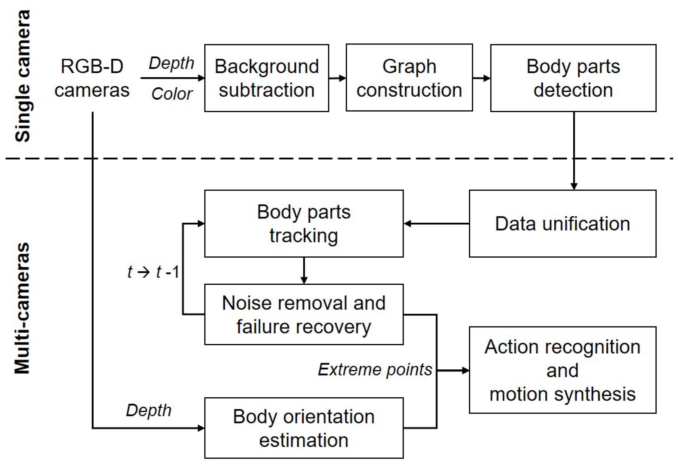
In this paper, we introduce a marker-less system for human pose estimation by detecting and tracking key body parts, namely, the head, hands, and feet. Given color and depth images captured by multiple RGB-D (two Kinect) cameras, our system detects a set of extreme points on the key body parts from each camera (i.e., the single camera process) and tracks them from the unified data received from the multiple cameras (i.e., the multi-camera process) as shown in
Figure 1. During the single camera process, a quadtree-based graph model with segmented regions is constructed from the color and depth images received from a single camera. Using geodesic distances on the graph, a set of candidate points is searched and selected as extreme points through a supervised learning model. During the multi-camera process, the optimal extreme points are selected and tracked from the unified data received from the multiple cameras. For a better tracking performance, a Kalman filter-based method is introduced to reduce positional noises and to recover from a failure of tracking extremes.
Unlike the previous approaches, our system does not reconstruct a full skeleton structure from input data. Instead, input poses are abstracted with a small set of extreme points on the key body parts, making the detecting and tracking processes easier without solving the optimization problem for skeleton reconstruction. Using a small set of extremes as input data, our system can be applied to recognize a human action or to synthesize a motion sequence from a few key poses in real time. As demonstrated in the experimental results, our system shows an average of 87% accuracy against the commercial system, which outperforms the multi-Kinects system with more RGB-D cameras used.
The rest of this paper is organized as follows. Previous approaches for human pose estimation are reviewed in
Section 2. The detection of key body parts from each camera is described in
Section 3, while tracking them from the unified data received from multiple cameras is detailed in
Section 4. The experimental results for tracking accuracy, action recognition, and motion synthesis are demonstrated in
Section 5. We conclude this paper with a discussion of potential improvements in
Section 6.
2. Related Work
Detecting and tracking human body parts from sensor data has been actively researched in computer vision and recognition fields. Using single or multiple RGB-D cameras, the majority of the detection approaches can be differentiated into three categories: Generative (aka top-down), discriminative (aka bottom-up), and hybrid.
The generative approaches [
12,
13,
14] rely on a template model of the human body and try to estimate the model parameters that best describe the pose in an input image. Using the iterative closest point (ICP) algorithm, Grest et al. [
12] defined a nonlinear optimization function and estimated a human pose by applying the analytically simplified Jacobian. Based on the probabilistic inferencing algorithm, Zhu et al. [
13] performed feature detection on depth images and estimated relatively simple poses from the detected features. Ganapathi et al. [
14] performed real-time detection from a sequence of depth images based on the probabilistic temporal model. In their approach, a set of physical and free space constraints are derived to deform the template model. Shuai et al. [
15] used multiple depth cameras to minimize occlusion and designed an ellipsoid-based skeleton model to capture the geometry detail of a tracked object. In these ICP-based approaches, the external template model and its parameters need to be configured in advance to initiate the tracking process, which is computationally expensive for a complicated model such as a human body. On the other hand, our system uses no template model and its parameters to track human poses.
The discriminative approaches [
4,
16,
17,
18,
19] try to detect the body parts directly from the observed data without using an initialization process with a template model. Shotton et al. [
4] estimated a list of 3D joint positions on a single depth image by performing per-pixel classification which uses a randomized decision tree with a large image set. Their approach was further exploited by Girshick et al. [
16], in which they anticipated the occluded joint positions using the regression forest with relative 3D offset information. Shen et al. [
17] introduced an example-based approach which corrects occluded body parts, such as a side view. In their approach, a regression forest is learned based on the differences between the motion capture and Kinect data. Recently, Jung et al. [
18] improved the performance of joint estimation using a random tree walk, while Shafaei and Little [
19] improved the joint estimation accuracy by applying a convolutional neural network (CNN) based pixel classification. Using the discriminative approaches, the joint positions can be estimated in real time given a large set of high quality data for the training process. For example, Shotton et al. [
4] trained each tree with 300,000 images while Shafaei and Little [
19] collected a six million data set for their classification. However, our approach searches for a set of key body parts from the hierarchical graph structure using a much smaller set of samples (i.e., less than 1000).
Given a database of human motion, the hybrid approaches [
20,
21,
22,
23] try to improve the tracking accuracy by combining the generative and discriminative methods (i.e., solving the optimization problems with the database reference). Ganapathi et al. [
20] demonstrated an interactive system that estimates body parts in a kinematic chain structure using the hill-climbing method. In their method, a local detector for body parts (i.e., a discriminative model) is used to initiate a tracking failure. Ye et al. [
21] stored a set of a 3D skeleton and its mesh data into a database and obtained the optimal pose by matching the point cloud data through the shape refinement process. Baak et al. [
22] showed a method of comparing the joint positions at previous frames and the salient body parts extracted from the depth information to search for similar poses. Later, Helten et al. [
23] presented a similar approach with a personalized body tracker that improves the lookup accuracy from the regenerated database. Like the discriminative approaches, an extensive set of samples needs to be prepared in advanced for most hybrid approaches to estimate accurate human poses. For example, Ye et al. [
21] captured 19,000 samples from a motion capture system, and Baak et al. [
22] selected about 25,000 samples. Furthermore, these approaches are sensitive to the physical property of a user such as a body size and require an additional fitting process to track poses from unknown users, making the approaches less applicable to general users. Using multiple cameras, our approach does not require prior body information to track poses from unknown users; hence, it is more applicable to real-time human action recognition and motion synthesis for unspecified individuals.
Recently, multiple depth cameras [
5,
6,
7,
8,
9,
10,
11] have been adopted to overcome the joint occlusion problems by using the unified data captured at different view points. Zhang et al. [
5] used multiple Kinects for non-skeletal motion data while Kaenchan et al. [
6] applied them for a walking analysis. Kitsikidis et al. [
7] adopted a hidden conditional random fields (HCRF) classifier to detect patterns in dance motion. With two synchronized cameras, Michel et al. [
8] solved an optimization problem using stochastic optimization techniques to track a human body from the depth volume. Moon et al. [
9] adopted a Kalman filter framework to combine the multiple depth data to improve the occlusion problem. Recently, Kim et al. [
10,
11] demonstrated a large scale of multi-Kinects system to capture dynamic motion in dance and martial arts. Most of the time, these approaches rely on the Kinect method [
4] to configure the skeleton structure in an articulated model, which often requires an expensive and complicated post process to enhance naturalness in an output pose. On the other hand, our system detects a small set of key body parts and uses them as inputs to refer to the existing motion data for estimating a dynamic human pose.
3. Single Camera Process
Our system acquires a continuous sequence of RGB-D images from multiple cameras. For each camera, major body parts are detected through three steps: Background subtraction, quadtree-based graph construction, and part joint detection using accumulative geodesic distances and a local detector. The details of the steps are described in the subsequence sections.
3.1. Background Subtraction
In our system, the RGB-D cameras provide a continuous sequence of color and depth images with same resolution, and both images are calibrated. Given a sequence of color and depth images streamed from a single RGB-D camera, the background information is subtracted from the images to isolate a human object based on the depth information as it is robust to the illumination changes. We captured the first frame of the depth sequence, where no human is visible and subtracted it from subsequent frames. For the depth images with a human object, a threshold value (i.e., the minimum depth value for each pixel) is used to distinguish between the background and foreground objects. This simple method is sensitive to background noises and can generate false positives, especially at the edges of the human object [
24]. As a post-processing step, a morphological erode operation and Sobel kernels are applied to reduce such false positive areas. We compute approximation of vertical and horizontal derivatives using Sobel kernels and remove noises from depth images based on gradient magnitudes. From a filtered depth image,
, a corresponding color image,
, can be obtained. We refer a filtered image,
. This simple technique works well for a low-resolution depth image. However, a more sophisticated method for the background subtraction could be used using a hardware acceleration [
25].
3.2. Graph Construction
Inspired by the work identifying geodesic extreme positions using a graph structure [
26,
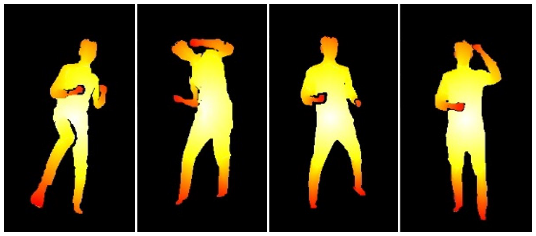
27], our detection method assumes the nature of an invariant body structure such that the accumulative geodesic distances between the center of body and key body parts such as head (H), right hand (RH), left hand (LH), right foot (RF), and left foot (LF) do not change regardless of the human poses as shown in
Figure 2. For example, let
be a center position of the human object averaged from
and the positions of extreme points,
, on the key body parts are located farthest from
, where
and
. Based on this geodesic characteristic, both
and
can be represented as a graph model,
G. As shown in Algorithm 1, a quadtree-based segmentation is used to group neighboring data efficiently, and each node has a representative value with the center position.
| Algorithm 1 Graph construction: Here, and are threshold values to split a node into four children. |
- 1:
Input: image , init tree depth - 2:
- 3:
Output: decomposed image with quadtree structure - 4:
- 5:
functionQuadtree() - 6:
- 7:
if () then - 8:
- 9:
return - 10:
- 11:
else - 12:
- 13:
standard deviation of - 14:
- 15:
divider of - 16:
- 17:
standard deviation of - 18:
- 19:
divider of - 20:
- 21:
if () then - 22:
- 23:
= split I as four sub images - 24:
- 25:
return QuadTree() - 26:
- 27:
end if - 28:
- 29:
end if - 30:
- 31:
end function
|
3.3. Body Parts Detection
Algorithm 1 generates an undirected G with a vertex, , which is a leaf node of the quadtree, and a weighted edge which connects to the neighboring vertices of . The weight value can be estimated from the Euclidean distance between the neighboring vertices of .
Let be the number of candidate extreme points and represent the shortest paths from the kth starting vertex, , where , to other nodes in G. Using Dijkstra’s algorithm, a set of the candidate extreme points, , from G can be searched in an iterative way as follows,
When ,
- (1)
Set as a start vertex, , and search G.
- (2)
Save the accumulative geodesic distances of (1) to .
- (3)
Set to the longest accumulative geodesic end point of .
- (4)
Update to .
When ,
- (1)
Set as a start vertex and partially search G such that is nearer to than to .
- (2)
Update to using the result of (1).
- (3)
Set to the longest accumulative geodesic end point of .
- (4)
Update to .
Given
,
for the key body parts can be classified by matching local features. The supervised learning model like SVM requires a relatively small amount of sample data and is well suited for the detection of specific human parts [
28,
29]. For
classification, the image patches of major joints are collected from
, and data augmentation is used to increase the number of the patches. The histograms of gradients for the patches are arranged into a 1D feature vector and used to train the SVM [
30]. During the test process,
is classified within the region of interest for
(i.e., 80 by 80 pixels) by applying a sliding window (i.e., 5 to 20 pixels) with multi-scales for scale-invariant detection.
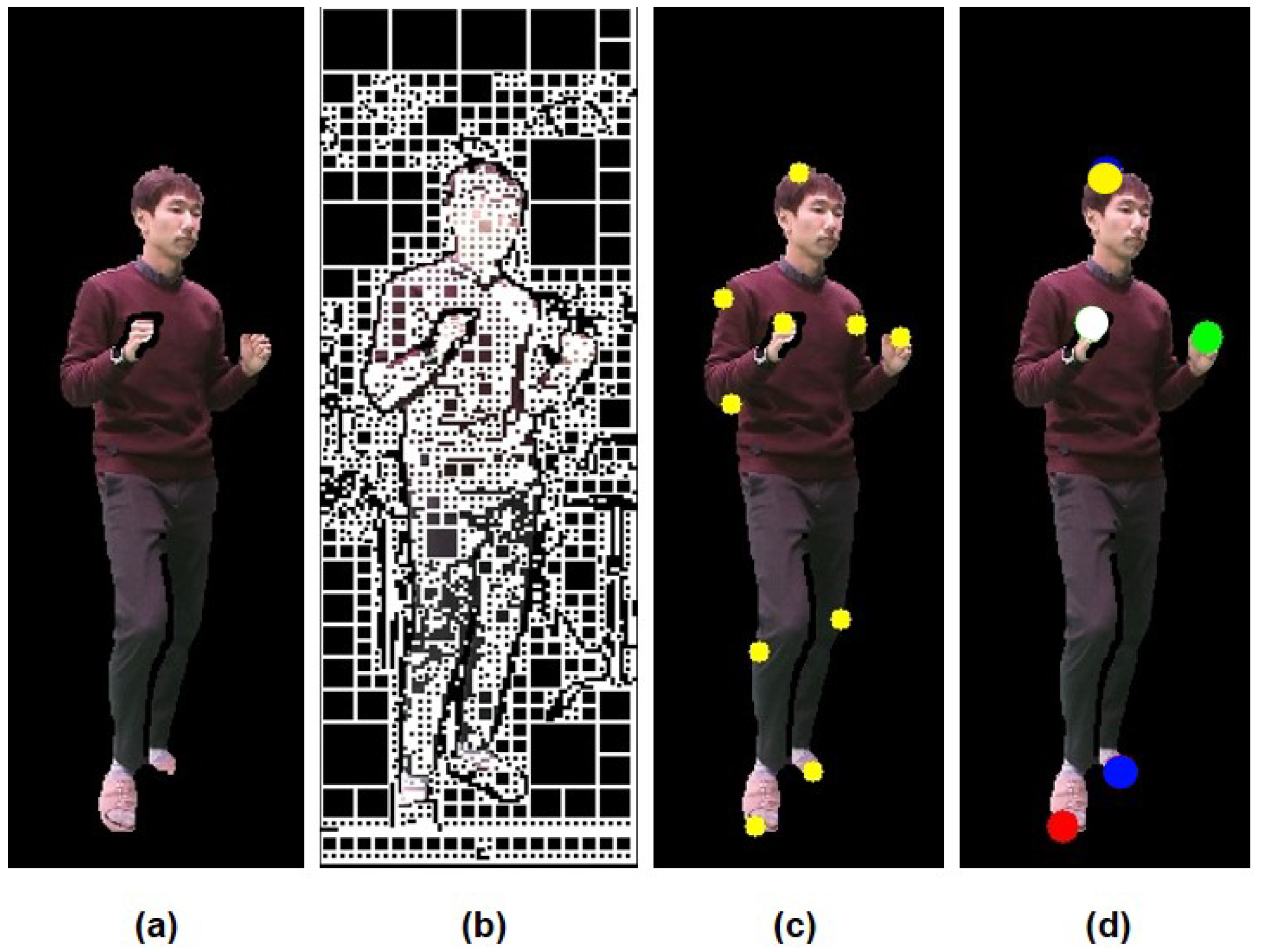
Figure 3 shows the results of each step with
,
,
, and
to specify
.
4. Multi-Camera Process
Our system combines a set of key body parts detected from each camera into a single space and tracks the body parts with minimum errors. This multi-camera process consists of four steps: Data unification in a single coordinate system, body part tracking based on a voting scheme, noise removal and failure recovery with a Kalman-filtered method, and body orientation estimation using principal component analysis (PCA). The details of each step are described in the subsequent sections.
4.1. Data Unification
Using multiple RGB-D cameras, a set of extreme points,
, detected from the
cth camera can be unified into the same coordinate system by using a rigid transformation,
T. If one of the cameras is selected as a reference coordinate system,
T can be estimated from the ICP method [
31] by minimizing the error function,
, where
and
are the rotation and translation of the camera data to the reference system, respectively. This convergence method is capable of an online performance with the input data obtained from multiple cameras; however, the unified result may be erroneous without enough matching points,
, where
and
. As shown in
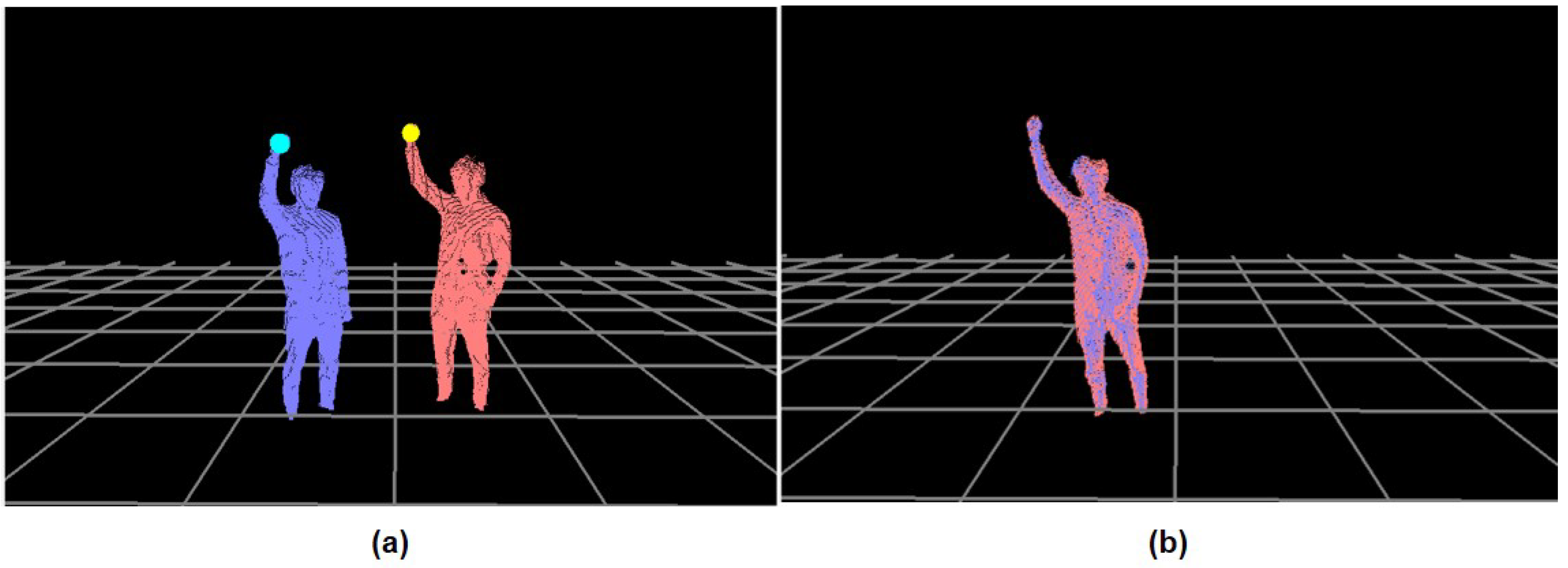
Figure 4,
of the calibration pose is traced from the reference,
, and the
cth camera,
, respectively. Given
,
can be evaluated as follows:
Here,
, where
and
. Given a correlation matrix,
W, between
and
,
Here, the optimal solution for is with derived from a single value decomposition (SVD). Furthermore, is the body rotation between the depth images from the reference camera, , and the cth camera, . This is estimated by a plane defined by the upper three extremes, namely, and and used to enhance the ICP performance. In our system, is collected at every 33 ms until .
4.2. Body Parts Tracking
Given a set of extreme points for each body part in a single coordinate system, our tracking method uses a voting scheme to set a priority for each point. At first, a set of
for each body part
i from the
cth camera forms a candidate group. Within this group, the distance between
below a threshold value (150 mm) is regarded as the same point and counted as a vote,
. Next, the characteristics of human physical constraints are considered using the accumulative geodesic distance for the vote count. For example, starting from
, the end joints such as head, hands, and feet are generally located further than the internal joints such as neck, elbows, and knees. Similarly, the accumulative geodesic distances from
to the end joints are longer than ones to the internal joints. Another vote,
, is counted for the point if the distance from
is larger than another threshold value (a quarter of user’s height). A total vote,
, for
is counted as follows:
Here, and , where , are the vote counts from the distance measure and the range measure, respectively. Furthermore, and are the weight values for and , respectively. In our system, and are set to 2 and 1 to emphasize the importance of the neighboring factor, .
Once
is counted for
,
is tracked based on the minimum Euclidean distance between a tracked point at a previous frame,
, and candidate points at a current frame,
, by maximizing
as follows:
where
is the extreme point from the
cth camera at the
t frame with
votes. Here,
is compared to
in order from the largest
to the smallest one. If the maximum of
is 0, the tracking attempt fails and enters a recovery process described in the following section.
4.3. Noise Removal and Failure Recovery
Whenever the tracking process fails or causes positional noises such as jerky movements in a trajectory of
, our system applies a Kalman filter-based method to correct the erroneous
. Assuming a linear system used for a state-space model in a Kalman filter, the system state model and its measurement model can be defined as follows:
where
t is the time index,
A is the state transition model,
is the state vector,
is the state noise vector,
H is the measurement matrix,
is the measurement vector, and
is the measurement noise vector. Here,
and
are considered to be white noises, which comply to the Gaussian normal distribution with a mean value of 0, a covariance matrix of
, and
. As input arguments to
, the position and velocity of
are used, and
returns a corrected position of
. In our system,
in
Q and
R is set to 0.01 and 1.0, respectively.
Given the state-space model, the Kalman filter estimates a predicted position,
from the prediction and correction steps with
. For example, the prediction step estimates
while the correction step removes the noises in
. During the prediction step, a predicted state vector,
, and a predicted covariance matrix,
, are estimated from a posteriori at
as follows:
where
and
are the posteriori state estimate and the posteriori error covariance matrix at time
, respectively. Here,
replaces
, which failed to be located during the tracking process. During the correction step,
and the Kalman gain matrix,
, are used to update
as follows:
Here,
is the updated state vector, which removes the noises and sets a corrected position of
. Finally, the posteriori error covariance matrix at time
t,
, is estimated as follows:
which will be used during the prediction step at
. To summarize,
from the prediction step and
from the correction step determines
which fails to track or needs to be corrected for its position, respectively. The result of this process for
is shown in
Figure 5.
4.4. Body Orientation Estimation
The body orientation of each pose from
, serve as a useful parameter for motion analysis. In our system, the normal vector at
,
, is estimated using PCA, which finds the best fitting plane from the point locations in
. When PCA is applied to the selected locations in
, the first two eigenvectors define the plane. For example, when a covariance matrix (i.e., a size of 3 by 3) is estimated for the matrix of coordinates from
(i.e., a size of
by 3), where
is the number of points to be fit, it can be decomposed into a set of eigenvectors and eigenvalues. Here, the first two eigenvectors with the largest eigenvalues define a plane; thus, the cross product of these two eigenvectors defines a normal vector (i.e., body orientation),
, on the plane.
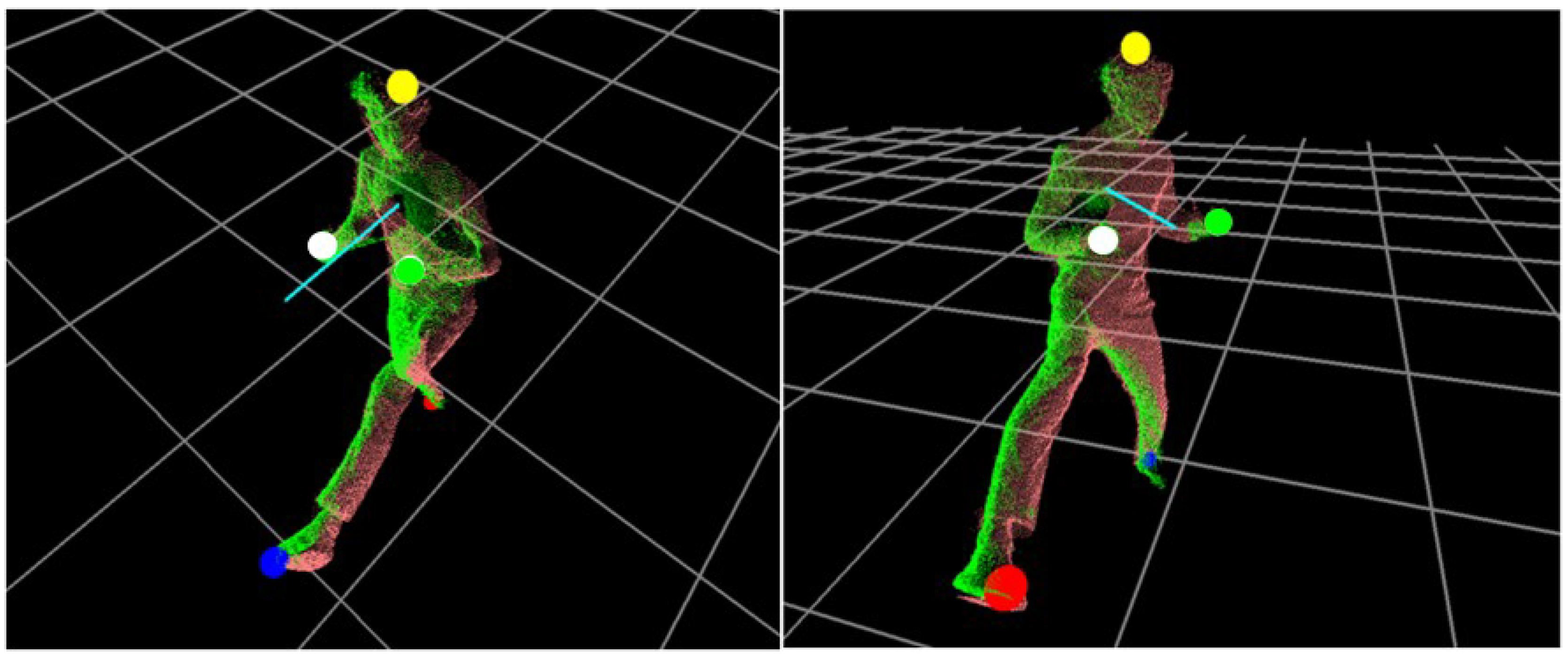
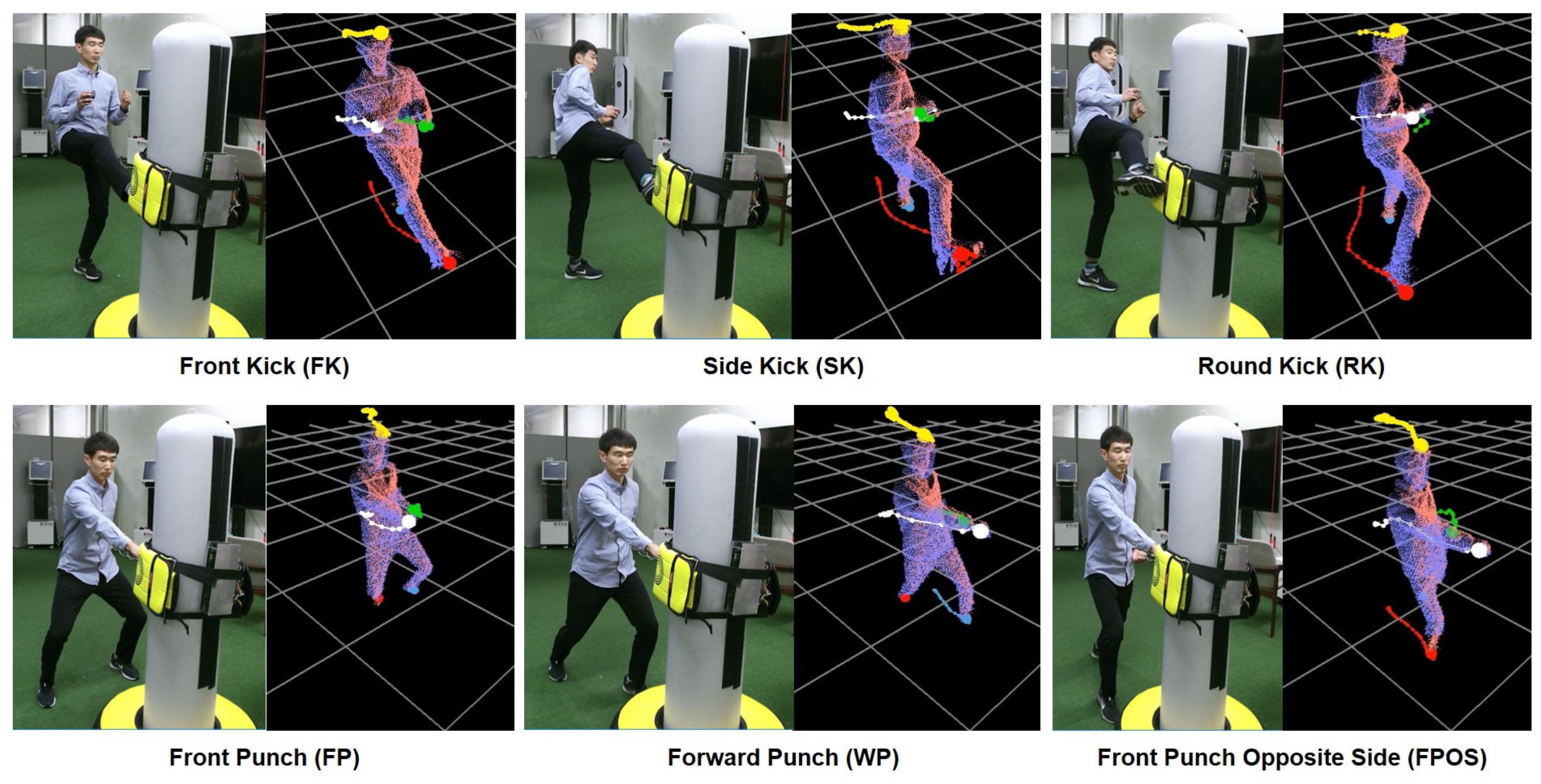
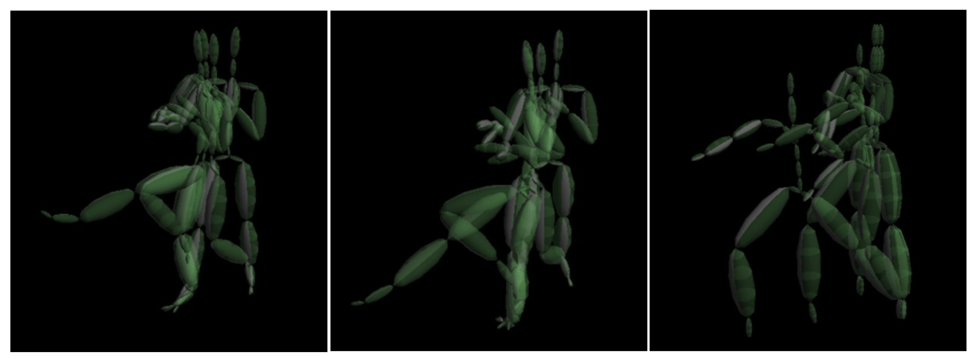
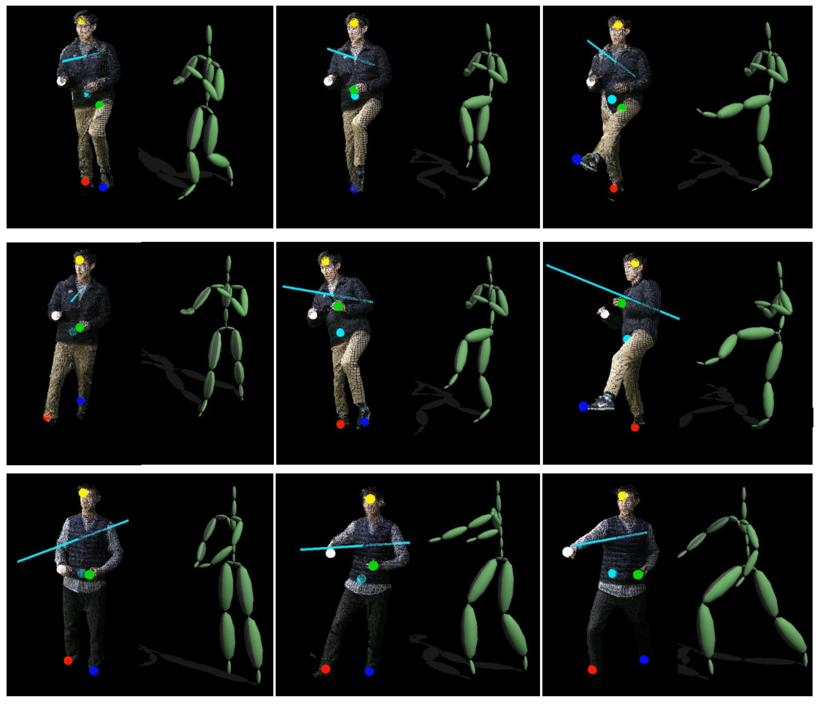
Figure 6 shows a set of
tracked and a body orientation represented by
. In our system,
is placed 300 mm higher from
for better recognition.
6. Conclusions
In this paper, we introduced a marker-less system for human pose estimation by detecting and tracking key body parts: Head, hands, and feet. Using multiple RGB-D cameras, our system minimizes the self-occlusion problems by unifying the depth data captured at different viewpoints into a single coordinate system. To accelerate the search process of the candidate points on the body parts, a quadtree-based graph is constructed from the RGB-D image, and the accumulative geodesic distances on the graph is used to select a set of extreme points on the key body parts. During the tracking process, these points are used as input parameters for motion analysis. Whenever there are tracking noises or failures, a Kalman filter-based method for noise removal and recovery is introduced to correct and expect the extreme positions. Unlike the previous approaches using a learning-based model, our approach does not reconstruct a full skeleton structure to estimate human poses from input data. Instead, the input poses are abstracted with a small set of extreme points, making the detecting and tracking process easier without solving the optimization problem for skeleton reconstruction. Using a small set of extremes as input data, our system can be applied to recognize a human action or to synthesize a motion sequence from a few key poses in real time. As demonstrated in the experimental results, our system shows a higher accuracy over the multi-Kinects system with more RGB-D cameras used.
The current system can be easily scalable by adding more RGB-D cameras as needed. For example, placing two more RGB-D cameras behind the user might provide better accuracy for the occluded poses in turning motion if the space and system cost are permitted. Using other RGB-D camera such as Intel RealSense [
3] was problematic due to noisy depth data and unstable support for the software library. Furthermore, our system is mainly designed to capture one user at a time. For the multi-person pose estimation, the current detection method can be exploited to extract multiple independent keys, possibly other than hands and feet, from the input images and to map each set of the keys to a different person.
The proposed system causes higher tracking errors when there are frequent crossing of hands and feet in an input pose. We are currently improving the tracking recovery process of such cases by analyzing the velocity gradients of hands and feet. In addition, there is no synchronization in the times between the input data received from multiple Kinect cameras that do not support a triggering signal. An external sync generator can be adopted with more sophisticated cameras; however, such a configuration increases the overall system cost, making the system less applicable for general users.


