
Trunk Motion System (TMS) Using Printed Body Worn Sensor (BWS) via Data Fusion Approach


 ,
,
Abstract
:1. Introduction
2. Materials and Methods
2.1. Materials
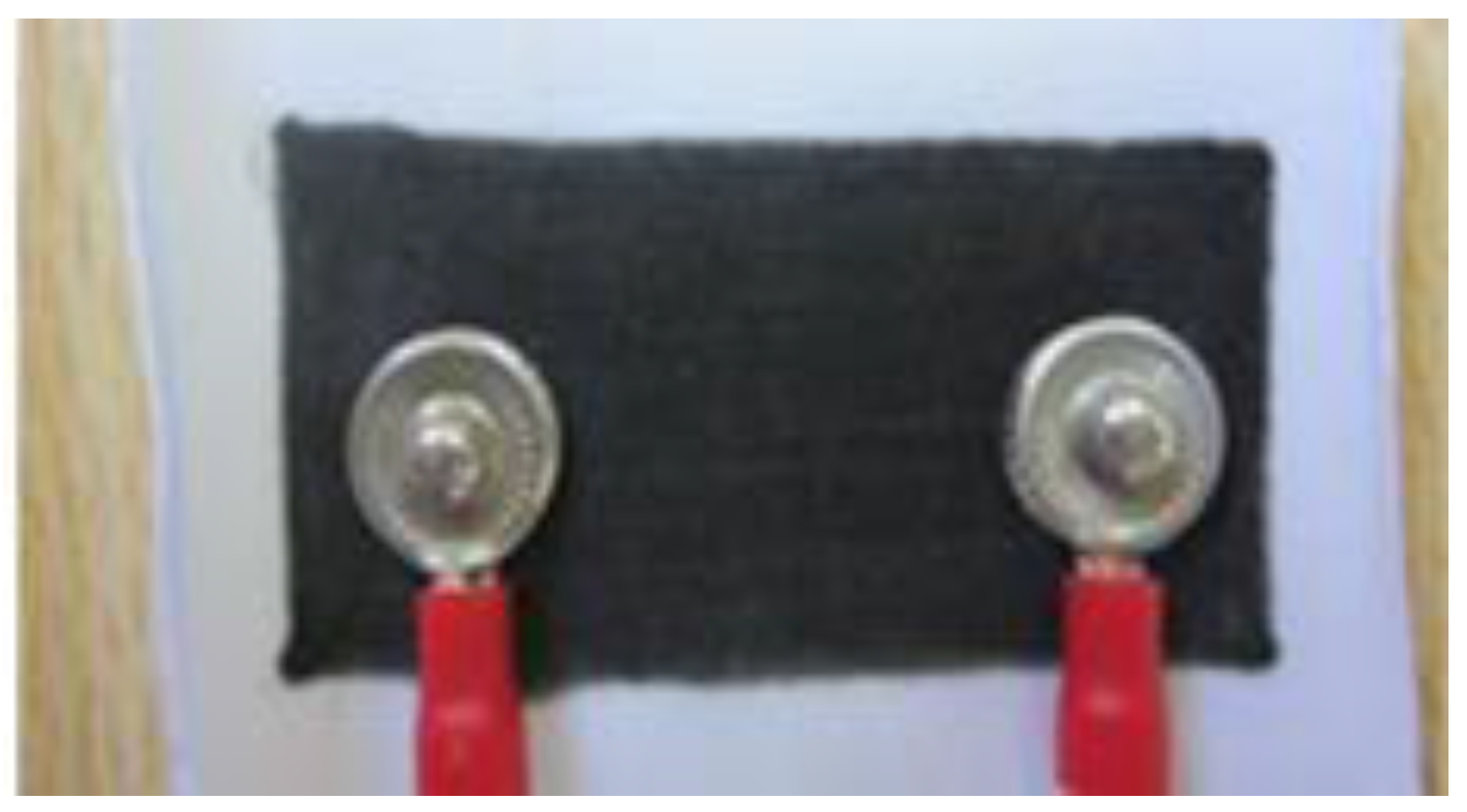
2.1.1. Body Worn Sensor (BWS)
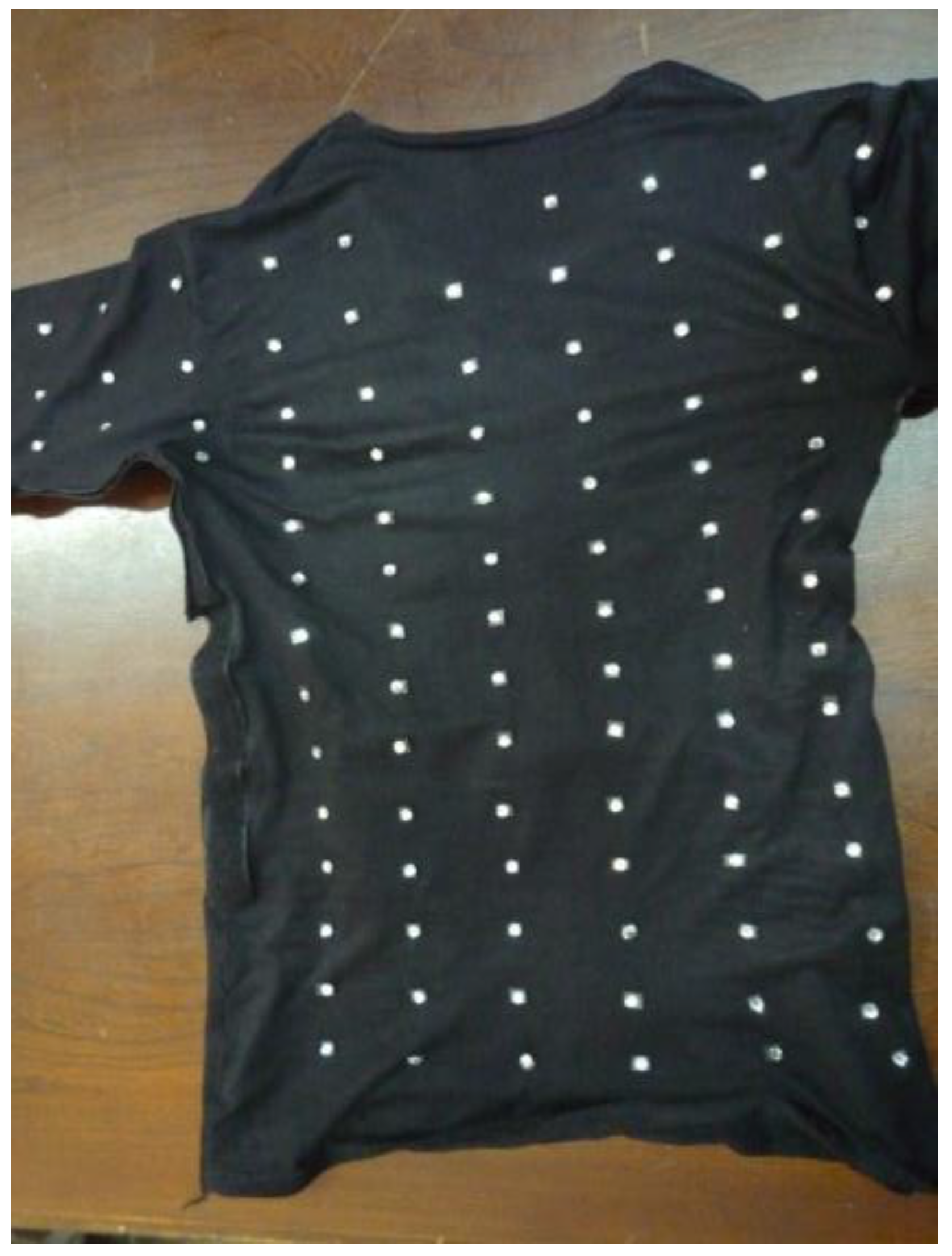
2.1.2. Stretchable Shirt
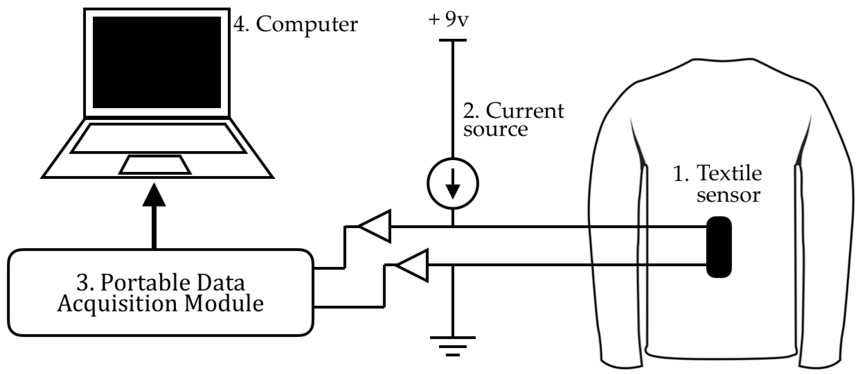
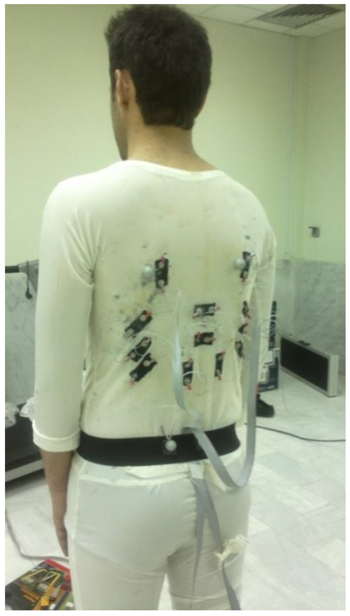
2.1.3. Measurement Setup
2.2. Methods
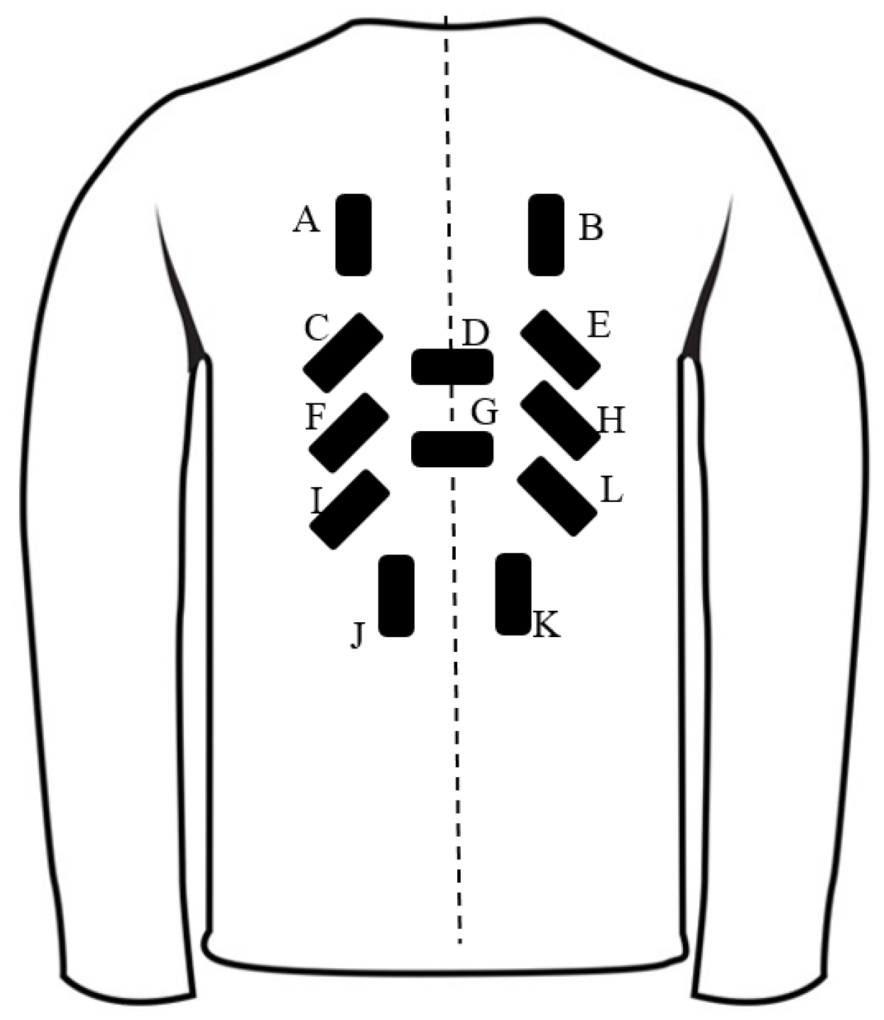
2.2.1. Determination of the Sensors’ Position
2.2.2. Calibration
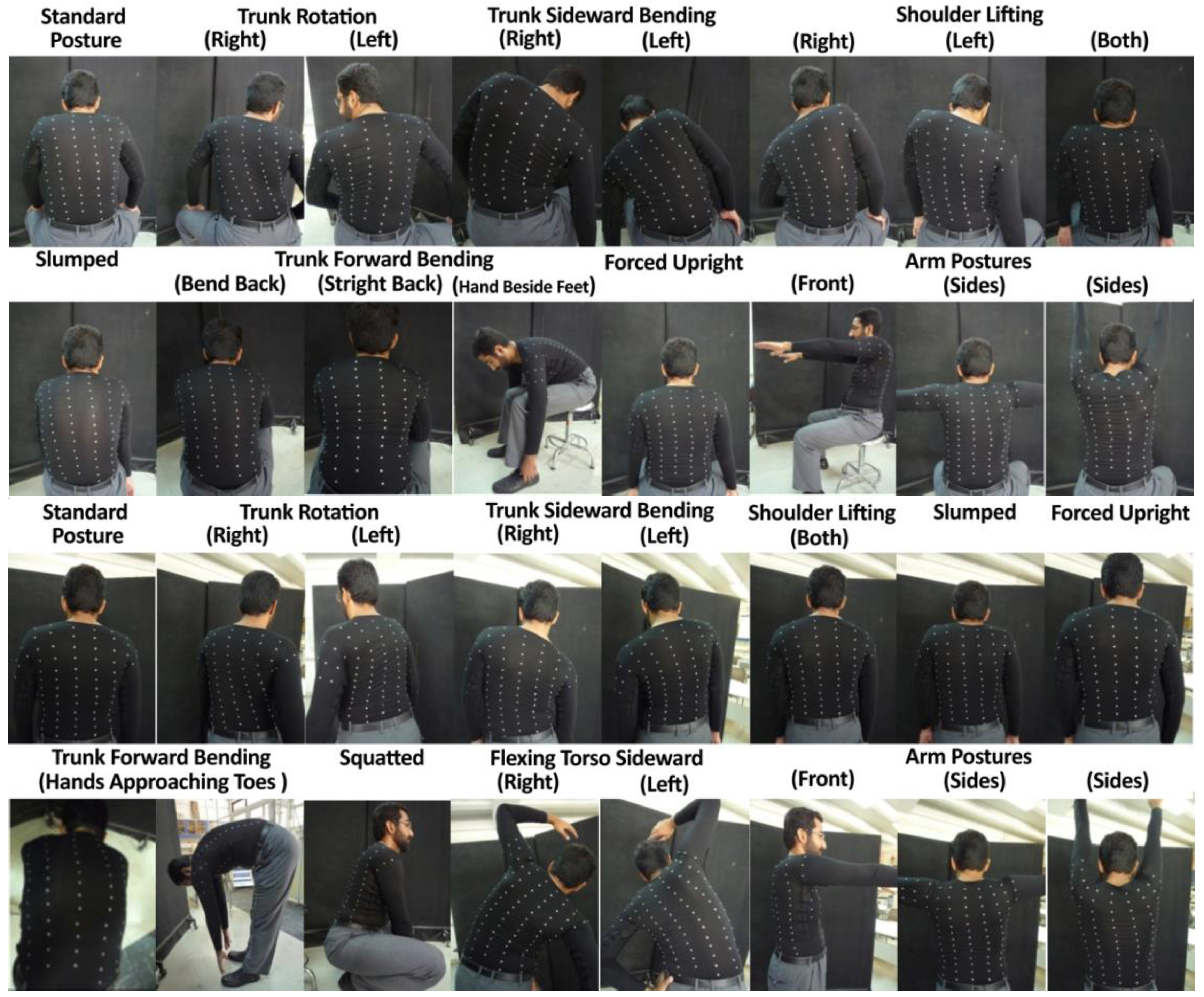
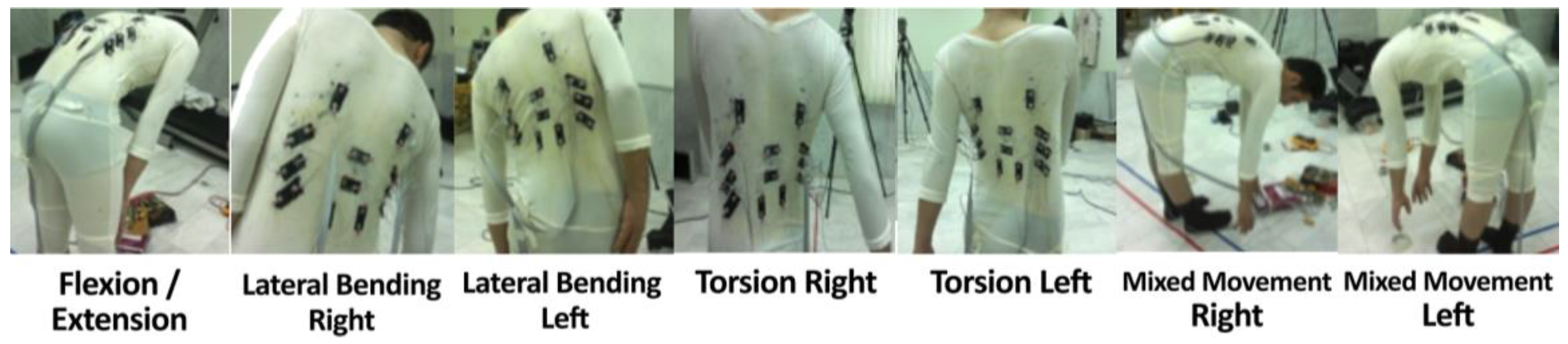
2.2.3. Experiment
2.2.4. Motion Analysis Strategy
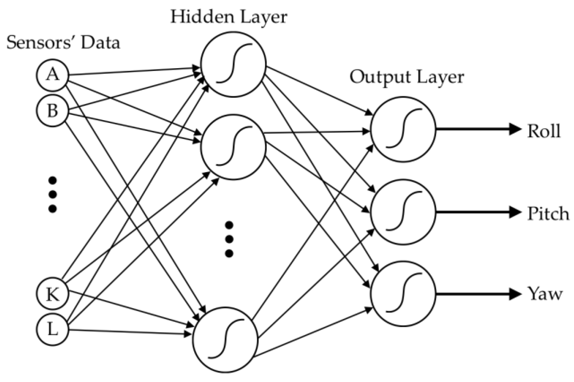
2.2.5. Data Fusion Process
3. Results
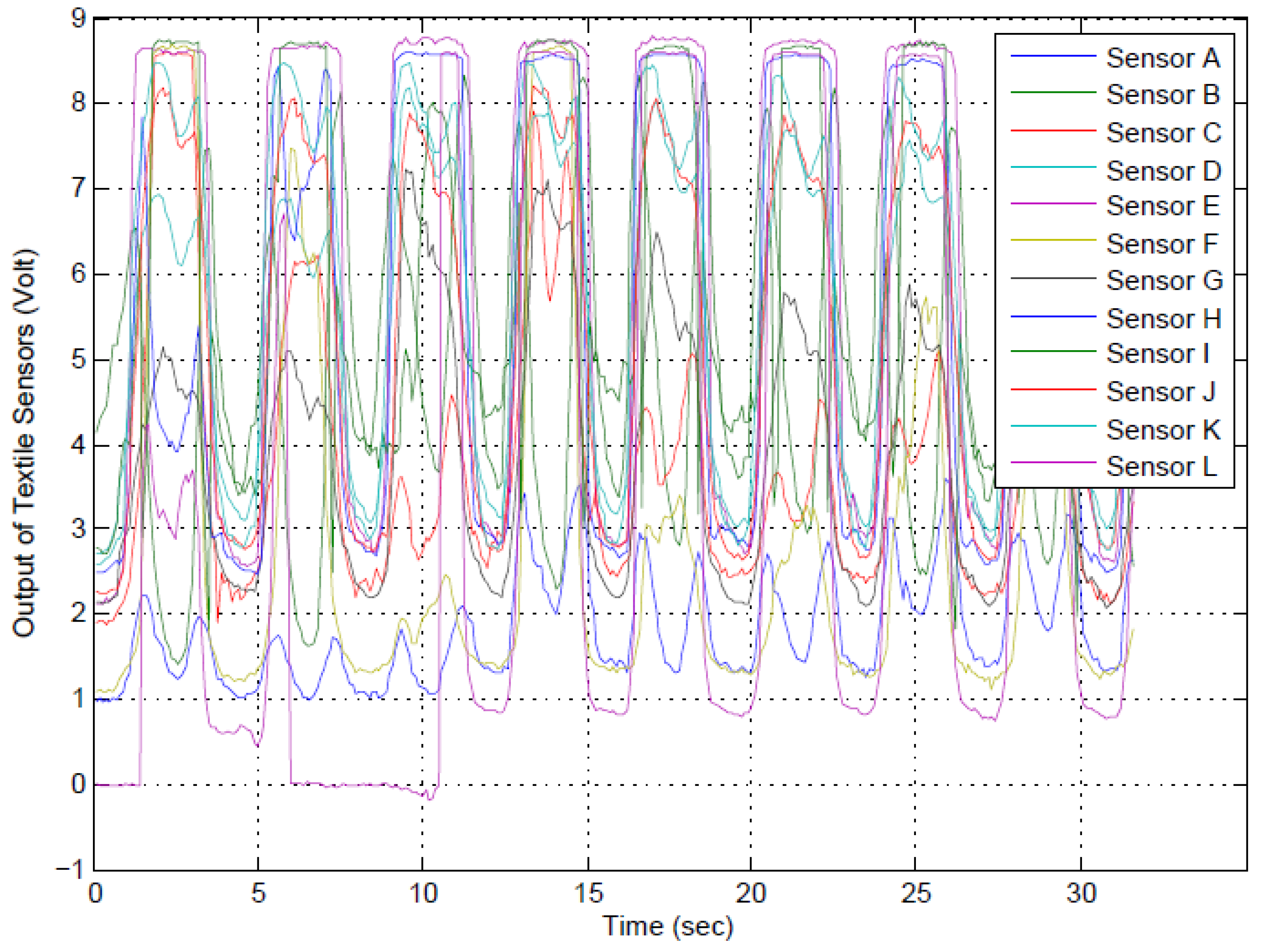
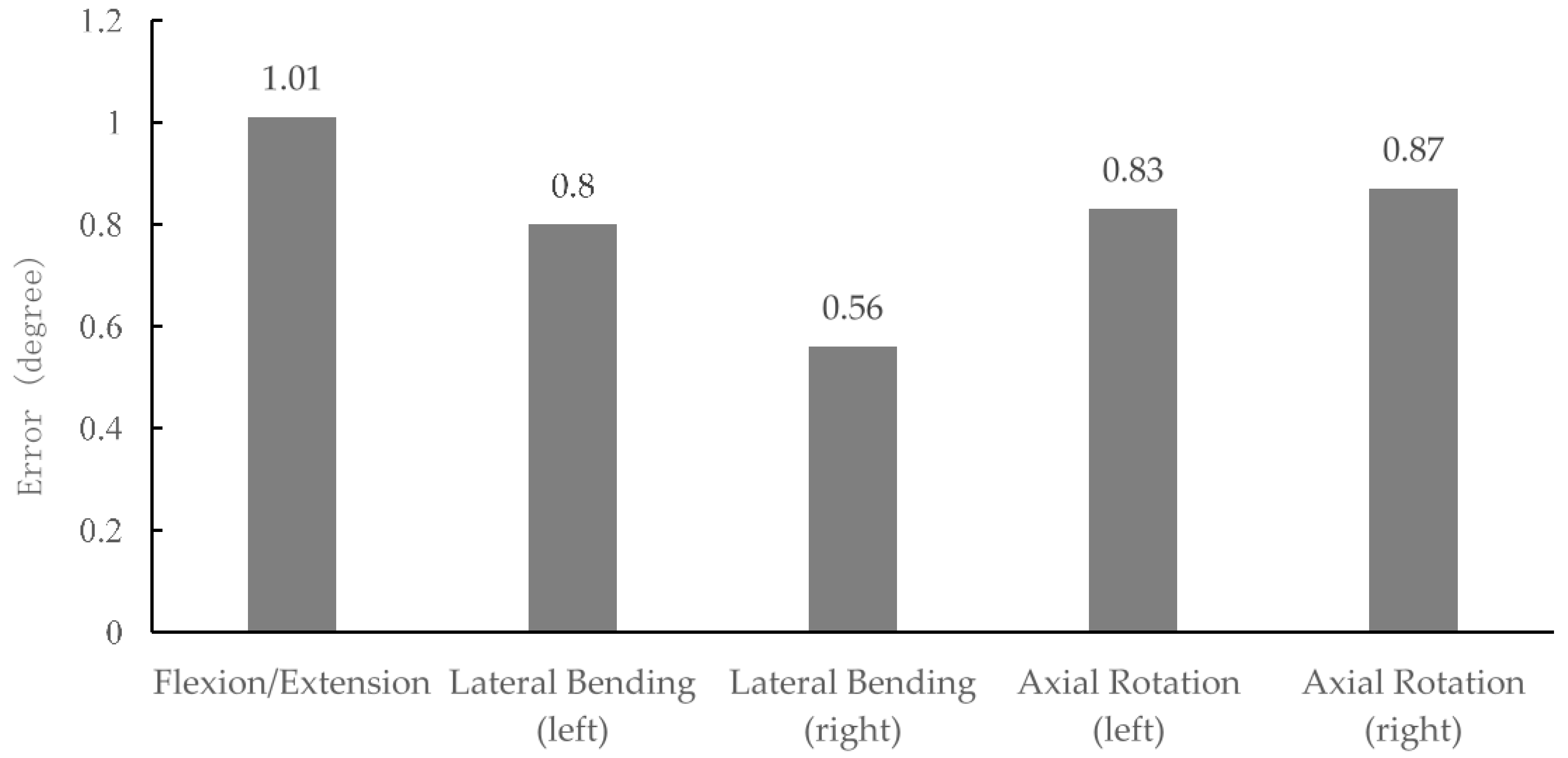
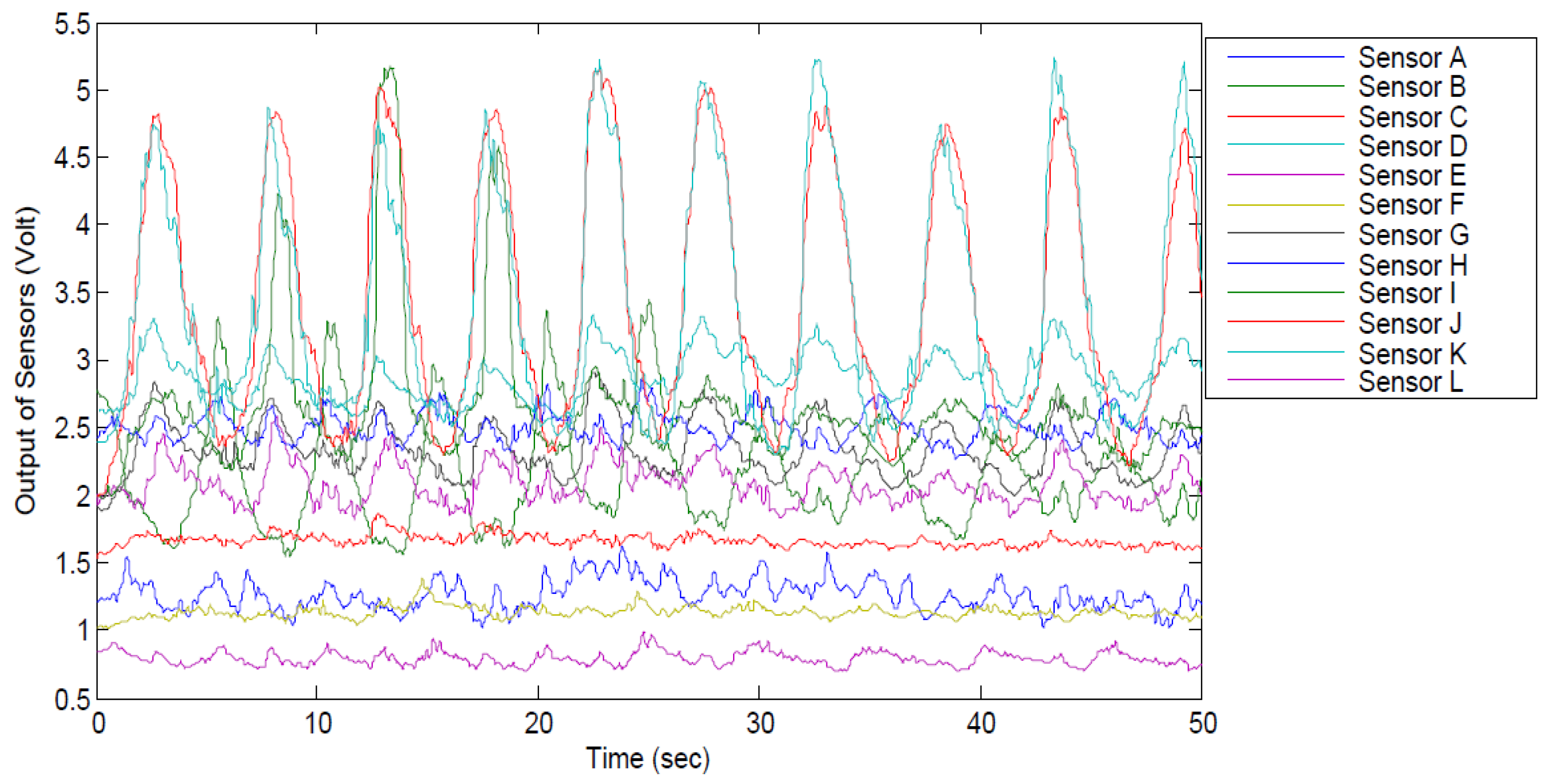
3.1. Planar Movements
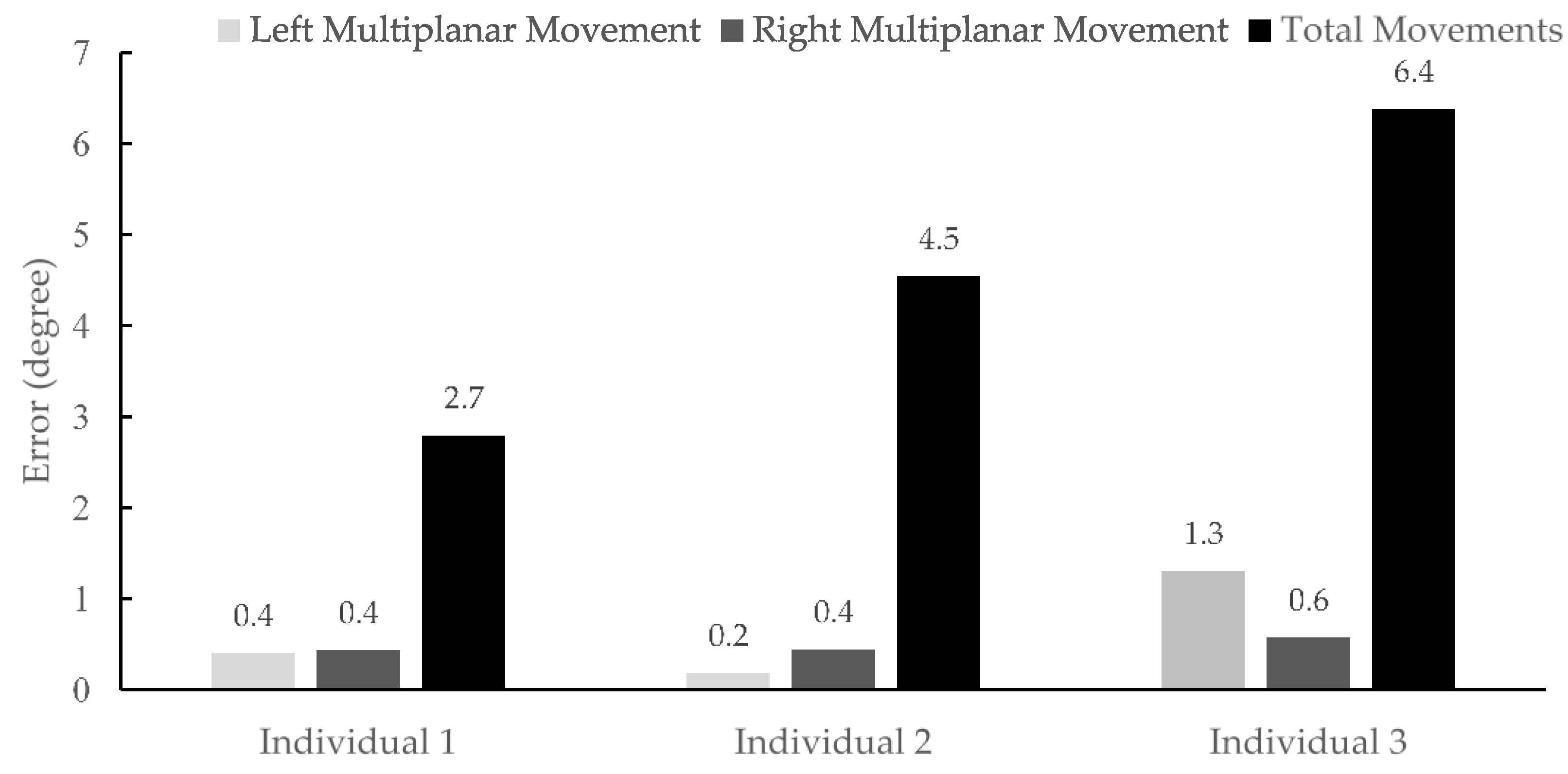
3.2. Multiplanar Movements
3.3. The Total Accuracy for TMS
3.4. Summary of Results
4. Discussion
5. Conclusions
Acknowledgments
Author Contributions
Conflicts of Interest
References
- Davatchi, F.; Jamshidi, A.R.; Banihashemi, A.T.; Gholami, J.; Forouzanfar, M.H.; Akhlaghi, M.; Barghamdi, M.; Noorolahzadeh, E.; Khabazi, A.R.; Salesi, M.; et al. Who-ilar copcord study (stage 1, urban study) in Iran. J. Rheumatol. 2008, 35, 1384–1390. [Google Scholar] [PubMed]
- Davatchi, F.; Tehrani Banihashemi, A.; Gholami, J.; Faezi, S.T.; Forouzanfar, M.H.; Salesi, M.; Karimifar, M.; Essalatmanesh, K.; Barghamdi, M.; Noorolahzadeh, E.; et al. The prevalence of musculoskeletal complaints in a rural area in iran: A who-ilar copcord study (stage 1, rural study) in Iran. Clin. Rheumatol. 2009, 28, 1267–1274. [Google Scholar] [CrossRef] [PubMed]
- Wong, W.Y.; Wong, M.S.; Lo, K.H. Clinical applications of sensors for human posture and movement analysis: A review. Prosthe. Orthot. Int. 2007, 31, 62–75. [Google Scholar] [CrossRef] [PubMed]
- Schwickert, L.; Becker, C.; Lindemann, U.; Marechal, C.; Bourke, A.; Chiari, L.; Helbostad, J.L.; Zijlstra, W.; Aminian, K.; Todd, C.; et al. Fall detection with body-worn sensors: A systematic review. Z. Gerontol. Geriatr. 2013, 46, 706–719. [Google Scholar] [CrossRef] [PubMed]
- Patel, S.; Park, H.; Bonato, P.; Chan, L.; Rodgers, M. A review of wearable sensors and systems with application in rehabilitation. J. Neuroeng. Rehabil. 2012, 9, 21. [Google Scholar] [CrossRef] [PubMed]
- Godfrey, A.; Conway, R.; Meagher, D.; OLaighin, G. Direct measurement of human movement by accelerometry. Med. Eng. Phys. 2008, 30, 1364–1386. [Google Scholar] [CrossRef] [PubMed]
- Bonato, P. Wearable sensors and systems. From enabling technology to clinical applications. IEEE Eng. Med. Biol. Mag. 2010, 29, 25–36. [Google Scholar] [CrossRef] [PubMed]
- Mokhlespour Esfahani, M.I.; Narimani, R.; Ramezanzadehkoldeh, M. A wearable respiratory plethysmography using flexible sensor. Int. J. Biomed. Eng. Technol. 2012, 11, 364–380. [Google Scholar] [CrossRef]
- Mokhlespour, M.I.; Zobeiri, O.; Akbari, A.; Milani, Y.; Narimani, R.; Moshiri, B.; Parnianpour, M. Sharif-human movement instrumentation system (SHARIF-HMIS) for daily activities. In Proceedings of the Iranian Conference of Biomedical Engineering (ICBME), Tehran, Iran, 20–21 December 2012; pp. 143–148.
- Stoppa, M.; Chiolerio, A. Wearable electronics and smart textiles: A critical review. Sensors 2014, 14, 11957–11992. [Google Scholar] [CrossRef] [PubMed]
- Bergmann, J.H.; McGregor, A.H. Body-worn sensor design: What do patients and clinicians want? Ann. Biomed. Eng. 2011, 39, 2299–2312. [Google Scholar] [CrossRef] [PubMed]
- Bergmann, J.H.; Chandaria, V.; McGregor, A. Wearable and implantable sensors: The patient’s perspective. Sensors 2012, 12, 16695–16709. [Google Scholar] [CrossRef] [PubMed]
- Coley, B.; Jolles, B.M.; Farron, A.; Bourgeois, A.; Nussbaumer, F.; Pichonnaz, C.; Aminian, K. Outcome evaluation in shoulder surgery using 3D kinematics sensors. Gait Posture 2007, 25, 523–532. [Google Scholar] [CrossRef] [PubMed]
- Skog, I.; Handel, P.; Nilsson, J.O.; Rantakokko, J. Zero-velocity detection-an algorithm evaluation. IEEE Trans. Biomed. Eng. 2010, 57, 2657–2666. [Google Scholar] [CrossRef] [PubMed]
- Schepers, H.M.; Koopman, H.F.; Veltink, P.H. Ambulatory assessment of ankle and foot dynamics. IEEE Trans. Biomed. Eng. 2007, 54, 895–902. [Google Scholar] [CrossRef] [PubMed]
- Favre, J.; Aissaoui, R.; Jolles, B.M.; de Guise, J.A.; Aminian, K. Functional calibration procedure for 3D knee joint angle description using inertial sensors. J. Biomech. 2009, 42, 2330–2335. [Google Scholar] [CrossRef] [PubMed]
- Roetenberg, D.; Luinge, H.J.; Baten, C.T.; Veltink, P.H. Compensation of magnetic disturbances improves inertial and magnetic sensing of human body segment orientation. IEEE Trans. Neural Syst. Rehabil. Eng. 2005, 13, 395–405. [Google Scholar] [CrossRef] [PubMed]
- Roetenberg, D.; Luinge, H.; Slycke, P. Xsens MVN: Full 6Dof Human Motion Tracking Using Miniature Inertial Sensors; Xsens Company: Enschede, Netherlands, 2013; pp. 1–9. [Google Scholar]
- Hosseinzadegan, H.; Pierron, O.N.; Hosseinian, E. Accurate modeling of air shear damping of a silicon lateral rotary micro-resonator for mems environmental monitoring applications. Sens. Actuators A Phys. 2014, 216, 342–348. [Google Scholar] [CrossRef]
- Scilingo, E.P.; Lorussi, F.; Mazzoldi, A.; de Rossi, D. Strain-sensing fabrics for wearable kinaesthetic-like systems. IEEE Sens. J. 2003, 3, 460–467. [Google Scholar] [CrossRef]
- Wu, J.; Zhou, D.; Too, C.O.; Wallace, G.G. Conducting polymer coated lycra. Synth. Met. 2005, 155, 698–701. [Google Scholar] [CrossRef]
- Wang, L.J.; Lin, T.; Wang, X.G. Characterization and application of conducting polymer coated textiles. Int. J. Mod. Phys. B 2009, 23, 1241–1247. [Google Scholar] [CrossRef]
- Pacelli, M.; Loriga, G.; Taccini, N.; Paradiso, R. Sensing fabrics for monitoring physiological and biomechanical variables: E-textile solutions. In Proceedings of the 2006 3rd IEEE/EMBS International Summer School on Medical Devices and Biosensors, Boston, MA, USA, 4–6 September 2006; pp. 1–4.
- Amft, O.; Junker, H.; Lukowicz, P.; Troster, G.; Schuster, C. Sensing muscle activities with body-worn sensors. In Proceedings of the BSN 2006 International Workshop on Wearable and Implantable Body Sensor Networks, Cambridge, MA, USA, 3–5 April 2006; pp. 138–141.
- Bartalesi, R.; Lorussi, F.; Tognetti, A.; Tesconi, M.; Zupone, G.; Carbonaro, N.; de Rossi, D. Wearable kinesthetic sensors for body posture and movement analysis. J. Biomech. 2007, 40, S425–S427. [Google Scholar] [CrossRef]
- Farringdon, J.; Moore, A.J.; Tilbury, N.; Church, J.; Biemond, P.D. Wearable sensor badge and sensor jacket for context awareness. In Proceedings of the Third International Symposium on Wearable Computers: Digest of Papers, San Francisco, CA, USA, 18–19 October 1999; pp. 107–113.
- Harms, H.; Amft, O.; Trster, G.; Roggen, D. Smash: A distributed sensing and processing garment for the classification of upper body postures. In Proceedings of the ICST 3rd International Conference on Body Area Networks, Tempe, AZ, USA, 13–17 March 2008; pp. 1–8.
- Mattmann, C.; Clemens, F.; Troster, G. Sensor for measuring strain in textile. Sensors 2008, 8, 3719–3732. [Google Scholar] [CrossRef] [PubMed]
- Mokhlespour Esfahani, M.I.; Taghinedjad, S.; Mottaghitalab, V.; Narimani, R.; Parnianpour, M. Novel printed body worn sensor for measuring the human movement orientation. Sens. Rev. 2016, 36, 321–331. [Google Scholar] [CrossRef]
- Schrack, J.A.; Cooper, R.; Koster, A.; Shiroma, E.J.; Murabito, J.M.; Rejeski, W.J.; Ferrucci, L.; Harris, T.B. Assessing daily physical activity in older adults: Unraveling the complexity of monitors, measures, and methods. J. Gerontol. Ser. A 2016, 71, 1039–1048. [Google Scholar] [CrossRef] [PubMed]
- Fortune, E.; Lugade, V.A.; Kaufman, K.R. Posture and movement classification: The comparison of tri-axial accelerometer numbers and anatomical placement. J. Biomech. Eng. 2014, 136, 051003. [Google Scholar] [CrossRef] [PubMed]
- Boerema, S.T.; van Velsen, L.; Schaake, L.; Tönis, T.M.; Hermens, H.J. Optimal sensor placement for measuring physical activity with a 3D accelerometer. Sensors 2014, 14, 3188–3206. [Google Scholar] [CrossRef] [PubMed]
- Cleland, I.; Kikhia, B.; Nugent, C.; Boytsov, A.; Hallberg, J.; Synnes, K.; McClean, S.; Finlay, D. Optimal placement of accelerometers for the detection of everyday activities. Sensors 2013, 13, 9183–9200. [Google Scholar] [CrossRef] [PubMed]
- Schall, M.C., Jr.; Fethke, N.B.; Chen, H. Evaluation of four sensor locations for physical activity assessment. Appl. Ergon. 2016, 53, 103–109. [Google Scholar] [CrossRef] [PubMed]
- Tormene, P.; Bartolo, M.; De Nunzio, A.M.; Fecchio, F.; Quaglini, S.; Tassorelli, C.; Sandrini, G. Estimation of human trunk movements by wearable strain sensors and improvement of sensor’s placement on intelligent biomedical clothes. Biomed. Eng. Online 2012, 11, 95. [Google Scholar] [CrossRef] [PubMed]
- Lorussi, F.; Rocchia, W.; Scilingo, E.P.; Tognetti, A.; de Rossi, D. Wearable, redundant fabric-based sensor arrays for reconstruction of body segment posture. IEEE Sens. J. 2004, 4, 807–818. [Google Scholar] [CrossRef]
- Tognetti, A.; Lorussi, F.; Bartalesi, R.; Quaglini, S.; Tesconi, M.; Zupone, G.; de Rossi, D. Wearable kinesthetic system for capturing and classifying upper limb gesture in post-stroke rehabilitation. J. Neuroeng. Rehabil. 2005, 2, 8. [Google Scholar] [CrossRef] [PubMed]
- Yang, C.-M.; Lin, Z.-S.; Hu, C.-L.; Chen, Y.-S.; Ke, L.-Y.; Chen, Y.-R. A novel dynamic sensing of wearable digital textile sensor with body motion analysis. In Proceedings of the 32nd Annual International Conference of the IEEE EMBS, Buenos Aires, Argentina, 1–4 September 2010.
- Wong, W.Y.; Wong, M.S. Smart garment for trunk posture monitoring: A preliminary study. Scoliosis 2008, 3, 7. [Google Scholar] [CrossRef] [PubMed]
- Tognetti, A.; Lorussi, F.; Mura, G.D.; Carbonaro, N.; Pacelli, M.; Paradiso, R.; Rossi, D.D. New generation of wearable goniometers for motion capture systems. J. Neuroeng. Rehabil. 2014, 11, 56. [Google Scholar] [CrossRef] [PubMed]
- Fleury, A.; Sugar, M.; Chau, T. E-textiles in clinical rehabilitation: A scoping review. Electronics 2015, 4, 173–203. [Google Scholar] [CrossRef]
- Sardini, E.; Serpelloni, M.; Pasqui, V. Daylong sitting posture measurement with a new wearable system for at home body movement monitoring. In Proceedings of the IEEE International Instrumentation and Measurement Technology Conference, Pisa, Italy, 11–14 May 2015; pp. 652–657.
- Gibbs, P.T.; Asada, H.H. Wearable conductive fiber sensors for multi-axis human joint angle measurements. J. Neuroeng. Rehabil. 2005, 2, 7. [Google Scholar] [CrossRef] [PubMed]
- Saggio, G.; Sbernini, L. New scenarios in human trunk posture measurements for clinical applications. In Proceedings of the 2011 IEEE International Workshop on Medical Measurements and Applications Proceedings (MeMeA), Bary, Italy, 30–31 May 2011; pp. 13–17.
- Chen, L.; Hoey, J.; Nugent, C.D.; Cook, D.J.; Yu, Z. Sensor-based activity recognition. IEEE Trans. Syst. Man Cybern. Part C 2012, 42, 790–808. [Google Scholar] [CrossRef]
- Wu, G.; van der Helm, F.C.T.; Veeger, H.E.J.; Makhsous, M.; Van Roy, P.; Anglin, C.; Nagels, J.; Karduna, A.R.; McQuade, K.; Wang, X.; et al. ISB recommendation on definitions of joint coordinate systems of various joints for the reporting of human joint motion—Part II: Shoulder, elbow, wrist and hand. J. Biomech. 2005, 38, 981–992. [Google Scholar] [CrossRef] [PubMed]
- Siciliano, B.; Khatib, O. Springer Handbook of Robotics; Springer: Berlin, Germany, 2008. [Google Scholar]
- More, J.J. The levenberg-marquardt algorithm: Implementation and theory. In Numerical Analysis; Watson, G.A., Ed.; Springer: Berlin/Heidelberg, Germany, 1978; pp. 105–116. [Google Scholar]
- Attal, F.; Mohammed, S.; Dedabrishvili, M.; Chamroukhi, F.; Oukhellou, L.; Amirat, Y. Physical human activity recognition using wearable sensors. Sensors 2015, 15, 31314–31338. [Google Scholar] [CrossRef] [PubMed]
- Peetoom, K.K.; Lexis, M.A.; Joore, M.; Dirksen, C.D.; De Witte, L.P. Literature review on monitoring technologies and their outcomes in independently living elderly people. Disabil. Rehabil. Assist. Technol. 2015, 10, 271–294. [Google Scholar] [CrossRef] [PubMed]
- Dunne, L. Beyond the second skin: An experimental approach to addressing garment style and fit variables in the design of sensing garments. Int. J. Fash. Des. Technol. Educ. 2010, 3, 109–117. [Google Scholar] [CrossRef]
- Marras, W.S.; Fathallah, F.A.; Miller, R.J.; Davis, S.W.; Mirka, G.A. Accuracy of a three-dimensional lumbar motion monitor for recording dynamic trunk motion characteristics. Int. J. Ind. Ergon. 1992, 9, 75–87. [Google Scholar] [CrossRef]
- Szelitzky, E.; Kuklyte, J.; Mândru, D.; O’Connor, N. Low cost angular displacement sensors for biomechanical applications—A review. J. Biomed. Eng. Technol. 2014, 2, 21–28. [Google Scholar]
- Godwin, A.; Agnew, M.; Stevenson, J. Accuracy of inertial motion sensors in static, quasistatic, and complex dynamic motion. J. Biomech. Eng. 2009, 131, 114501–114505. [Google Scholar] [CrossRef] [PubMed]
- Bastani, K.; Kim, S.; Kong, Z.J.; Nussbaum, M.A.; Huang, W. Online classification and sensor selection optimization with applications to human material handling tasks using wearable sensing technologies. IEEE Trans. Hum.-Mach. Syst. 2016. [Google Scholar] [CrossRef]
- Castano, L.M.; Flatau, A.B. Smart fabric sensors and e-textile technologies: A review. Smart Mater. Struct. 2014, 23, 053001. [Google Scholar] [CrossRef]


| Characteristics | Max Strain | Max Strain Velocity | Linearity Error | Hysteresis Error | Repeatability Error | Relaxation Behavior |
|---|---|---|---|---|---|---|
| Amount | 50% | 400 (mm/min) | 2% | 8% | 7% | 11% |
| Test | Input | Output | Neuron | Samples | RMSE 1 | R 2 | |
|---|---|---|---|---|---|---|---|
| Flexion/Extension | 12 | 1 | 40 | Training | 1750 | 0.65 | 0.998 |
| Validation | 375 | 1.14 | 0.994 | ||||
| Test | 375 | 1.01 | 0.995 | ||||
| Lateral bending (left) | 12 | 1 | 40 | Training | 1750 | 0.46 | 0.999 |
| Validation | 375 | 1.06 | 0.997 | ||||
| Test | 375 | 0.80 | 0.998 | ||||
| Lateral bending (right) | 12 | 1 | 40 | Training | 1750 | 0.35 | 0.999 |
| Validation | 375 | 0.65 | 0.998 | ||||
| Test | 375 | 0.56 | 0.999 | ||||
| Axial rotation (left) | 12 | 1 | 40 | Training | 1750 | 0.85 | 0.999 |
| Validation | 375 | 0.61 | 0.999 | ||||
| Test | 375 | 0.82 | 0.999 | ||||
| Axial rotation (right) | 12 | 1 | 40 | Training | 1750 | 0.40 | 0.999 |
| Validation | 375 | 0.79 | 0.998 | ||||
| Test | 375 | 0.87 | 0.998 |
| Test | Input | Output | Neuron | Samples | RMSE 1 | R 2 | |
|---|---|---|---|---|---|---|---|
| Left multiplanar movement for Participant 1 | 12 | 3 | 90 | Training | 874 | 0.05 | 0.999 |
| Validation | 188 | 0.37 | 0.999 | ||||
| Test | 188 | 0.40 | 0.999 | ||||
| Right multiplanar movement for Participant 1 | 12 | 3 | 40 | Training | 700 | 0.24 | 0.999 |
| Validation | 150 | 0.38 | 0.999 | ||||
| Test | 150 | 0.43 | 0.999 | ||||
| Left multiplanar movement for Participant 2 | 12 | 3 | 60 | Training | 688 | 0.06 | 0.999 |
| Validation | 148 | 0.14 | 0.999 | ||||
| Test | 148 | 0.18 | 0.999 | ||||
| Right multiplanar movement for Participant 2 | 12 | 3 | 60 | Training | 1050 | 0.22 | 0.999 |
| Validation | 225 | 0.39 | 0.998 | ||||
| Test | 225 | 0.44 | 0.998 | ||||
| Left multiplanar Movement for Participant 3 | 12 | 3 | 90 | Training | 1750 | 0.72 | 0.999 |
| Validation | 375 | 1.23 | 0.997 | ||||
| Test | 375 | 1.30 | 0.996 | ||||
| Right multiplanar movement for Participant 3 | 12 | 3 | 90 | Training | 1750 | 0.35 | 0.999 |
| Validation | 375 | 0.57 | 0.999 | ||||
| Test | 375 | 0.57 | 0.999 |
| Test | Input | Output | Neuron | Sample | RMSE 1 | R 2 | |
|---|---|---|---|---|---|---|---|
| Participant 1 | 12 | 3 | 60 | Training | 10,324 | 2.67 | 0.979 |
| Validation | 2213 | 2.97 | 0.976 | ||||
| Test | 2213 | 2.8 | 0.977 | ||||
| Participant 2 | 12 | 3 | 60 | Training | 8738 | 4.14 | 0.973 |
| Validation | 1873 | 4.51 | 0.970 | ||||
| Test | 1873 | 4.54 | 0.968 | ||||
| Participant 3 | 12 | 3 | 45 | Training | 11,024 | 5.94 | 0.938 |
| Validation | 2363 | 6.22 | 0.933 | ||||
| Test | 2363 | 6.38 | 0.932 |
© 2017 by the authors; licensee MDPI, Basel, Switzerland. This article is an open access article distributed under the terms and conditions of the Creative Commons Attribution (CC-BY) license (http://creativecommons.org/licenses/by/4.0/).
Share and Cite
Mokhlespour Esfahani, M.I.; Zobeiri, O.; Moshiri, B.; Narimani, R.; Mehravar, M.; Rashedi, E.; Parnianpour, M. Trunk Motion System (TMS) Using Printed Body Worn Sensor (BWS) via Data Fusion Approach. Sensors 2017, 17, 112. https://doi.org/10.3390/s17010112
Mokhlespour Esfahani MI, Zobeiri O, Moshiri B, Narimani R, Mehravar M, Rashedi E, Parnianpour M. Trunk Motion System (TMS) Using Printed Body Worn Sensor (BWS) via Data Fusion Approach. Sensors. 2017; 17(1):112. https://doi.org/10.3390/s17010112
Chicago/Turabian StyleMokhlespour Esfahani, Mohammad Iman, Omid Zobeiri, Behzad Moshiri, Roya Narimani, Mohammad Mehravar, Ehsan Rashedi, and Mohamad Parnianpour. 2017. "Trunk Motion System (TMS) Using Printed Body Worn Sensor (BWS) via Data Fusion Approach" Sensors 17, no. 1: 112. https://doi.org/10.3390/s17010112
APA StyleMokhlespour Esfahani, M. I., Zobeiri, O., Moshiri, B., Narimani, R., Mehravar, M., Rashedi, E., & Parnianpour, M. (2017). Trunk Motion System (TMS) Using Printed Body Worn Sensor (BWS) via Data Fusion Approach. Sensors, 17(1), 112. https://doi.org/10.3390/s17010112