Article

High-Accuracy, Compact Scanning Method and Circuit for Resistive Sensor Arrays
Department of Electronic Engineering, Hanyang University, 222 Wangsimni-ro, Deongdong-gu, Seoul 04763, Korea
*
Author to whom correspondence should be addressed.
Sensors 2016, 16(2), 155; https://doi.org/10.3390/s16020155
Submission received: 26 November 2015 / Revised: 15 January 2016 / Accepted: 21 January 2016 / Published: 26 January 2016
(This article belongs to the Section Physical Sensors)

Abstract

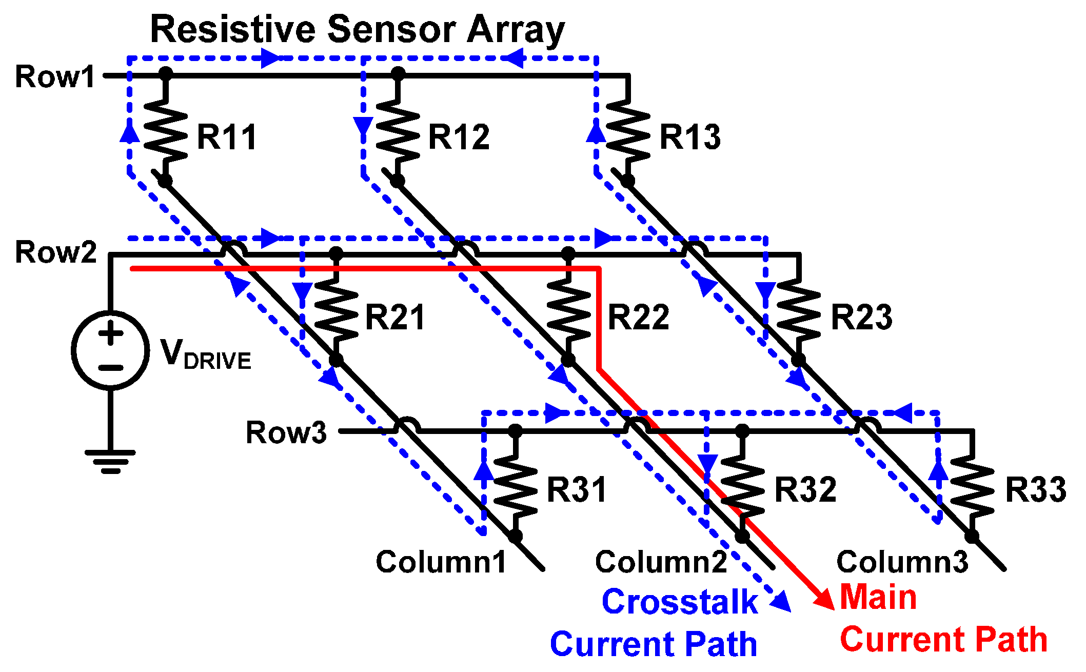
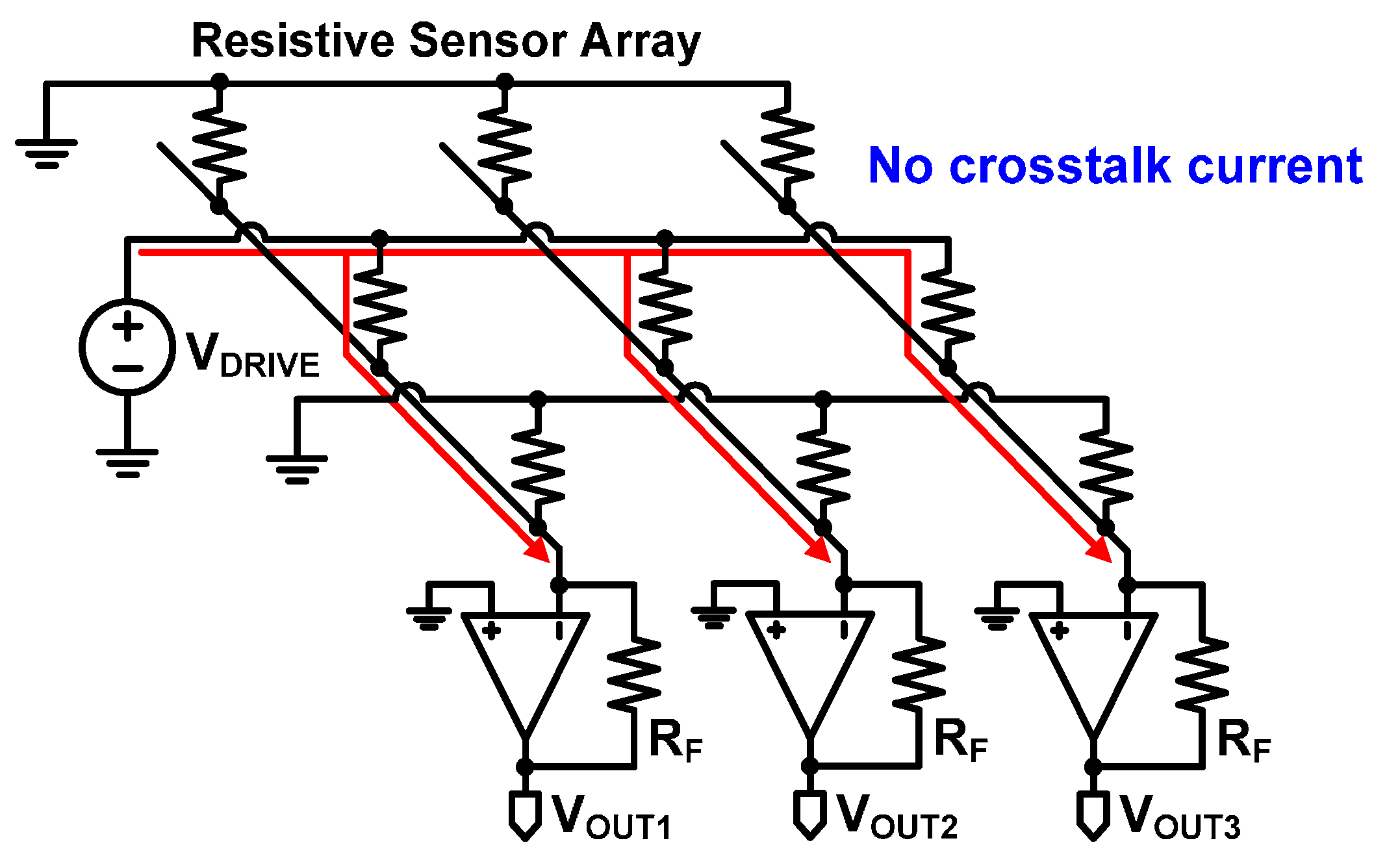
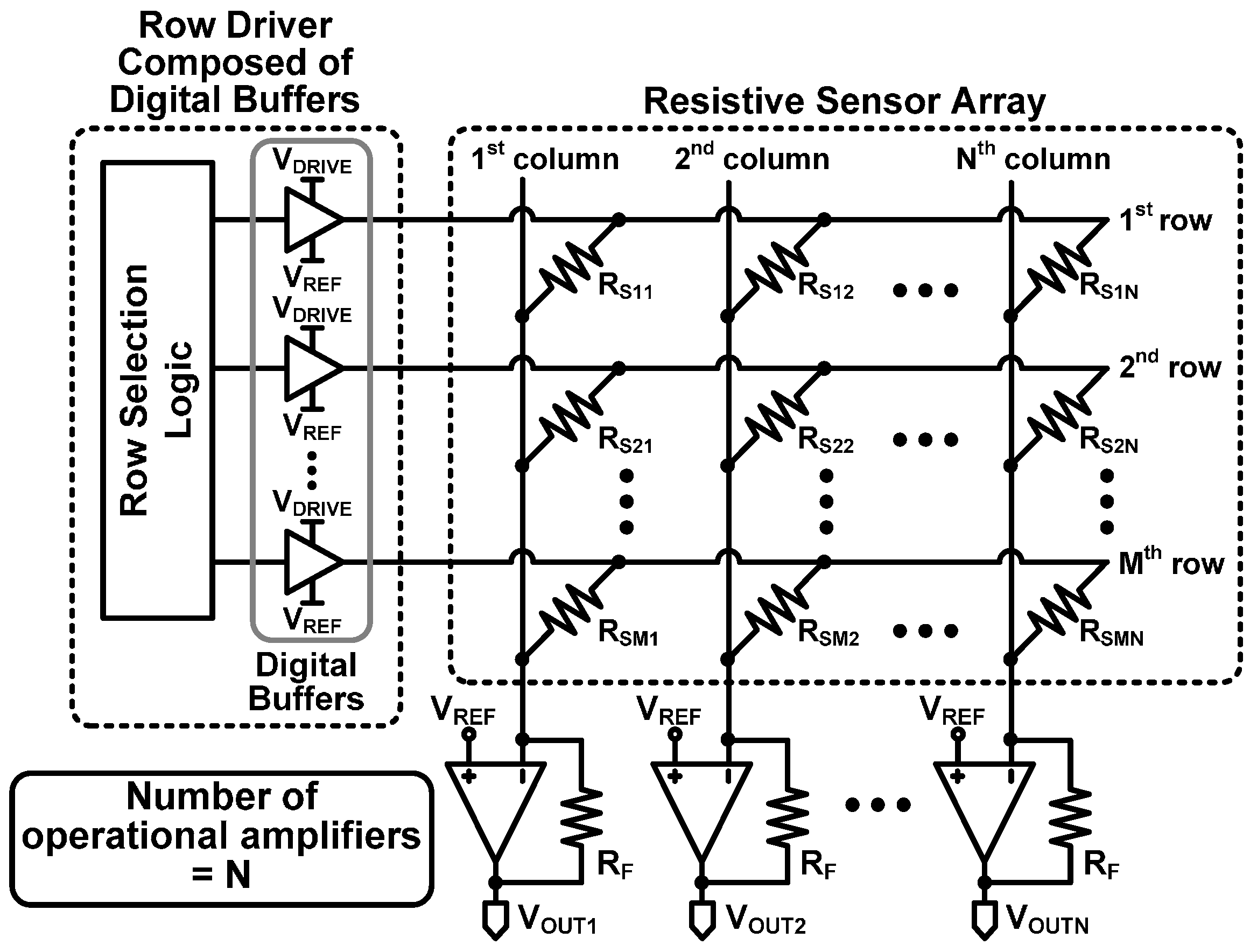
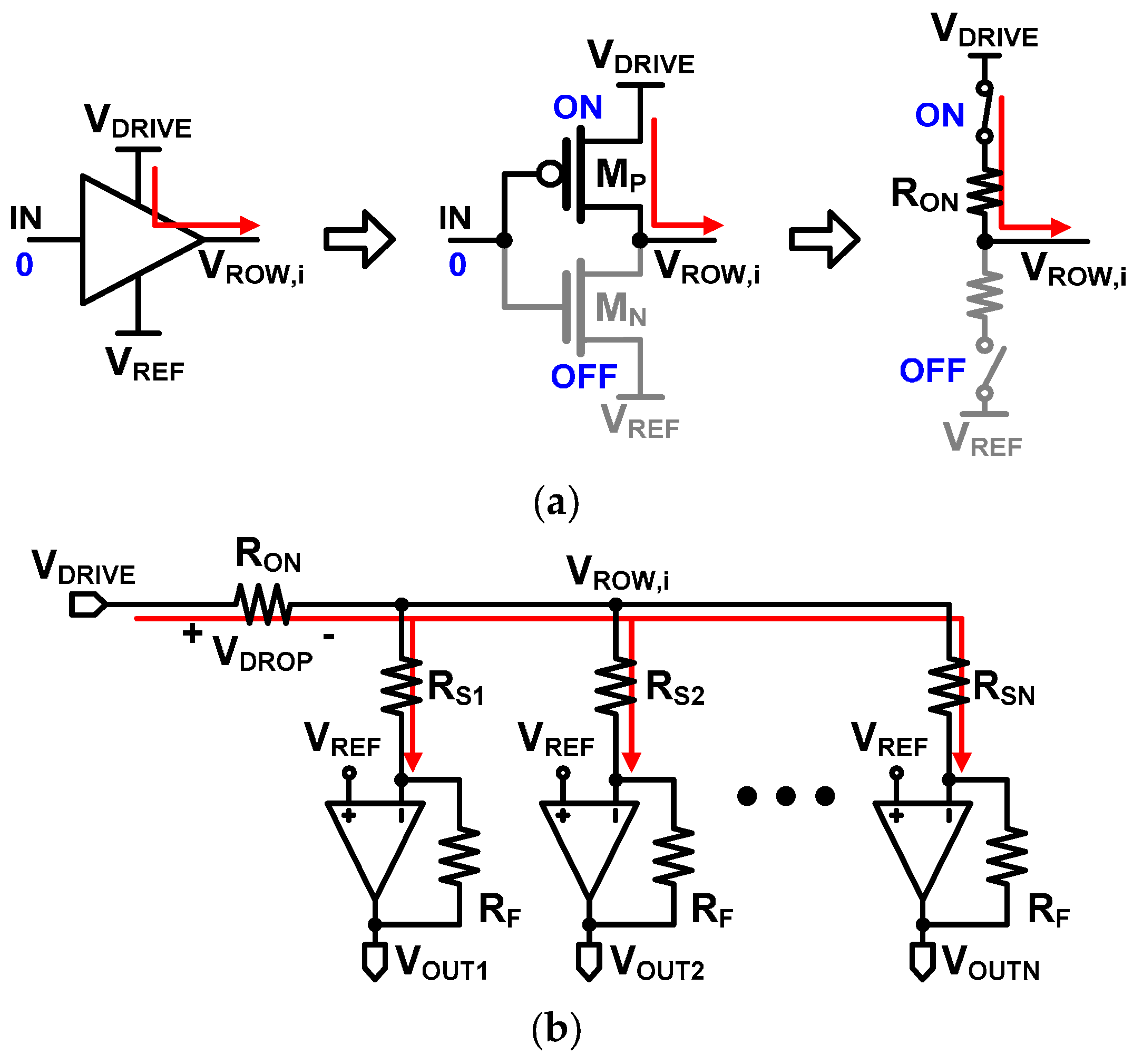
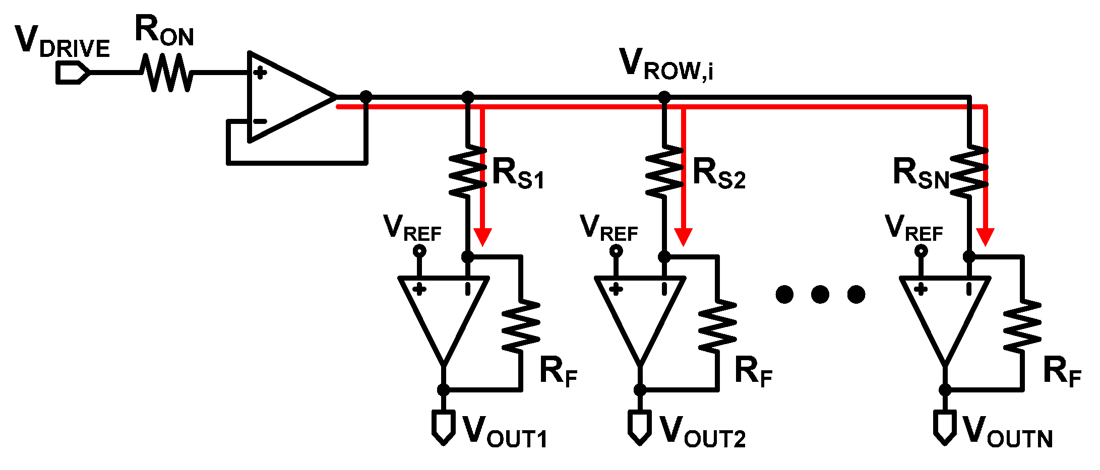
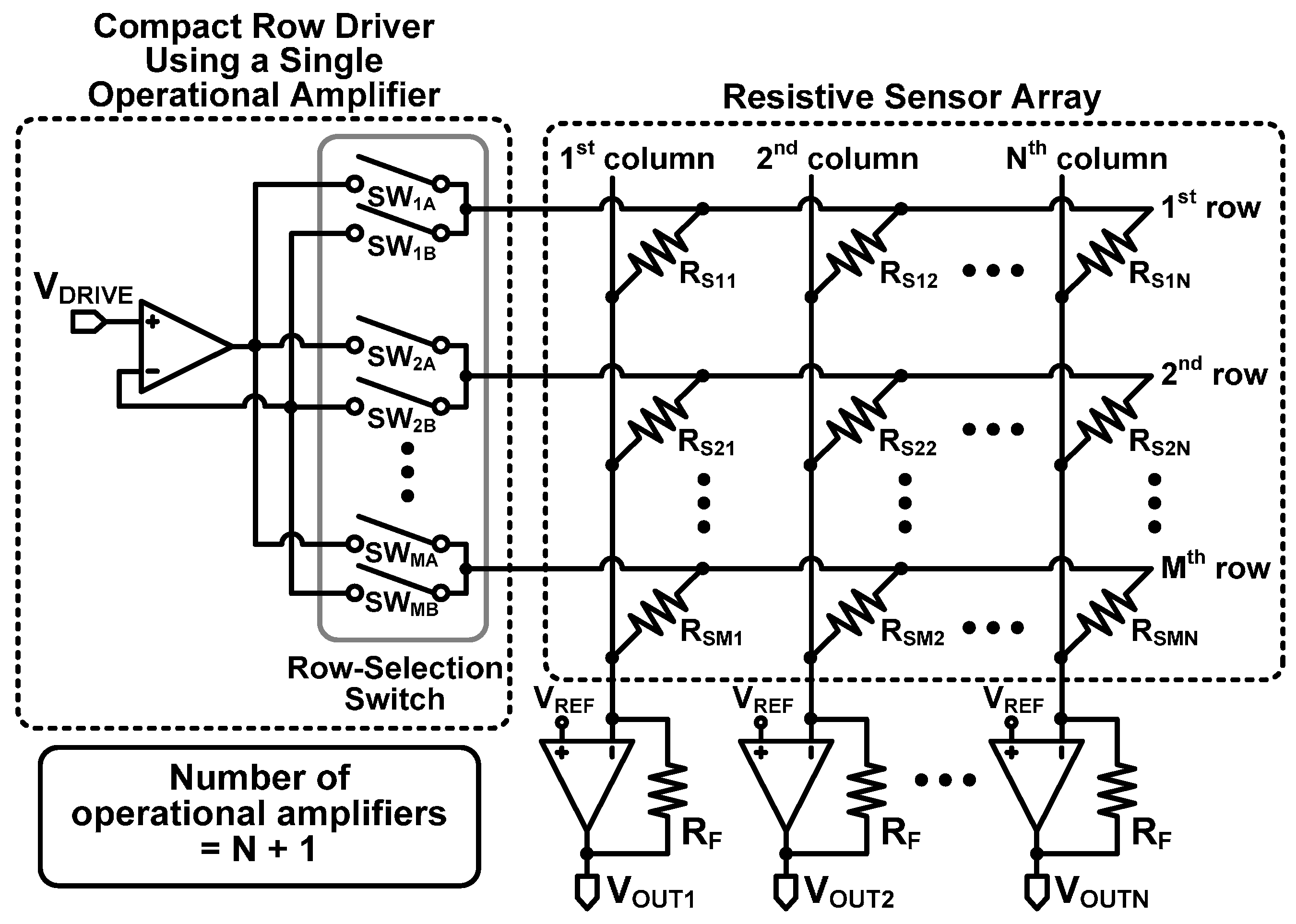
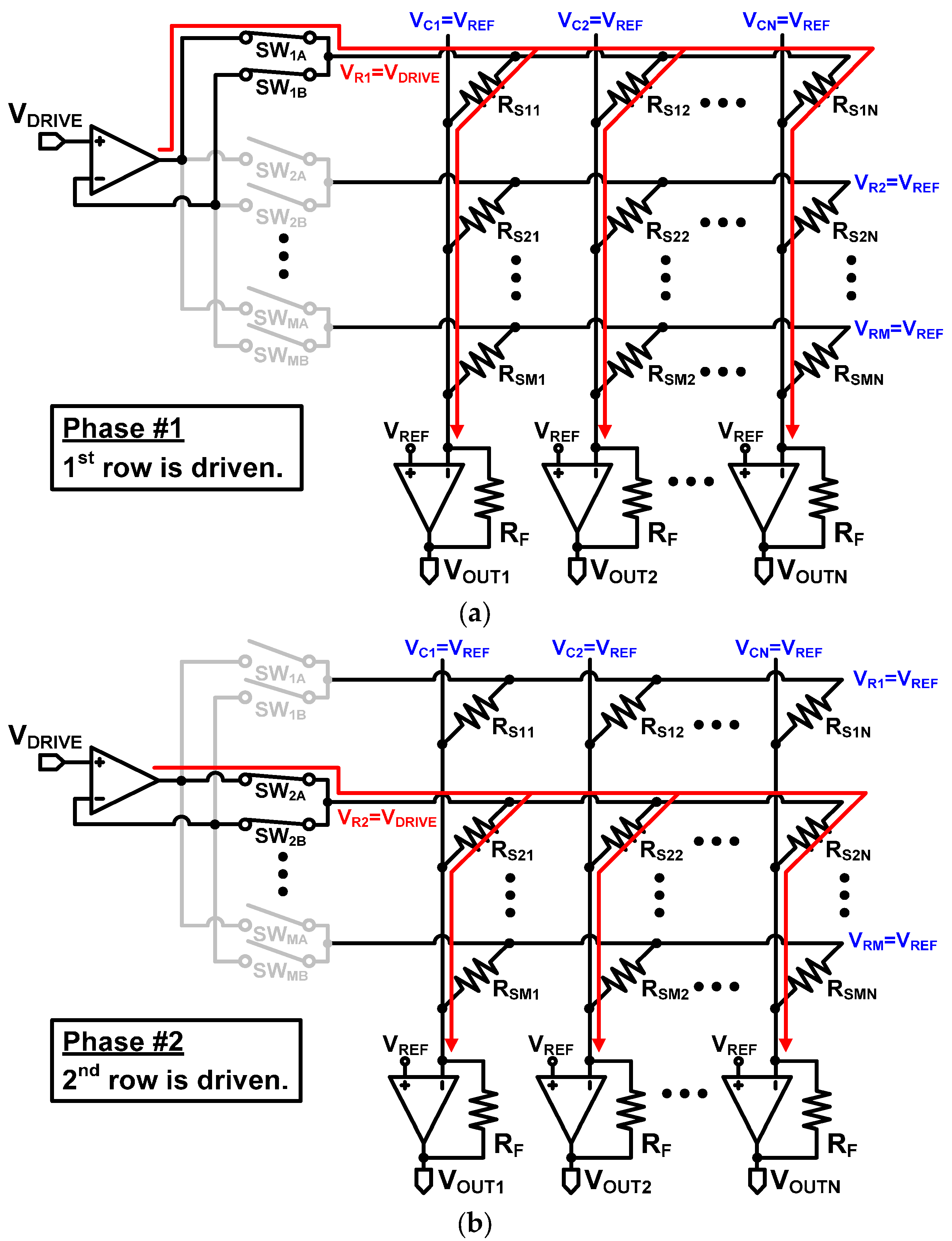
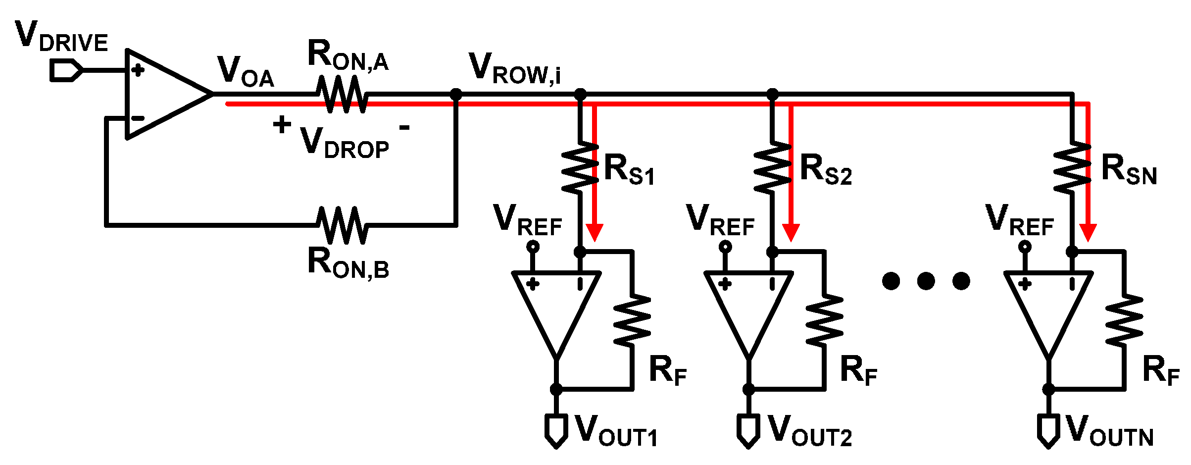
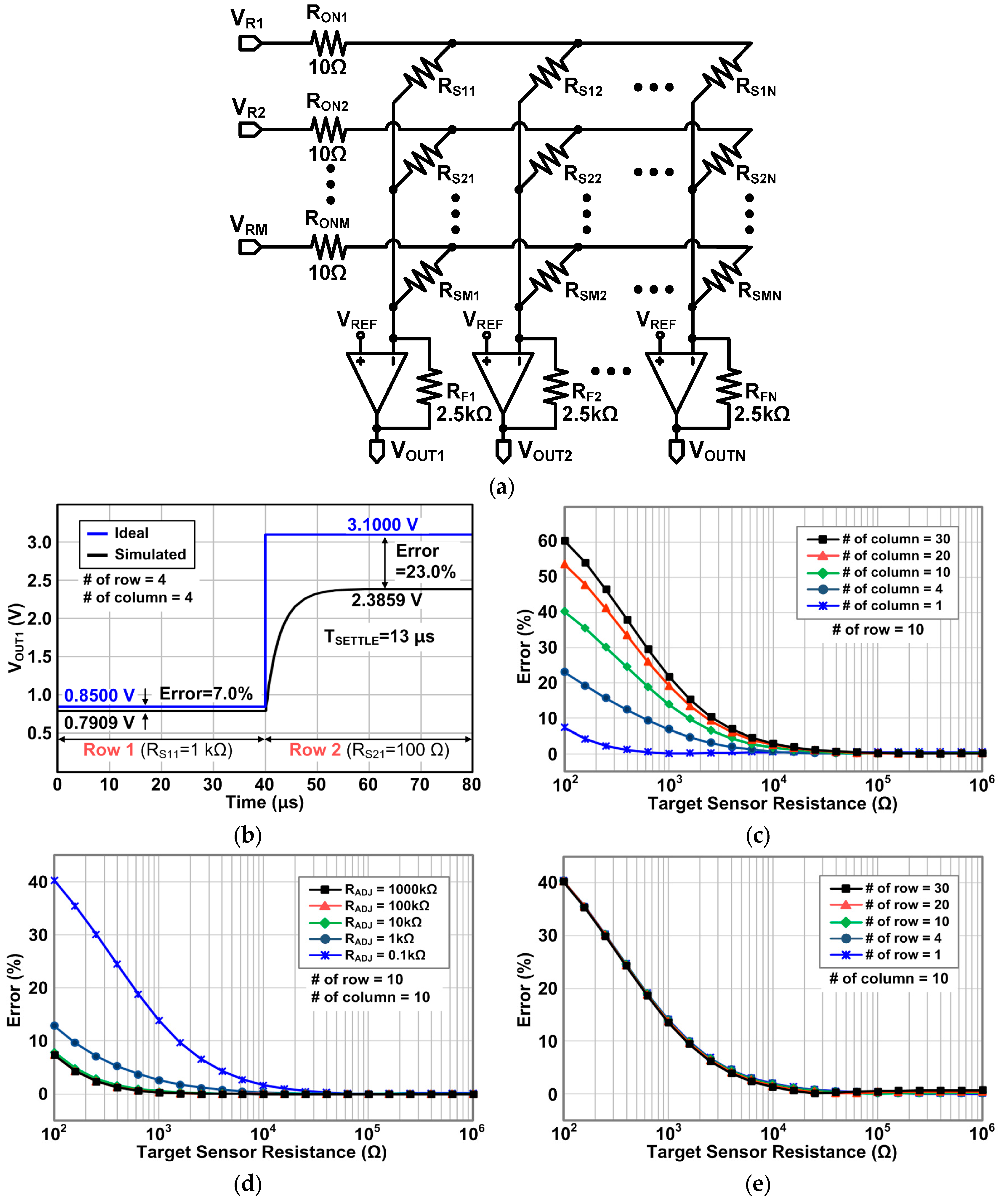
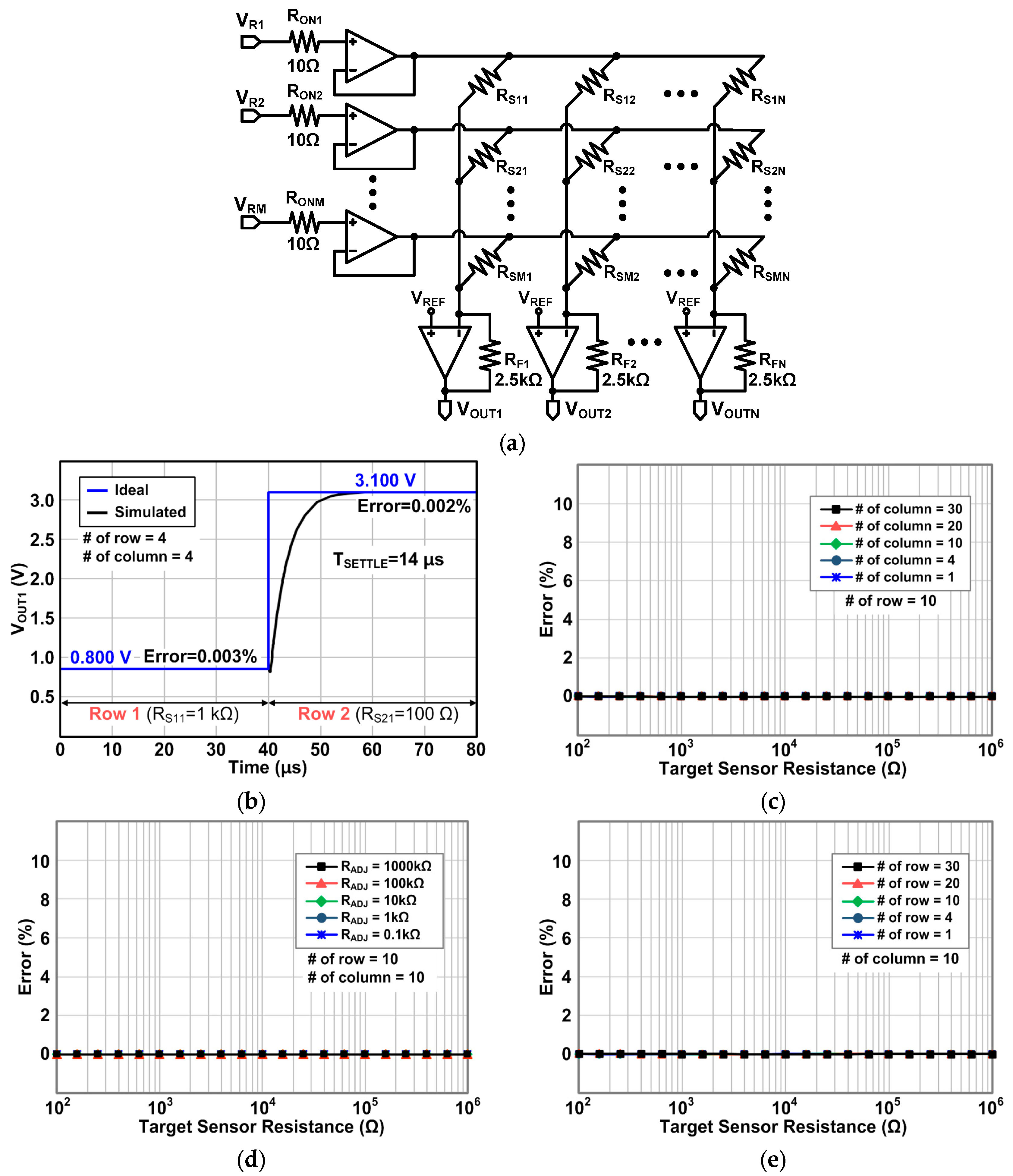
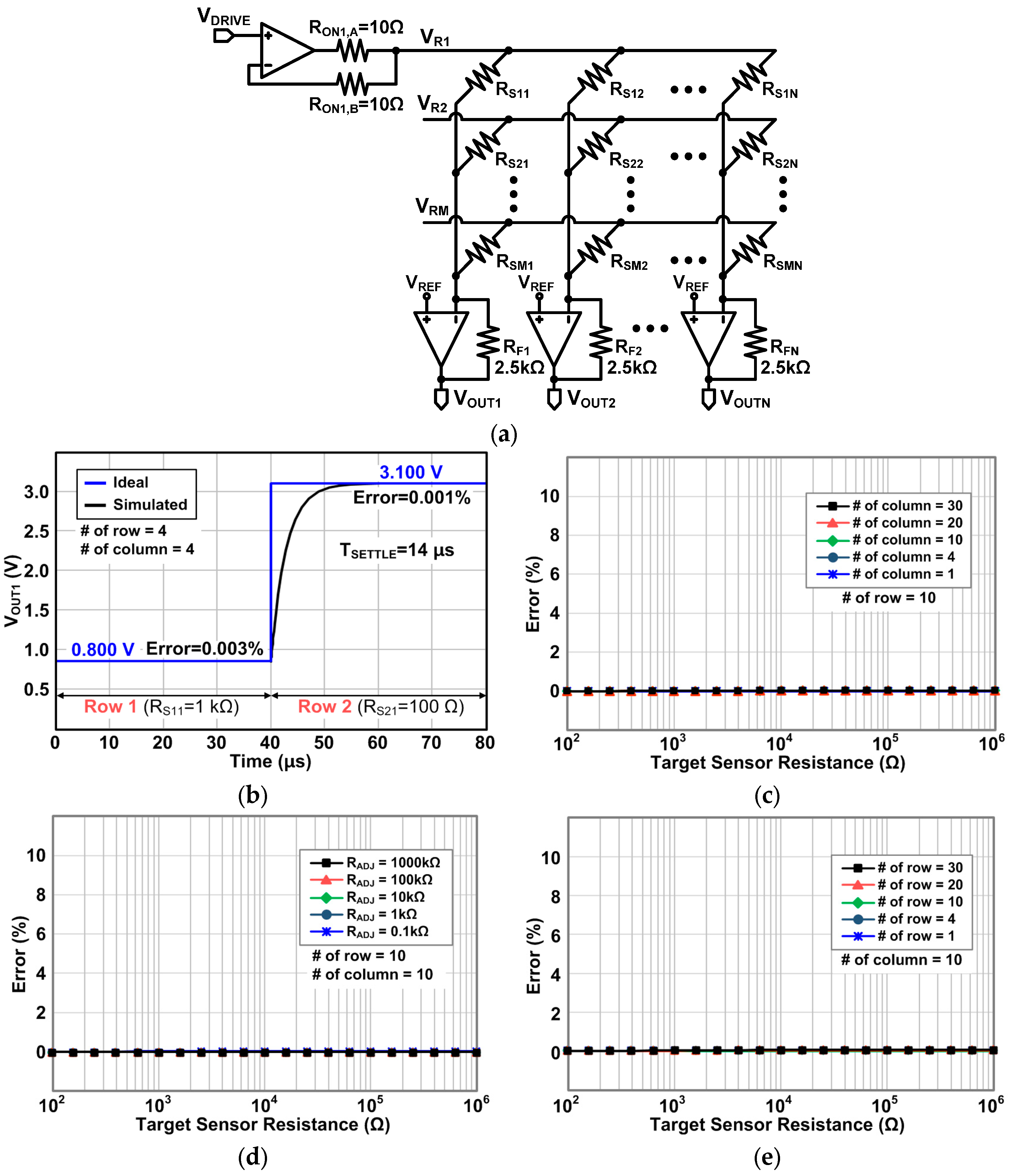
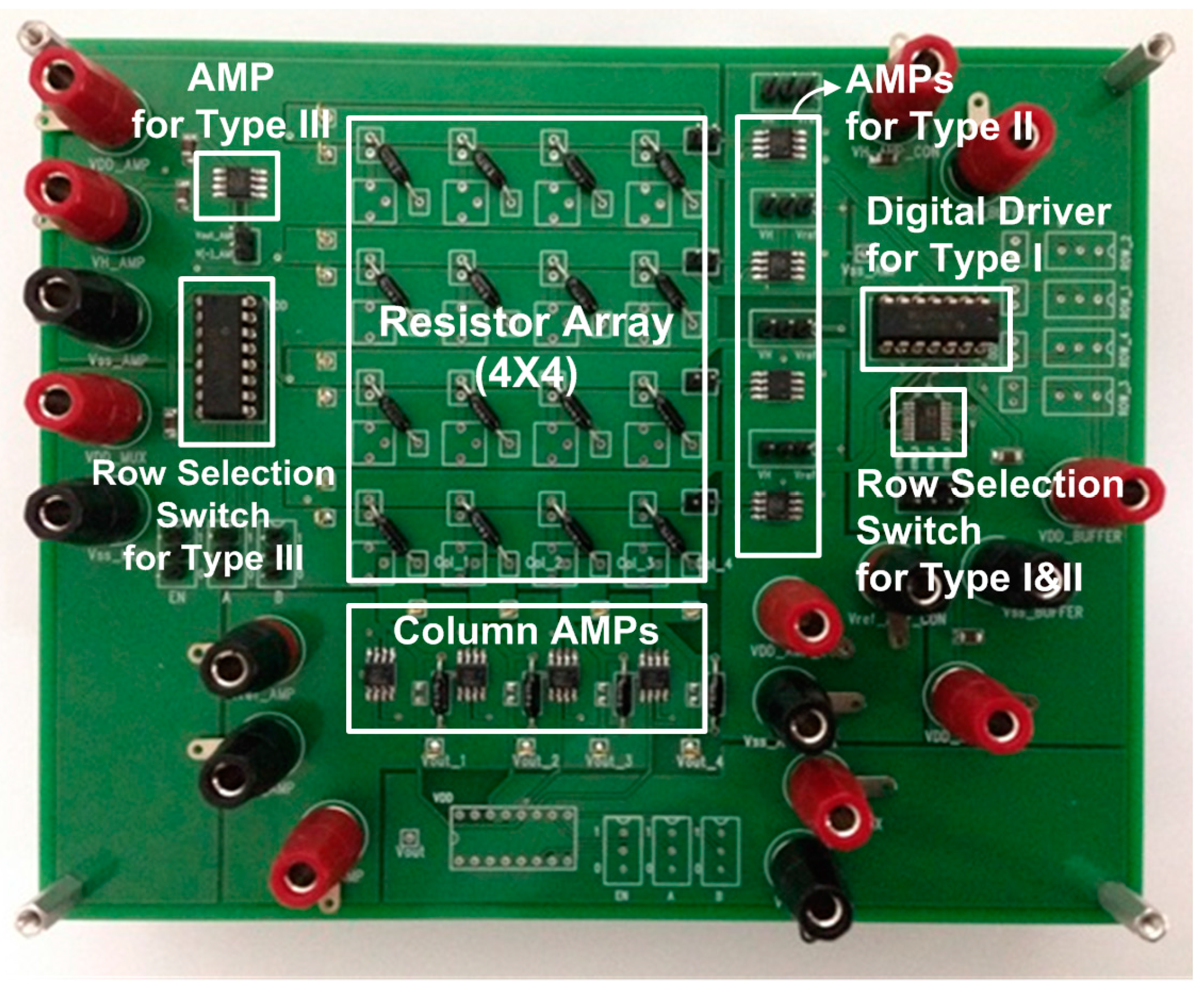
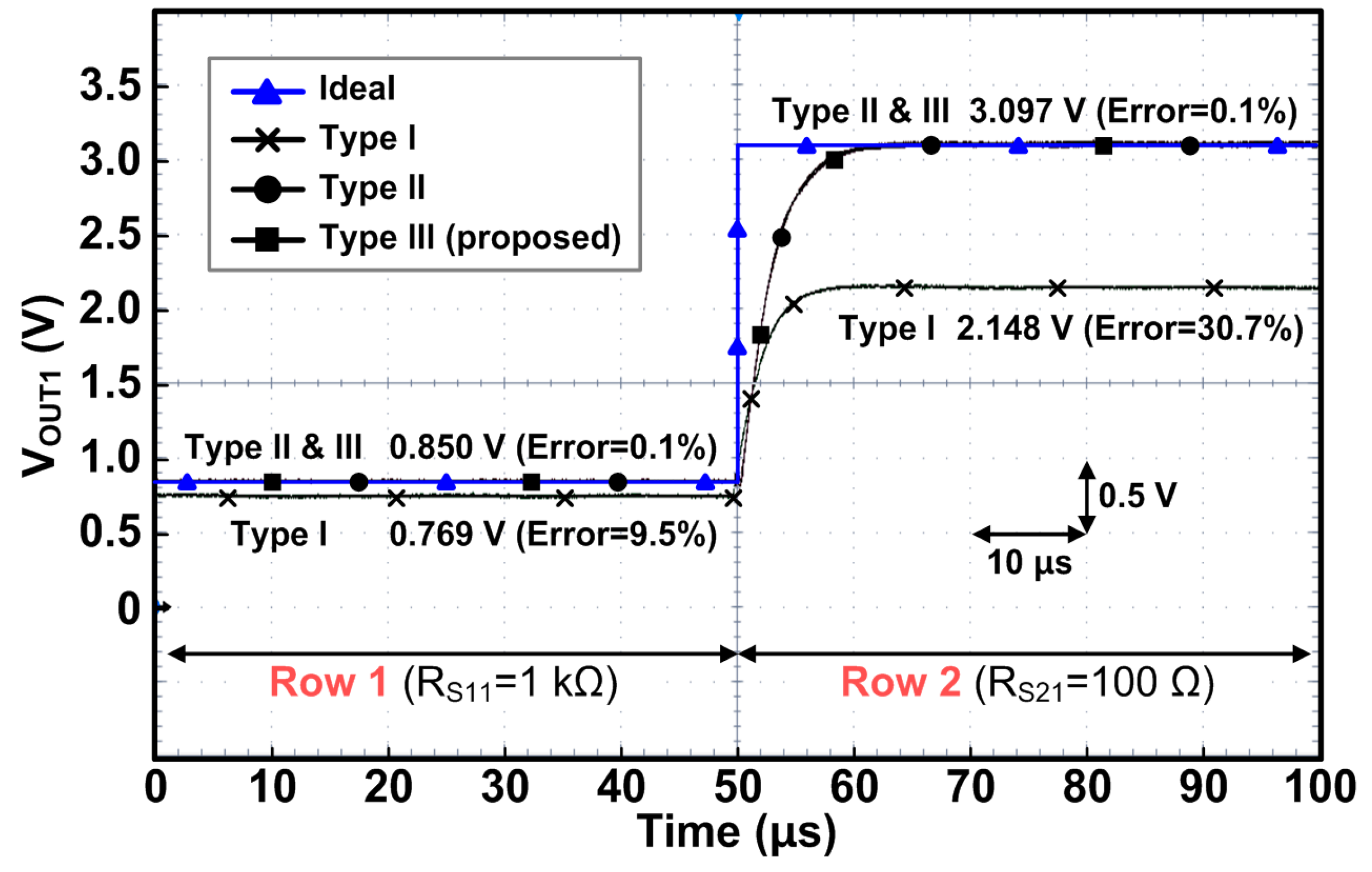
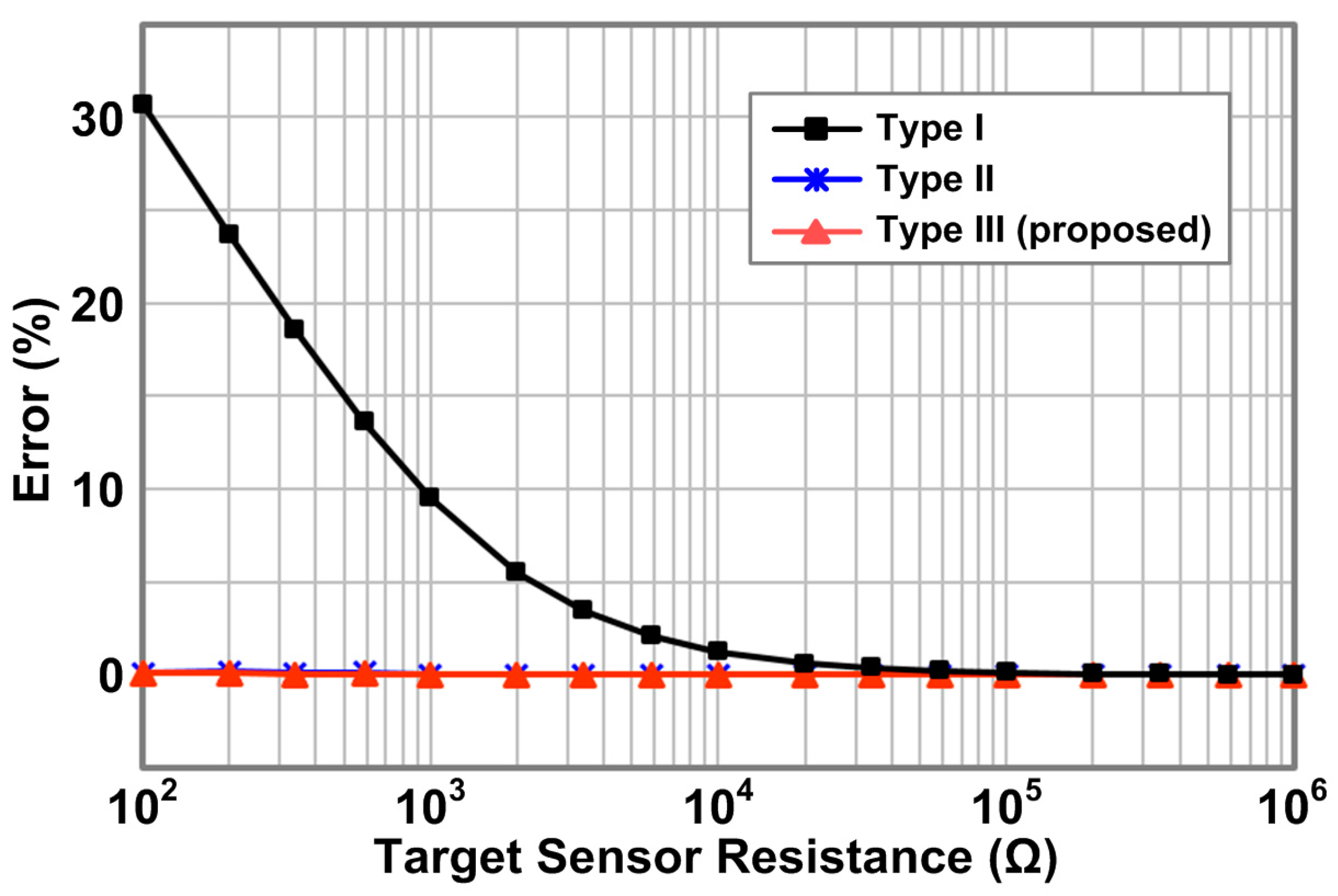
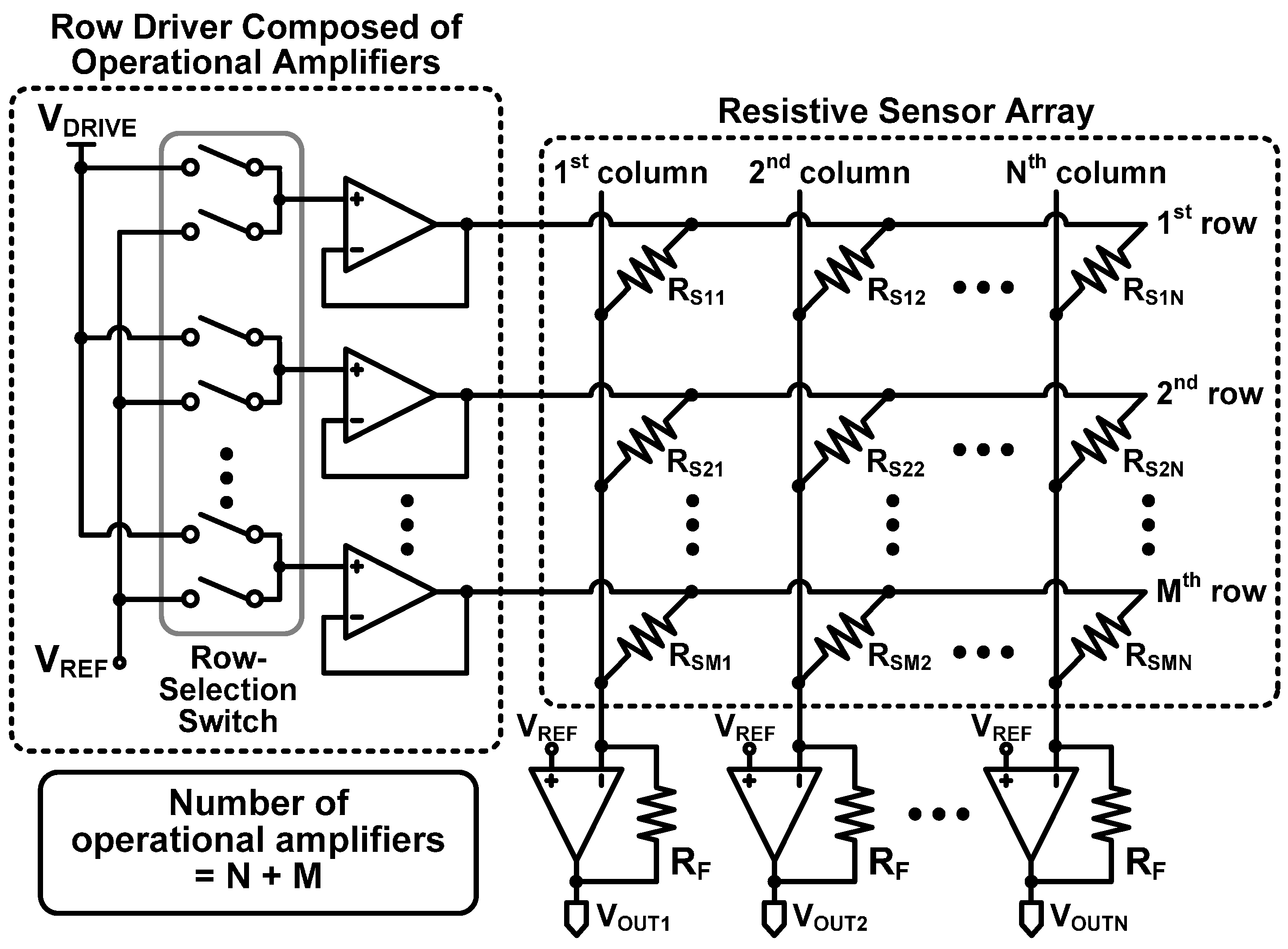
The zero-potential scanning circuit is widely used as read-out circuit for resistive sensor arrays because it removes a well known problem: crosstalk current. The zero-potential scanning circuit can be divided into two groups based on type of row drivers. One type is a row driver using digital buffers. It can be easily implemented because of its simple structure, but we found that it can cause a large read-out error which originates from on-resistance of the digital buffers used in the row driver. The other type is a row driver composed of operational amplifiers. It, very accurately, reads the sensor resistance, but it uses a large number of operational amplifiers to drive rows of the sensor array; therefore, it severely increases the power consumption, cost, and system complexity. To resolve the inaccuracy or high complexity problems founded in those previous circuits, we propose a new row driver which uses only one operational amplifier to drive all rows of a sensor array with high accuracy. The measurement results with the proposed circuit to drive a 4 × 4 resistor array show that the maximum error is only 0.1% which is remarkably reduced from 30.7% of the previous counterpart.
Keywords: resistive sensor; sensor array; crosstalk; read-out circuit; row driver resistive sensor; sensor array; crosstalk; read-out circuit; row driver