
Model-Based Angular Scan Error Correction of an Electrothermally-Actuated MEMS Mirror


Abstract
:
1. Introduction
2. Experimental Section
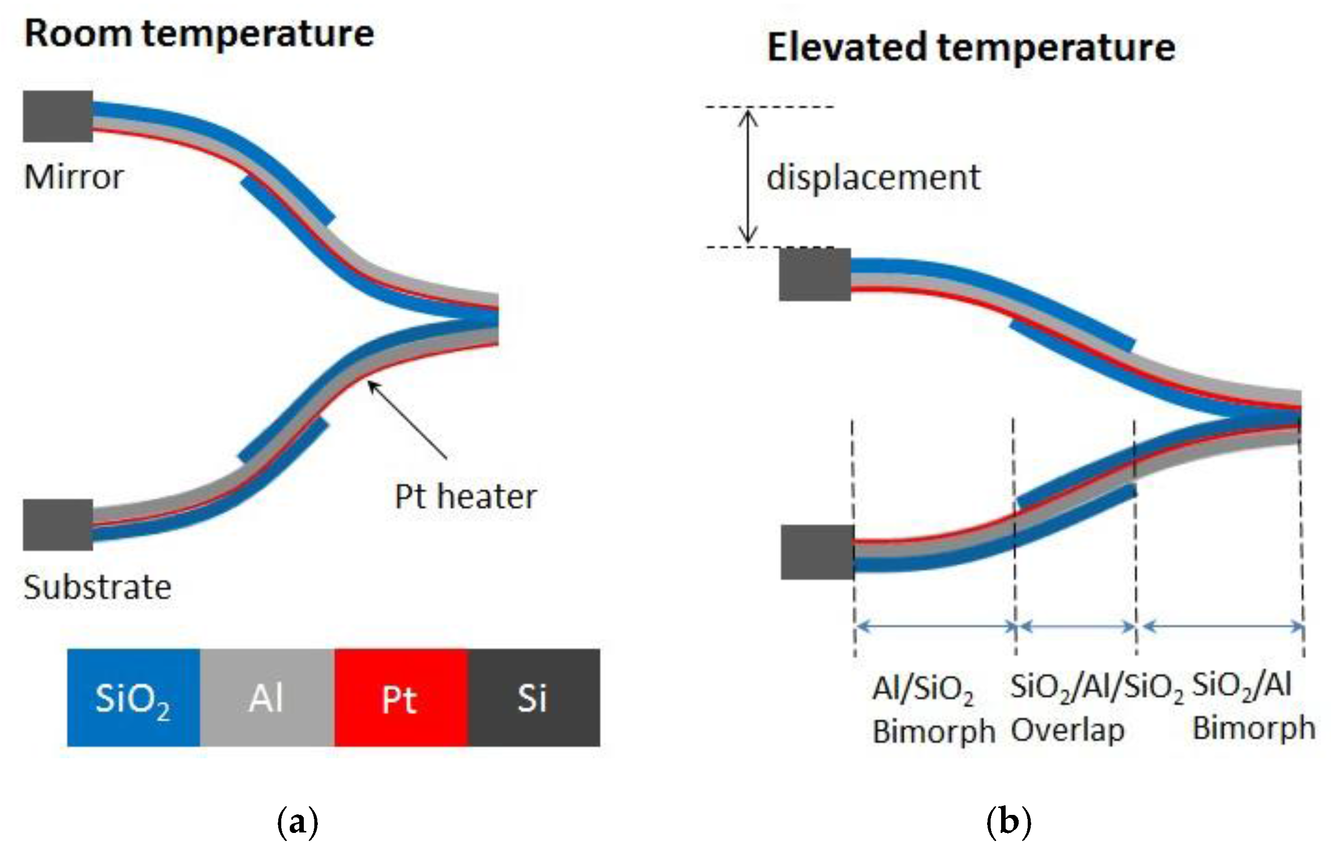
2.1. Design and Fabrication of Two-Axis ISC MEMS Mirror

2.2. Quasi-Static Tip-Tilt-Piston Characteristics of the ISC MEMS Mirror
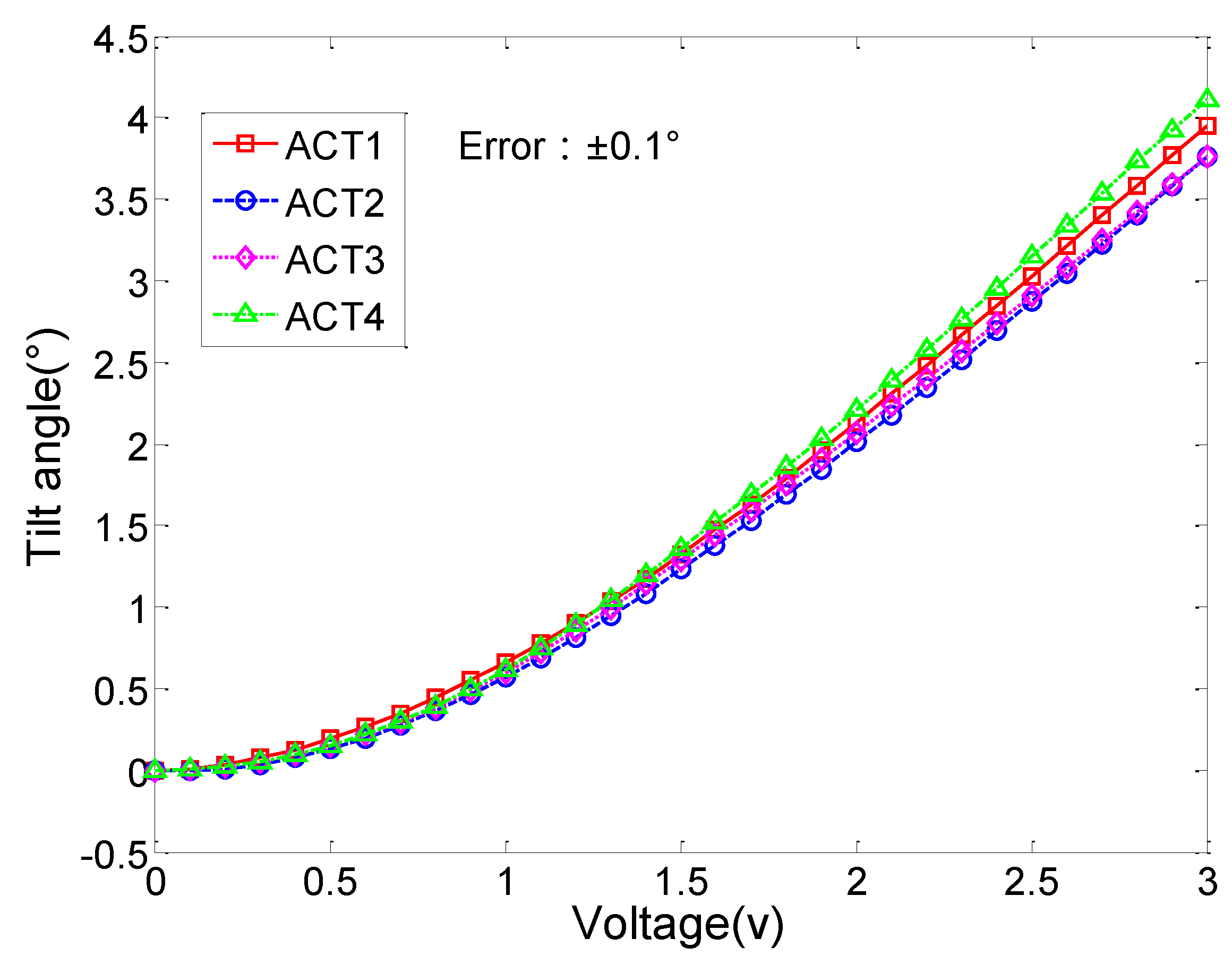
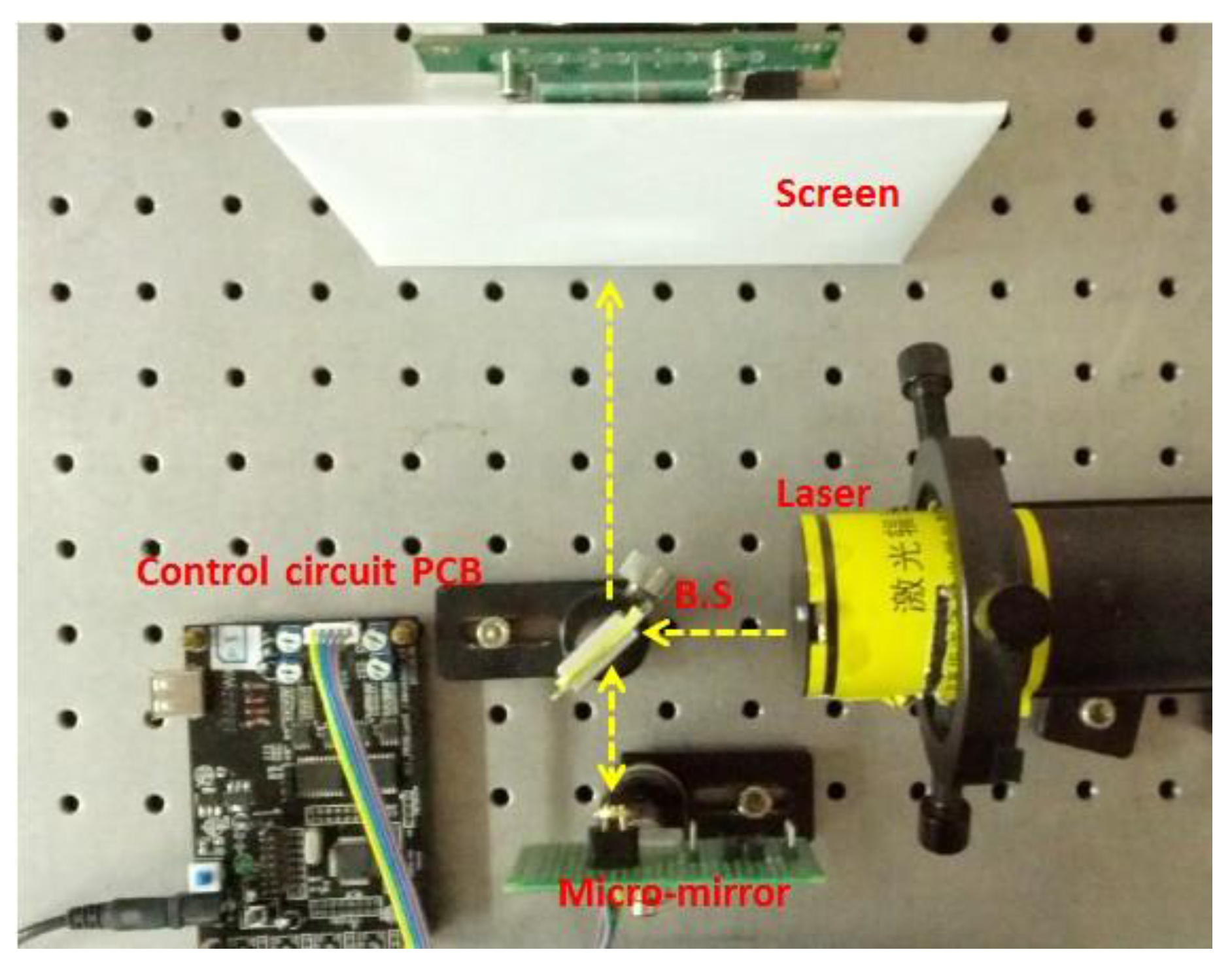
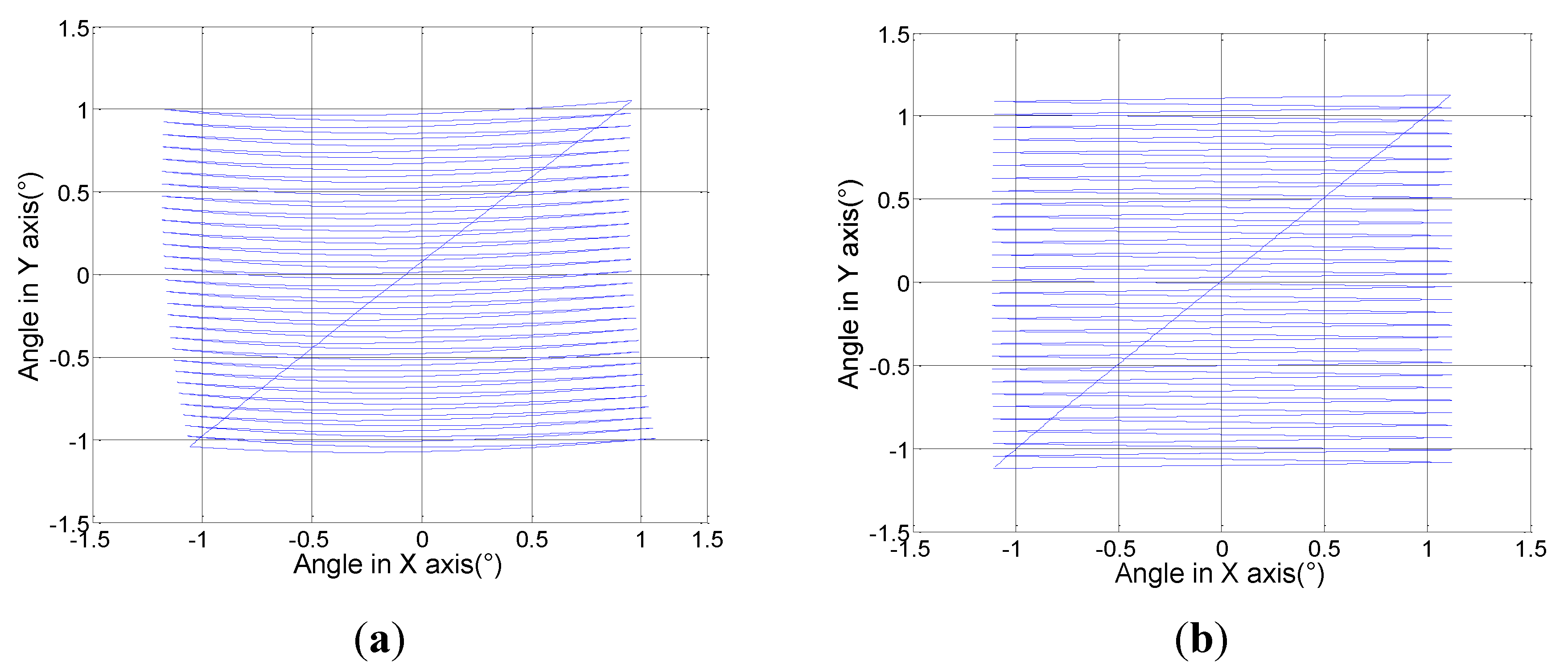
2.2.1. Angular Scan Measurements

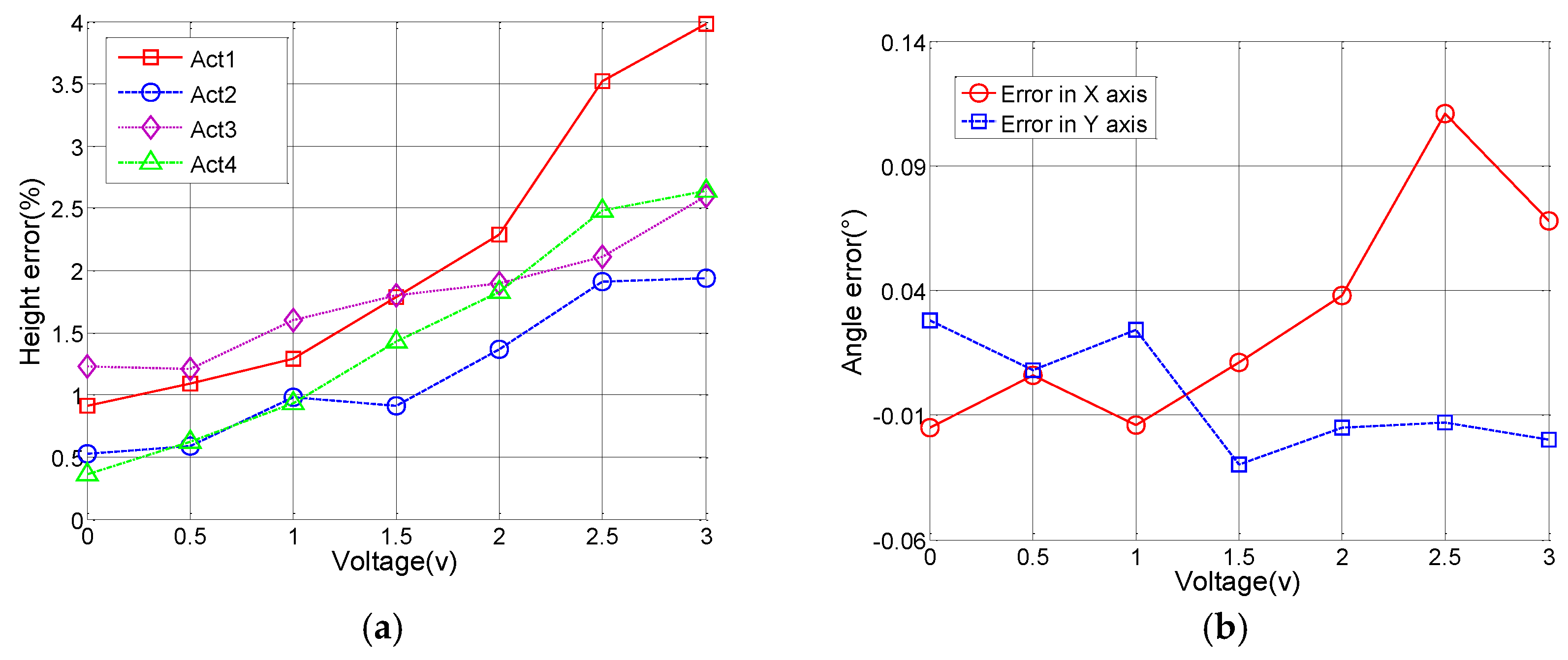
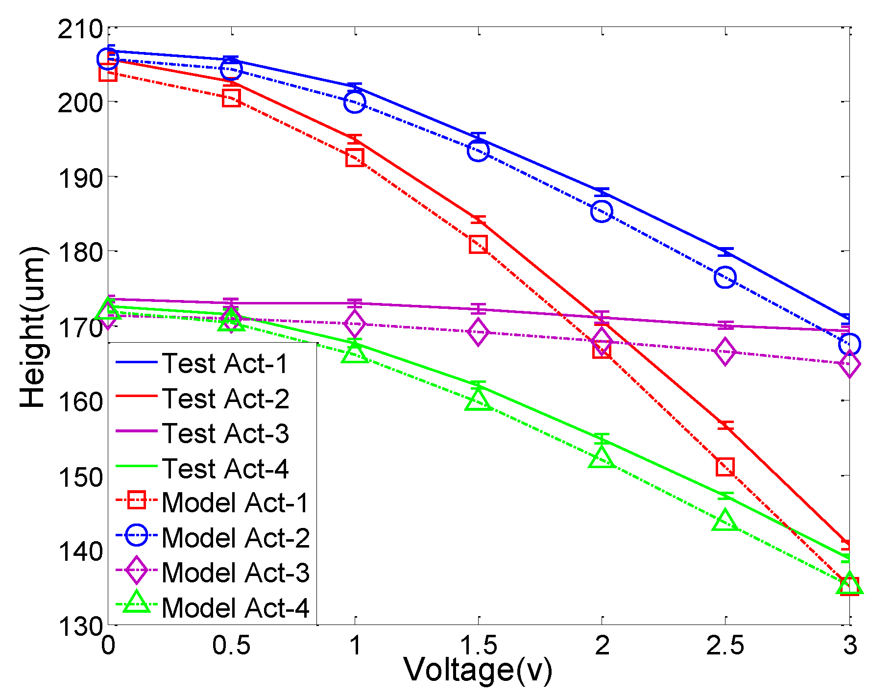
2.2.2. Measurement of the Heights of the Mirror Plate at the Four Actuator Anchor Points
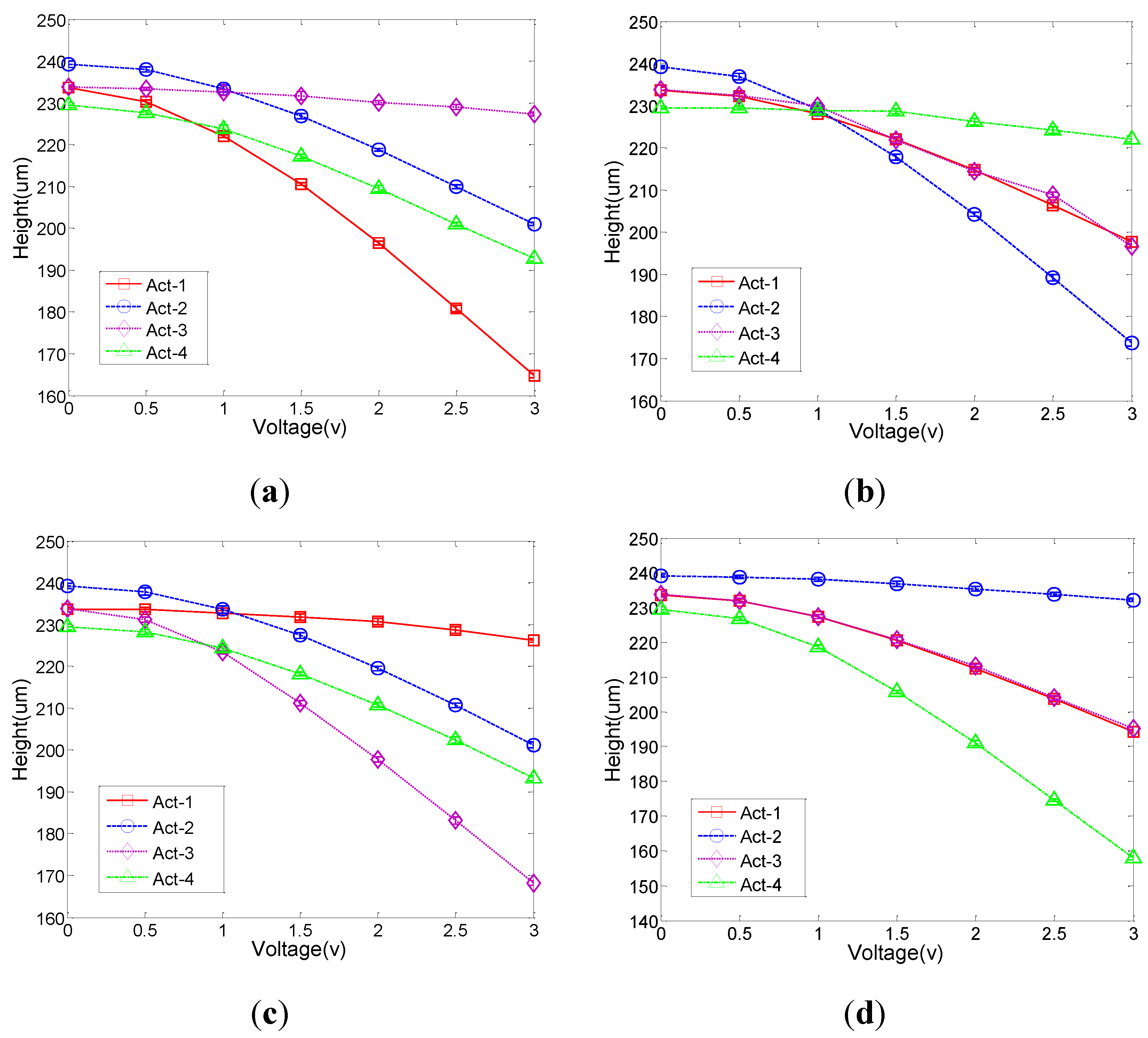
2.2.3. Identification of the Source of Actuation Errors
- (a)
- Actuator non-uniformity
- (b)
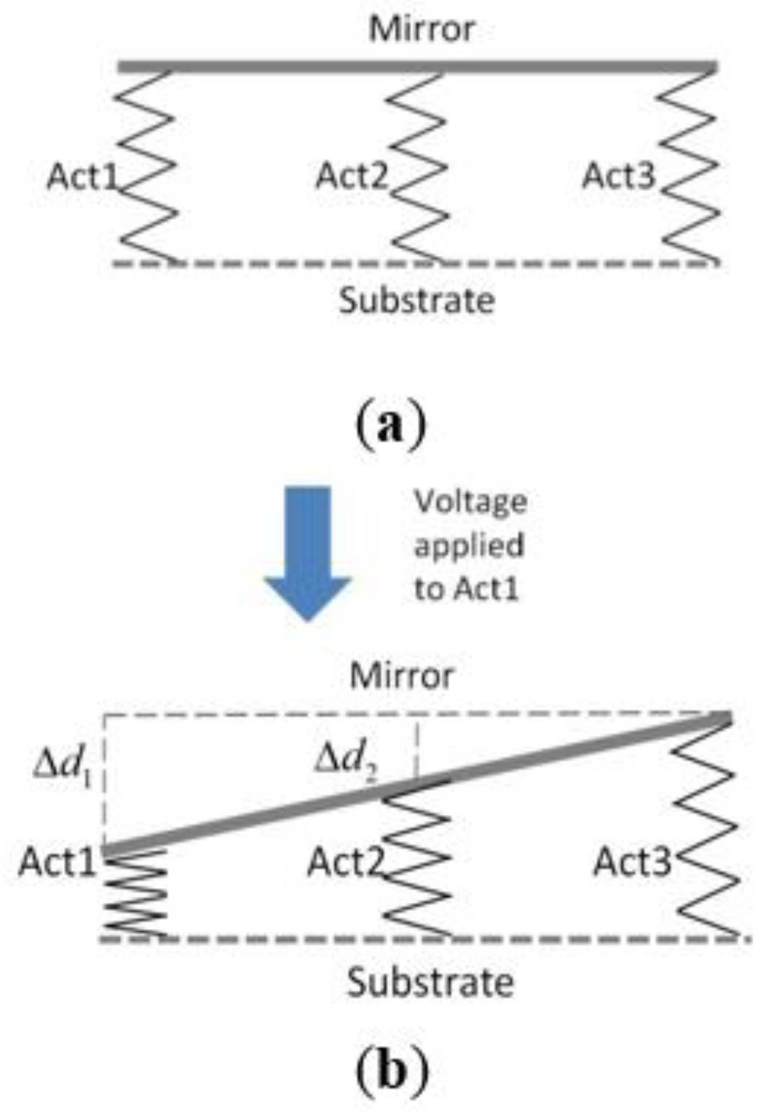
- Mechanical coupling

- (c)
- Initial heights of the four anchor points on the mirror plate
2.3. System Identification and Modeling
2.3.1. Establish of Mathematical Model for Predicting Static Output of Actuation

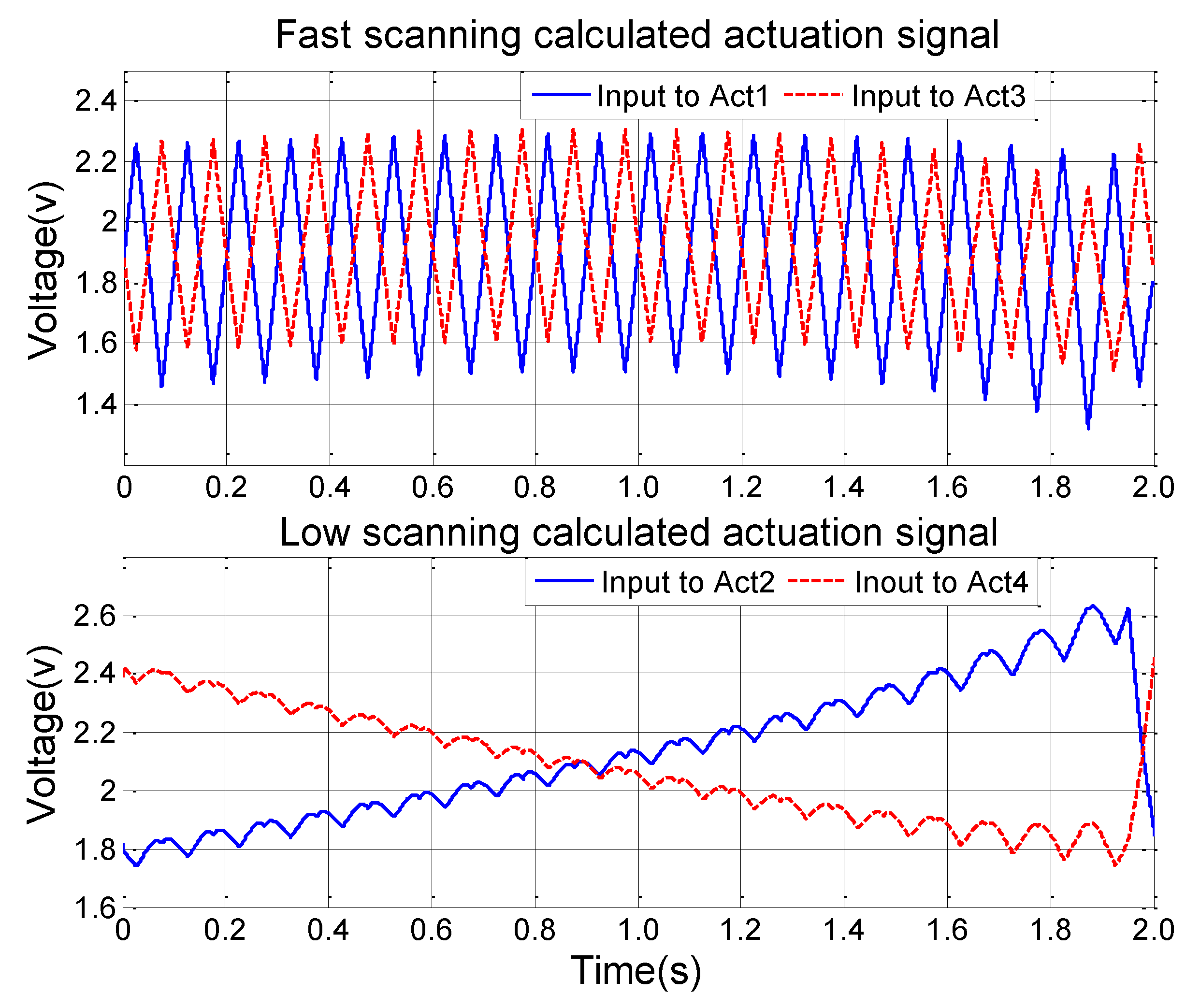
2.3.2. Construction of Compensated Control System Based on the Mathematical Model

2.4. Validation of the Static Model-Based Open-Loop Control System

3. Results and Discussion
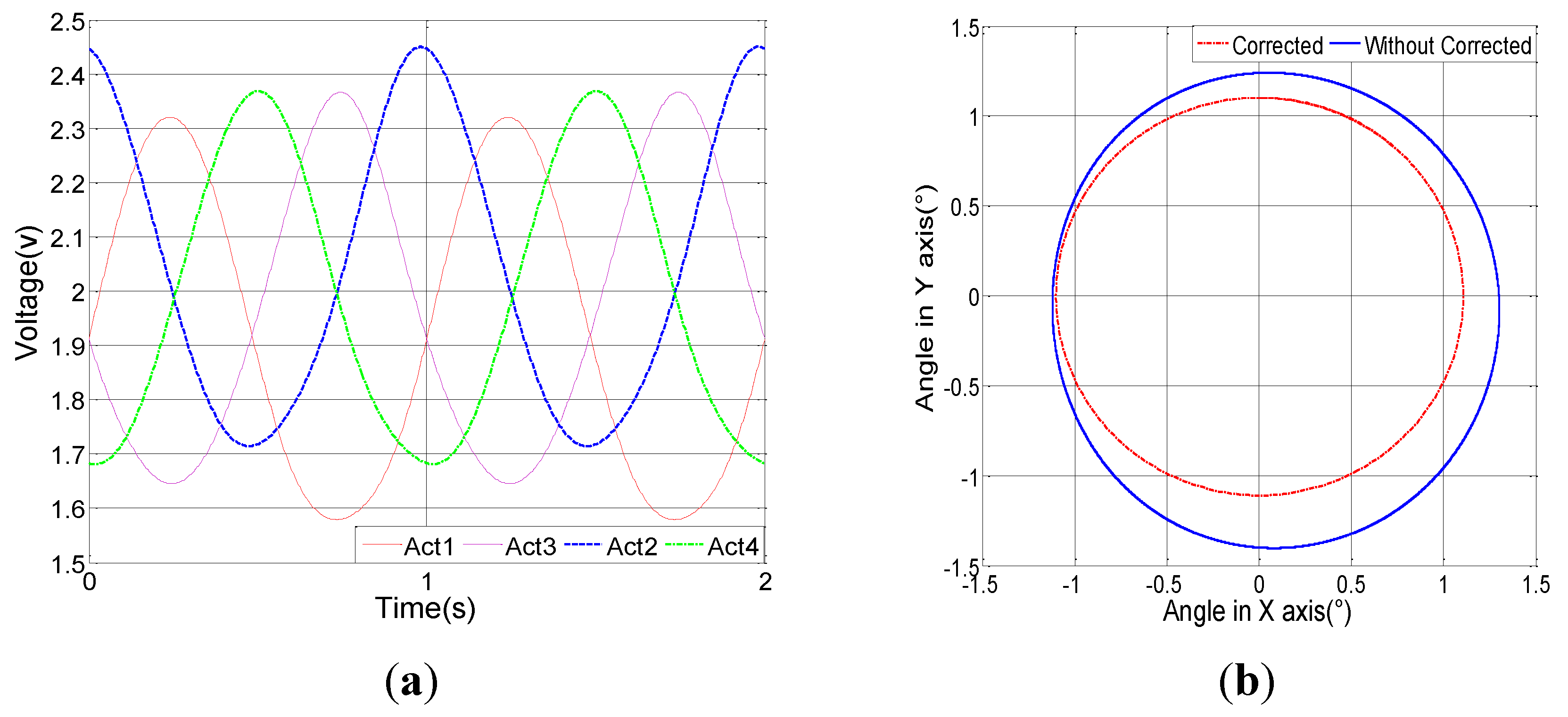
3.1. Output Signal Simulation of the Compensated Control System


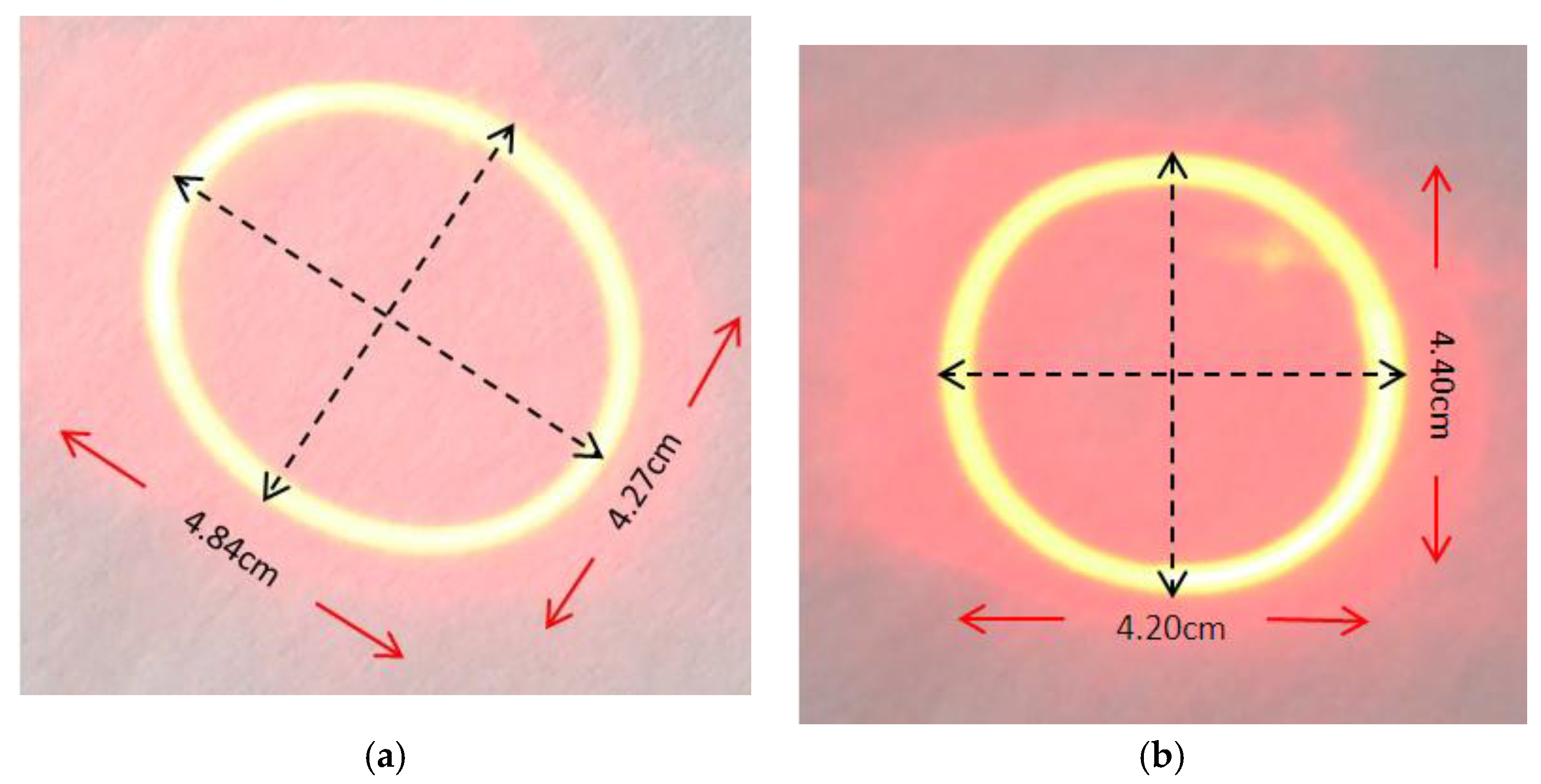
3.2. Improvement of the Laser Scanning Performance with the Compensated Control System

4. Conclusions
Acknowledgments
Author Contributions
Conflicts of Interest
References
- Wu, M.C. Micromachining for optical and optoelectronic systems. Proc. IEEE 1997, 85, 1833–1856. [Google Scholar] [CrossRef]
- Bernstein, J.; Taylor, W.P.; Brazzle, J.D.; Corcoran, C.J.; Kirkos, G.; Odhner, J.E.; Pareek, A; Waelti, M.; Zai, M. Electromagnetically Actuated Mirror Arrays for Use in 3-D Optical Switching Applications. J. Microelectromech. Syst. 2004, 13, 526–535. [Google Scholar] [CrossRef]
- Nakajima, M.; Kuwabara, K.; Sakata, T.; Usui, M.; Ishihara, T.; Kodate, J.; Hadama, K.; Nemoto, N.; Yamamoto, T.; Jin, Y. Low-voltage-actuated MEMS mirror array with high fill factor for photonic switch applications. In Proceedings of the 17th International Conference on Solid-State Sensors, Actuators and Microsystems (TRANSDUCERS & EUROSENSORS XXVII), 2013 Transducers & Eurosensors XXVII, Barcelona, Spain, 16–20 June 2013; pp. 1416–1419.
- Milanovic, V.; Matus, G.A.; McCormick, D.T. Gimbal-less monolithic silicon actuators for tip-tilt-piston micromirror applications. IEEE J. Sel. Top. Quantum Electron. 2004, 10, 462–471. [Google Scholar] [CrossRef]
- Samuelson, S.R.; Xie, H. A Large Piston Displacement MEMS Mirror with Electrothermal Ladder Actuator Arrays for Ultra-Low Tilt Applications. J. Microelectromech. Syst. 2014, 23, 39–49. [Google Scholar] [CrossRef]
- Wu, L.; Xie, H. A large vertical displacement electrothermal bimorph microactuator with very small lateral shift. Sens. Actuators A Phys. 2008, 145, 371–379. [Google Scholar] [CrossRef]
- Kim, S.J.; Cho, Y.H.; Nam, H.J.; Bu, J.U. Piezoelectrically pushed rotational micromirrors using detached PZT actuators for wide-angle optical switch applications. J. Micromech. Microeng. 2008, 18. [Google Scholar] [CrossRef]
- Yano, M.; Yamagishi, F.; Suda, T. Optical MEMS for photonic switching-compact and stable optical crossconnect switches for simple, fast, and flexible wavelength applications in recent photonic networks. IEEE J. Sel. Top. Quantum Electron. 2005, 11, 383–394. [Google Scholar] [CrossRef]
- Lee, C. A MEMS VOA using electrothermal actuators. J. Lightwave Tech. 2007, 25, 490–498. [Google Scholar] [CrossRef]
- Liu, L.; Pal, S.; Xie, H. MEMS mirrors based on a curved concentric electrothermal actuator. Sens. Actuators A Phys. 2012, 188, 349–358. [Google Scholar] [CrossRef]
- Wang, D.L.; Fu, L.; Wang, X.; Gong, Z.J.; Samuelson, S.; Duan, C.; Jia, H.Z.; Ma, J.S.; Xie, H.K. Endoscopic swept-source optical coherence tomography based on a two-axis microelectromechanical system mirror. J. Biomed. Opt. 2013, 18. [Google Scholar] [CrossRef] [PubMed]
- Jia, K.; Pal, S.; Xie, H.K. An Electrothermal Tip-Tilt-Piston Micro-mirror Based on Folded Dual S-Shaped Bimorphs. J. Microelectromech. Syst. 2009, 18, 1004–1015. [Google Scholar]
- Todd, S.T.; Xie, H.K. An Electrothermomechanical Lumped Element Model of an Electrothermal Bimorph Actuator. J. Microelectromech. Syst. 2008, 17, 213–225. [Google Scholar] [CrossRef]
- Samuelson, S.R.; Wu, L.; Sun, J.J.; Choe, S.W.; Sorg, B.S.; Xie, H.K. A 2.8-mmimaging Probe Based on A high-fill-factormems Mirror and Wire-bonding-free Packaging for Endoscopic Optical Coherence Tomography. J. Microelectromech. Syst. 2012, 21, 1291–1302. [Google Scholar] [CrossRef]
- Park, J.H.; Chung, T.; Jeon, J.A.; Kim, J.E.; Kim, M.; Kim, Y.K.; Na, G.; Park, I.H.; Yoo, B.W. Tracking control of electrostatically actuated micromirror with closed-loop feedback circuit. Electron. Lett. 2008, 44, 1295–1296. [Google Scholar] [CrossRef]
- Pannu, S.; Chang, C.; Muller, R.S.; Pisano, A.P. Closed-Loop Feedback-Control System for Improved Tracking in Magnetically Actuated Micromirrors. In Proceedings of the IEEE/LEOS International Conference on Optical MEMS, Kauai, HI, USA, 21–24 August 2000; pp. 107–108.
- Bhikkaji, B.; Ratnam, M.; Fleming, A.J.; Moheimani, S.O. High-Performance Control of Piezoelectric Tube Scanners. Trans. Contr. Syst. Tech. 2007, 15, 853–866. [Google Scholar] [CrossRef]
- Fujita, T.; Nagatani, Y.; Maenaka, K. MEMS Mirror Controlling System with Holed-PSD. In Proceedings of the 3rd International Conference on Emerging Trends in Engineering and Technology, Goa, India, 19–21 November 2010; pp. 446–449.
- Imam, H.T.; Adamson, R.; Brown, J.; Yuan, M. Two-Dimensional (2D) MicromirrorWith Enhanced Tilting Angle Using Active Control Methods. In Proceedings of the IEEE Photonics Society International Conference on Optical MEMS and Nanophotonics, Banff, AB, Canada, 6–9 August 2012; pp. 113–114.
- Chen, Q.; Zhang, H.; Zhang, X.Y.; Xu, D.C.; Xie, H.K. Repeatability Study of 2D MEMS Mirrors Based on S-Shaped Al/SiO2 Bimorphs. In Proceedings of the 8th Annual IEEE International Conference on Nano/Micro Engineered and Molecular Systems (NEMS2013), Suzhou, China, 7–10 April 2013; pp. 817–820.
- Ziegler, J.G.; Nichols, N.B. Optimumsettings for automatic controllers. Trans. ASME. 1942, 64, 759–768. [Google Scholar]
© 2015 by the authors; licensee MDPI, Basel, Switzerland. This article is an open access article distributed under the terms and conditions of the Creative Commons by Attribution (CC-BY) license (http://creativecommons.org/licenses/by/4.0/).
Share and Cite
Zhang, H.; Xu, D.; Zhang, X.; Chen, Q.; Xie, H.; Li, S. Model-Based Angular Scan Error Correction of an Electrothermally-Actuated MEMS Mirror. Sensors 2015, 15, 30991-31004. https://doi.org/10.3390/s151229840
Zhang H, Xu D, Zhang X, Chen Q, Xie H, Li S. Model-Based Angular Scan Error Correction of an Electrothermally-Actuated MEMS Mirror. Sensors. 2015; 15(12):30991-31004. https://doi.org/10.3390/s151229840
Chicago/Turabian StyleZhang, Hao, Dacheng Xu, Xiaoyang Zhang, Qiao Chen, Huikai Xie, and Suiqiong Li. 2015. "Model-Based Angular Scan Error Correction of an Electrothermally-Actuated MEMS Mirror" Sensors 15, no. 12: 30991-31004. https://doi.org/10.3390/s151229840
APA StyleZhang, H., Xu, D., Zhang, X., Chen, Q., Xie, H., & Li, S. (2015). Model-Based Angular Scan Error Correction of an Electrothermally-Actuated MEMS Mirror. Sensors, 15(12), 30991-31004. https://doi.org/10.3390/s151229840