Article

Conduction Mechanism and Magnetic Property of Ag-Doped LaFeO3 Nanofibers

Inner Mongolia Key Lab of Solid State Chemistry for Battery, Inner Mongolia Engineering Research Center of Lithium-Sulfur Battery Energy Storage, College of Chemistry and Materials Science, Inner Mongolia Minzu University, Tongliao 028000, China
*
Author to whom correspondence should be addressed.
These authors contributed equally to this work.
Molecules 2026, 31(7), 1174; https://doi.org/10.3390/molecules31071174
Submission received: 25 February 2026 / Revised: 27 March 2026 / Accepted: 31 March 2026 / Published: 2 April 2026
(This article belongs to the Special Issue Inorganic Chemistry in Asia, 2nd Edition)

Abstract

LaFeO3 nanofibers and Ag-doped LaFeO3 nanofibers were fabricated via an approach combining electrospinning with calcination. Their crystal structures, micro-morphologies, and chemical compositions were determined by X-ray diffraction, scanning electron microscopy, transmission electron microscopy, X-ray photoelectron spectroscopy, Raman spectroscopy, and Fourier-transform infrared spectroscopy. In addition, the conduction mechanisms and magnetic properties of the two samples were investigated using a semiconductor analyzer and a vibrating sample magnetometer. Rietveld refined X-ray diffraction analyses confirmed the orthorhombic structure. The two samples showed a nanofibrous structure. For Ag-doped LaFeO3, the conduction was dominated by the ohmic conduction mechanism in a low-resistance state, while it was governed by space-charge-limited current conduction in a high-resistance state. It also showed a high on/off ratio of 3.6 × 10³. The coercivity and remanence values of Ag-doped LaFeO3 were 200 Oe and 0.000404 emu g−1. This, thus, indicates the considerable application potential of Ag-doped LaFeO3 for resistive random-access memory devices and magnetoresistive random-access memory devices.

1. Introduction

ABO3-type perovskites have attracted tremendous research attention on account of their exceptional magnetic and electronic functionalities [1]. The perovskite crystal structure consists of a three-dimensional framework of corner-sharing BO6 octahedra, where A-site cations are situated in the cuboctahedral voids [2]. By varying the constituent elements within the ABO3 framework, these materials can be engineered for magnetic functional, electronic and energy applications [1,3]. Lanthanum ferrite (LaFeO3) is a typical lanthanum-based perovskite material and possesses stable electronic structure, efficient electron transport, p-type conductivity, low resistance and favorable photocatalytic activity. These merits have enabled the application of LaFeO3 in fields such as sensor technology, environmental remediation, and energy development [2,4,5,6]. In the ideal perovskite structure, the A-site La cation exhibits a coordination number of 12. For orthorhombically distorted LaFeO3, structural distortion reduces the coordination environment of La to approximately 8 [1,2]. The mixed ionic–electronic conductor that exhibits reversible redox behavior renders LaFeO3 a highly attractive candidate for resistive switching applications [7,8]. LaFeO3 is a representative G-type antiferromagnetic material. The super-exchange and Dzyaloshinsky–Moriya interactions between Fe ions induce the formation of a canted antiferromagnetic order in LaFeO3 [1]. The conditions for ferroelectricity and magnetism are mutually exclusive, apart from a small number of multiferroic materials such as BiFeO3 and LaFeO3 [8]. It is reported that the surface termination of perovskite oxides is typically dominated by inert AO planes, as opposed to the reactive B-site centers, which leads to the passivation of surface reactivity and related functionalities. By engineering A-site metal ion vacancies within the perovskite lattice, the oxidation state of B-site cations and the density of oxygen vacancies can be efficiently tuned. Additionally, this defect engineering strategy can induce lattice distortion in the perovskite, thereby facilitating the generation of localized regions with high electron density [9]. A-site lattice imperfections and the induced oxygen vacancies synergistically enhance surface reaction activity, and furnish optimal nucleation loci for the deposition of Ag and analogous metal nanoparticles, facilitating the creation of strong metal–support interactions and effective interfacial Schottky junctions. Consequently, A-site defect engineering in LaFeO3 enables high-performance photocatalyst nanocomposites for CO2 reduction [9]. Noble metal doping is an effective approach to enhance the practical application performance of LaFeO3 [6]. Silver ions can intercalate into the crystal lattice of LaFeO3, introducing reactive sites and enhancing the efficiency of charge carrier separation and utilization [6,9]. Ag-doped LaFeO3 shows great potential application in ethanol detection, photocatalysts for CO2 conversion to CH3OH, and gas sensors [2,6,9,10]. LaFeO3 and its doped variants can be prepared using several techniques, including electrospinning, hydrothermal synthesis, solid-state reaction, and combustion synthesis [11,12,13,14]. Electrospinning is a facile method to controllably prepare continuous one-dimensional nanofibers (NFs) with a large aspect ratio, high specific surface area, and uniform porous structure [15]. These features are highly favorable for charge transport and interface-related properties in resistive switching and magnetic applications. This method allows homogeneous doping of Ag ions in the LaFeO3 lattice during the nanofiber-forming process, ensuring good compositional uniformity and structural stability.
This study aims to synthesize one-dimensional Ag-doped LaFeO3 NFs via electrospinning; systematically investigate the structural evolution, conduction behavior, and magnetic properties; and reveal the influence of Ag doping on the microstructure and multifunctional performance of LaFeO3-based NFs. Via electrospinning combined with calcination at high temperature, pure and Ag-doped LaFeO3 NFs were successfully synthesized. The crystalline structure, microstructural features, and chemical composition of the fabricated samples were systematically characterized. This study confirms that the Ag-doped LaFeO3 NFs show significant potential for resistive random-access memory and magnetoresistive random-access memory.

2. Results and Discussion

2.1. Structural Investigation

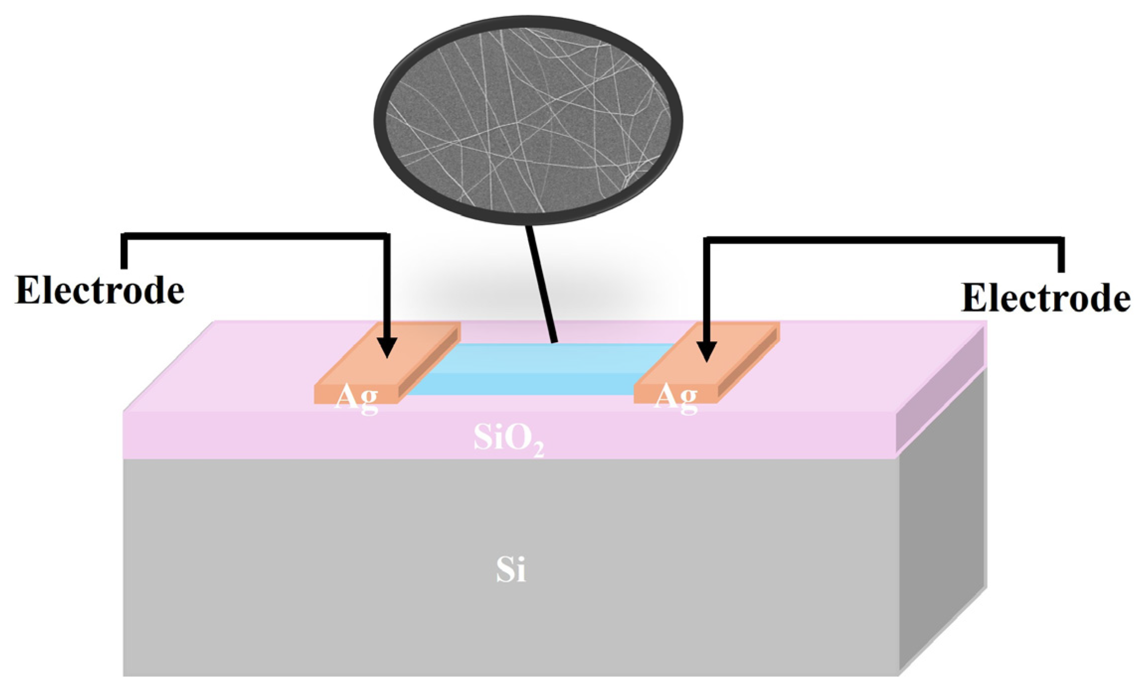
Figure 1 is the schematic illustration of the fabricated devices.
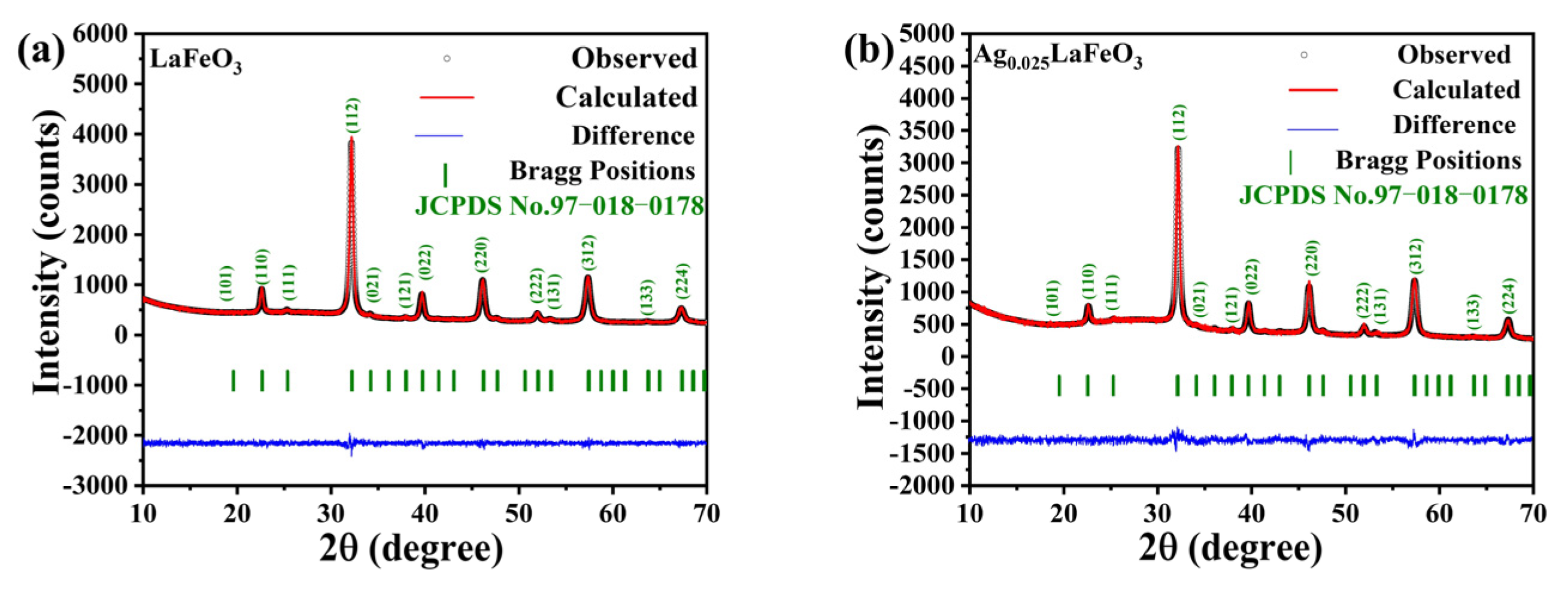
Rietveld refinement of the XRD data was used to determine the lattice parameters of LaFeO3 and Ag0.025LaFeO3. As shown in Figure 2, XRD patterns exhibited sharp and narrow peaks with high intensity, which was indicative of good crystallinity in the synthesized LaFeO3 and Ag0.025LaFeO3. According to JCPDS No. 97-018-0178, it confirmed the orthorhombic crystal structure with the Pbnm(62) space group, and no secondary or impurity phases were observed. XRD results proved the complete dissolution of Ag+ into the LaFeO3 lattice without impurity formation. The ionic-radius values of Ag+, La3+ and Fe3+ are 0.115 nm, 0.103 nm and 0064 nm, respectively. Given the similar ionic radii of Ag+ and La3+, Ag+ ions can easily occupy the La3+ positions in the LaFeO3 perovskite structure [6]. The larger ionic radius of Ag+ than that of Fe3+ may lead to an increase in the Fe-O bond length, thereby causing the lattice to expand along the b-axis. Therefore, the introduction of Ag ions in LaFeO3 led to slight lattice expansion. Furthermore, the goodness-of-fit (GOF) values obtained from the Rietveld refinement for LaFeO3 and Ag0.025LaFeO3 were less than 2, which confirmed the high accuracy of the refinement results. The lattice parameters of LaFeO3 and Ag0.025LaFeO3 were summarized in Table 1.

2.2. Morphological Analyses

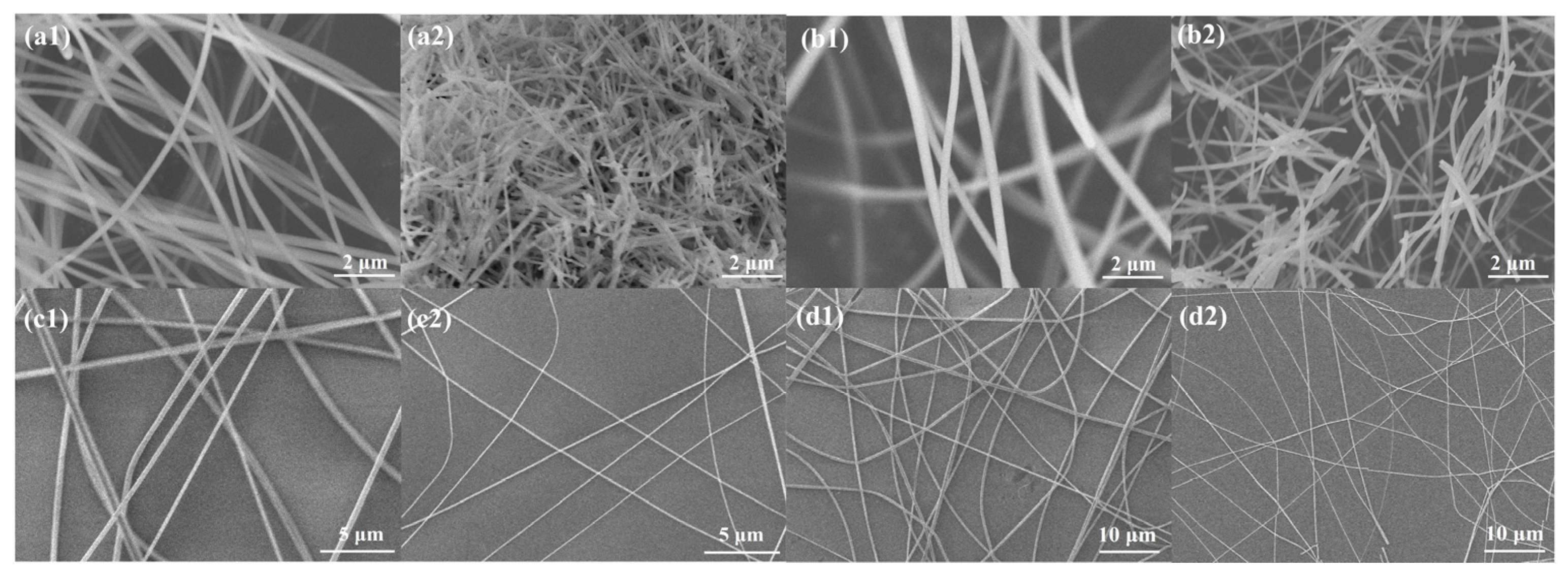
To characterize the morphological and structural features, the LaFeO3 and Ag0.025LaFeO3 samples were systematically investigated via SEM measurement. As shown in Figure 3(a1,b1), La(NO3)3-FeAc2/PVP and La(NO3)3-FeAc2-AgAc/PVP precursors exhibited a smooth nanofibrous morphology, and the electrospun precursor NFs were intertwined with each other. The NFs were relatively uniformly distributed without obvious agglomeration or clumping, featuring a narrow diameter distribution and regular morphology, with diameters ranging from approximately 240 to 380 nm. The surfaces of the precursor NFs were smooth and free of pores or protrusions, which was attributed to the rapid volatilization of DMF during the electrospinning process and the uniform solidification and formation of PVP and metal salt precursors. According to Figure 3(a2,b2), high-temperature calcination induced a profound morphological evolution of the precursor NFs, featuring shortened length, diminished diameter size, and distinctly enhanced surface roughness. This phenomenon was mainly attributed to the decomposition of PVP and the decomposition and crystallization shrinkage of La(NO3)3, FeAc2, and AgAc during the calcination process. Additionally, the NFs retained a narrow diameter distribution after calcination. Figure 3(c1,d1) presented La(NO3)3-FeAc2/PVP and La(NO3)3-FeAc2-AgAc/PVP precursors on SiO2/Si substrate. These precursor NFs exhibited a continuous and interconnected network structure. According to Figure 3(c2,d2), these network structures were still maintained even after high-temperature calcination treatment, and most nanofibers retained a continuous morphology.
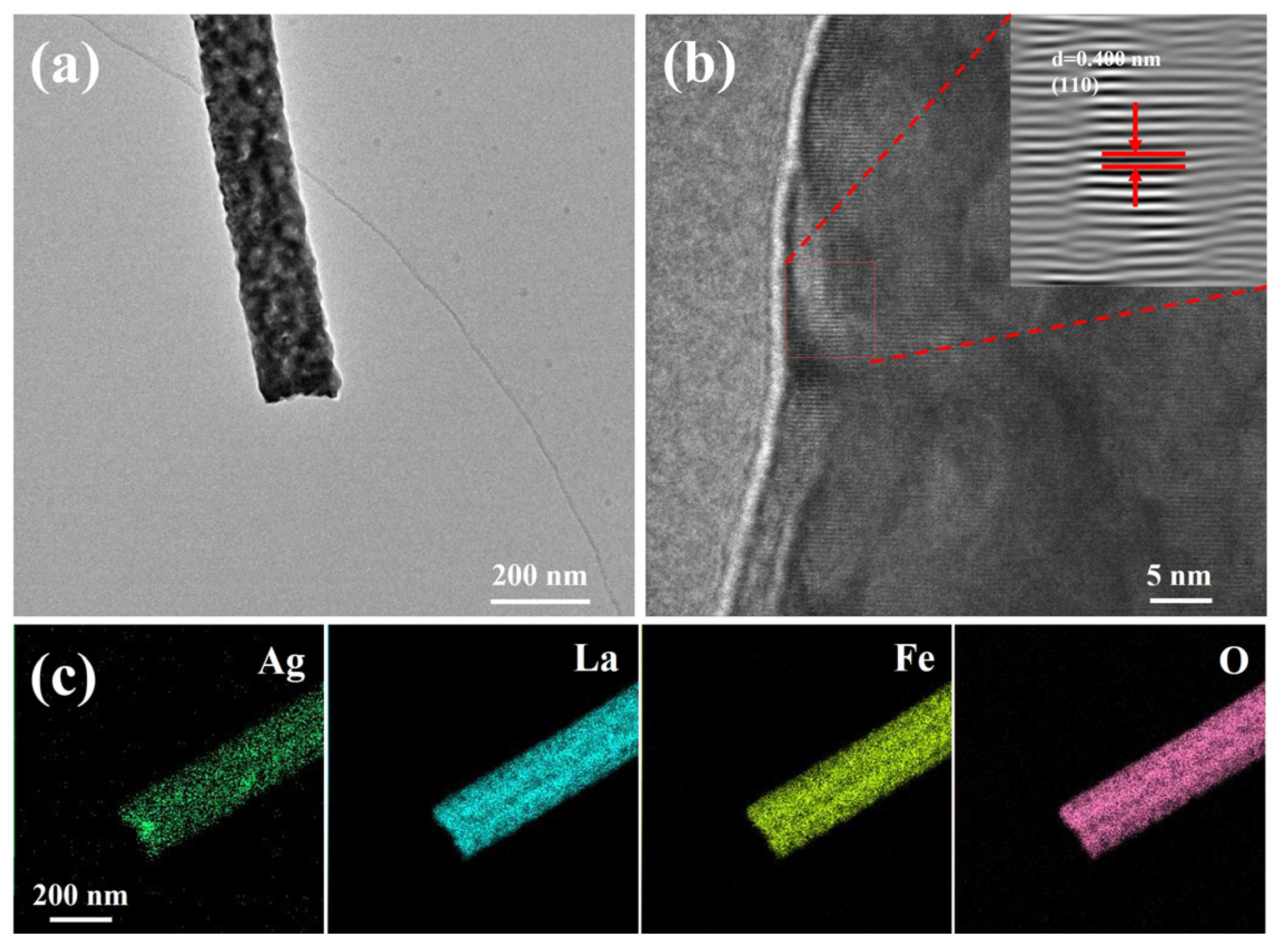
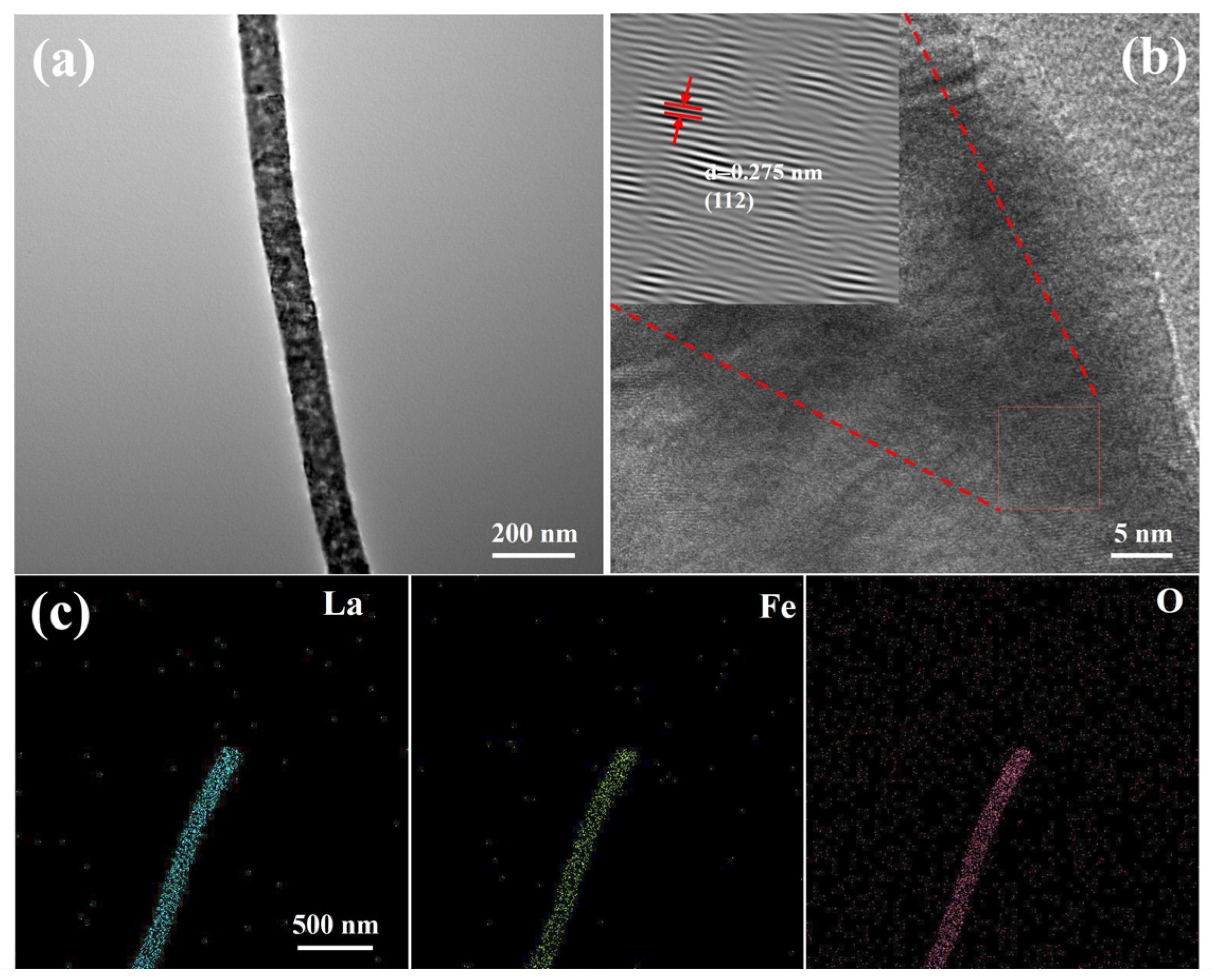
To further investigate the microstructural morphology and elemental distribution characteristics of the synthesized LaFeO3 and Ag0.025LaFeO3 NFs, TEM characterization was conducted on the two samples. Based on Figure 4a and Figure 5a, LaFeO3 and Ag0.025LaFeO3 exhibited nanofibrous structures that were in good agreement with those obtained from SEM characterization. The diameter values of LaFeO3 and Ag0.025LaFeO3 were about 100 and 160 nm, respectively. According to Figure 4b and Figure 5b, clear lattice fringes were visible in the high-resolution transmission electron microscopy (HRTEM) micrographs, where the lattice spacing of 0.275 and 0.400 nm matched well with the (112) and (110) crystal planes for LaFeO3 and Ag0.025LaFeO3 NFs. As shown in Figure 4c and Figure 5c, the elemental mapping images clearly demonstrated the homogeneous distribution of La, Fe, and O elements in the LaFeO3, as well as the La, Ag, Fe, and O elements in Ag0.025LaFeO3 NFs. Also, it further confirmed that the doped Ag ions were uniformly dispersed without obvious aggregation. The relatively weaker Ag signal observed at grain boundaries can be ascribed to the inhomogeneous incorporation of Ag dopant within the LaFeO3 lattice. The Ag species preferentially entered the perovskite lattice sites instead of accumulating as dense agglomerates on the surface.

2.3. XPS Analysis

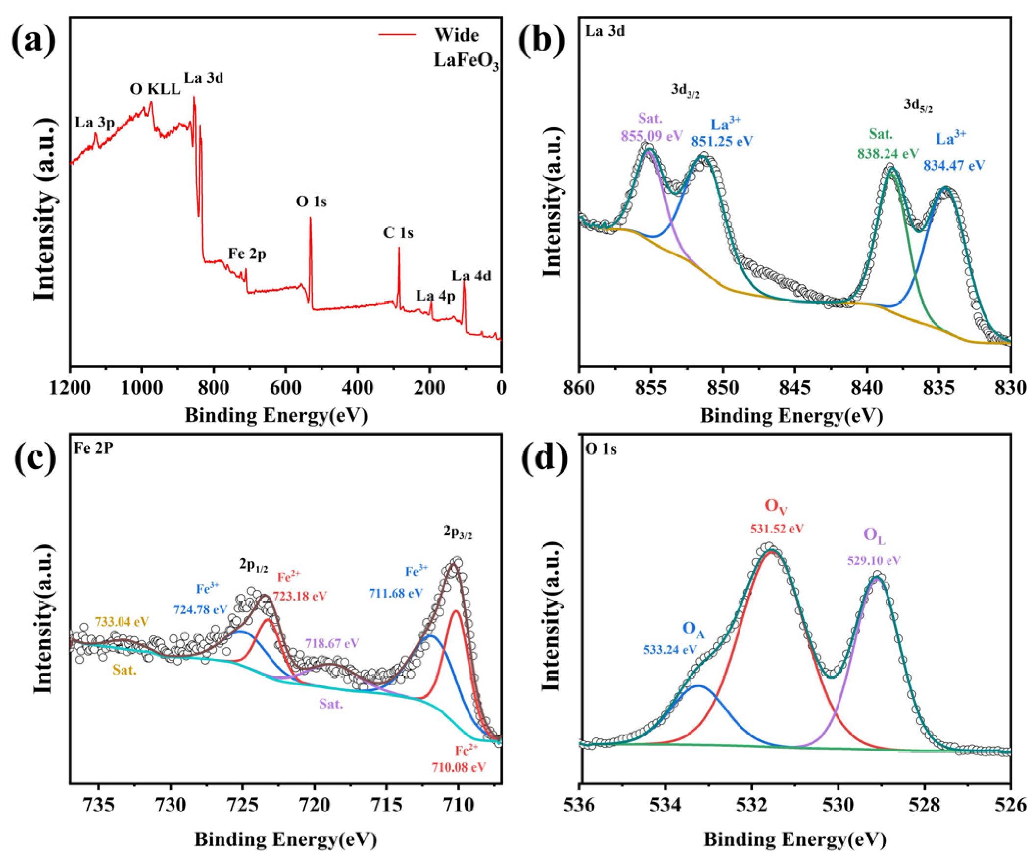
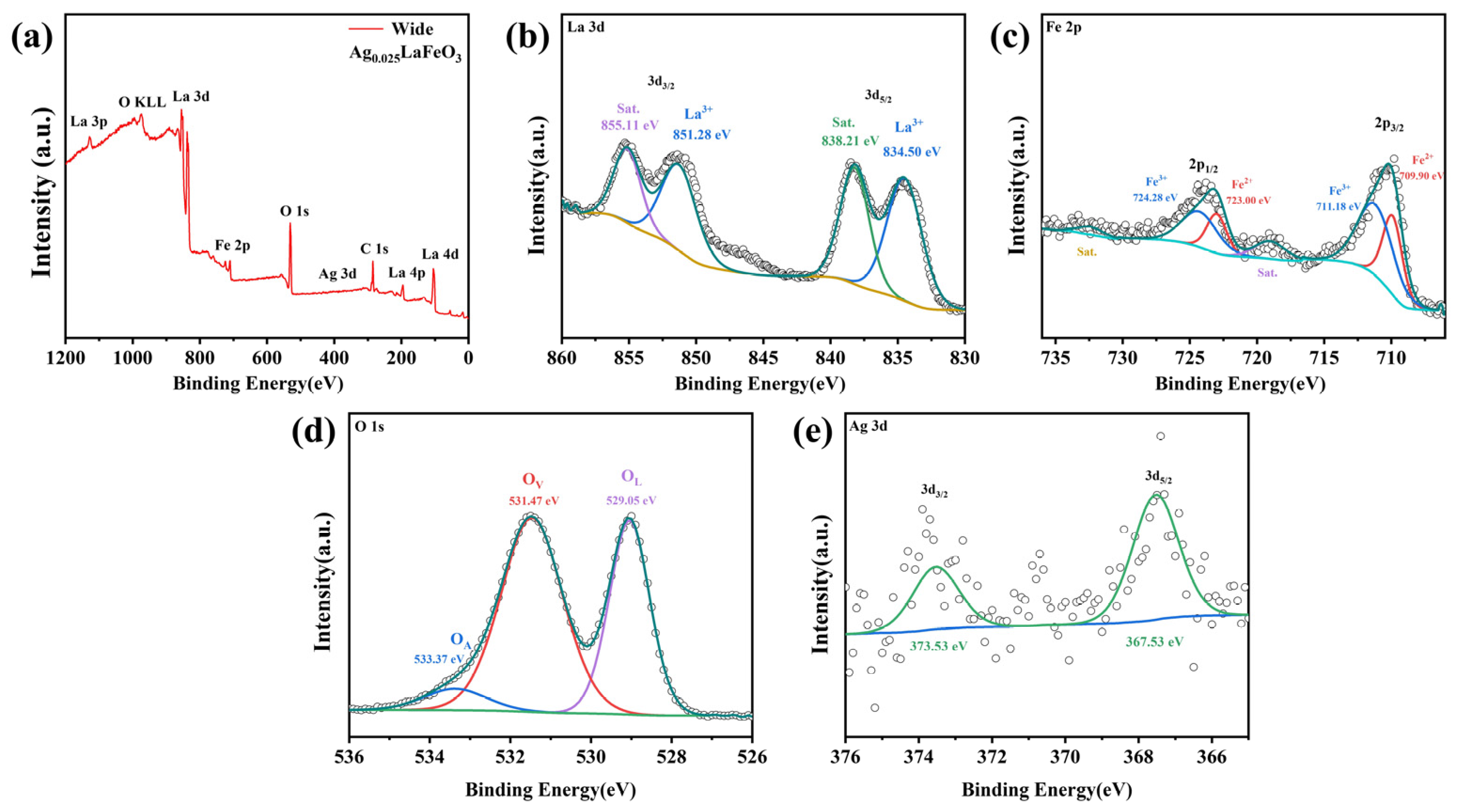
The chemical states and electronic structures of the elements contained in LaFeO3 and Ag0.025LaFeO3 NFs were investigated by means of XPS measurements. As illustrated in Figure 6a and Figure 7a, the full survey scan spectra confirmed the presence of La, Fe, and O in LaFeO3, as well as La, Fe, O, and Ag in Ag0.025LaFeO3. Adventitious carbon contamination was signaled by the observed C 1s peak, and this contamination was tentatively attributed to the substrate or instrumental components. High-resolution XPS spectra for La 3d, Fe 2p, O 1s, and Ag 3d are illustrated in Figure 6 and Figure 7. A good consistency was observed between the elemental mapping and XPS results. In the high-resolution La 3d XPS spectra of LaFeO3 and Ag0.025LaFeO3, four well-defined peaks can be observed in Figure 6b and Figure 7b. Two distinct peaks centered at roughly 834 and 851 eV were assigned to La 3d5/2 and La 3d3/2, respectively. The binding energy gap between these two peaks was approximately 17 eV, indicating a definitive hallmark of the La3+ valence state [16]. Spin–orbit interaction gave rise to a satellite peak at about 838 eV, while electron transfer between the O 2p valence band and La 4f energy level was responsible for the satellite peak at roughly 855 eV [17]. The Fe 2p spectra of LaFeO3 and Ag0.025LaFeO3 NFs, as shown in Figure 6c and Figure 7c, exhibited two main spin–orbit split regions, namely Fe 2p3/2 and Fe 2p1/2. The sub-peaks at 711 eV and 724 eV were attributed to Fe3+, and those at 710 eV and 723 eV were ascribed to Fe2+ [16]. Trivalent Fe was identified as the dominant valence state of the Fe component. Figure 6d and Figure 7d show the high-resolution XPS spectrum of the O 1s orbital for LaFeO3 and Ag0.025LaFeO3 NFs. Through peak-fitting analysis, the O 1s spectra can be deconvoluted into three characteristic components, namely lattice oxygen (O2−, denoted as OL) at a binding energy of 529 eV, surface-adsorbed oxygen or oxygen vacancy defects (O22−/O, denoted as OV) at 531 eV, and surface hydroxyl groups or adsorbed water (OH/H2O, denoted as OA) [6]. Figure 7e presents the high-resolution XPS spectrum of the Ag 3d orbital for Ag0.025LaFeO3 NFs. The characteristic peaks can be observed at the binding energies of 367.53 eV (Ag 3d5/2) and 373.53 eV (Ag 3d3/2), which confirms the presence of Ag+ in the Ag0.025LaFeO3 sample [18]. A comparison of the high-resolution O 1s spectra between the LaFeO3 and Ag0.025LaFeO3 revealed a slight leftward shift in the OL and OV peak positions for Ag0.025LaFeO3, demonstrating that Ag doping introduced lattice defects in LaFeO3. When Ag+ is doped into the A-site of LaFeO3 to substitute La3+, a charge imbalance is induced. To maintain the electrical neutrality of the perovskite lattice, the dominant charge compensation mechanisms include the reduction of partial Fe3+ to Fe2+ in the B-site and the formation of oxygen vacancies. Both EDS and XPS are recognized as semi-quantitative techniques. Noticeable modifications in magnetic behavior and carrier transport characteristics are observed upon Ag doping.

2.4. Raman Analyses

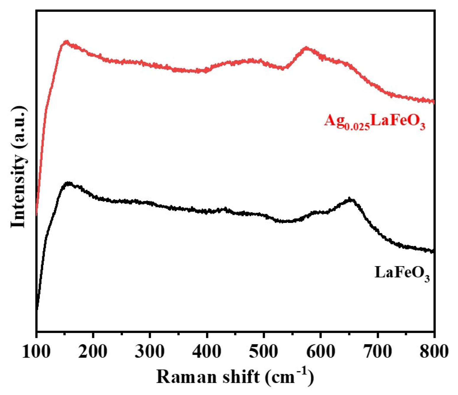
To investigate the chemical bonding states of LaFeO3 and Ag0.025LaFeO3, Raman spectroscopy characterization was performed. Both samples were tested at room temperature using a Raman spectrometer with a laser excitation wavelength of 633 nm, and the measurements were conducted in the range of 100–800 cm−1. The results are presented in Figure 8. An obvious peak at 154 cm−1 corresponded to the vibration of La-O [19]. The peak located in 258–300 cm−1 was assigned to the tilting vibration mode of FeO6, which enabled the determination of the degree of lattice distortion and tilting [19]. The bending vibration mode of FeO6 at 430 cm−1 can be seen. The single peak in the range of 612–650 cm−1 corresponded to the oxygen stretching vibration mode, and the strong peak in this region was generally associated with oxygen vacancies [20,21]. The changes in Raman peak intensity at 571 cm−1 and 494 cm−1 could originate from the replacement of La3+ by Ag+ [19].

2.5. FTIR Analyses

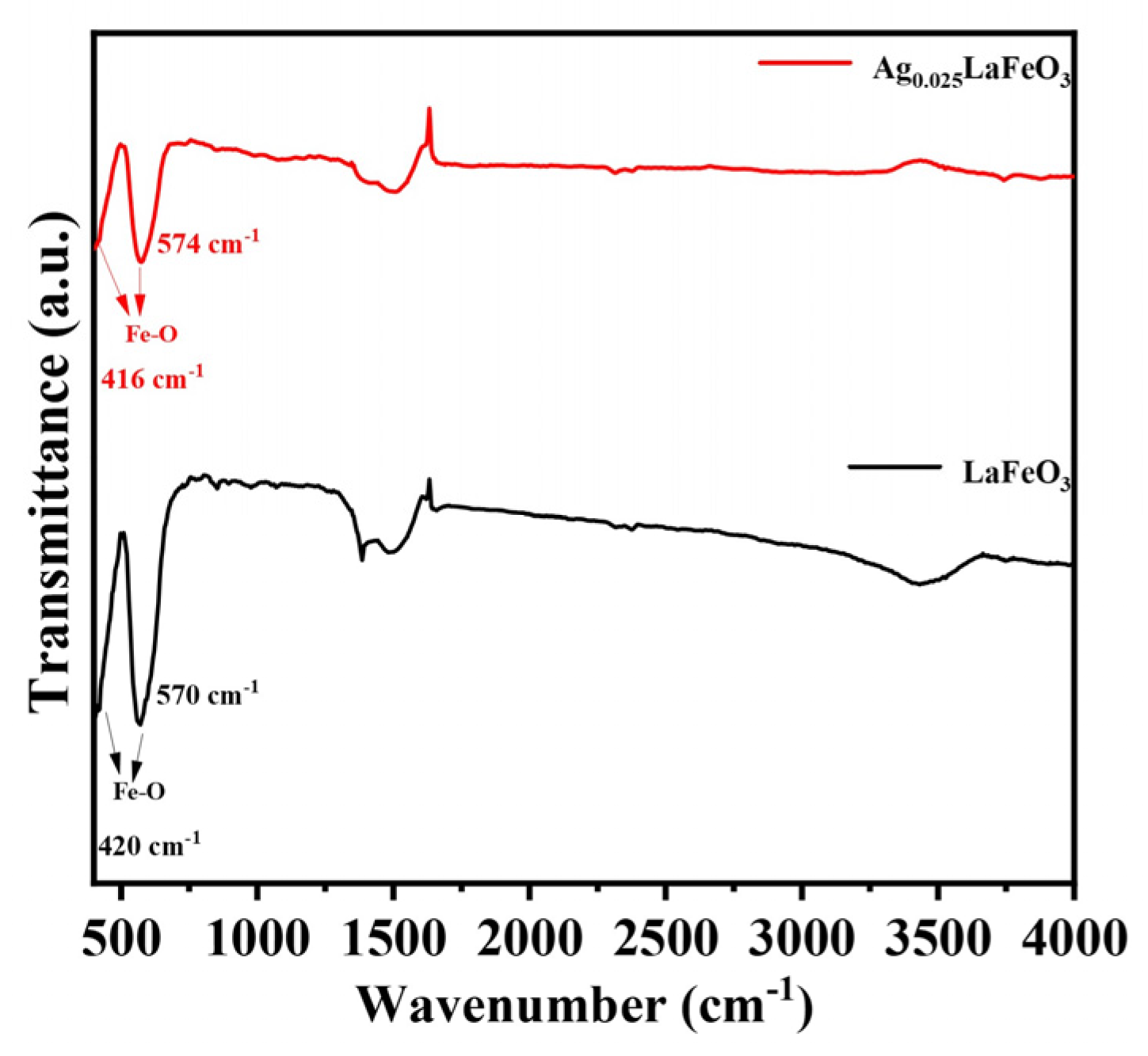
Fourier-transform infrared spectra of LaFeO3 and Ag0.025LaFeO3 are shown in Figure 9. The data were recorded in the wavenumber range from 400 to 4000 cm−1. The characteristic peaks located at about 420 and 570 cm−1 originated from the stretching vibration of Fe-O bonds [2,22]. Weak absorption signals near 3500 cm−1 and 1500 cm−1 corresponded to O-H stretching and water bending vibrations, respectively, originating from moisture adsorbed on the sample surface [2]. The peak at 1380 cm−1 was ascribed to monodentate carbonate species [2].

2.6. Conduction Mechanisms

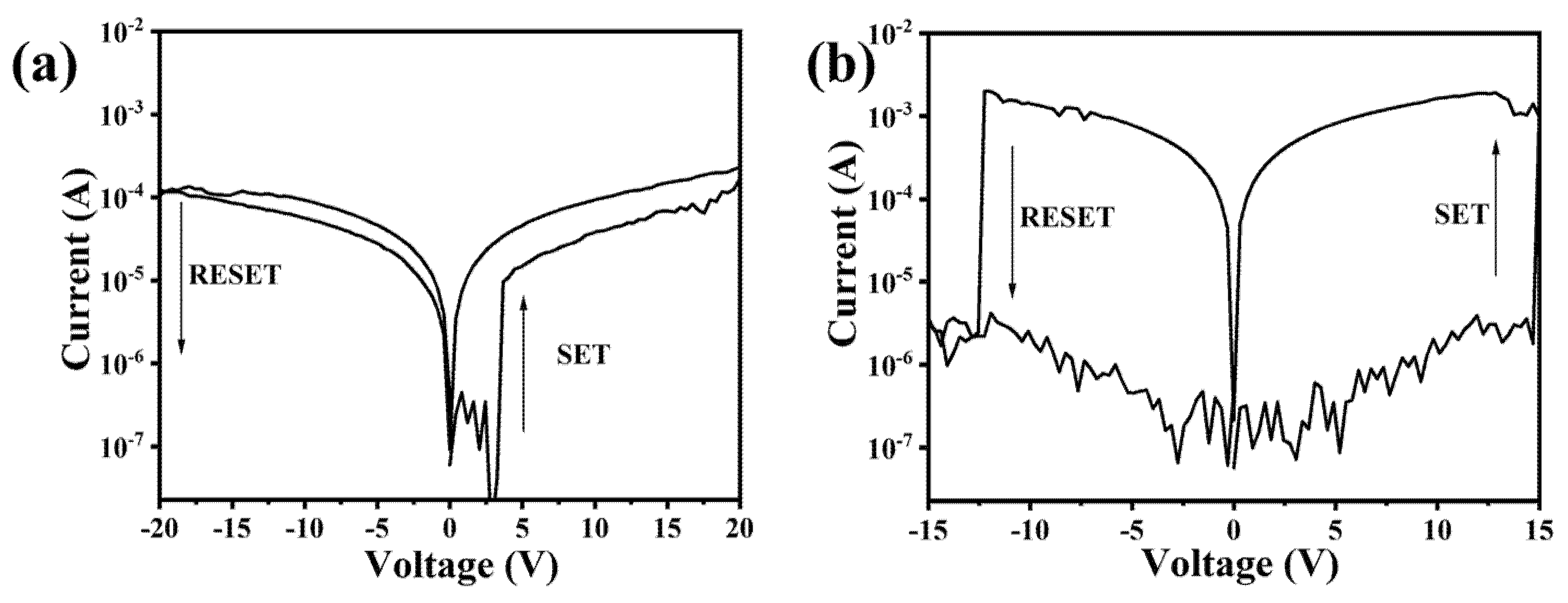
Ag/LaFeO3 NFs/Ag and Ag/Ag0.025LaFeO3 NFs/Ag devices based on LaFeO3 and Ag0.025LaFeO3 NFs were prepared, with the aim of studying their electrical conduction mechanisms. According to the I–V curves as shown in Figure 10, two devices presented bipolar resistive switching performance. The resistance changed from a high-resistance state (HRS) to a low-resistance state (LRS) at high positive voltage, while it changed from LRS to HRS at high negative voltage. A substantially low on/off ratio was observed in the LaFeO3 NF dielectric layer device relative to the Ag0.025LaFeO3 NF counterpart. The on/off ratio at +5 V of Ag/Ag0.025LaFeO3 NFs/Ag was 3.6 × 10³, while that of Ag/LaFeO3 NFs/Ag was 3.4. The radius and valence state of Ag+ differed from those of La3+ and Fe3+ in the LaFeO3 lattice. To maintain electrical neutrality after doping, the lattice generated more oxygen vacancies as charge compensation sites. The increased oxygen vacancy concentration within the Ag0.025LaFeO3 NFs was induced by Ag doping, which benefited the formation of conductive filaments and enhanced the migration ability of oxygen vacancies under applied voltage. The high oxygen vacancy concentration facilitated the formation of conductive filaments during the SET process and promoted complete rupture during the RESET process, thereby widening the resistance difference between the HRS and LRS and improving the on/off ratio [23]. The SET and RESET voltage values of Ag0.025LaFeO3 NFs were 14.7 and −12.3 V, while those of LaFeO3 NFs were 3.2 and −18.1 V. During the SET process, it was necessary not only to drive the migration of oxygen vacancies but also to facilitate the injection of Ag ions from the electrodes into Ag0.025LaFeO3 NFs. A relatively high voltage was thus required to enable the effective migration of Ag ions and the formation of conductive filaments. In the RESET process, the negative voltage should not only oxidize the oxygen vacancies but also drive the deintercalation of Ag ions from the filaments and their migration back to the electrodes. It also required a high RESET voltage [24,25].
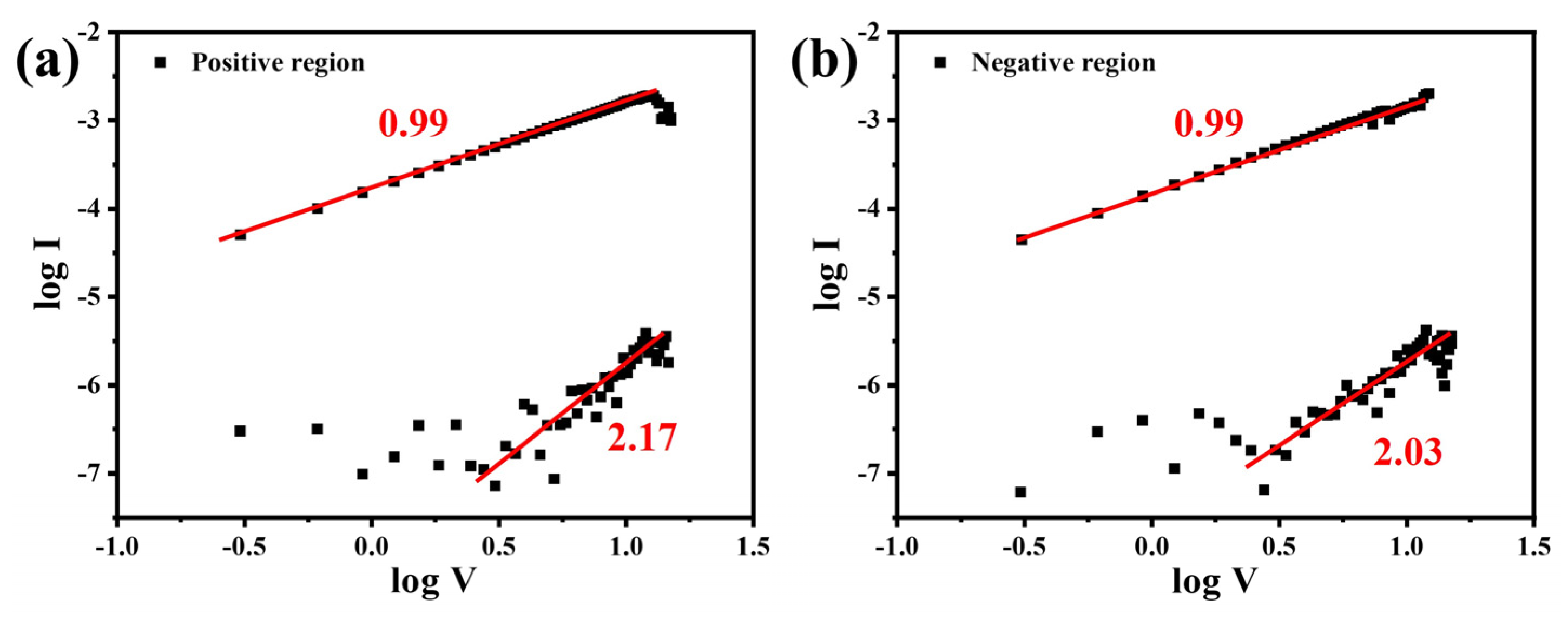
The double-logarithmic I–V curves were plotted to analyze the charge transport behavior of Ag0.025LaFeO3 NFs. Figure 11 shows the log–log I–V curves of Ag/Ag0.025LaFeO3 NFs/Ag in the positive- and negative-voltage regions. As shown in Figure 11a, they exhibited a distinct linear region before SET, indicating the ohmic conduction mechanism. After SET, the slope of 2.17 corresponded to the space-charge-limited current (SCLC) conduction mechanism, confirming that Ag doping introduced oxygen vacancies as carrier trap sites and that the Ag/Ag0.025LaFeO3 NFs/Ag device operated primarily via the SCLC mechanism [26]. As shown in Figure 11b, before RESET, the slope of 0.99 aligned with the ohmic conduction mechanism, demonstrating that carrier transport in this region was dominated by ohmic conduction. After RESET, the slope of 2.03 corresponded to the trap-filled SCLC conduction mechanism, verifying that Ag doping introduced oxygen vacancies as carrier trap sites and that the device was governed by the SCLC mechanism. The presence of traps further suppressed the current in the HRS, while the current in the LRS was amplified due to the high conductivity of conductive filaments, thus increasing the on/off ratio.
Oxygen vacancies were randomly distributed in Ag0.025LaFeO3 NFs at the initial state. An abundance of defect traps originating from oxygen vacancies dominated carrier capture, showing typical trap-controlled SCLC characteristics. When a positive voltage was applied to the device, a substantial number of oxygen vacancies were generated, which aggregated to form conductive filaments under the mediation of Ag ions. The resistance switched from the HRS to the LRS. Localized Joule heating played a critical role in this process. This thermal effect, mainly triggered by electron injection, led to the disappearance of oxygen ions at the interface between the electrode and the switching layer [27]. This phenomenon induced the formation of conductive filaments in Ag0.025LaFeO3 NFs, accompanied by the accumulation of oxygen vacancies at the interface, thus forming protruding filamentary pathways. These filamentary pathways then established serial interconnections, driving the device to shift from the HRS to the LRS, which marked the accomplishment of the SET procedure. During the RESET process, a negative voltage was applied to the device, which caused the rupture of oxygen vacancy-mediated conductive filaments, thus switching the device from the LRS to the HRS. During the SET process, the applied positive voltage facilitated the reduction of Fe3+ to Fe2+ in Ag0.025LaFeO3 NFs via the mediation of oxygen vacancies. Conversely, in the RESET process, the application of a negative voltage led to the dissolution of conductive filaments. As the device switched from the LRS to the HRS, the decrease in oxygen vacancy concentration triggered the re-oxidation of Fe2+ to Fe3+ [28,29].

2.7. Magnetic Property

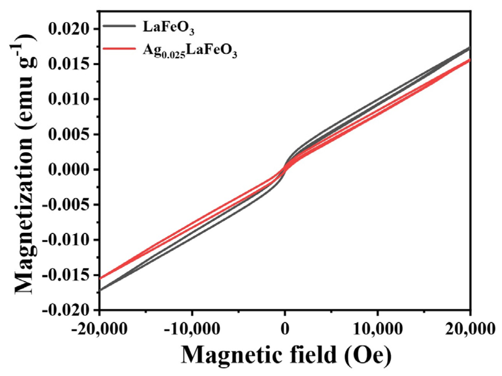
The hysteresis loops of LaFeO3 and Ag0.025LaFeO3 NFs measured at 300 K was shown in Figure 12. Under a 20,000/−20,000 Oe external magnetic field, the M-H loops showed no saturation, implying the coexistence of weak ferromagnetism and antiferromagnetism induced by antiferromagnetic spins [29]. The antiferromagnetic structure of LaFeO3 and Ag0.025LaFeO3 stemmed from two coplanar interpenetrating pseudo-rectangular FeO6 octahedra, with no magnetic interactions between La3+ and Fe3+ ions [30]. The pronounced weak ferromagnetism could be attributed to the super-exchange effect of Fe3+-O- Fe3+. The coercivity (Hc) and remanence (Mr) values of LaFeO3 were 150 Oe and 0.000494 emu g−1, while those of Ag0.025LaFeO3 were 200 Oe and 0.000404 emu g−1. The magnetization value of Ag0.025LaFeO3 was lower than that of LaFeO3. The 4d orbitals of Ag ions were fully occupied, with no unpaired electrons, thus exhibiting diamagnetic behavior. Ag doping induced lattice distortion and changes in the spin canting angle of LaFeO3. The radius of Ag+ was slightly larger than that of La3+, so doping caused lattice expansion and altered the Fe-O-Fe bond angle [31]. Consequently, this affected the strength of antiferromagnetic super-exchange interactions and antisymmetric exchange interactions, leading to a reduction in the spin canting angle, which directly weakened the net weak ferromagnetic moment and thus decreased the remanent magnetization. The introduction of Ag created a charge imbalance and resulted in the formation of oxygen vacancies or the conversion of partial Fe3+ to Fe2+. An appropriate concentration of oxygen vacancies can disrupt part of the antiferromagnetic coupling pathways and enhance ferromagnetism. The destroyed magnetic ordering or alteration of the contribution of Fe magnetic moments resulted in a decrease in the overall remanent magnetization [32,33].

3. Experimental and Methods

Sample fabrication was carried out using lanthanum nitrate hexahydrate (La(NO3)3·6H2O), iron(II) acetate (FeAc2), silver acetate (AgAc), polyvinylpyrrolidone (PVP, Mw ≈ 1,300,000, K88-96), and N, N-dimethylformamide (DMF). All chemicals were purchased from Aladdin Scientific Corp. Shanghai, China and used as received without undergoing any further purification treatment. La(NO3)3·6H2O, FeAc2, and AgAc worked as the precursor for the fabrication of Ag-doped LaFeO3, namely Ag0.025LaFeO3. Ag0.025LaFeO3 represents the nominal molar ratio of raw materials during synthesis, not a strictly charge-balanced structural formula. The samples were fabricated using an electrospinning technique. Addition of La(NO3)3·6H2O (1 mmol), FeAc2 (1 mmol), Ag (0.025 mmol), and PVP (0.5 g) to DMF (4.5 mL) and subsequent 12 h stirring afforded a clear and homogeneous electrospinning solution. Key electrospinning parameters included an applied voltage of 14 kV, a collector roller speed of 140 rpm, a tip-to-collector distance of 30 cm, and an ambient temperature of 40 °C. The as-prepared solution was initially transferred into a disposable syringe, which was subsequently mounted onto the electrospinning apparatus. Meanwhile, cleaned 1.5 cm ×1.5 cm silicon oxide on silicon (SiO2/Si) substrates were immobilized on the collector roller using conductive carbon adhesive tape. The precursor solution was then subjected to electrospinning onto the substrates under high-voltage conditions for 2 min, and the silicon wafers were subsequently retrieved. Following the preparation of the electrospun precursor NFs, these were placed in a muffle furnace and calcined at 700 °C for 180 min. The resultant Ag0.025LaFeO3 samples and the Ag0.025LaFeO3 NFs on SiO2/Si substrates were then obtained after cooling to room temperature. The reference control sample of LaFeO3 was prepared by the same method with La(NO3)3·6H2O (1 mmol) and FeAc2 (1 mmol).
Magnetron sputtering (JCP5000, Beijing Technol Science Co., Ltd., Beijng, China) was employed to deposit silver electrodes onto the SiO2/Si substrates with LaFeO3 and Ag0.025LaFeO3 NFs, followed by the assembly of planar-structured Ag/LaFeO3 NFs/Ag and Ag/Ag0.025LaFeO3 NFs/Ag devices. The silver electrodes were deposited via DC magnetron sputtering using a 99.99%-pure Ag target, which was obtained from ZhongNuo Advanced Material Technology Co., Ltd. Beijing, China. The key sputtering parameters were a sputtering power of 100 W, an argon flow rate of 50 sccm, a sputtering pressure of 0.1 Pa, a background vacuum of about 5 × 10⁻⁵ Pa, and a sputtering time of 1 min. The substrate was kept at room temperature with no applied bias voltage. The nominal thickness of the silver electrodes was about 500 nm.
The crystal structures of LaFeO3 and Ag0.025LaFeO3 were recorded by an X-ray powder diffractometer (XRD, Rigaku Smartlab, Tokyo, Japan) with Cu Kα radiation (λ = 1.5406 Å) over a 2θ range from 10° to 70°, and then Rietveld refinement was carried out using GSASII revision: 5775 (svn SVN version 5775) software. To characterize the morphological features of electrospun La(NO3)3-FeAc2-AgAc/PVP precursors and resultant Ag0.025LaFeO3 samples, scanning electron microscopy (SEM, Hitachi S-4800, Hitachinaka, Japan) and transmission electron microscopy (TEM, JEOL JEM F-200, Akishima, Japan) were utilized. The morphology of the Ag0.025LaFeO3 NFs on SiO2/Si substrate was examined by SEM. An energy-dispersive X-ray spectrometer attached to the TEM instrument was utilized for the assessment of elemental distribution profiles. The valence states and chemical compositions of Ag0.025LaFeO3 were examined via X-ray photoelectron spectroscopy XPS (Thermo ESCALAB 250xi, Waltham, MA, USA), where binding energy calibration was performed using the C 1s peak at 284.8 eV as the standard reference. Raman spectra were recorded on a Raman spectroscope (Renishaw InVia, Gloucestershire, UK) equipped with a laser excitation wavelength of 633 nm. Spectra were collected in the range of 100–800 cm−1 at room temperature under ambient atmosphere. Fourier-transform infrared spectroscopy test was recorded with a Fourier Transform Infrared Spectroscope (FTIR, Shimadzu IRAffinity-1S, Kyoto, Japan) in the range of 400–4000 cm−1 by the standard KBr pellet method at room temperature.
A semiconductor characterization system (4200A-SCS, Keithley, A Tektronix Company, Beaverton, OR, USA) was employed to characterize the resistive switching behavior of LaFeO3 and Ag0.025LaFeO3.
A Quantum Design SQUID vibrating sample magnetometer (SQUID-VSM, San Diego, CA, USA) was employed to investigate the magnetic characteristics of LaFeO3 and Ag0.025LaFeO3. The magnetic field-dependent magnetization (M-H) curves of the samples were acquired at 300 K.

4. Conclusions

Through electrospinning, this work not only achieved the synthesis of one-dimensional Ag-doped LaFeO3 NFs but also systematically elucidated their structural evolution, conduction behavior, and magnetic properties, further revealing the critical influence of Ag doping on the microstructure and multifunctional performance of LaFeO3 NFs. Rietveld fitting of the XRD patterns corroborated the orthorhombic crystal structure. The diameter values of LaFeO3 and Ag0.025LaFeO3 were about 160 and 100 nm, respectively. XPS results revealed that Fe exhibited a mixed oxidation state of +3 and +2, La remained predominantly in the +3 oxidation state, and O was mainly in the −2 state, with some contributions from oxygen vacancies and surface-adsorbed oxygen species. For Ag0.025LaFeO3 NFs, the conduction was dominated by the ohmic conduction mechanism in the LRS, while it was governed by space-charge-limited current conduction in the HRS. The Ag0.025LaFeO3 NF device showed a high on/off ratio, which improved the reliability of stored signals. It is thus indicative of the favorable prospect of Ag0.025LaFeO3 NFs for resistive random-access memory devices. The coercivity and remanence values of LaFeO3 were 150 Oe and 0.000494 emu g−1, while those of Ag0.025LaFeO3 were 200 Oe and 0.000404 emu g−1. This study demonstrates great application potential in magnetoresistive random-access memory devices.

Author Contributions

C.S.: Methodology, Investigation, Writing—original draft. J.X.: Methodology, Data curation, Investigation. H.L.: Resources, Methodology. Q.H.: Supervision, Data curation, Writing—original draft, Writing—review and editing. All authors have read and agreed to the published version of the manuscript.

Funding

This work was financially supported by the National Natural Science Foundation of China (22261043) and the Inner Mongolia Autonomous Region Key Laboratory Innovation Platform Construction Project (KJJH2402, SYS25003).

Institutional Review Board Statement

Not applicable.

Informed Consent Statement

Not applicable.

Data Availability Statement

The authors confirm that the data supporting the findings of this study are available within the article. In addition, the datasets used and/or analyzed during the current study are available from the corresponding author on reasonable request.

Acknowledgments

We are deeply grateful to Yin Wang for his valuable assistance and support in the transmission electron microscopy (TEM) characterization and measurements.

Conflicts of Interest

The authors declare no conflicts of interest.

References

  1. Yang, Y.; Guo, P.; Xie, Y.; Lu, Y.; Luo, Y. Electronic and magnetic properties of LaRuO3 and LaFeO3: Orbital order and canted antiferromagnetism. Comp. Mater. Sci. 2021, 200, 110839. [Google Scholar] [CrossRef]
  2. Chumakova, V.; Marikutsa, A.; Platonov, V.; Khmelevsky, N.; Rumyantseva, M. Distinct roles of additives in the improved sensitivity to CO of Ag- and Pd-modified nanosized LaFeO3. Chemosensors 2023, 11, 60. [Google Scholar] [CrossRef]
  3. Humayun, M.; Li, Z.; Israr, M.; Khan, A.; Luo, W.; Wang, C.; Shao, Z. Perovskite Type ABO3 oxides in photocatalysis, electrocatalysis, and solid oxide fuel cells: State of the art and future prospects. Chem. Rev. 2025, 125, 3165–3241. [Google Scholar] [CrossRef]
  4. Patil, S.S.; Shinde, K.P.; Patil, A.P.; Abbas, M.A.; Nadargi, J.D.; Mujawar, S.H.; Mulla, I.S.; Kim, K.B.; Suryavanshi, S.S. Dual-functional LaFeO3 perovskites via auto-combustion and hydrothermal methods for gas sensing and photocatalytic dye degradation. Inorg. Chem. Commun. 2025, 182, 115493. [Google Scholar] [CrossRef]
  5. Musa, A.A.; Hafeez, H.Y.; Mohammed, J.; Ndikilar, C.E.; Suleiman, A.B. LaFeO3 perovskite: A hotspot into sustainable energy development via photocatalytic water splitting. Inorg. Chem. Commun. 2026, 185, 116020. [Google Scholar] [CrossRef]
  6. Wu, J.; Wan, Y.; Wang, Z.; Wang, Y.; Luo, Q.; Feng, C.; Yoshinobu, T. Loose Ag-doped LaFeO3 nanotubes-based gas sensor for excellent acetic acid sensing. IEEE Sens. J. 2024, 24, 5821–5829. [Google Scholar] [CrossRef]
  7. Schmitt, R.; Kubicek, M.; Sediva, E.; Trassin, M.; Weber, M.C.; Rossi, A.; Hutter, H.; Kreisel, J.; Fiebig, M.; Rupp, J.L.M. Accelerated ionic motion in amorphous memristor oxides for nonvolatile memories and neuromorphic computing. Adv. Funct. Mater. 2018, 29, 1804782. [Google Scholar] [CrossRef]
  8. Shringi, A.K.; Betal, A.; Sahu, S.; Saliba, M.; Kumar, M. Resistive switching and synaptic behavior of perovskite lanthanum orthoferrite thin film for neuromorphic computing. IEEE Trans. Electron Devices 2022, 69, 6465–6470. [Google Scholar] [CrossRef]
  9. Qiu, C.; Wang, L.; Chen, R.; Wu, G.; Zhang, J.; Ding, J.; Li, J.; Zhang, J.; Wan, H.; Guan, G. Chemical-tailoring LaFeO3 nanofibers enable efficient dispersion of Ag nanoparticles for photocatalytic CO2 conversion to CH3OH. J. Environ. Chem. Eng. 2025, 13, 119577. [Google Scholar] [CrossRef]
  10. Yu, J.; Wang, C.; Yuan, Q.; Yu, X.; Wang, D.; Chen, Y. Ag-modified porous perovskite-type LaFeO3 for efficient ethanol detection. Nanomaterials 2022, 12, 1768. [Google Scholar] [CrossRef]
  11. Sun, B.; Chen, R.; Liu, M.; Song, P. Highly sensitive formaldehyde gas sensor based on Au nanoparticle functionalized 1D LaFeO3 nanofibers. Microchem. J. 2025, 211, 113140. [Google Scholar] [CrossRef]
  12. Yu, S.; Bao, Y.; Zhang, W.; Gao, L.; Guo, R.; Liu, C. Tuning the structure of lychee-like LaFeO3 for adjusting infrared stealth properties. J. Colloid Interface Sci. 2026, 708, 139848. [Google Scholar] [CrossRef]
  13. Ren, K.; Wang, T.; Shi, W.; Luo, H.; Liang, J.; Kong, J. Coordination chemistry modulation of LaFeO3 as a promising anode material for nickel-metal batteries. Adv. Sustain. Syst. 2025, 9, e00445. [Google Scholar] [CrossRef]
  14. James, A.; Ray, S.; Rodney, J.; Carva, K.; Udayashankar, N.K.; Kim, B.C. Cu- and Bi-codoped LaFeO3-decorated MXene nanosheets for photo-Fenton catalysis and hydrogen evolution. ACS Appl. Nano Mater. 2025, 8, 18333–18347. [Google Scholar] [CrossRef]
  15. Ji, D.; Lin, Y.; Guo, X.; Ramasubramanian, B.; Wang, R.; Radacsi, N.; Jose, R.; Qin, X.; Ramakrishna, S. Electrospinning of nanofibers. Nat. Rev. Methods Primers 2024, 4, 1. [Google Scholar] [CrossRef]
  16. Jeong, J.; Song, C.; Kim, K.; Sigmund, W.; Yoon, J. Effect of Mn doping on particulate size and magnetic properties of LaFeO3 nanofiber synthesized by electrospinning. J. Alloys Compd. 2018, 749, 599–604. [Google Scholar] [CrossRef]
  17. Ding, Z.; Chen, Q.; Zhang, H.; Wang, W.; Zhang, D. Carbon dioxide gas sensor based on the LaCoO3/MXene heterojunction. ACS Appl. Nano Mater. 2025, 8, 12057–12064. [Google Scholar] [CrossRef]
  18. Hu, B.; Liu, Y.; Zhang, B.; Guo, F.; Zhang, M.; Hao, L. Ag doping modified SnSe-based flexible memristors for artificial optoelectronic synapses. ACS Appl. Electron. Mater. 2024, 6, 8171–8179. [Google Scholar] [CrossRef]
  19. Zhang, L.; Yang, Y.; Tian, J.; Li, J.; Chen, G.; Zhou, L.; Sun, Y.; Qiu, Y. Selective photocatalytic reduction of CO2 to syngas over tunable metal-perovskite interface. ChemSusChem 2022, 15, e202102729. [Google Scholar] [CrossRef]
  20. Ali, S.M.; El Mansop, M.A.; Galal, A.; Abd El Wahab, S.; El-Etr, W.; Zein El-Abdeen, H. A correlation of the adsorption capacity of perovskite/biochar composite with the metal ion characteristics. Sci. Rep. 2023, 13, 9466. [Google Scholar] [CrossRef]
  21. Eyméoud, P.; Turquat, C.; Pardanaud, C.; Leroux, C.; Merlen, A. Raman spectroscopic detection of vacancies in LaFeO3. Mater. Lett. 2023, 330, 133296. [Google Scholar] [CrossRef]
  22. Manzoor, S.; Husain, S. Analysis of Zn substitution on structure, optical absorption, magnetization, and high temperature specific heat anomaly of the nano-crystalline LaFeO3. J. Appl. Phys. 2018, 124, 065110. [Google Scholar] [CrossRef]
  23. Wu, C.; Lin, C.; Chen, P.; Chang, T.; Zhou, K.; Chen, W.; Tan, Y.; Yeh, Y.; Chou, S.; Huang, H.; et al. Realizing forming-free characteristic by doping Ag into HfO2-based RRAM. Appl. Phys. Express 2021, 14, 041008. [Google Scholar] [CrossRef]
  24. Lin, C.; Chang, Y. Formation and rupture of Ag conductive bridge in ZrO2-based resistive switching memory. J. Nanosci. Nanotechnol. 2012, 12, 2437–2441. [Google Scholar] [CrossRef]
  25. Gorshkov, O.; Filatov, D.; Koveshnikov, S.; Shenina, M.; Soltanovich, O.; Shengurov, V.; Denisov, S.; Chalkov, V.; Antonov, I.; Pavlov, D.; et al. Bipolar resistive switching in memristors based on Ge/Si(001) epitaxial layers. J. Phys. Conf. Ser. 2020, 1695, 012158. [Google Scholar] [CrossRef]
  26. He, H.; Gao, Y.; Li, T.; Lin, Y.; Huang, Q.; He, R.; Li, J.; Liu, Y.; Pan, J. The shunt conductive effect of Ag doped RRAM via a qualitative circuit model. Appl. Phys. A 2024, 130, 761. [Google Scholar] [CrossRef]
  27. Zhuang, P.; Ma, W.; Liu, J.; Cai, W.; Lin, W. Progressive RESET induced by Joule heating in hBN RRAMs. Appl. Phys. Lett. 2021, 118, 143101. [Google Scholar] [CrossRef]
  28. Wang, L.; Yang, T.; Ju, Y.; Wen, D. First-principles study of the electronic properties of egg albumen optoelectronic artificial synapses by carbon nanotube insertion. Adv. Electron. Mater. 2024, 10, 2300631. [Google Scholar] [CrossRef]
  29. Terabe, K.; Tsuchiya, T.; Yang, R.; Aono, M. Nanoionic devices enabling a multitude of new features. Nanoscale 2016, 8, 13873. [Google Scholar] [CrossRef]
  30. Huang, L.; Cheng, L.; Pan, S.; Yao, Q.; Long, Q.; Wang, M.; Chen, Y.; Zhou, H. Influence of A-site doping barium on structure, magnetic and microwave absorption properties of LaFeO3 ceramics powders. J. Rare Earths 2022, 40, 1106–1117. [Google Scholar] [CrossRef]
  31. Al-Mamari, R.T.; Widatallah, H.M.; Elzain, M.E.; Gismelseed, A.M.; Al-Rawas, A.D.; Al-Harthi, S.H.; Myint, M.T.Z.; Al-Saqri, N.; Al-Abri, M. Core and surface structure and magnetic properties of mechano-synthesized LaFeO3 nanoparticles and their Eu3+-doped and Eu3+/Cr3+-co-doped variants. Sci. Rep. 2024, 14, 14770. [Google Scholar] [CrossRef]
  32. Guigoz, V.; Bruyère, S.; Migot, S.; Schneider, R.; Gries, T. Copper substitution in lanthanum-deficient LaFeO3 perovskites for enhanced photoelectrochemical solar hydrogen production. Int. J. Hydrogen Energy 2025, 148, 15007. [Google Scholar] [CrossRef]
  33. Sun, H.; Yin, C.; Attfield, J.P.; Yang, M. Tunable magnetoresistive gas sensing enabled by La-deficient LaFeO3. ACS Sens. 2025, 10, 6800–6807. [Google Scholar] [CrossRef]
Figure 1. The schematic illustration of Ag/Ag0.025LaFeO3 NFs/Ag devices.
Molecules 31 01174 g001
Figure 2. Rietveld refined X-ray diffraction patterns of (a) LaFeO3 and (b) Ag0.025LaFeO3.
Molecules 31 01174 g002
Figure 3. SEM images of (a1) La(NO3)3-FeAc2/PVP precursor, (a2) LaFeO3 NFs, (b1) La(NO3)3-FeAc2-AgAc/PVP precursor, (b2) Ag0.025LaFeO3 NFs, (c1) La(NO3)3-FeAc2/PVP precursor on SiO2/Si, (c2) LaFeO3 NFs on SiO2/Si, (d1) La(NO3)3-FeAc2-AgAc/PVP precursor on SiO2/Si, and (d2) Ag0.025LaFeO3 NFs on SiO2/Si.
Molecules 31 01174 g003
Figure 4. (a) TEM image, (b) HRTEM image, and (c) elemental mapping images of LaFeO3 NF. Inset is the lattice fringe image.
Molecules 31 01174 g004
Figure 5. (a) TEM image, (b) HRTEM image, and (c) elemental mapping images of Ag0.025LaFeO3 NF. Inset is the lattice fringe image.
Molecules 31 01174 g005
Figure 6. (a) Survey scan, (b) La 3d, (c) Fe 2p, and (d) O 1s XPS profiles of LaFeO3 NFs.
Molecules 31 01174 g006
Figure 7. (a) Survey scan, (b) La 3d, (c) Fe 2p, (d) O 1s and (e) Ag 3d XPS profiles of Ag0.025LaFeO3 NFs.
Molecules 31 01174 g007
Figure 8. Raman spectra of LaFeO3 and Ag0.025LaFeO3 NFs.
Molecules 31 01174 g008
Figure 9. FTIR spectra of LaFeO3 and Ag0.025LaFeO3 NFs.
Molecules 31 01174 g009
Figure 10. I–V curves (a) Ag/LaFeO3 NFs/Ag and (b) Ag/Ag0.025LaFeO3 NFs/Ag.
Molecules 31 01174 g010
Figure 11. Log–log I–V curves of Ag/Ag0.025LaFeO3 NFs/Ag in (a) positive-voltage region and (b) negative-voltage region.
Molecules 31 01174 g011
Figure 12. Magnetic hysteresis loops of LaFeO3 and Ag0.025LaFeO3 NFs at 300 K.
Molecules 31 01174 g012
Table 1. Lattice parameters of LaFeO3 and Ag0.025LaFeO3.
Samplea (Å)b (Å)c (Å)αβγV(Å)3Crystallite Size (nm)GOFRwp (%)χ2
LaFeO35.57205.57177.861490°90°90°244.061220.733.660.53
Ag0.025LaFeO35.56225.59337.853890°90°90°244.34023.90.803.830.64
GOF value represents the goodness of fit. Rwp is the weighted reliable factor of the profile. χ is the Chi-squared value.
Disclaimer/Publisher’s Note: The statements, opinions and data contained in all publications are solely those of the individual author(s) and contributor(s) and not of MDPI and/or the editor(s). MDPI and/or the editor(s) disclaim responsibility for any injury to people or property resulting from any ideas, methods, instructions or products referred to in the content.