Abstract
Photocatalytic hydrogen evolution from water is a sustainable approach to producing clean energy and promoting sustainable development. However, the low efficiency of photocatalysts under visible light and even near-infrared irradiation remains the current bottleneck in photocatalytic overall water splitting (POWS). Herein, we introduce an Al2O3/InP/Al photocatalyst with high efficiency and stability, which achieved an apparent quantum efficiency of 0.97% at 500 nm and operated for 10 h without significant performance decay. The high quantum efficiency and stability are attributed to the combination of the electron-rich Al reflective layer and Al2O3 protective layer coating, which synergistically facilitate charge separation. Additionally, the newly generated O2 from water over the Al2O3/InP/Al photocatalyst was removed under reduced pressure, thus inhibiting InP photocorrosion and enabling POWS under visible light irradiation. This study offers valuable insights for the development of efficient solar photocatalysts for water splitting.
1. Introduction
The overconsumption of fossil fuels necessitates a transition to renewable energy to mitigate climate change and achieve net-zero emissions [1]. Solar energy is a promising candidate due to its abundance and vast potential, but its intermittency requires efficient energy storage [2]. Hydrogen, an energy carrier with high mass-energy density and zero-carbon emissions upon combustion, is an ideal medium for this purpose [3]. Solar-driven POWS offers a sustainable pathway for producing green hydrogen, directly addressing the challenges of the energy crisis and environmental pollution [4,5,6]. Since Fujishima and Honda reported that photocatalytic water splitting occurs on TiO2 photoelectrodes [7], substantial efforts have been devoted to developing efficient photocatalysts for the hydrogen evolution reaction (HER). However, the solar-to-hydrogen (STH) efficiency remains low in most systems, far from the 10% threshold required for techno-economic viability [8]. A primary reason is the narrow spectral response of stable wide-bandgap materials, such as SrTiO3 [9], Ta2O5 [10], In2O3 [11], and Al2O3 [12], which are active in the UV region. Some visible-light-active semiconductors, such as SnS2 [13], CdS [14], ZnIn2S4 [15], and g-C3N4 [16], are often unstable in water and susceptible to photocorrosion. Notably, visible and infrared light counts for ~95% of AM1.5G, and harvesting these spectral regions may substantially improve the photocatalytic HER performance.
Indium phosphide (InP) is a narrow bandgap (~1.35 eV) semiconductor with efficient light absorption, high carrier mobility, and proven efficiency in thin-film solar cells (PCE up to 29.6%) [17,18,19,20]. These properties make it a promising candidate to address the spectral limitation. However, the low-valence state V-group element P is easily oxidized under light irradiation in aqueous solutions. Coating stable metal oxides, such as TiO2 [21], ZnO [22], and Al2O3 [23] onto III–V semiconductor surfaces, is a widely adopted strategy to prevent corrosion due to its low cost. Among them, Al2O3 is extensively used for interface passivation and photocatalytic HER, exhibiting excellent stability and charge transport [24,25,26,27]. Additionally, the efficiency of photoinduced carrier separation in photocatalysts is crucial for the performance of POWS. Recent advancements in metal–semiconductor junction architectures, with their unique charge separation and enhanced light-harvesting capabilities, offer a promising solution to this bottleneck [28,29]. In such systems, metallic layers (e.g., Al) act as reflective mirrors to prolong light pathways and improve photon utilization, facilitating efficient charge separation via Schottky junction formation [30,31].
In this work, we report the synthesis of efficient Al2O3/InP/Al photocatalysts for POWS via in situ growth of InP on the surface of electron-rich metallic Al, which is typically employed as a rear-surface reflector to enhance light absorption efficiency and simultaneously forms a metal-semiconductor junction that improves the separation efficiency of photogenerated carriers. To prevent the corrosion of InP, a thin Al2O3 shell coated on its surface significantly improves the stability of InP during photocatalytic water splitting. Additionally, a reduced-pressure system was employed to transfer hydrogen and oxygen generated within the reaction system, maintaining a low-pressure environment. This system significantly inhibits H2–O2 recombination on the surface of Al2O3/InP/Al, enhancing photocatalytic efficiency. This study demonstrated that the Al2O3/InP/Al photocatalyst exhibits an enhanced photocatalytic H2 production performance compared to bare InP, presents a high apparent quantum efficiency (AQE) (approximately 0.97% at 500 nm), and shows no significant performance decay after continuous illumination for 10 h. This work offers a potential avenue for solar energy conversion and storage by developing a novel approach to constructing an efficient and stable photocatalyst for water splitting.
2. Results and Discussion
2.1. XRD Analysis
The crystal structure of Al substrate, InP, InP/Al, and 0.6%Al2O3/InP/Al catalysts was analyzed using X-ray powder diffraction (XRD), and the results are shown in Figure 1. The Al substrate exhibits four intense diffraction peaks at 2θ = 38.5°, 44.7°, 65.1°, and 78.2°, correspond to the (111), (200), (220), and (311) crystal planes of the cubic phase Al according to JCPDS card No. 89-4037 (Figure S1) [32]. InP was used as the reference, which presents cubic phase InP, and the diffraction peaks at 26.3°, 30.4°, 43.6°, 51.6°, and 69.8° correspond to the (111), (200), (220), (311), and (331) crystal planes of cubic phase InP according to JCPDS card No. 73-1983 (Figure S2) [33]. After the growth of InP on the Al substrate, the InP/Al composite catalyst exhibits characteristic diffraction peaks of both InP and Al. Four strong diffraction peaks located at 38.5°, 44.7°, 65.1°, and 78.2° can be indexed to the (111), (200), (220), and (311) crystal planes of cubic Al. Three weak diffraction peaks are observed at 26.3°, 43.6°, and 51.6°, which can be assigned to the (111), (220), and (311) crystal planes of cubic InP. The above results confirm that an InP layer was successfully grown on the Al substrate via the phosphorization process. After constructing an Al2O3 protective layer on the InP/Al surface, the diffraction pattern of the 0.6%Al2O3/InP/Al composite was nearly identical to that of InP/Al, and no characteristic peaks of Al2O3 were found, which may be due to the lower surface Al2O3 content.
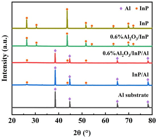
Figure 1.
XRD patterns of Al substrate, InP, InP/Al, and 0.6%Al2O3/InP/Al. Cubic-phase Al and cubic-phase InP are marked by purple diamond and orange circle symbols, respectively.
2.2. Morphological Analysis
The morphology of Al substrate, InP, InP/Al, and 0.6%Al2O3/InP/Al was investigated using transmission electron microscopy (TEM) and high-resolution transmission electron microscopy (HR-TEM). Figure 2A shows the TEM image of InP surface morphology, which has smooth edges but irregularities. Figure 2E displays the HR-TEM image of InP, exhibiting two crystal planes of cubic InP, (111) and (220), with corresponding lattice spacings of 0.339 nm and 0.208 nm, respectively. The Al substrate exhibits irregular morphology with smooth edges (Figure 2B). The HR-TEM image corresponding to the Al substrate (Figure 2F) reveals the (111) plane of cubic Al (d111 = 0.234 nm). The InP/Al sample also exhibits an irregular morphology (Figure 2C). HR-TEM imaging (Figure 2G) presents two lattice fringes with lattice spacings of 0.339 nm and 0.234 nm. These spacings correspond to the (111) crystal plane of cubic InP and cubic Al, respectively. The presence of both sets of lattice fringes indicates that InP was grown on the Al surface. After loading Al2O3 on the surface of InP/Al, the surface of the 0.6%Al2O3/InP/Al sample became rougher compared to the InP/Al sample (Figure 2D), and the morphological change may be due to the growth of the Al2O3 protective layer on the InP/Al surface. In the HR-TEM image of the 0.6%Al2O3/InP/Al sample (Figure 2H), InP and Al can be observed, but no lattice fringes attributable to crystalline Al2O3 are detected. Notably, an amorphous shell is observed at the edge of 0.6%Al2O3/InP/Al, suggesting Al2O3 deposition [24]. Additionally, the Al, In, P, and O elements are uniform in 0.6%Al2O3/InP/Al, indicating that the 0.6%Al2O3/InP/Al photocatalyst has been successfully synthesized by coating the Al2O3 shell on the InP/Al surface (Figure 2J).
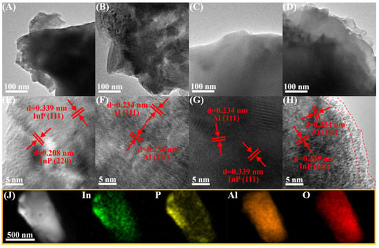
Figure 2.
TEM images of (A) InP, (B) Al substrate, (C) InP/Al, and (D) 0.6%Al2O3/InP/Al; HR-TEM images of (E) InP, (F) Al substrate, (G) InP/Al, and (H) 0.6%Al2O3/InP/Al; (J) EDX elemental mapping images of 0.6%Al2O3/InP/Al. The double lines indicated by the arrows represent a set of crystal planes.
2.3. UV-Vis-NIR Analysis
The optical properties of InP affected by Al and Al2O3 were analyzed by UV-vis-NIR diffuse reflectance spectra. Figure 3A shows the UV-vis-NIR diffuse reflectance spectra of InP, InP/Al, and 0.6%Al2O3/InP/Al. InP has a broad spectral response region and high absorption efficiency, making it an excellent light-harvesting material for solar energy conversion. For the InP/Al composite catalyst, the light absorption edge exhibits a blue shift, and absorption performance in 200–600 nm is significantly improved. The blue shift of InP/Al is caused by Al doping in InP during the synthesis of the In(OH)x/Al precursor. However, the enhanced absorption performance is attributed to Al reflecting photons that penetrate through InP, thereby improving light-harvesting efficiency. After loading Al2O3, the light absorption performance slightly decreases, which may be due to Al2O3 blocking the absorption of light, but the absorption edge of 0.6%Al2O3/InP/Al is close to InP/Al, indicating that Al2O3 coating has a weak impact on the light absorption region of InP/Al. The semiconductor bandgap can be derived by the following equation:
where α, ν, Eg, and A represent the absorption coefficient, optical frequency, bandgap energy, and constant, respectively [34,35]. In addition, the exponent n depends on the electronic transition type of the semiconductor, whether direct transitions (n = 1) or indirect transitions (n = 4). The interband electronic transition mode of InP is a direct transition, and the bandgap energies of InP, InP/Al, and 0.6%Al2O3/InP/Al are 1.27, 1.72, and 1.69 eV, respectively (Figure 3B). These results are consistent with the absorption spectra, and the minor changes in bandgap values between InP/Al and 0.6%Al2O3/InP/Al indicate a weak impact on the light absorption range of InP/Al when Al2O3 loading.
αhν = A (hν − Eg)n/2
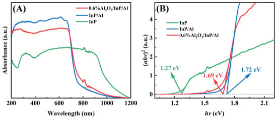
Figure 3.
(A)The UV-Vis-NIR diffuse reflectance spectra and (B) bandgap of InP, InP/Al, and 0.6%Al2O3/InP/Al.
2.4. XPS Analysis
The surface chemical states of the prepared samples were investigated using X-ray photoelectron spectroscopy (XPS), with all spectra calibrated against the C 1s peak (Figure S3). The survey spectra of Al substrate, InP, InP/Al, and 0.6%Al2O3/InP/Al confirm the existence of Al, In, P, and O in the 0.6%Al2O3/InP/Al catalyst, in agreement with EDS results (Figure 4A). Figure 4B shows the In 3d spectra of InP, InP/Al, and 0.6%Al2O3/InP/Al. The binding energy ranges of 442.5–447.5 eV and 450.0–455.0 eV are assigned to the In 3d5/2 and In 3d3/2 peaks, respectively. The In 3d spectra for all samples can be deconvoluted into two distinct components, corresponding to InP and InPO4. In the InP sample, the In 3d peaks at 444.2 eV (In 3d5/2) and 452.0 eV (In 3d3/2) are assigned to InP, while those at 445.2 eV (In 3d5/2) and 452.7 eV (In 3d3/2) are assigned to InPO4 [36,37]. The binding energies of InP and InPO4 species in the InP/Al sample are consistent with those in pure InP, but the InPO4 content in InP/Al increased. This increase is attributed to the partial oxidation of InP during phosphidation. With the Al2O3 loading onto InP/Al, the content of InPO4 on 0.6%Al2O3/InP/Al surface further increased, and the binding energies of both InP and InPO4 shifted towards higher binding energies by 0.3 eV, indicating successful loading of Al2O3 on the surface of InP/Al. Figure 4C presents the P 2p spectra of InP, InP/Al, and 0.6%Al2O3/InP/Al. In the bare InP, the characteristic peaks of P 2p3/2 and P 2p1/2 corresponding to P3− in InP emerged at 128.6 and 129.4 eV, respectively, while the peak at 133.2 eV belongs to P5+ in InPO4 [24,38,39,40]. The peak position of P3− in InP/Al did not change compared with InP. In contrast, the P5+ peak shifted towards high binding energy by ~1.1 eV, and the relative content significantly increased, indicating oxidation during phosphidation. After Al2O3 loading, the peaks of P3− and P5+ in 0.6%Al2O3/InP/Al shifted to higher binding energies by 0.1 eV, demonstrating electron transfer from the InP/Al to Al2O3. Figure 4D exhibits the Al 2p spectra of Al substrate, InP/Al, and 0.6%Al2O3/InP/Al. The Al 2p spectrum of the Al substrate exhibits two peaks at the binding energies of 71.8 eV and 74.5 eV, corresponding to the metallic state Al and surface Al2O3, respectively [30,31,41,42]. The metallic state Al and surface Al2O3 of InP/Al shift upward by 0.6 ± 0.1 eV compared to Al substrate, suggesting InP is deposited on metallic Al surfaces and charge transfer from Al to InP [41,43,44,45]. With Al2O3 coating, the binding energies of metallic Al and Al2O3 decreased by 0.2 eV, indicating that the Al2O3 passivation layer was successfully loaded onto the InP/Al surface. Figure S4 displays the O 1s spectra of InP, Al substrate, InP/Al, and 0.6%Al2O3/InP/Al. The binding energy at 531.7 eV in InP is attributed to the PO43− in InPO4, while the binding energy at 533.4 eV corresponds to the adsorbed O on the surface of InP [46,47,48]. In the Al sample, the O 1s characteristic peak is observed at 531.9 eV. The O 1s spectrum of InP/Al can be deconvoluted into three peaks of surface adsorbed O at 533.4 eV, lattice O in Al2O3 at 532.1 eV, and PO43− at 531.9 eV. After loading Al2O3 onto InP/Al, the O 1s peaks of Al2O3 and PO43− within 0.6%Al2O3/InP/Al shifted to lower binding energies by 0.1 eV, and the intensity of lattice O in Al2O3 increased compared to InP/Al, which was attributed to the Al2O3 loading.
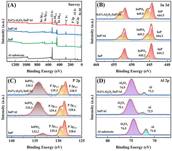
Figure 4.
XPS spectra of InP, Al substrate, InP/Al, and 0.6%Al2O3/InP/Al: (A) Survey, (B) In 3d, (C) P 2p, and (D) Al 2p.
2.5. Photocatalytic Hydrogen Production Performance
The photocatalytic HER performance of InP/Al was investigated under visible light irradiation in a reduced-pressure system. Figure S5 shows the HER activity of InP/Al photocatalysts at varied Cl (in InCl3) to NH3 (Cl:NH3) molar ratios. As the NH3 content increases, the activity initially rises, reaching a maximum at a Cl:NH3 molar ratio of 3:1, followed by a gradual decline. This trend is attributed to the reaction between protons (produced via In3+ hydrolysis in aqueous solution) and the Al substrate, which generates an interfacial buffer layer. This buffer layer reduces lattice mismatch between the Al substrate and the InP film, enhances carrier separation and transport, and thus improves photocatalytic efficiency [49]. Figure S6 displays the influence of NHP mass on the HER performance of InP/Al during phosphatizing. HER activity initially increases with NHP mass, peaking at an NHP:Al mass ratio of 4:1, which is due to optimized InP crystallite formation. Beyond this mass ratio, activity declines progressively. This decrease may arise from PH3 gas (generated by excess NHP) decomposing on InP surfaces to form passivating phosphorus-rich species, which inhibit charge transfer. Figure S7 illustrates the influence of the initial Al:In mass ratio on the photocatalytic HER performance of InP/Al. The HER rate initially increases with InP mass content but declines beyond a threshold, peaking at an Al:In mass ratio of 4:1. When the Al:In mass ratio is below 4:1, InP partially exposes the Al substrate. Conversely, excessive InP loading (ratios > 4:1) leads to insufficient light absorption and impaired photoexcited charge conductivity near the Al interface. Furthermore, the actual mass ratio of Al to In in InP/Al at the optimal HER activity was confirmed to be 8.1:1 (Figure S8). This discrepancy between the initial mass ratio and the final atomic composition is attributed to losses of indium during the phosphidation processes.
Comparative experiments were conducted to confirm the function of an Al substrate and an Al2O3 protection layer in the 0.6%Al2O3/InP/Al photocatalyst. As displayed in Figure 5A, Bare InP shows negligible hydrogen production, due to significant electron-hole recombination loss and critical corrosion of the InP. After supporting InP on the Al substrate, the HER activity of InP/Al composite significantly improved, 7.3-fold higher than that of bare InP. But severe corrosion of InP/Al remains. Similarly, the HER activity of InP increased threefold after loading with Al2O3, indicating that corrosion of InP can be suppressed by coating with Al2O3. By integrating these advantages, the 0.6%Al2O3/InP/Al photocatalyst presents the highest HER performance of 145.64 μmol·g−1·h−1, a 19.57-fold enhancement compared with the pristine InP catalyst. These results indicate that charge separation and corrosion resistance were significantly improved by combining InP with the Al substrate and a coated Al2O3 protection layer. We further optimized the Al2O3 loading content, and the results are shown in Figure 5B. As the Al2O3 loading increased, the photocatalytic activity of Al2O3/InP/Al improved, reaching an optimum at 0.6 wt% loading. Beyond this threshold, further increases in Al2O3 loading led to a decline in HER activity. This decline may stem from attenuation of light absorption by InP due to the thicker Al2O3 layer (Figure S9), thereby reducing the concentration of photoexcited carriers within the catalyst. Figure 5C compares the stability of InP/Al and 0.6%Al2O3/InP/Al catalysts in a long-term hydrogen production test. Notably, the HER activity of InP/Al declines sharply with cycling, indicating severe photocorrosion. By comparison, the 0.6%Al2O3/InP/Al sample operated for 10 h without significant decay, demonstrating higher efficiency and superior stability. The enhanced performance originates from the Al2O3 protective layer, which simultaneously accelerates the transfer of photoinduced electrons and inhibits InP degradation by isolating the catalyst from direct water contact, thereby significantly improving the stability and HER performance. The morphology and structure analysis after reaction also confirm the stability of the 0.6%Al2O3/InP/Al photocatalyst (Figures S10 and S11). In addition, the HER performance of the 0.6%Al2O3/InP/Al photocatalyst was compared under reduced-pressure and atmospheric pressure systems (Figure S12). The 0.6%Al2O3/InP/Al photocatalyst exhibits higher HER activity under reduced pressure than under atmospheric pressure conditions. This enhancement arises because reduced pressure removes newly generated O2 during the reaction, prevents oxygen-induced photocorrosion, and suppresses H2–O2 recombination on the catalyst surface (Figure 5D).
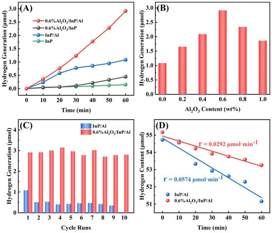
Figure 5.
(A) The hydrogen production performance of InP, InP/Al, 0.6%Al2O3/InP and 0.6%Al2O3/InP/Al, (B) the photocatalytic hydrogen production of Al2O3/InP/Al at different Al2O3 loading content (calculated based on Al content), (C) the hydrogen production stability of InP/Al and 0.6%Al2O3/InP/Al, and (D) the H2–O2 recombination reaction of InP/Al and 0.6%Al2O3/InP/Al.
2.6. Isotope Tracing Experiment and AQE Analysis
To identify the productions obtained from photocatalytic water splitting, isotope tracing experiments were performed over 0.6%Al2O3/InP/Al photocatalyst under visible light irradiation. The observed signal at mass-to-charge ratio (m/z) of 4 is attributed to D2 generated by the photocatalytic splitting of D2O (Figure 6A). Similarly, the signal at m/z = 36 in Figure 6B confirms that 18O2 originates from photocatalytic decomposition of H218O over the 0.6%Al2O3/InP/Al catalyst, demonstrating its oxygen evolution activity. These results collectively verify that visible-light-driven overall water splitting produces H2 and O2 on a 0.6%Al2O3/InP/Al photocatalyst. Figure S13 presents the AQE for overall water splitting over the 0.6%Al2O3/InP/Al catalyst across wavelengths from 500 to 750 nm. The AQE decreases with increasing wavelength, exhibiting strong wavelength dependence. A maximum AQE of 0.97% is observed at 500 nm, while the AQE at 750 nm remains 0.45%, suggesting significant photocatalytic activity in the visible light region. Additionally, Table S1 lists the AQE at 500 nm for the POWS reaction is comparable to those reported in recent studies for similar heterostructures, highlighting the competitiveness of our catalyst system.
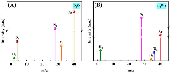
Figure 6.
MS spectra of visible light photocatalytic decomposition of (A) D2O and (B) H218O over 0.6%Al2O3/InP/Al catalyst.
2.7. Electrochemical Analysis
The photocatalytic HER performance and photoinduced carrier separation efficiency were evaluated using an electrochemical method. Figure 7A exhibits the transient photocurrent response of InP/Al and 0.6%Al2O3/InP/Al under visible light pulse irradiation. InP/Al exhibits a lower photocurrent density and decreases significantly with extended irradiation time, implying photocorrosion of the catalyst. In contrast, 0.6%Al2O3/InP/Al exhibits a higher photocurrent density, about four times higher than InP/Al, indicating that the Al2O3 passivation layer enhances charge separation, prolongs carrier lifetime, and significantly improves stability [27,50]. Subsequently, electrochemical impedance spectroscopy (EIS) was applied to analyze the charge transfer properties of photoexcited carriers in photocatalysts. Figure 7B displays the EIS spectra of the as-prepared catalysts related to charge transfer at high-frequency regions. The large EIS semicircle diameter of InP/Al indicates high charge transfer resistance. The resistance of carrier transfer in 0.6%Al2O3/InP/Al is significantly reduced compared to InP/Al, indicating that the charge transfer rate can be remarkably enhanced by coating Al2O3 layers [51,52]. The hydrogen and oxygen evolution performance of InP/Al and 0.6%Al2O3/InP/Al was analyzed using linear sweep voltammetry. Figure 7C presents the cathodic polarization curves of InP/Al and 0.6%Al2O3/InP/Al catalysts, and the cathodic current densities observed in the range of −0.2 to −1.0 V (vs. Ag/AgCl) correspond to the generation of H2. 0.6%Al2O3/InP/Al catalyst presents an enhanced HER current density and a lower overpotential than InP/Al [53,54]. The anodic polarization curve of the catalysts is shown in Figure 7D, and the observed anodic current densities in the range of 1.0–1.2 V (vs. Ag/AgCl) correspond to the generation of O2. Compared with InP/Al, the oxygen evolution overpotential of 0.6%Al2O3/InP/Al catalyst is reduced, and the oxygen evolution current density is improved [55,56]. The above results indicate that 0.6%Al2O3/InP/Al is an excellent photocatalyst for overall water splitting. Furthermore, we investigated the charge carrier separation and transport properties of 0.6%Al2O3/InP/Al prepared at Cl (in InCl3) to NH3 molar ratios of 1:1 and 3:1, and the results are shown in Figures S14 and S15. The higher photocurrent density and smaller EIS semicircle diameter observed for the 0.6%Al2O3/InP/Al prepared at Cl:NH3 = 3:1 indicate significantly enhanced carrier separation and transfer efficiency. This improvement is attributed to a buffer layer formed between the Al substrate and InP, which reduces their lattice mismatch, thereby contributing to the photocatalytic water-splitting performance.
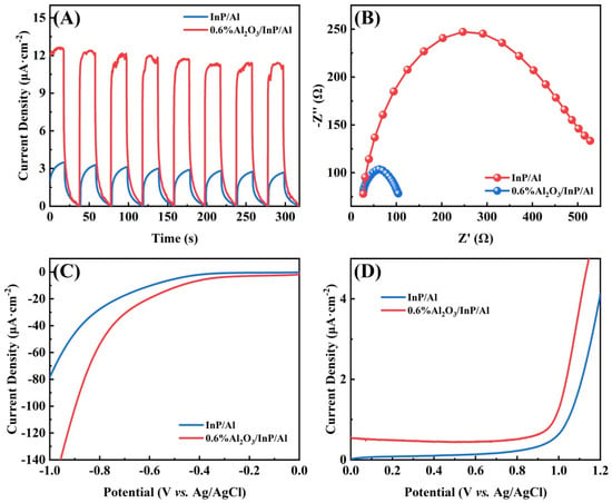
Figure 7.
(A) Transient photocurrent responses, (B) electrochemical impedance spectroscopy Nyquist plots, (C) cathodic polarization curve, and (D) anodic polarization curve of InP/Al and 0.6%Al2O3/InP/Al.
2.8. Photoluminescence Spectra Analysis
To further analyze the carrier separation and recombination efficiency of the catalysts, photoluminescence (PL) spectroscopy was performed. Figure 8 shows the PL emission spectra of InP, InP/Al, and 0.6%Al2O3/InP/Al with an excitation wavelength of 600 nm at room temperature. InP displayed the highest intensity of PL signal, indicating rapid recombination of photoinduced carriers. The PL intensity of InP, InP/Al, and 0.6%Al2O3/InP/Al decreased gradually, while the 0.6%Al2O3/InP/Al catalyst exhibited the lowest fluorescence intensity. The fluorescence intensity decreased significantly after the combination of InP and Al, which is attributed to the formation of a metal-semiconductor junction between InP and Al that effectively facilitates charge carrier separation [31,44]. Upon loading Al2O3 onto the InP/Al surface, the fluorescence intensity further decreased, due to the thin Al2O3 layer passivating the InP/Al interface, effectively reducing surface defects and thus suppressing surface recombination [57,58]. The corresponding average fluorescence lifetimes of InP, InP/Al, and 0.6%Al2O3/InP/Al are listed in Table 1. The fluorescence lifetimes of InP, InP/Al, and 0.6%Al2O3/InP/Al increased successively, indicating that the migration of carriers as well as electron-hole separation are enhanced by the Al substrate and Al2O3 thin layers. These results demonstrate that the composite of Al and Al2O3 can promote the separation and transfer of photoinduced carriers [51,59], whereas Al primarily enhances carrier separation, and Al2O3 suppresses the corrosion of InP, thereby achieving efficient photocatalytic water-splitting performance.
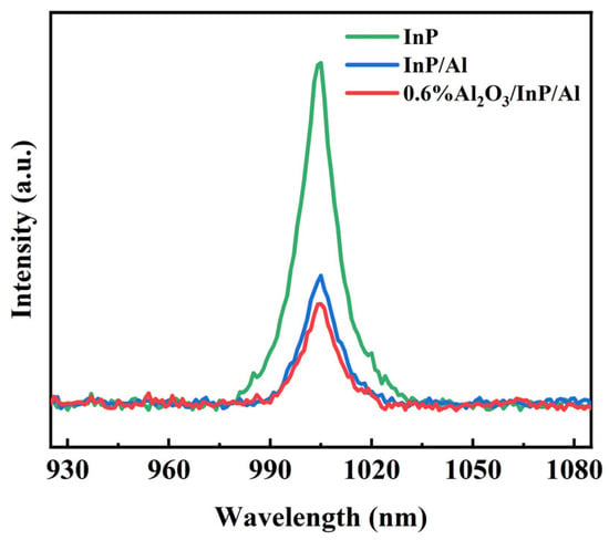
Figure 8.
PL spectra of InP, InP/Al, and 0.6%Al2O3/InP/Al catalysts excited at 600 nm.

Table 1.
Fluorescence lifetimes of InP, InP/Al, and 0.6%Al2O3/InP/Al composite.
2.9. Mechanism Analysis
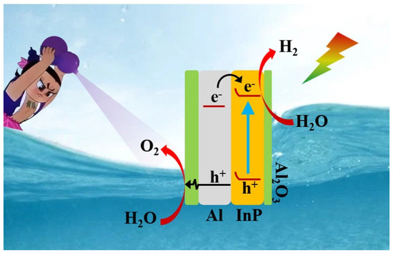
The experimental results and characterization data form the basis for the proposed PWOS mechanism on the Al2O3/InP/Al catalyst, which is depicted in Scheme 1. Under visible light irradiation, electrons within the Al substrate are transferred to the conduction band of InP and participate in the reaction of water reduction to generate H2 [60]. The holes generated in the valence band of InP are transferred to the Al surface, followed by tunneling through a thin layer of Al2O3 or transferring to the surface through the abundant Al3+ cation vacancy network in the Al2O3 for water oxidation to generate O2 [27,61]. The Schottky barrier at the interface between InP and Al promotes the separation of InP photoexcited carriers and prolongs the photoexcited carrier lifetime. Simultaneously, the thin Al2O3 layer protects InP/Al from photocorrosion and reduces defect-induced surface recombination. Finally, the dissolved oxygen in water was expelled from the reactor using a reduced-pressure system. Consequently, Al2O3/InP/Al can realize POWS with excellent performance.
Scheme 1.
Mechanism of POWS over Al2O3/InP/Al using a reduced-pressure system under visible illumination.
3. Materials and Methods
3.1. Materials
This study used aluminum powder (Al, >99%, Shanghai Aladdin Biochemical Technology Co., Ltd., Shanghai, China) as a substrate. Indium chloride (InCl3, >99.99%, Shanghai Aladdin Biochemical Technology Co., Ltd., Shanghai, China), aluminum chloride (AlCl3, >99%, Shanghai Aladdin Biochemical Technology Co., Ltd., Shanghai, China), sodium hypophosphite (NaH2PO2, abbreviated as NHP, >99.5%, Shanghai Macklin Biochemical Co., Ltd., Shanghai, China), and ammonia solution (NH3·H2O, 28–30 wt%, Shanghai Macklin Biochemical Co., Ltd., Shanghai, China) were used as the indium, aluminum, phosphorus, and alkali sources, respectively. Commercial indium phosphide (InP, 99.998%, Shanghai Macklin Biochemical Co., Ltd., Shanghai, China) was used as a reference material for comparison. All reagents were used without further purification.
3.2. Preparation of Photocatalysts
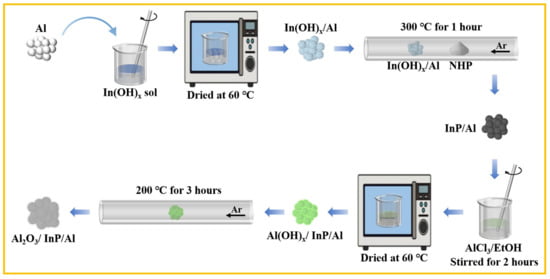
The synthesis of the Al2O3/InP/Al photocatalyst is shown in Scheme 2, while detailed experimental procedures are described below.
Scheme 2.
Process diagram for preparing Al2O3/InP/Al photocatalysts.
3.2.1. Preparation of InP/Al Sample
Firstly, the In(OH)x sol was prepared by adjusting the molar ratios between Cl (in InCl3) and NH3. The In(OH)x sol and Al substrate were mixed at specific Al:In mass ratios, and the mixture was dried at 60 °C to produce In(OH)x/Al precursor. NHP and the In(OH)x/Al precursor (at designated mass ratios) were positioned upstream and downstream of the inlet in a quartz tube furnace, respectively. After rinsing the tube furnace with argon gas flow (50 mL·min−1) to exclude air, the temperature was raised to 300 °C at a rate of 2 °C·min−1 and maintained at a constant temperature for 1 h to obtain InP/Al. The sample was collected after being cooled to room temperature for future utilization.
3.2.2. Preparation of Al2O3/InP/Al Sample
To prepare the Al2O3/InP/Al photocatalyst, AlCl3 corresponding to 0.2 wt% Al2O3 (calculated based on Al content) was dissolved in 10 mL of anhydrous ethanol, and then 50 mg of InP/Al was added. The solution was continuously stirred at room temperature for 2 h and then dried at 60 °C. Subsequently, the dried sample was heated to 200 °C at a rate of 5 °C·min−1 in an argon gas flow and kept at a constant temperature for 3 h. Al2O3/InP/Al photocatalysts with Al2O3 loadings of 0.4 wt%, 0.6 wt%, 0.8 wt%, and 1.0 wt% were prepared using the same method.
3.3. Photocatalytic H2 Evolution Experiments
All photocatalytic hydrogen production experiments were carried out under a reduced-pressure system. The detailed procedure is as follows: 20 mg of the catalyst was evenly dispersed on the bottom of a 140 mL sealed reactor containing 50 mL deionized water, which was equipped with a flat quartz window. The system was purged with high-purity argon (15 mL·min−1), and the evolved gases were collected by a collection tube with a silicone seal. The total volume of mixed gas was quantified via water displacement. The Xenon lamp light source (incident light power: 200 mW·cm−1, Beijing NBET Technology Co., Ltd., Beijing, China) was equipped with a 420 nm cut-off filter. Gas chromatography (Agilent 6820, TCD, 13X Column, Ar carrier gas, Agilent Technologies (Shanghai) Co., Ltd., Shanghai, China) was employed for qualitative and quantitative analysis of the gas mixture in the collection tube during the water-splitting process. The stability experiment for photocatalytic hydrogen evolution was carried out as follows. After the first photocatalytic reaction under visible light irradiation, the collection tube was filled with water again without further treatment of the photocatalyst. Subsequently, the mixed gas was recollected to fill the tube, and this procedure was repeated for each cycle.
Under the same photocatalytic reaction conditions, monochromatic light was obtained using a bandpass filter (center wavelengths: 500, 550, 600, 650, 700, and 750 nm) for the AQE measurement of the catalyst. The number of incident photons was determined using a radiometer with a silicon photodetector (FU 100). The reactor was irradiated with monochromatic light for 1 h, and the hydrogen yield was quantified via gas chromatography. The AQE was calculated using the following equation:
4. Conclusions
The synthesized Al2O3/InP/Al composite photocatalyst demonstrated excellent photocatalytic activity and remarkable stability for PWOS. The Al2O3 protective layer on the surface of InP could rapidly transfer photogenerated holes and protect InP from photocorrosion. As a light reflection layer, the electron-rich Al can effectively separate photoinduced carriers and enhance the light absorption performance of InP. Furthermore, to achieve the POWS and long-term stability, the reaction system was maintained under reduced pressure to remove dissolved oxygen. This effectively suppressed the H2–O2 recombination reverse reaction and minimized photocorrosion of InP. Thus, the Al2O3/InP/Al photocatalyst can achieve efficient and stable POWS under visible light illumination. This work provides a viable strategy for designing and manufacturing efficient and durable InP-based photocatalysts for solar-driven green hydrogen production.
Supplementary Materials
The following supporting information can be downloaded at https://www.mdpi.com/article/10.3390/molecules30183822/s1, Figure S1: XRD patterns of Al substrate and corresponding JCPDS card; Figure S2: XRD patterns of InP and corresponding JCPDS card; Figure S3: XPS C 1s spectra of InP, Al substrate, InP/Al, and 0.6%Al2O3/InP/Al; Figure S4: XPS O 1s spectra of InP, Al substrate, InP/Al, and 0.6%Al2O3/InP/Al; Figure S5: The photocatalytic hydrogen production of InP/Al prepared by adjusting the molar ratios between Cl (in InCl3) and NH3; Figure S6: The photocatalytic hydrogen production of InP/Al is affected by NHP:Al mass ratio; Figure S7: The photocatalytic hydrogen production of InP/Al is affected by Al:In mass ratio; Figure S8: The content of Al and In in InP/Al; Figure S9: (A) TEM and (B) HRTEM images of 1.0%Al2O3/InP/Al photocatalyst; Figure S10: (A) TEM and (B) HRTEM images of 0.6%Al2O3/InP/Al photocatalyst after 10 h of photocatalytic reaction; Figure S11: XRD patterns of 0.6%Al2O3/InP/Al photocatalyst after 10 h of photocatalytic reaction; Figure S12: The photocatalytic hydrogen production activity under reduced pressure over 0.6%Al2O3/InP/Al photocatalyst; Figure S13: The AQE of 0.6%Al2O3/InP/Al catalyst at different wavelengths; Figure S14: The transient photocurrent response of 0.6%Al2O3/InP/Al with varying Cl (in InCl3) to NH3 molar ratios (1:1 and 3:1); Figure S15: The EIS spectra of 0.6%Al2O3/InP/Al with varying Cl (in InCl3) to NH3 molar ratios (1:1 and 3:1). Table S1: The AQEs of hydrogen production using In-based and Al-based photocatalysts. References [27,62,63,64,65,66,67] are cited in the supplementary materials.
Author Contributions
Conceptualization, Z.Y. and G.L.; methodology, Z.Y.; software, Z.Y.; validation, W.Z., X.N. and Z.H.; formal analysis, Z.Y.; investigation, W.Z., X.N. and Z.H.; resources, G.L.; data curation, Z.Y.; writing—original draft preparation, Z.Y.; writing—review and editing, W.Z. and G.L.; visualization, Z.Y.; supervision, G.L.; project administration, G.L.; funding acquisition, G.L. All authors have read and agreed to the published version of the manuscript.
Funding
This research was funded by the National Key Research and Development Program of China (No. 2022YFB3803600), the National Natural Science Foundation of China (No. 22272189, and 22302212), the Gansu Youth Science and Technology Foundation (No. 24JRRA057), Chinese Academy of Sciences Talent Program youth Project B (E40149YB), and LICP Special Talent Program (E101A7SY).
Institutional Review Board Statement
Not applicable.
Informed Consent Statement
Not applicable.
Data Availability Statement
Data are contained within the article and Supplementary Materials.
Conflicts of Interest
The authors declare no conflicts of interest.
References
- Ahmed, S.; Khan, M.K.; Kim, J. Revolutionary advancements in carbon dioxide valorization via metal-organic framework-based strategies. Carbon Capture Sci. Technol. 2025, 15, 100405. [Google Scholar] [CrossRef]
- Sohail, M.; Rauf, S.; Irfan, M.; Hayat, A.; Alghamdi, M.M.; El-Zahhar, A.A.; Ghernaout, D.; Al-Hadeethi, Y.; Lv, W. Recent developments, advances and strategies in heterogeneous photocatalysts for water splitting. Nanoscale Adv. 2024, 6, 1286–1330. [Google Scholar] [CrossRef]
- Riera, J.A.; Lima, R.M.; Knio, O.M. A review of hydrogen production and supply chain modeling and optimization. Int. J. Hydrogen Energy 2023, 48, 13731–13755. [Google Scholar] [CrossRef]
- Zhou, J.; Tian, Y.; Gu, H.; Jiang, B. Photocatalytic hydrogen evolution: Recent advances in materials, modifications, and photothermal synergy. Int. J. Hydrogen Energy 2025, 115, 113–130. [Google Scholar] [CrossRef]
- Lin, Z.; Saito, H.; Sato, H.; Sugimoto, T. Positive and Negative Impacts of Interfacial Hydrogen Bonds on Photocatalytic Hydrogen Evolution. J. Am. Chem. Soc. 2024, 146, 22276–22283. [Google Scholar] [CrossRef]
- Jana, B.; Reva, Y.; Scharl, T.; Strauss, V.; Cadranel, A.; Guldi, D.M. Carbon Nanodots for All-in-One Photocatalytic Hydrogen Generation. J. Am. Chem. Soc. 2021, 143, 20122–20132. [Google Scholar] [CrossRef] [PubMed]
- Fujishima, A.; Honda, K. Electrochemical Photolysis of Water at a Semiconductor Electrode. Nature 1972, 238, 37–38. [Google Scholar] [CrossRef] [PubMed]
- Rahman, M.Z.; Gascon, J. Is photocatalytic hydrogen production closer to application? Chem Catal. 2023, 3, 100536. [Google Scholar] [CrossRef]
- Takata, T.; Jiang, J.; Sakata, Y.; Nakabayashi, M.; Shibata, N.; Nandal, V.; Seki, K.; Hisatomi, T.; Domen, K. Photocatalytic water splitting with a quantum efficiency of almost unity. Nature 2020, 581, 411–414. [Google Scholar] [CrossRef]
- Suzuki, T.M.; Saeki, S.; Sekizawa, K.; Kitazumi, K.; Takahashi, N.; Morikawa, T. Photoelectrochemical hydrogen production by water splitting over dual-functionally modified oxide: P-Type N-doped Ta2O5 photocathode active under visible light irradiation. Appl. Catal. B 2017, 202, 597–604. [Google Scholar] [CrossRef]
- Impemba, S.; Provinciali, G.; Filippi, J.; Salvatici, C.; Berretti, E.; Caporali, S.; Banchelli, M.; Caporali, M. Engineering the heterojunction between TiO2 and In2O3 for improving the solar-driven hydrogen production. Int. J. Hydrogen Energy 2024, 63, 896–904. [Google Scholar] [CrossRef]
- Edalati, K.; Fujita, I.; Takechi, S.; Nakashima, Y.; Kumano, K.; Razavi-Khosroshahi, H.; Arita, M.; Watanabe, M.; Sauvage, X.; Akbay, T.; et al. Photocatalytic activity of aluminum oxide by oxygen vacancy generation using high-pressure torsion straining. Scr. Mater. 2019, 173, 120–124. [Google Scholar] [CrossRef]
- Liu, E.; Chen, J.; Ma, Y.; Feng, J.; Jia, J.; Fan, J.; Hu, X. Fabrication of 2D SnS2/g-C3N4 heterojunction with enhanced H2 evolution during photocatalytic water splitting. J. Colloid Interface Sci. 2018, 524, 313–324. [Google Scholar] [CrossRef] [PubMed]
- Nan, H.; Wu, W.; Feng, K.; Shan, B.; Qiu, Y.; Zhang, Y. Improved photocatalytic efficiency and stability of CdS/ZnO shell/core nanoarrays with high coverage and enhanced interface combination. Int. J. Hydrogen Energy 2017, 42, 848–857. [Google Scholar] [CrossRef]
- Wang, Z.; Su, B.; Xu, J.; Hou, Y.; Ding, Z. Direct Z-scheme ZnIn2S4/LaNiO3 nanohybrid with enhanced photocatalytic performance for H2 evolution. Int. J. Hydrogen Energy 2020, 45, 4113–4121. [Google Scholar] [CrossRef]
- Yang, L.; Liu, J.; Yang, L.; Zhang, M.; Zhu, H.; Wang, F.; Yin, J. Co3O4 imbedded g-C3N4 heterojunction photocatalysts for visible-light-driven hydrogen evolution. Renew. Energy 2020, 145, 691–698. [Google Scholar] [CrossRef]
- Deng, C.; Zhu, J.; Huang, Y. Performance of nanoparticle-enhanced thin-film solar cell with near-perfect absorption. Phys. B 2024, 685, 416032. [Google Scholar] [CrossRef]
- Li, Q.; Zheng, M.; Zhong, M.; Ma, L.; Wang, F.; Ma, L.; Shen, W. Engineering MoSx/Ti/InP Hybrid Photocathode for Improved Solar Hydrogen Production. Sci. Rep. 2016, 6, 29738. [Google Scholar] [CrossRef]
- Jo, J.-H.; Jo, D.-Y.; Choi, S.-W.; Lee, S.-H.; Kim, H.-M.; Yoon, S.-Y.; Kim, Y.; Han, J.-N.; Yang, H. Highly Bright, Narrow Emissivity of InP Quantum Dots Synthesized by Aminophosphine: Effects of Double Shelling Scheme and Ga Treatment. Adv. Opt. Mater. 2021, 9, 2100427. [Google Scholar] [CrossRef]
- Yang, S.; Zhao, P.; Zhao, X.; Qu, L.; Lai, X. InP and Sn:InP based quantum dot sensitized solar cells. J. Mater. Chem. A 2015, 3, 21922–21929. [Google Scholar] [CrossRef]
- Dursap, T.; Fadel, M.; Regreny, P.; Tapia Garcia, C.; Chevalier, C.; Nguyen, H.S.; Drouard, E.; Brottet, S.; Gendry, M.; Danescu, A.; et al. Enhanced Light Trapping in GaAs/TiO2-Based Photocathodes for Hydrogen Production. ACS Appl. Mater. Interfaces 2023, 15, 53446–53454. [Google Scholar] [CrossRef] [PubMed]
- Rana, P.; Soni, V.; Kumar, R.; Sonu; Chawla, A.; Parwaz Khan, A.A.; Singh, P.; Thakur, S.; Raizada, P.; Alzahrani, K.A. Advances in photocatalytic hydrogen production with ZnO/ZnS-Based nanostructured materials. Fuel 2025, 386, 134286. [Google Scholar] [CrossRef]
- Chen, Z.; Cheng, C.; Xing, F.; Huang, C. Strong interfacial coupling for NiS thin layer covered CdS nanorods with highly efficient photocatalytic hydrogen production. New J. Chem. 2020, 44, 19083–19090. [Google Scholar] [CrossRef]
- Kim, H.; Kim, Y.; Choi, B.J. Interfacial characteristics of Au/Al2O3/InP metal-insulator-semiconductor diodes. AIP Adv. 2018, 8, 095022. [Google Scholar] [CrossRef]
- He, G.; Gao, J.; Chen, H.; Cui, J.; Sun, Z.; Chen, X. Modulating the Interface Quality and Electrical Properties of HfTiO/InGaAs Gate Stack by Atomic-Layer-Deposition-Derived Al2O3 Passivation Layer. ACS Appl. Mater. Interfaces 2014, 6, 22013–22025. [Google Scholar] [CrossRef]
- Lu, H.-L.; Sun, L.; Ding, S.-J.; Xu, M.; Zhang, D.W.; Wang, L.-K. Characterization of atomic-layer-deposited Al2O3/GaAs interface improved by NH3 plasma pretreatment. Appl. Phys. Lett. 2006, 89, 152910. [Google Scholar] [CrossRef]
- Ning, X.; Zhen, W.; Wu, Y.; Lu, G. Inhibition of CdS photocorrosion by Al2O3 shell for highly stable photocatalytic overall water splitting under visible light irradiation. Appl. Catal. B 2018, 226, 373–383. [Google Scholar] [CrossRef]
- Willis, D.E.; Taheri, M.M.; Kizilkaya, O.; Leite, T.R.; Zhang, L.; Ofoegbuna, T.; Ding, K.; Dorman, J.A.; Baxter, J.B.; McPeak, K.M. Critical Coupling of Visible Light Extends Hot-Electron Lifetimes for H2O2 Synthesis. ACS Appl. Mater. Interfaces 2020, 12, 22778–22788. [Google Scholar] [CrossRef]
- Gao, W.; Liu, Q.; Zhang, S.; Yang, Y.; Zhang, X.; Zhao, H.; Qin, W.; Zhou, W.; Wang, X.; Liu, H.; et al. Electromagnetic induction derived micro-electric potential in metal-semiconductor core-shell hybrid nanostructure enhancing charge separation for high performance photocatalysis. Nano Energy 2020, 71, 104624. [Google Scholar] [CrossRef]
- Bayles, A.; Tian, S.; Zhou, J.; Yuan, L.; Yuan, Y.; Jacobson, C.R.; Farr, C.; Zhang, M.; Swearer, D.F.; Solti, D.; et al. Al@TiO2 Core–Shell Nanoparticles for Plasmonic Photocatalysis. ACS Nano 2022, 16, 5839–5850. [Google Scholar] [CrossRef]
- Zhang, T.; Xu, M.; Li, J. Enhanced photocatalysis of TiO2 by aluminum plasmonic. Catal. Today 2021, 376, 162–167. [Google Scholar] [CrossRef]
- Ma, H.; Wei, Q.; Chen, W.; Li, Q. Corrosion shielding effect of polyaluminium sulphate on metallic aluminium during the solidification of radioactive incineration bottom ash by low alkalinity cement. Constr. Build. Mater. 2024, 447, 137970. [Google Scholar] [CrossRef]
- Zhang, C.; Chen, X.; Liu, Y.; Zhao, Y.; Zhang, H.; Chen, D.; Zong, S.; Wang, J. Synthesis of InP quantum dot decorated Bi2WO6 microspheres for the efficient photocatalytic production of hydrogen peroxide in water. J. Alloys Compd. 2025, 1011, 178253. [Google Scholar] [CrossRef]
- Fazal, T.; Ismail, B.; Khan, A.; Khan, I.; Shah, M.; Bahadur, A.; Iqbal, S.; Mahmood, S.; Alam, S.; Ali, F.; et al. Synthesis and Characterization of Undoped and Strontium-Doped Zinc Ferrites for Applications of Solid Oxide Fuel Cells and Photocatalytic Hydrogen Generation. Luminescence 2025, 40, e70210. [Google Scholar] [CrossRef]
- Mittal, H.; Kumar, A.; Sharma, D.; Khanuja, M. Z-Scheme Enabled 1D/2D Nanocomposite of ZnO Nanorods and Functionalized g-C3N4 Nanosheets for Sustainable Degradation of Terephthalic Acid. ChemSusChem 2025, 18, e202401408. [Google Scholar] [CrossRef]
- Pan, J.S.; Tay, S.T.; Huan, C.H.A.; Wee, A.T.S. XPS study of incident angle effects on the ion beam modification of InP surfaces by 6 keV O2+. Surf. Interface Anal. 1999, 27, 993–997. [Google Scholar] [CrossRef]
- Gonçalves, A.-M.; Mézailles, N.; Mathieu, C.; Le Floch, P.; Etcheberry, A. Fully Protective yet Functionalizable Monolayer on InP. Chem. Mater. 2010, 22, 3114–3120. [Google Scholar] [CrossRef]
- Quinlan, K.P.; Yip, P.W.; Rai, A.K.; Wittberg, T.N. Oxidation of n-InP and Indium in the Negative Potential Region at pH 5. J. Electrochem. Soc. 1996, 143, 524. [Google Scholar] [CrossRef]
- Nguyen, Q.H.; So, S.; Nguyen, Q.H.; Kim, I.T.; Hur, J. Mechanochemical synthesis of InP nanoparticles embedded in hybrid conductive matrix for high-performance lithium-ion batteries. Chem. Eng. J. 2020, 399, 125826. [Google Scholar] [CrossRef]
- Huang, K.; Demadrille, R.; Silly, M.G.; Sirotti, F.; Reiss, P.; Renault, O. Internal Structure of InP/ZnS Nanocrystals Unraveled by High-Resolution Soft X-ray Photoelectron Spectroscopy. ACS Nano 2010, 4, 4799–4805. [Google Scholar] [CrossRef]
- Ghori, M.Z.; Veziroglu, S.; Hinz, A.; Shurtleff, B.B.; Polonskyi, O.; Strunskus, T.; Adam, J.; Faupel, F.; Aktas, O.C. Role of UV Plasmonics in the Photocatalytic Performance of TiO2 Decorated with Aluminum Nanoparticles. ACS Appl. Nano Mater. 2018, 1, 3760–3764. [Google Scholar] [CrossRef]
- Chen, S.-Z.; Zhang, P.-Y.; Zhu, W.-P.; Chen, L.; Xu, S.-M. Deactivation of TiO2 photocatalytic films loaded on aluminium: XPS and AFM analyses. Appl. Surf. Sci. 2006, 252, 7532–7538. [Google Scholar] [CrossRef]
- Lin, J.-H.; Patil, R.A.; Devan, R.S.; Liu, Z.-A.; Wang, Y.-P.; Ho, C.-H.; Liou, Y.; Ma, Y.-R. Photoluminescence mechanisms of metallic Zn nanospheres, semiconducting ZnO nanoballoons and metal-semiconductor Zn/ZnO nanospheres. Sci. Rep. 2014, 4, 6967. [Google Scholar] [CrossRef]
- Lin, Z.; Wang, X.; Liu, J.; Tian, Z.; Dai, L.; He, B.; Han, C.; Wu, Y.; Zeng, Z.; Hu, Z. On the role of localized surface plasmon resonance in UV-Vis light irradiated Au/TiO2 photocatalysis systems: Pros and cons. Nanoscale 2015, 7, 4114–4123. [Google Scholar] [CrossRef]
- Zhang, Z.; Li, M.; Wang, H. ZIF-8 Derived ZnO Decorated with Polydopamine and Au Nanoparticles for Efficient Photocatalytic Degradation of Rhodamine B. ChemistrySelect 2021, 6, 5356–5365. [Google Scholar] [CrossRef]
- Galatage, R.V.; Dong, H.; Zhernokletov, D.M.; Brennan, B.; Hinkle, C.L.; Wallace, R.M.; Vogel, E.M. Electrical and chemical characteristics of Al2O3/InP metal-oxide-semiconductor capacitors. Appl. Phys. Lett. 2013, 102, 132903. [Google Scholar] [CrossRef]
- Besland, M.P.; Jourba, S.; Lambrinos, M.; Louis, P.; Viktorovitch, P.; Hollinger, G. Optimized SiO2/InP structures prepared by electron cyclotron resonance plasma. J. Appl. Phys. 1996, 80, 3100–3109. [Google Scholar] [CrossRef]
- Virieux, H.; Le Troedec, M.; Cros-Gagneux, A.; Ojo, W.-S.; Delpech, F.; Nayral, C.; Martinez, H.; Chaudret, B. InP/ZnS Nanocrystals: Coupling NMR and XPS for Fine Surface and Interface Description. J. Am. Chem. Soc. 2012, 134, 19701–19708. [Google Scholar] [CrossRef]
- Geisz, J.F.; France, R.M.; Schulte, K.L.; Steiner, M.A.; Norman, A.G.; Guthrey, H.L.; Young, M.R.; Song, T.; Moriarty, T. Six-junction III–V solar cells with 47.1% conversion efficiency under 143 Suns concentration. Nat. Energy 2020, 5, 326–335. [Google Scholar] [CrossRef]
- Feng, Y.; Fang, X.; Zang, J.; Song, B.; Hu, C.; Dong, X.; Ding, Y. Improvement of charge-transfer kinetics via MXene and cobalt containing polyoxometalate loading on CdS for photocatalytic hydrogen production. Sci. China Chem. 2025, 68, 772–780. [Google Scholar] [CrossRef]
- Zhao, Z.; Han, H.; Dong, J.; Zhou, J.; Shu, Z. Simultaneously optimizing optical response and exciton dissociation of amino-rich red poly(heptazine imide) nanoparticles with tunable n–π* electronic transition for improved photocatalytic hydrogen evolution. Sep. Purif. Technol. 2025, 361, 131331. [Google Scholar] [CrossRef]
- Zhou, S.; Yang, C.; Guo, L.; Ali Soomro, R.; Niu, M.; Yang, Z.; Du, R.; Wang, D.; Fu, F.; Xu, B. Synergism of electronic structure regulation and interface engineering for boosting hydrogen evolution reaction on S-Scheme FeS2/S-ZnSnO3 heterostructure. Appl. Surf. Sci. 2023, 625, 157192. [Google Scholar] [CrossRef]
- Liu, G.; Narangari, P.R.; Trinh, Q.T.; Tu, W.; Kraft, M.; Tan, H.H.; Jagadish, C.; Choksi, T.S.; Ager, J.W.; Karuturi, S.; et al. Manipulating Intermediates at the Au–TiO2 Interface over InP Nanopillar Array for Photoelectrochemical CO2 Reduction. ACS Catal. 2021, 11, 11416–11428. [Google Scholar] [CrossRef]
- Jia, M.; Lu, G. 750 nm visible light-driven overall water splitting to H2 and O2 over Boron-doped Zn3As2 photocatalyst. Appl. Catal. B 2023, 338, 123045. [Google Scholar] [CrossRef]
- Liu, Y.; Sun, S.; Zheng, X.; Li, D.; Zhu, J.; Zhang, M.; Jiang, D. Synergizing Cobalt Ruthenium Alloy with Chromium Oxyhydroxide for Highly Efficient Electrocatalytic Water Splitting. Inorg. Chem. 2022, 61, 17557–17567. [Google Scholar] [CrossRef]
- Zhang, Q.; Xiao, Y.; Li, Y.; Zhao, K.; Deng, H.; Lou, Y.; Chen, J.; Yu, H.; Cheng, L. Efficient photocatalytic overall water splitting by synergistically enhancing bulk charge separation and surface reaction kinetics in Co3O4–decorated ZnO@ZnS core-shell structures. Chem. Eng. J. 2020, 393, 124681. [Google Scholar] [CrossRef]
- Dingemans, G.; Kessels, W.M.M. Status and prospects of Al2O3-based surface passivation schemes for silicon solar cells. J. Vac. Sci. Technol. A 2012, 30, 040802. [Google Scholar] [CrossRef]
- Xiong, Y.; Zhu, X.; Mei, A.; Qin, F.; Liu, S.; Zhang, S.; Jiang, Y.; Zhou, Y.; Han, H. Bifunctional Al2O3 Interlayer Leads to Enhanced Open-Circuit Voltage for Hole-Conductor-Free Carbon-Based Perovskite Solar Cells. Sol. RRL 2018, 2, 1800002. [Google Scholar] [CrossRef]
- Vequizo, J.J.M.; Kato, K.; Chen, S.; Hisatomi, T.; Wang, Z.; Takata, T.; Yamakata, A.; Domen, K. Boosted Photocatalytic Water Oxidation over BaTaO2N Produced from Perovskite Oxides Based on Photoinduced Charge Carriers. Energy Fuels 2025, 39, 6584–6591. [Google Scholar] [CrossRef]
- Deonikar, V.G.; Kim, H. Energy exchange potentials and superior reversibility of modulated tungsten oxide hydrate photochromic thin films and nano inks with the assistance of LSPR and non-LSPR agents. Mater. Today Chem. 2022, 26, 101080. [Google Scholar] [CrossRef]
- Jiang, M.; Wu, Z.; Zhang, X.; Cai, Y.; Wang, W.; Liang, Y. Synergetic effect of surface plasmon resonance and Schottky junction to drastically boost solar-driven photoelectrochemical hydrogen production and photocatalytic performance of CdS/Al nanorod arrays. Energy Convers. Manag. 2022, 268, 115978. [Google Scholar] [CrossRef]
- Sun, X.; Wang, Y.; Song, M.; Liu, F.; Lan, D.-H.; Yin, S.-F.; Chen, P. Local polarization redistribution in ZnmIn2S3+m for the enhancing synergetic piezo-photocatalytic overall water splitting. J. Colloid Interface Sci. 2024, 665, 999–1006. [Google Scholar] [CrossRef] [PubMed]
- Yue, S.; Hu, W.; Wang, J.; Sun, M.; Huang, Z.; Xie, M.; Yu, Y. Dramatically promoted photocatalytic water splitting over InVO4 via extending hole diffusion length by surface polarization. Chem. Eng. J. 2022, 435, 135005. [Google Scholar] [CrossRef]
- Zhang, J.; Zhang, Y.; Li, L.; Yan, W.; Wang, H.; Mao, W.; Cui, Y.; Li, Y.; Zhu, X. Synergizing the internal electric field and ferroelectric polarization of the BiFeO3/ZnIn2S4 Z-scheme heterojunction for photocatalytic overall water splitting. J. Mater. Chem. A 2023, 11, 434–446. [Google Scholar]
- Liu, X.; Zhang, J.; Xu, J.; Li, Y.; Du, Y.; Jiang, Y.; Lin, K. Hydroxyl-modified Nb4C3Tx MXene@ZnIn2S4 sandwich structure for photocatalytic overall water splitting. J. Colloid Interface Sci. 2023, 633, 992–1001. [Google Scholar] [CrossRef]
- Sun, B.; Bu, J.; Chen, X.; Fan, D.; Li, S.; Li, Z.; Zhou, W.; Du, Y. In-situ interstitial zinc doping-mediated efficient charge separation for ZnIn2S4 nanosheets visible-light photocatalysts towards optimized overall water splitting. Chem. Eng. J. 2022, 435, 135074. [Google Scholar] [CrossRef]
- Jia, M.; Ning, X.; Lu, G. Stable and wide spectrum response Zn3As2/Al2O3 photocatalyst for photocatalytic overall water splitting. Int. J. Hydrogen Energy 2024, 51, 1366–1374. [Google Scholar] [CrossRef]
Disclaimer/Publisher’s Note: The statements, opinions and data contained in all publications are solely those of the individual author(s) and contributor(s) and not of MDPI and/or the editor(s). MDPI and/or the editor(s) disclaim responsibility for any injury to people or property resulting from any ideas, methods, instructions or products referred to in the content. |
© 2025 by the authors. Licensee MDPI, Basel, Switzerland. This article is an open access article distributed under the terms and conditions of the Creative Commons Attribution (CC BY) license (https://creativecommons.org/licenses/by/4.0/).