2.1. Design, Preparation, and Structural Characterization of Polymer Electrolytes
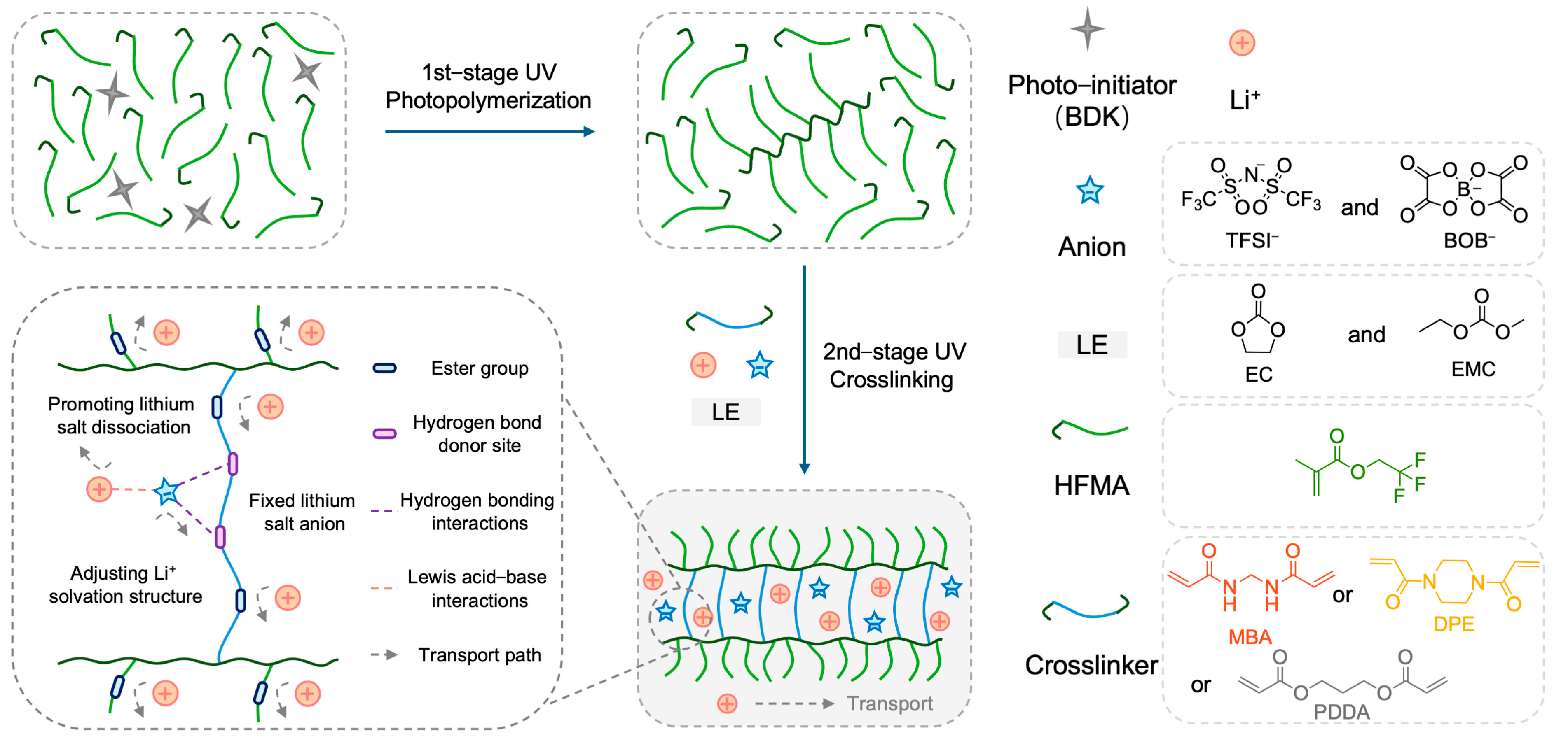
The rational design of the polymer network architecture is paramount for modulating ion transport properties within polymer electrolytes (PEs). This study aimed to enhance Li
+ transport by constructing a crosslinked network incorporating hydrogen–bond–capable amide functionalities, synergistically combined with plasticizers.
Figure 1 illustrates the chemical structures of the key monomers: N,N′–methylenebis(acrylamide) (MBA) as the primary bifunctional crosslinker bearing amide groups, 2,2,2–trifluoroethyl methacrylate (HFMA) as a fluorinated monomer, and comparative crosslinkers 1,4–diacryloylpiperazine (DPE) and propane–1,3–diyl diacrylate (PDDA). Utilizing these components alongside EC/EMC plasticizers and a LiTFSI/LiBOB dual–salt system, three distinct PEs (MFE, DFE, and PFE, corresponding to MBA, DPE, and PDDA crosslinkers, respectively) were synthesized via our previously reported two–stage UV–induced copolymerization strategy [
23,
24]. This strategy is based on the viscosity increase in the partially polymerized HFMA monomer during the first stage of polymerization, as schematically depicted in
Figure 1. The selection of DPE and PDDA, which differ significantly from their corresponding MBA–crosslinked networks in polarity and hydrogen–bonding capability, provides a basis for evaluating the impact of network structure on electrolyte performance.
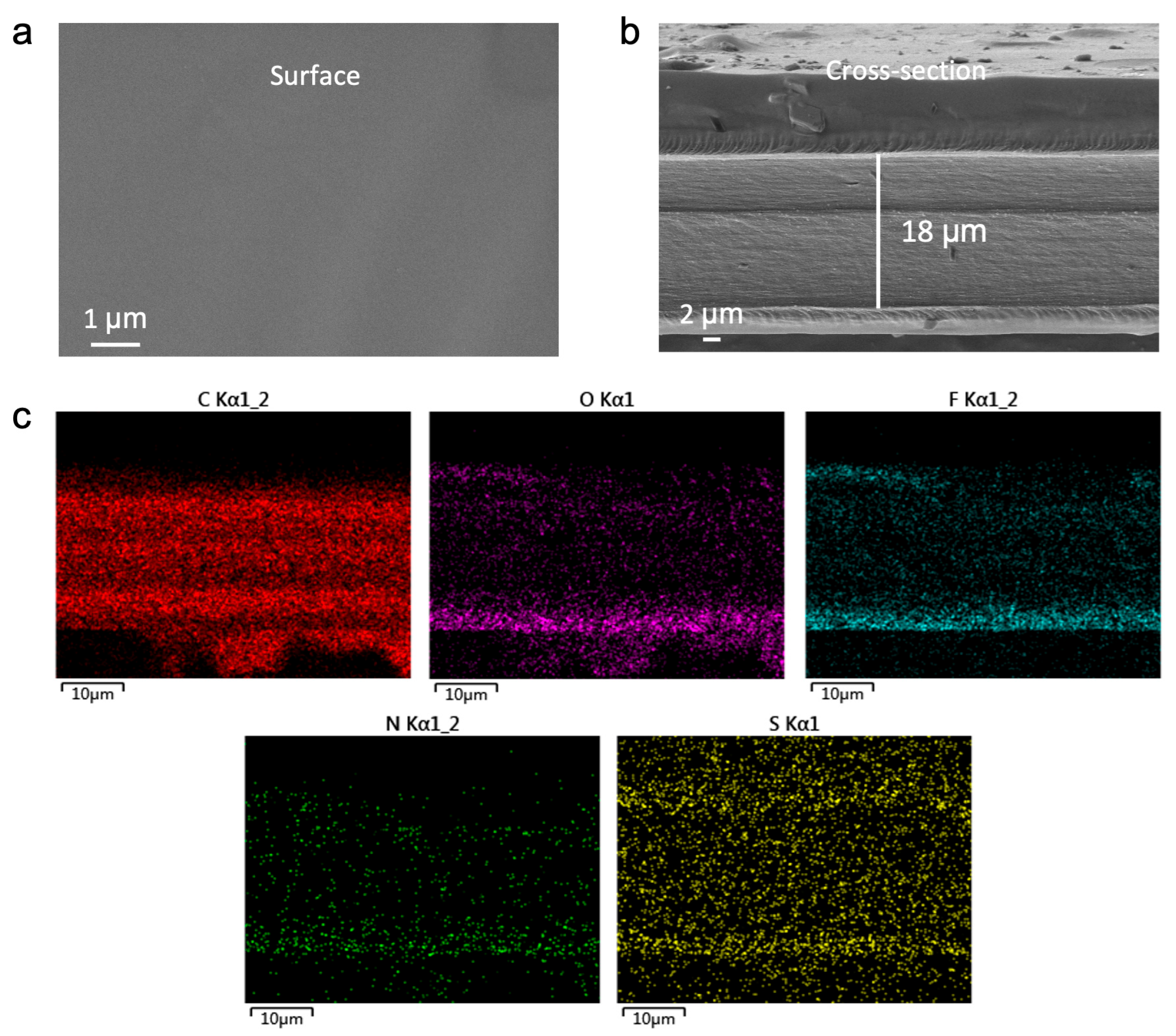
To ascertain the morphological integrity and compositional homogeneity of the fabricated electrolytes, the representative MFE membrane was characterized using scanning electron microscopy (SEM) and energy–dispersive X–ray spectroscopy (EDS). As revealed by the top–view SEM image (
Figure 2a), the MFE membrane exhibits a smooth, dense, and largely defect–free surface, indicative of uniform film formation via the UV polymerization process. Cross–sectional SEM analysis (
Figure 2b) corroborates this uniformity, showing a well–defined polymer layer with a thickness of approximately 18 µm. The compact structure and absence of discernible phase separation between the polymer network and the embedded liquid components attest to successful crosslinking and formulation homogeneity.
EDS elemental mapping (
Figure 2c) provided further insight into the spatial distribution of key constituents within the MFE membrane. The maps demonstrate a homogeneous dispersion of carbon (C), oxygen (O), fluorine (F), nitrogen (N), and sulfur (S) elements throughout the matrix. Particularly noteworthy is the uniform distribution of N (originating from the MBA crosslinker) and F (from the HFMA monomer), confirming their successful and even incorporation into the polymer network. The consistent S signal, primarily attributed to the TFSI
− anions, indicates effective dissolution and dispersion of the lithium salts. Collectively, these SEM and EDS findings validate the excellent structural integrity and compositional uniformity of the MFE electrolyte, establishing critical prerequisites for consistent ion conduction and the formation of continuous ion transport pathways.
2.2. Theoretical Insights: Molecular Interactions, Coordination Environment, and Electronic Structure
To fundamentally elucidate the mechanisms underpinning enhanced ion transport, Density Functional Theory (DFT) calculations and Molecular Dynamics (MD) simulations were performed. These computational approaches provide atomistic– and molecular–level insights into the intricate interplay of intermolecular interactions, electronic structures, and the resultant Li
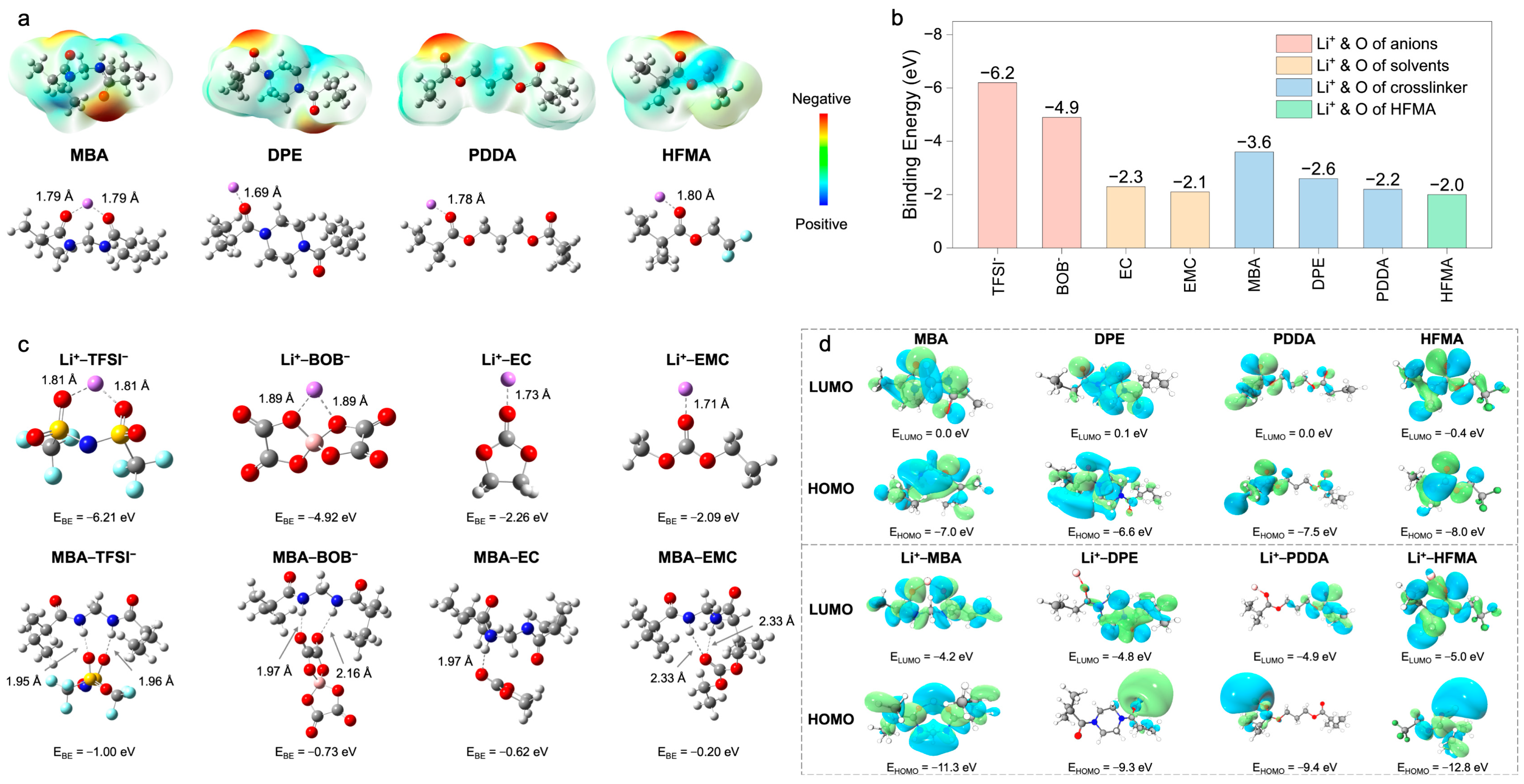
+ coordination environments within the polymer electrolytes (PEs), with a specific focus on delineating the structural influence exerted by different crosslinkers. The initial DFT investigations centered on the electrostatic potential (ESP) distributions of the constituent monomers and their subsequent coordination behavior with Li
+ (
Figure 3a). The ESP map computed for N,N
′–methylenebis(acrylamide) (MBA) prominently features pronounced negative–potential zones localized around the amide carbonyl oxygen atoms. This characteristic signifies a strong electron–donating propensity, thereby facilitating potent, bidentate coordination with Li
+, as evidenced by the calculated short Li–O bond distance of approximately 1.79 Å. In stark contrast, 1,6–diisocyanatohexane–based polyurea (DPE) exhibits a more diffuse ESP landscape, translating into weaker Li
+ coordination (Li–O = 1.69 Å). Poly(ethylene glycol) diacrylate (PDDA) demonstrates intermediate coordination strength (Li–O = 1.78 Å), while hexafluorobutyl methacrylate (HFMA), despite possessing polar ester functionalities, presents a comparatively lower surface electron density and, consequently, a diminished affinity for Li
+ (Li–O = 1.80 Å). This computational evidence collectively suggests that the bifunctional amide groups intrinsic to the MBA structure furnish the most potent and localized coordination sites for Li
+, a feature anticipated to be highly conducive to promoting lithium salt dissociation.
A further quantitative assessment of interaction strengths was performed through binding energy (
) calculations between Li
+ and various electrolyte constituents (
Figure 3b,c). The computations reveal dominant electrostatic attractions governing Li
+–anion interactions (Li
+–TFSI
−: −6.2 eV; Li
+–BOB
−: −4.9 eV), substantially exceeding those observed for Li
+–plasticizer pairings (Li
+–EC: −2.3 eV; Li
+–EMC: −2.1 eV) (
Figure 3b). Although the corresponding short Li–O bond lengths (1.71–1.89 Å,
Figure 3c) corroborate intimate coordination, these potent Li
+–anion associations intrinsically foster the formation of ion aggregates, which detrimentally impede Li
+ mobility. To counteract this unfavorable ion pairing, the MBA crosslinker was strategically incorporated. The DFT calculations confirm that MBA possesses a notably higher preferential binding affinity for Li
+ (−3.6 eV) relative to DPE (−2.6 eV), PDDA (−2.2 eV), and HFMA (−2.0 eV) (
Figure 3b), an advantage primarily attributed to its dual amide configuration. Critically, beyond direct coordination, MBA actively modulates the ionic microenvironment via hydrogen bonding networks (
Figure 3c). It establishes hydrogen bonds with anions (characteristic distances ~1.95–2.16 Å), thereby disrupting direct Li
+–anion coordination shells, and concurrently interacts with solvent molecules (e.g., MBA–EC
: −0.52 eV, distance: ~2.33 Å), influencing the overall Li
+ solvation sheath structure. Consequently, MBA operates synergistically not merely as a passive structural crosslinker but as an active modulator of the Li
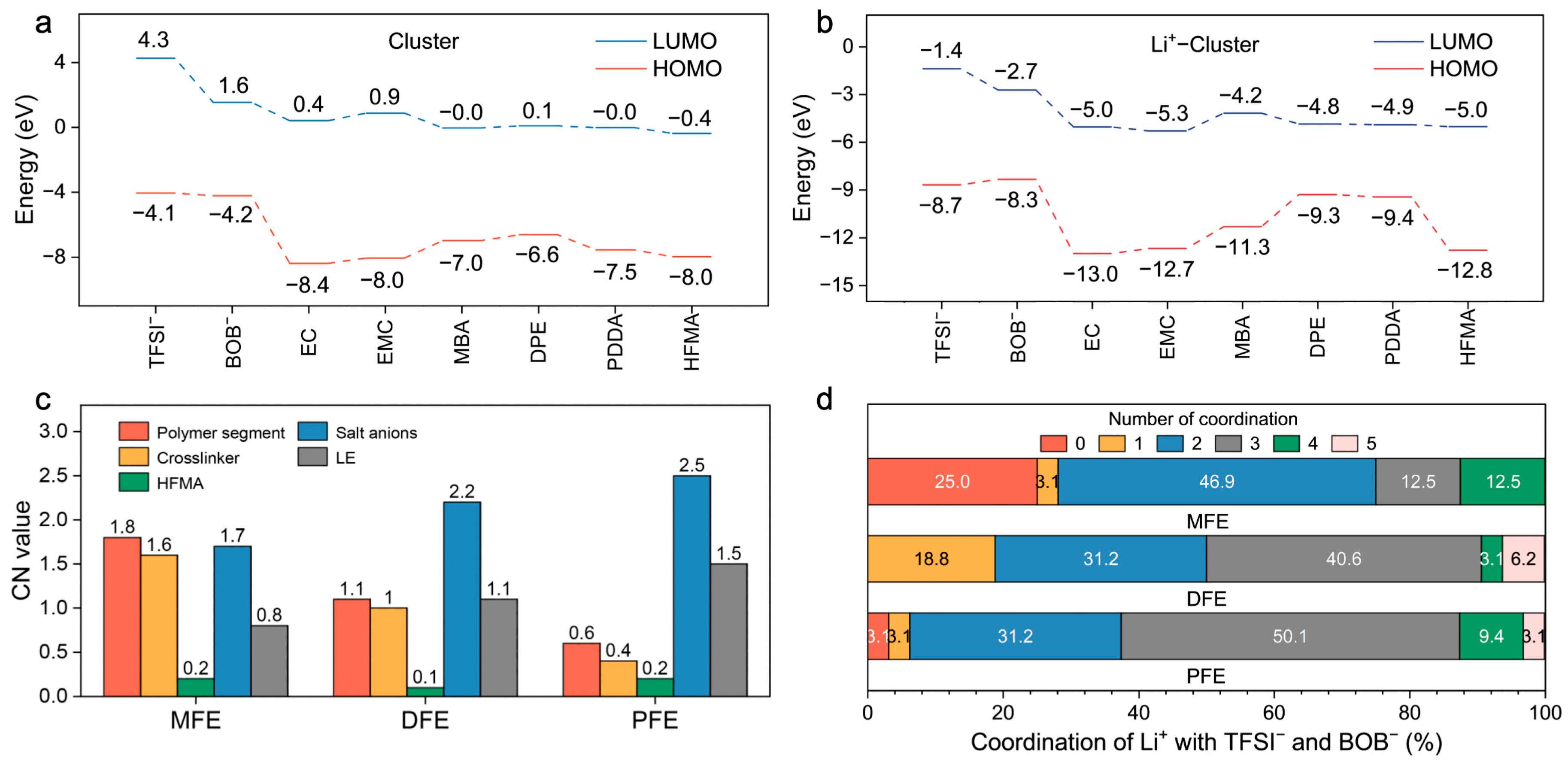
+ coordination sphere, leveraging both direct Lewis acid–base coordination and strategically engineered hydrogen bond interactions to facilitate salt dissociation and restructure the local ionic environment. A complementary analysis of frontier molecular orbitals (HOMO/LUMO) was conducted to evaluate the intrinsic electronic stability (
Figure 3d and
Figure 4a). All monomers exhibit relatively low HOMO energy levels (−6.6 to −8.0 eV), indicative of robust oxidative stability (
Figure 4a). Upon coordination with Li
+, general stabilization (lowering) of all component orbital energy levels is observed, effectively widening the electrochemical stability window of the electrolyte system (
Figure 4b). Notably, the Li
+–MBA complex displays a significantly stabilized HOMO level (−11.3 eV) and the lowest LUMO level (−4.2 eV) among the investigated crosslinker complexes, predicting superior electrochemical resilience against both oxidative and reductive degradation, a finding consistent with its strong Li
+ interaction propensity.
Complementing the static DFT insights, the MD simulations furnished dynamic perspectives on the Li
+ solvation structure, primarily through the analysis of radial distribution functions (RDFs) and coordination numbers (CNs) (
Figure S1a–h and
Figure 4c,d). An examination of the Li
+–polymer RDF profiles (
Figure S1a) reveals the most pronounced peak intensity and, consequently, the highest CN, within the MFE system, with a particular contribution from the MBA units (
Figure S1c). This observation signifies a strong, preferential interaction between Li
+ and the MFE polymer backbone. Conversely, the Li
+–anion RDFs (
Figure S1b,e,f) demonstrate markedly attenuated coordination intensity in the MFE system compared to the DFE and PFE analogs. This finding corroborates the hypothesis that robust Li
+–polymer/solvent interactions, facilitated by the MBA crosslinker in MFE, effectively compete against and diminish direct Li
+–anion pairing. Furthermore, MFE exhibited slightly decreased Li
+–solvent interactions (
Figure S1g) and reduced propensity for Li
+–Li
+ aggregation (
Figure S1h). Quantitative CN analysis (
Figure 4c,d) substantiates these structural observations: Li
+ ions within the MFE network preferentially coordinate with polymer segments (especially MBA moieties), concurrently exhibiting the lowest average CNs with anions and solvent molecules among the systems studied. The distribution of Li
+–anion CNs (
Figure 4d) further underscores this trend; approximately 75% of Li
+ ions in MFE coordinate with two or fewer anions, whereas this percentage markedly decreases in DFE (50.1%) and PFE (37.4%). Collectively, these MD simulation results unequivocally demonstrate that the MBA–based MFE network architecturally fosters a Li
+ solvation environment substantially more conducive to ion transport by promoting Li
+–polymer interactions while simultaneously suppressing deleterious Li
+–anion associations. Studies have demonstrated that the distribution and solvation structure of lithium ions significantly affect ion transport behavior [
25,
26]. Further Mean Squared Displacement (MSD) analysis based on MD simulations (
Figure S2) reveals that the MFE–based polymer electrolyte exhibits a higher Li
+ diffusion coefficient (1.9 × 10
−5 cm
2 s
−1). This value substantially exceeds those calculated for the DFE (1.6 × 10
−5 cm
2 s
−1) and PFE (1.5 × 10
−5 cm
2 s
−1) systems, underscoring the enhanced ion transport dynamics within the MFE matrix. Finally, an analysis of component spatial density profiles derived from the MD simulations was employed to assess the microstructural homogeneity of the systems (
Figure S3a–d). The MFE system displayed conspicuously higher and more uniform density distributions for Li
+ ions (
Figure S3a), polymer ester oxygens (
Figure S3b), and anion–representative atoms (S, B;
Figure S3c–d) throughout the simulation box. In contrast, both DFE and PFE exhibited lower overall densities and more pronounced spatial fluctuations, indicative of less homogeneous microstructures. This comparative analysis strongly suggests that the engineered network incorporating MBA promotes a highly uniform electrochemical environment, likely facilitating the formation of continuous and efficient ion conduction pathways, thereby rationalizing the experimentally observed enhancements in ionic conductivity.
2.3. Electrochemical Performance Evaluation
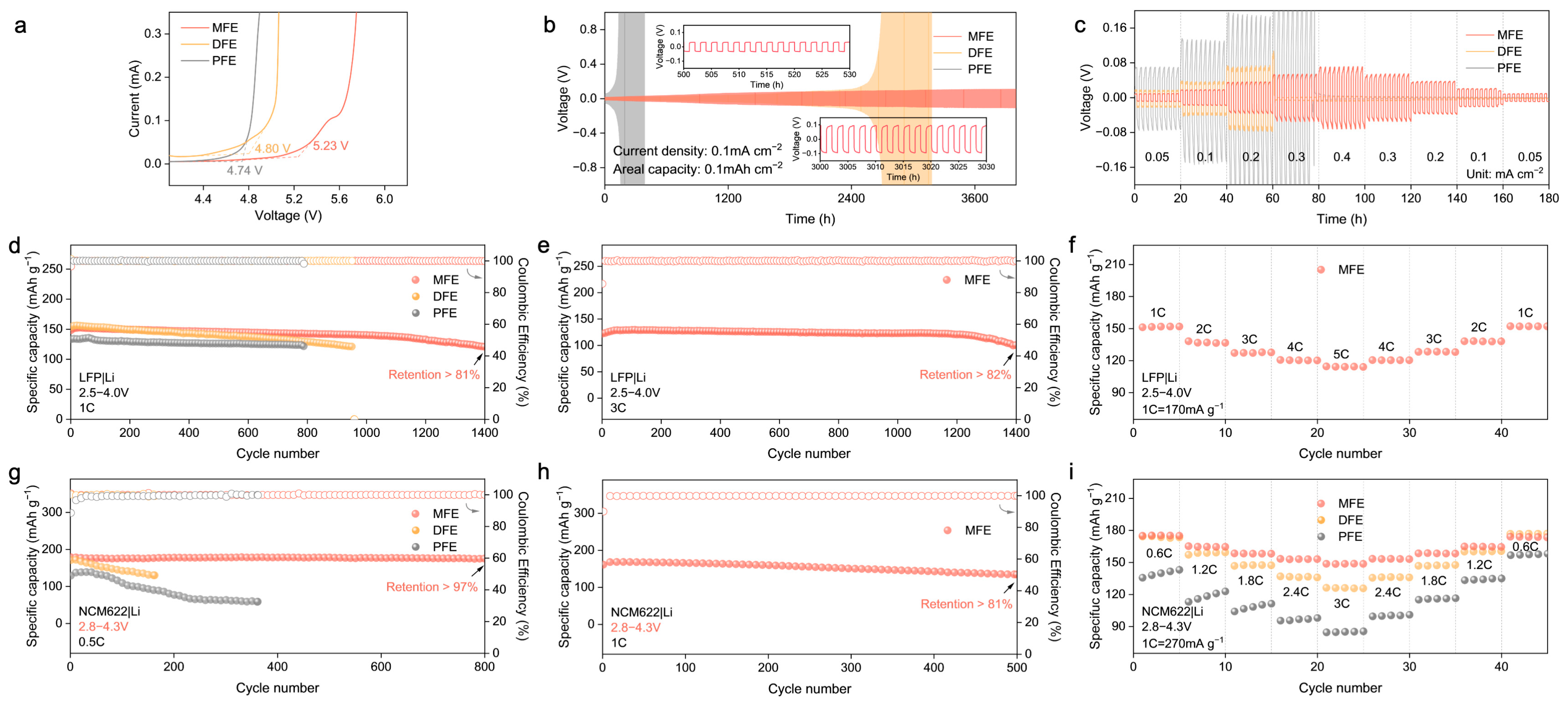
Building upon the structural insights and theoretical predictions highlighting the advantages conferred by the MBA–crosslinked network, the electrochemical performance of the synthesized polymer electrolytes (MFE, DFE, and PFE) was systematically interrogated. Linear sweep voltammetry (LSV) was employed to probe the oxidative stability limits (
Figure 5a and
Figure S4). The MFE electrolyte exhibited markedly enhanced oxidative stability, with electrochemical decomposition commencing at approximately 5.23 V vs. Li/Li
+. This threshold considerably surpasses those observed for DFE (~4.80 V) and PFE (~4.74 V). This expanded electrochemical window, consistent with the DFT–predicted low HOMO energy level and the stabilized Li
+–MBA complex, affirms MFE’s intrinsic compatibility with high–voltage cathode materials. Subsequently, the interfacial stability and compatibility with lithium metal anodes were investigated via galvanostatic cycling of Li|PEs|Li symmetric cells (
Figure 5b,c). The MFE–based cell demonstrated exceptional long–term cycling stability, maintaining operation for over 4000 h at a current density of 0.1 mA cm
−2 with remarkably low and stable voltage polarization (
Figure 5b). This exceptional stability underscores the formation of a highly robust and uniform solid electrolyte interphase (SEI) on the lithium metal anode and testifies to the effective suppression of Li dendrite proliferation facilitated by the MFE structure. In stark contrast, cells utilizing DFE and PFE electrolytes experienced premature failure under identical conditions. The Li|Cu half–cell configuration was used to evaluate the reversibility of lithium plating/stripping in different polymer electrolyte systems via cyclic voltammetry (
Figure S5). Among the three systems, the MFE–based electrolyte exhibited the highest peak current density and most symmetric redox behavior, indicative of highly reversible lithium deposition and stable interfacial kinetics. In contrast, the PFE system showed the lowest current response and pronounced polarization, reflecting poor interfacial compatibility and limited electrochemical reversibility. These results corroborate the superior ion transport and interfacial characteristics of the MFE electrolyte, which can be attributed to its hydrogen–bond–regulated solvation architecture. Furthermore, under incrementally increasing current densities (
Figure 5c), the MFE–based cell consistently sustained the lowest overpotential, underscoring its capacity for stable lithium deposition/stripping processes even at elevated rates.
The practical viability of the MFE electrolyte was further scrutinized in lithium cell configurations employing both LiFePO
4 (LFP) and LiNi
0.6Co
0.2Mn
0.2O
2 (NCM622) cathodes against lithium metal anodes. Within LFP|Li cells (
Figure 5d–f), MFE considerably surpassed the control electrolytes, delivering remarkable long–term cyclability: retaining over 81% of its initial capacity after 1400 cycles at 1C (
Figure 5d). The corresponding evolution of voltage profiles for LFP|Li full cells at the 100th, 200th, and 400th cycles (
Figure S6) further highlighted the minimal capacity decay achieved with the MFE. Impressively, even under a more demanding 3C rate protocol, the MFE–based cell maintained 82% capacity retention after 1400 cycles (
Figure 5e). Moreover, the initial electrochemical impedance spectroscopy (EIS) measurements (
Figure S7) of LFP|Li full cells assembled with the MFE exhibited the lowest interfacial impedance, signifying superior interfacial kinetics and reduced resistance to ion transport. Rate capability assessments (
Figure 5f) further corroborated the superior kinetic performance enabled by MFE, which delivered a substantial capacity of approximately 120 mAh g
−1 at a high rate of 5C, alongside excellent capacity recovery upon returning to lower rates. Transitioning to higher–voltage NCM622|Li cells operating between 2.8 and 4.3 V (
Figure 5g–i), MFE demonstrated similarly superior electrochemical characteristics. At a rate of 0.5C, the MFE cell retained over 97% of its initial discharge capacity after 800 cycles accompanied by near–unity CE, starkly contrasting with the significant capacity decay observed in control cells employing DFE and PFE electrolytes (
Figure 5g and
Figure S8). At an elevated rate of 1C, the MFE cell sustained stable cycling, retaining over 81% capacity after 500 cycles (
Figure 5h). Correspondingly, rate capability evaluations (
Figure 5i) revealed that MFE consistently delivered higher specific capacities across a range of rates from 0.6C to 3C, affirming its capability to facilitate rapid ion transport even under the demanding conditions imposed by the high–voltage cathode. Notably, when benchmarked against previous research on polymer electrolytes (PEs), our MFE system demonstrates superior long–term stability and excellent compatibility with high–voltage cathode materials such as NCM622 (
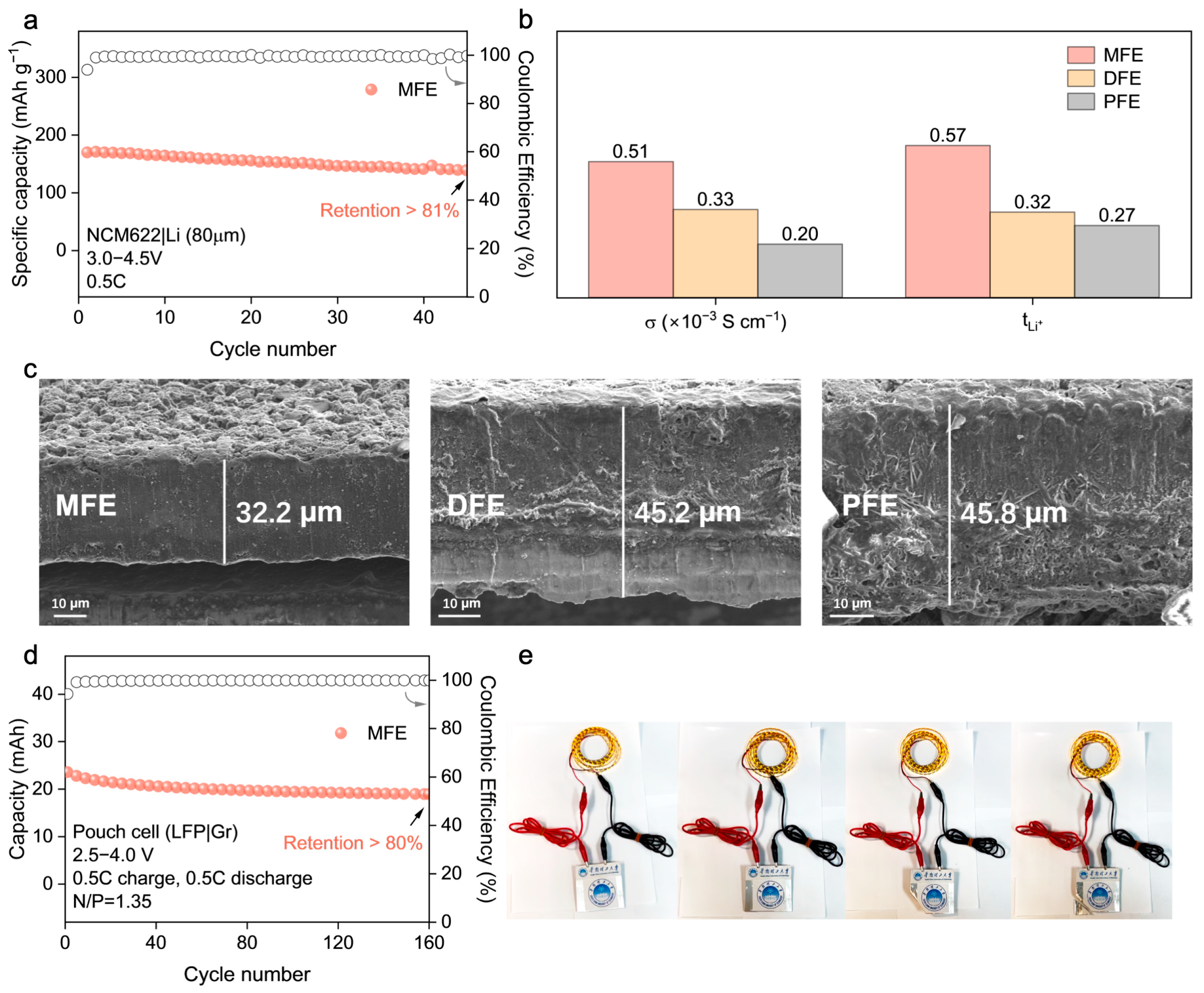
Table S1). Critically, the robustness of the MFE electrolyte was confirmed under more challenging practical conditions, including a high cathode mass loading (~4 mg cm
−2) and an extended voltage window (3.0–4.5 V), where it maintained over 81% capacity retention after 45 cycles at 0.5C (
Figure 6a), highlighting its potential for practical applications.
The origin of MFE’s superior electrochemical performance is elucidated by key ion transport parameters (
Figure 6b,
Figures S9 and S10; Table S2), which provide a clear rationale for its advantageous behavior. MFE distinctly exhibits the highest room–temperature ionic conductivity among the synthesized electrolytes (σ ≈ 5.1 × 10
−4 S cm
−1) alongside a remarkably enhanced Li
+ transference number (
≈ 0.57). These values substantially surpass those measured for DFE (
≈ 0.32) and PFE (
≈ 0.27). This substantially elevated
, corroborated by the computationally predicted reduction in Li
+–anion coordination within the MFE system, confirms that Li
+ migration dominates charge transport. This characteristic is pivotal as it minimizes the formation of concentration polarization gradients during battery operation, thereby contributing significantly to the observed high–rate capability and exceptional cycling stability previously described. Beyond the quantitative transport parameters, the underlying structural origin of the enhanced ion conduction in the MFE system can be further understood by considering the role of hydrogen bonding interactions within the cross–linked polymer network. In particular, both intra–polymer and inter–polymer hydrogen bonds are likely to coexist and synergistically influence ion transport behavior. The bifunctional crosslinker MBA introduces amide groups (–NH–) that serve as hydrogen bond donors. Intra–polymer hydrogen bonds formed within individual chains enhance local rigidity and prevent segmental collapse, preserving favorable polymer chain conformations for Li
+ migration. Meanwhile, inter–polymer hydrogen bonding between adjacent chains contributes to the formation of a dynamic three–dimensional network that promotes both mechanical robustness and ion–conductive continuity. More critically, these hydrogen bonding motifs can selectively interact with the anions of lithium salts, immobilizing them via directional hydrogen bonding and thereby facilitating salt dissociation. This mechanism reduces ion pairing and enhances the effective lithium–ion concentration, which rationalizes the observed improvement in Li
+ transference number and ionic conductivity in the MFE system. Taken together, the dual–mode hydrogen bonding network plays a pivotal role in modulating the solvation environment and constructing efficient ion transport pathways within the polymer matrix.
2.4. Interfacial Stability Analysis and Pouch Cell Validation
Given that the nature of the electrode–electrolyte interphase is a critical determinant of cycling longevity and safety in lithium metal batteries, the morphology of lithium metal anodes retrieved after prolonged cycling (200 cycles in NCM622|PEs|Li cells) was meticulously inspected using Scanning Electron Microscopy (SEM) (
Figure 6c). The anode surface exposed to the MFE electrolyte exhibited a notably smooth and compact deposition morphology, largely devoid of deleterious dendritic protrusions or significant porosity. This favorable morphology strongly indicates the formation of a stable, homogeneous solid electrolyte interphase (SEI) facilitated by the MFE network, which effectively mitigates detrimental localized current fluctuations and regulates uniform lithium deposition/stripping. Conversely, lithium anodes cycled with the DFE and PFE electrolytes displayed pronounced surface roughness characterized by non–uniform deposition patterns and evidence of incipient dendrite formation, observations consistent with, and providing microstructural corroboration for, their previously documented inferior electrochemical cycling stability and higher interfacial impedance.
To further investigate the mechanical properties of the polymer electrolytes (PEs), Atomic Force Microscopy (AFM) was employed, with the results detailed in
Figures S11 and S12. The AFM topography images (
Figure S11) were first analyzed to assess surface roughness. The MFE membrane exhibited the lowest surface roughness (R
q = 16.7 nm, R
a = 13.6 nm), indicative of a dense and uniform polymer network facilitated by MBA–mediated cross–linking and hydrogen bond reinforcement. In contrast, the PFE membrane displayed a significantly rougher surface (R
q = 62.4 nm), suggesting inferior structural uniformity and potentially compromised interfacial compatibility. These observations are consistent with the SEM results presented in
Figure 2. Subsequently, the nanomechanical properties of the polymer electrolyte membranes were evaluated using AFM–based quantitative nanomechanical mapping (QNM), as depicted in
Figure S12. Among the three systems, the MFE membrane demonstrated the highest average Young’s modulus (239 MPa) with a remarkably uniform spatial distribution. This is characteristic of a well–organized and highly crosslinked polymer network, further reinforced by hydrogen bonding. Conversely, the DFE sample showed the lowest modulus (118 MPa) and significant heterogeneity, reflecting a less cohesive structure with potential soft domains. The PFE membrane presented an intermediate Young’s modulus (224 MPa), albeit with greater nanoscale variation, suggesting localized rigidity but reduced overall structural uniformity. These findings underscore the critical role of molecular–level interactions in tailoring the mechanical robustness of PEs. Such robustness is essential for ensuring stable interfacial contact and effectively suppressing dendrite growth in LIBs.
To evaluate the practical applicability and potential for scalability of the optimized MFE system, prototype LFP|graphite (Gr) pouch cells were constructed and subjected to rigorous electrochemical testing (
Figure 6d and
Figure S14). These pouch cells demonstrated robust and stable cycling performance, retaining over 80% of their initial discharge capacity after 160 cycles under a 0.5C rate. This successful validation in a relevant device format not only confirms MFE’s electrochemical efficacy but also attests to its compatibility with commercially prevalent electrode materials (LFP, graphite) sufficient for practical cell assembly. The functional viability was further underscored by the demonstration of a fabricated pouch cell powering an array of light–emitting diodes (LEDs) (
Figure 6e), visually confirming its potential for tangible energy storage applications.


