

A Comparison between Triphenylmethyl and Triphenylsilyl Spirobifluorenyl Hosts: Synthesis, Photophysics and Performance in Phosphorescent Organic Light-Emitting Diodes

 , , , and
Abstract
1. Introduction
2. Results
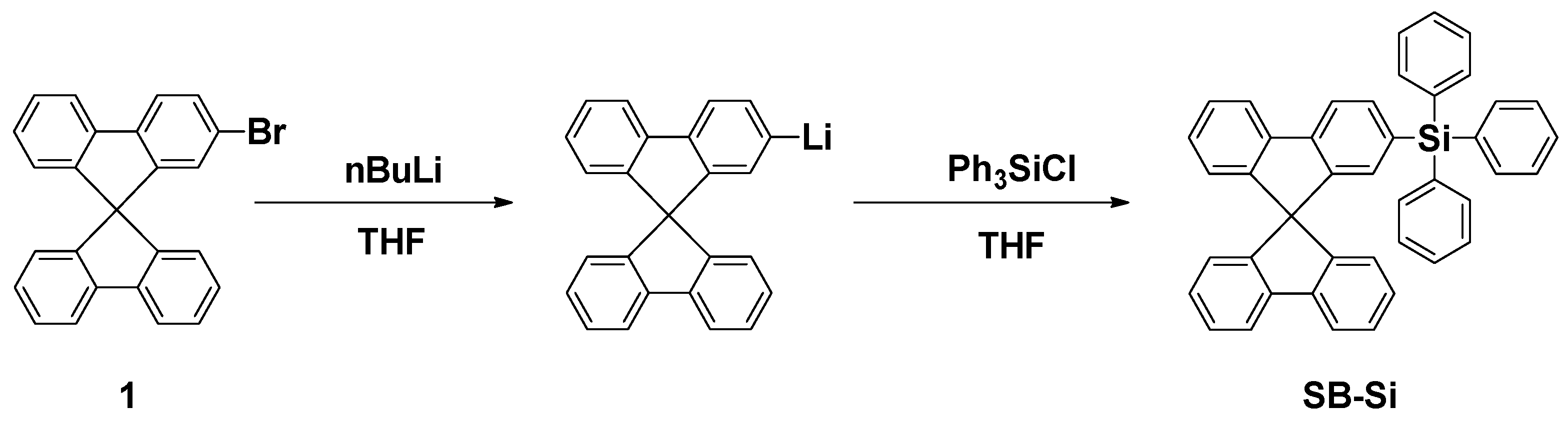
2.1. Synthesis
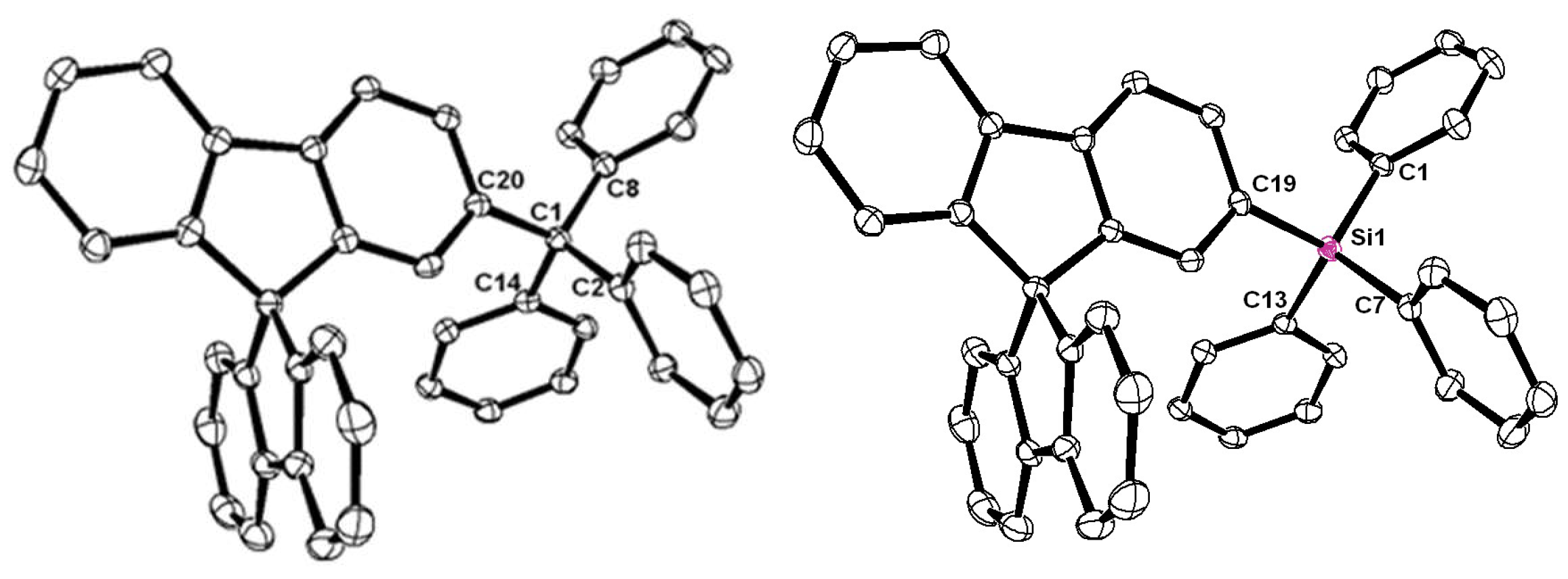
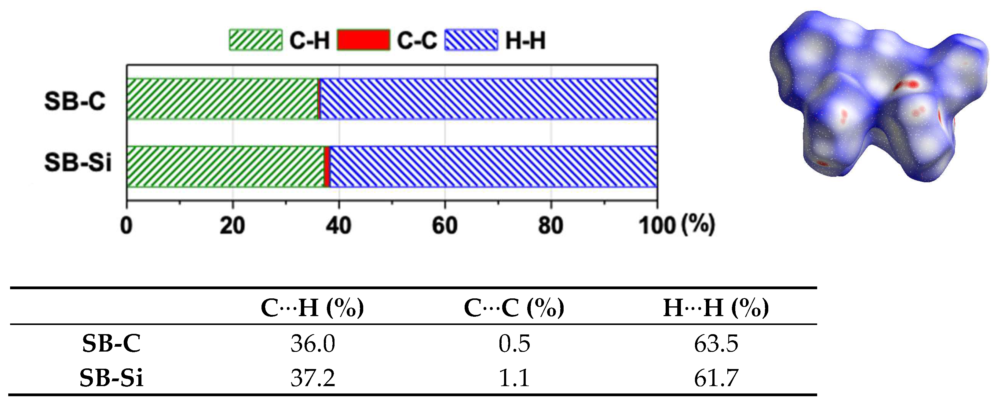
2.2. X-ray Structures
2.3. Theoretical Calculations
2.4. Electrochemistry
2.5. Thermal Properties
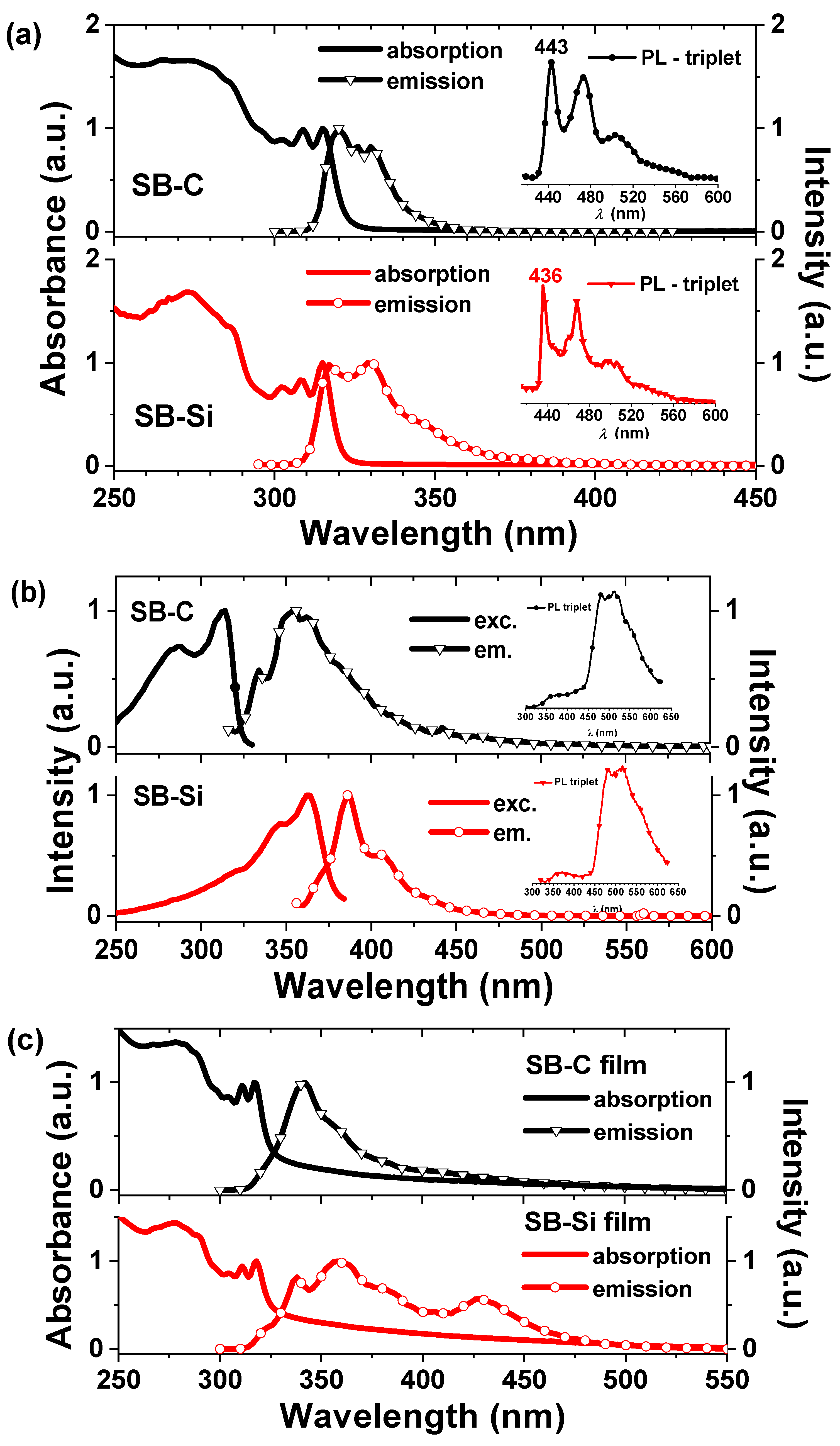
2.6. Photophysics
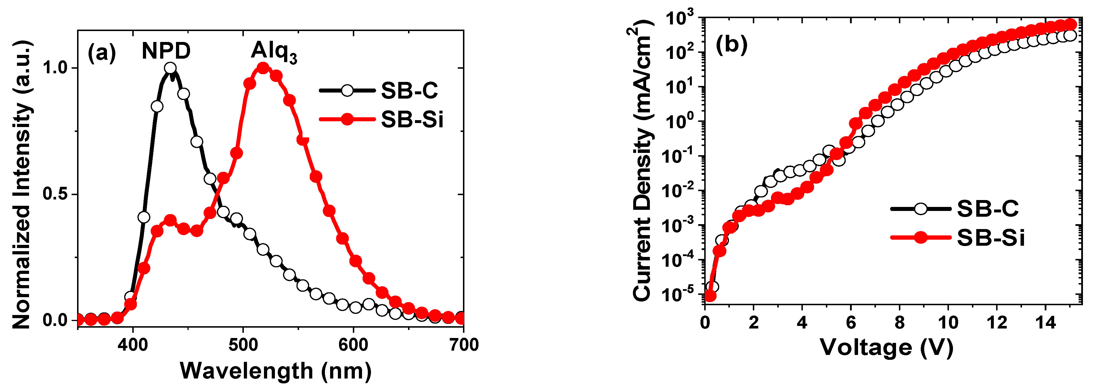
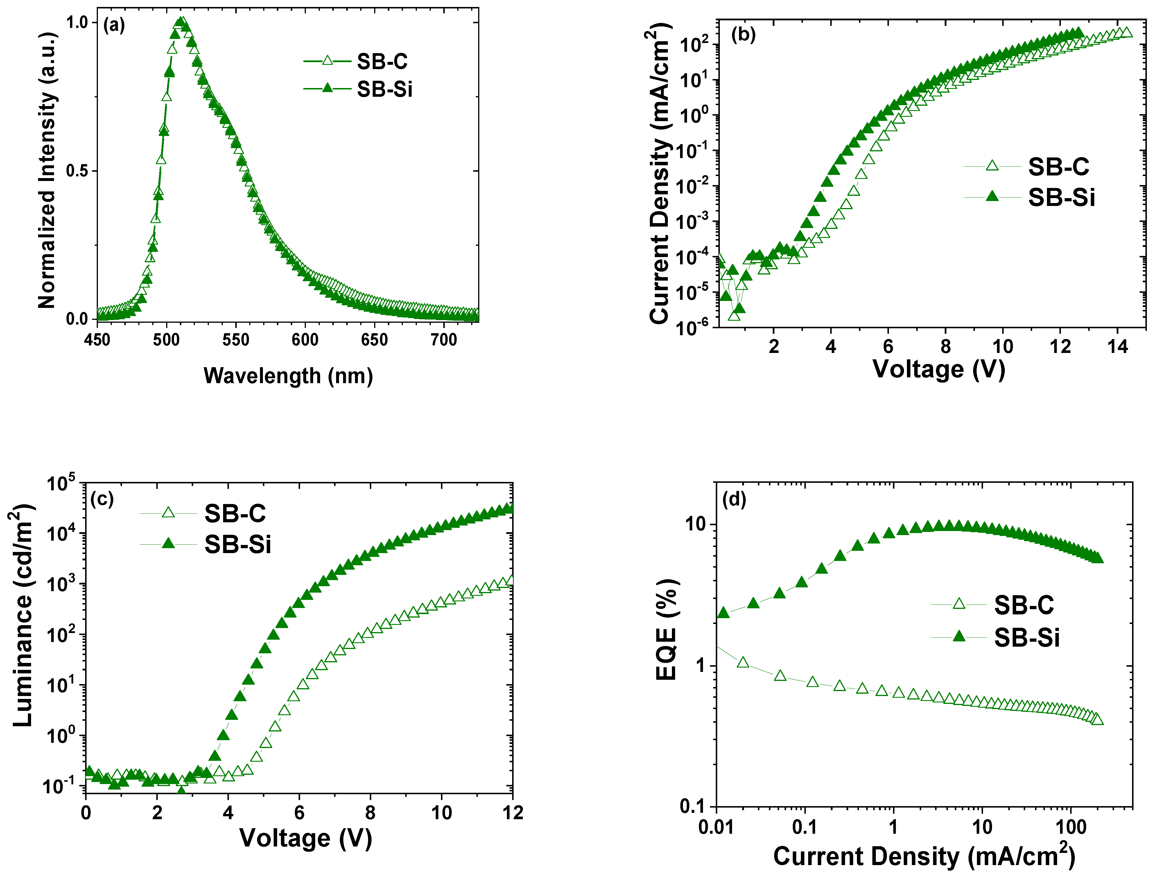
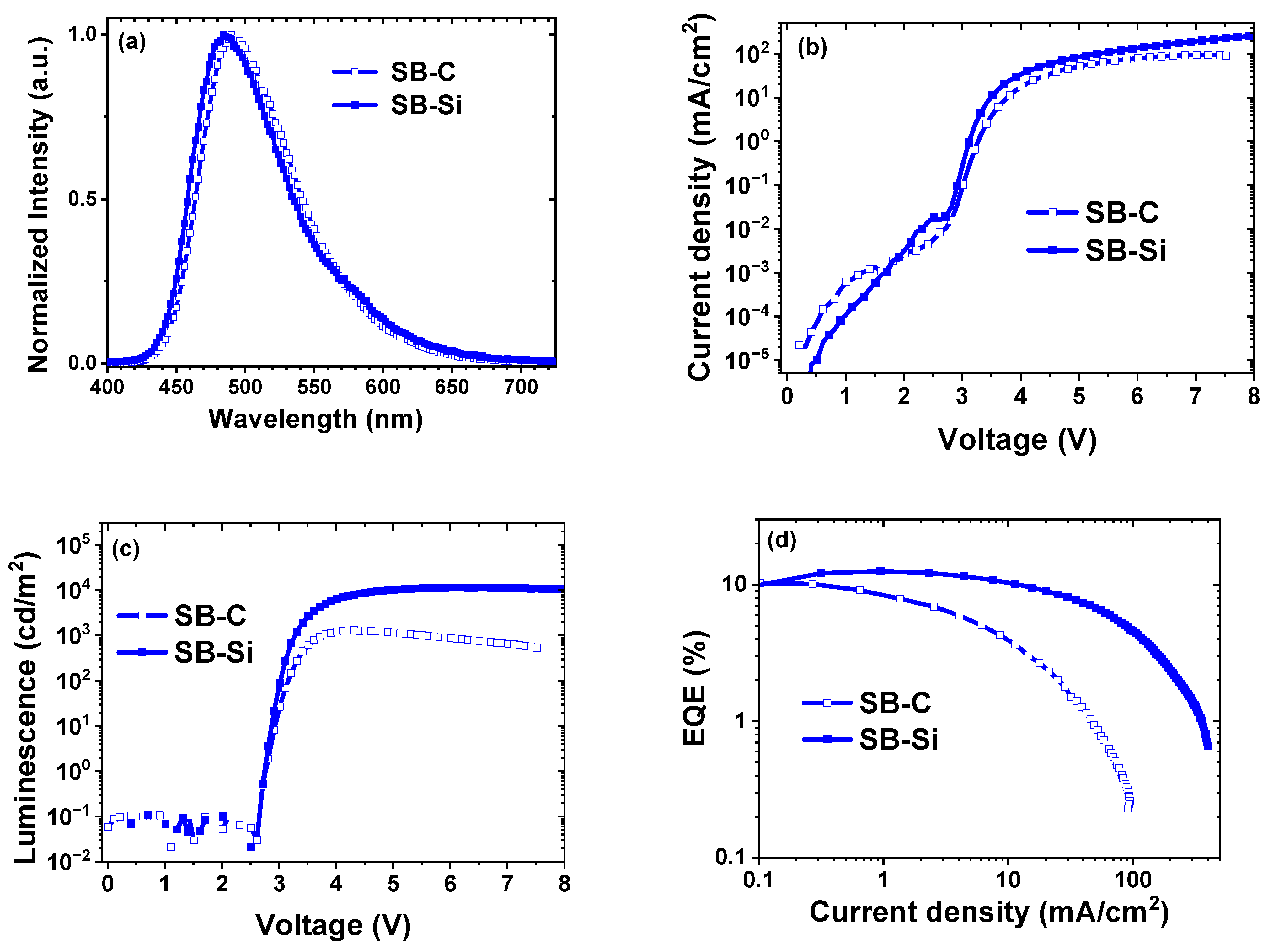
2.7. OLED Studies
3. Materials and Methods
3.1. Synthesis
- Triphenyl-9,9-spirobifluoren-2-yl silane (SB-Si) [24,25]. To a solution of 0.78 g (2 mmol) 2-bromo-9,9-spirobifluorene (1) in dry THF was added 1.38 mL (2.2 mmol) of n-BuLi (1.6 M in hexanes) under an N2 atmosphere to obtain an orange solution. Triphenylchlorosilane (0.56 g, 1.9 mmol) was initially weighed and dissolved in THF under an N2 atmosphere and was added using a syringe into the solution after 1 h. The solution was stirred overnight. Ethyl acetate and water were used to extract the organic layer, which was later dried over brine and magnesium sulfate. Organic solvents were reduced by rotary evaporation to obtain an orange-colored solid that was recrystallized in CH2Cl2 to obtain 0.89 g of a white solid product.
- Triphenyl-9,9-spirobifluoren-2-yl methane (SB-C). A solution of 1.74 g 1 was added dropwise to Mg in 8 mL of THF. A solution of benzylphenone in 4 mL of THF was slowly added into the prepared Grignard reagent at room temperature, and the mixture was refluxed for three hours. After being cooled down to room temperature, ammonium chloride was used to quench the reaction. The organic layer was extracted by CH2Cl2 and dried over MgSO4. After the solvent was removed using rotary evaporation, a silica gel column with CH2Cl2/hexanes (1:3) was performed to yield 1.63 g of diphenyl-spirobifluorenyl methanol (2) as a white solid a yield of 81%. Compound 2 (3.17 mmol, 1.58 g) was refluxed with aniline (4.8 mmol, 0.44 mL), HCl (0.5 mL) and acetic acid (10 mL) at 140 °C for 3 days. The reaction mixture was allowed to cool down to room temperature, and 100 mL of water was added. NaOH solid was added until the solution became neutral. The product was filtered out as 1.65 g of a white solid of diphenylspirobifluorenylaniline methane (3). To a solution of 0.57 g of 3 in 30 mL of THF, a solution of 6 mmol of H3PO2 in H2O (0.5 mL) was added. After stirring for 10 min, a solution of tBuONO in 5 mL of THF was added, and the mixture was stirred for 16 h at 40 °C. After the THF was removed, the reaction mixture was extracted with CH2Cl2 and water. The organic layer was washed with brine and dried over MgSO4. After the solvent was removed with reduced pressure, recrystallization was performed to yield 2.51 g of a white solid as the product.
- Triphenyl-9,9-spirobifluoren-2-yl silane (SB-Si), yield 78%. 1H NMR (CDCl3, 250 Hz): δ 7.80–7.87 (2H, dd, Ar-H), 7.74–7.78 (2H, d, Ar-H), 7.45–7.49 (1H, d, Ar-H), 7.29–7.41 (12H, m, Ar-H), 7.20–7.27 (5H, m, Ar-H), 7.08–7.15 (4H, dd, Ar-H), 7.05 (1H, s, Ar-H), 6.75–6.79 (2H, d, Ar-H), 6.71–6.75 (1H, d, Ar-H). MS (m/z): 574, 497, 316, 259. Ana. Calcd. for C43H30Si: C 89.85 H 5.26; found: C 90.07 H 5.12.
- Diphenyl-9,9-spirobifluoren-2-yl methanol (2), yield 81%. 1H NMR (CDCl3, 400 Hz) δ: 7.79–7.81 (1H, d, Ar-H), 7.77–7.79 (2H, d, Ar-H), 7.69–7.71 (1H, d, Ar-H), 7.33–7.38 (1H, d, Ar-H), 7.31–7.36 (2H, dd, Ar-H), 7.18–7.22 (4H, d, Ar-H), 7.18–7.21 (2H, dd, Ar-H), 7.12–7.17 (4H, dd, Ar-H), 7.04–7.10 (1H, dd, Ar-H), 6.92 (1H, s, Ar-H), 6.72–6.75 (2H, d, Ar-H), 6.67–6.70 (1H, d, Ar-H). MS (m/z): 498, 482, 421, 315.
- p-(Diphenyl-9,9-spirobifluoren-2-yl)methyl aniline (3), yield 91%. 1H NMR (CDCl3, 250 Hz): δ 7.75–7.79 (1H, d, Ar-H) 7.69–7.73 (2H, d, Ar-H), 7.25–7.32 (3H, m, Ar-H), 7.21–7.24 (1H, d, Ar-H), 7.01–7.10 (11H, m, Ar-H), 6.80–6.83 (2H, d, Ar-H), 6.68–6.71 (2H, d, Ar-H), 6.65–6.68 (1H, d, Ar-H), 6.56–6.58 (1H, s, Ar-H), 6.40–6.43 (2H, d, Ar-H). MS (m/z): 572, 481, 258.
- Triphenyl-9,9-spirobifluoren-2-yl methane (SB-C), yield 45%. 1H NMR (CDCl3, 400 Hz) δ: 7.76–7.79 (1H, d, Ar-H), 7.71–7.73 (2H, dd, Ar-H), 7.68–7.70 (1H, d, Ar-H), 7.30–7.34 (1H, dd, Ar-H), 7.27–7.31 (2H, dd, Ar-H), 7.23–7.26 (1H, d, Ar-H), 7.03–7.12 (18H, m, Ar-H), 6.68–6.70 (2H, d, Ar-H), 6.62–6.68 (1H, d, Ar-H), 6.55 (1H, s, Ar-H). MS (m/z): 558, 481, 403, 316. Ana. Calcd. for C44H30: C 94.59 H 5.41; found: C 94.45; H 5.31.
3.2. X-ray Crystallography
3.3. Thermal Analysis
3.4. Electrochemistry and Photochemistry
3.5. Device Fabrication
4. Summary
Supplementary Materials
Author Contributions
Funding
Data Availability Statement
Acknowledgments
Conflicts of Interest
Sample Availability
References
- Adachi, C.; Baldo, M.A.; Thompson, M.E.; Forrest, S.R. Nearly 100% internal phosphorescence efficiency in an organic light emitting device. J. Appl. Phys. 2001, 90, 5048–5051. [Google Scholar] [CrossRef]
- Kawamura, Y.; Goushi, K.; Brooks, J.; Brown, J.J.; Sasabe, H.; Adachi, C. 100% phosphorescence quantum efficiency of Ir(III) complexes in organic semiconductor films. Appl. Phys. Lett. 2005, 86, 071104. [Google Scholar] [CrossRef]
- Baldo, M.A.; O’Brien, D.F.; Thompson, M.E.; Forrest, S.R. Excitonic singlet-triplet ratio in a semiconducting organic thin film. Phys. Rev. B 1999, 60, 14422. [Google Scholar] [CrossRef]
- Scholz, S.; Corten, C.; Walzer, K.; Kuckling, D.; Leo, K. Photochemical reactions in organic semiconductor thin films. Org. Electron. 2007, 8, 709–717. [Google Scholar] [CrossRef]
- Scholz, S.; Walzer, K.; Leo, K. Analysis of complete organic semicondnctor devices by laser desorption/ionization time-of-flight mass spectrometry. Adv. Funct. Mater. 2008, 18, 2541–2547. [Google Scholar] [CrossRef]
- Kondakov, D.Y.; Lenhart, W.C.; Nichols, W.F. Operational degradation of organic light-emitting diodes: Mechanism and identification of chemical products. J. Appl. Phys. 2007, 101, 024512. [Google Scholar] [CrossRef]
- Lin, W.C.; Wang, W.B.; Lin, Y.C.; Yu, B.Y.; Chen, Y.Y.; Hsu, M.F.; Jou, J.H.; Shyue, J.J. Migration of small molecules during the degradation of organic light-emitting diodes. Org. Electron. 2009, 10, 581–586. [Google Scholar] [CrossRef]
- Sivasubramaniam, V.; Brodkorb, F.; Hanning, S.; Loebl, H.P.; van Elsbergen, V.; Boerner, H.; Scherf, U.; Kreyenschmidt, M. Fluorine cleavage of the light blue heteroleptic triplet emitter FIrpic. J. Fluor. Chem. 2009, 130, 640–649. [Google Scholar] [CrossRef]
- Holmes, R.J.; Forrest, S.R.; Tung, Y.J.; Kwong, R.C.; Brown, J.J.; Garon, S.; Thompson, M.E. Blue organic electrophosphorescence using exothermic host-guest energy transfer. Appl. Phys. Lett. 2003, 82, 2422–2424. [Google Scholar] [CrossRef]
- D’Andrade, B.W.; Forrest, S.R. Effects of exciton and charge confinement on the performance of white organic p-i-n electrophosphorescent emissive excimer devices. J. Appl. Phys. 2003, 94, 3101–3109. [Google Scholar] [CrossRef]
- O’Brien, D.F.; Baldo, M.A.; Thompson, M.E.; Forrest, S.R. Improved energy transfer in electrophosphorescent devices. Appl. Phys. Lett. 1999, 74, 442–444. [Google Scholar] [CrossRef]
- Baldo, M.A.; Lamansky, S.; Burrows, P.E.; Thompson, M.E.; Forrest, S.R. Very high-efficiency green organic light-emitting devices based on electrophosphorescence. Appl. Phys. Lett. 1999, 75, 4–6. [Google Scholar] [CrossRef]
- Ren, X.F.; Li, J.; Holmes, R.J.; Djurovich, P.I.; Forrest, S.R.; Thompson, M.E. Ultrahigh energy gap hosts in deep blue organic electrophosphorescent devices. Chem. Mater. 2004, 16, 4743–4747. [Google Scholar] [CrossRef]
- Holmes, R.J.; D’Andrade, B.W.; Forrest, S.R.; Ren, X.; Li, J.; Thompson, M.E. Efficient, deep-blue organic electrophosphorescence by guest charge trapping. Appl. Phys. Lett. 2003, 83, 3818–3820. [Google Scholar] [CrossRef]
- Shih, P.I.; Chien, C.H.; Chuang, C.Y.; Shu, C.F.; Yang, C.H.; Chen, J.H.; Chi, Y. Novel host material for highly efficient blue phosphorescent OLEDs. J. Mater. Chem. 2007, 17, 1692–1698. [Google Scholar] [CrossRef]
- Wei, W.; Djurovich, P.I.; Thompson, M.E. Properties of Fluorenyl Silanes in Organic Light Emitting Diodes. Chem. Mater. 2010, 22, 1724–1731. [Google Scholar] [CrossRef]
- Wong, K.-T.; Liao, Y.-L.; Lin, Y.-T.; Su, H.-C.; Wu, C.-c. Spiro-Configured Bifluorenes: Highly Efficient Emitter for UV Organic Light-Emitting Device and Host Material for Red Electrophosphorescence. Org. Lett. 2005, 7, 5131–5134. [Google Scholar] [CrossRef]
- Wu, C.-c.; Liu, T.-L.; Hung, W.-Y.; Lin, Y.-T.; Wong, K.-T.; Chen, R.-T.; Chen, Y.-M.; Chien, Y.-Y. Unusual Nondispersive Ambipolar Carrier Transport and High Electron Mobility in Amorphous Ter(9,9-diarylfluorene)s. J. Am. Chem. Soc. 2003, 125, 3710–3711. [Google Scholar] [CrossRef]
- Thiery, S.; Tondelier, D.; Declairieux, C.; Seo, G.; Geffroy, B.; Jeannin, O.; Rault-Berthelot, J.; Métivier, R.; Poriel, C. 9,9′-Spirobifluorene and 4-phenyl-9,9′-spirobifluorene: Pure hydrocarbon small molecules as hosts for efficient green and blue PhOLEDs. J. Mater. Chem. C 2014, 2, 4156–4166. [Google Scholar] [CrossRef]
- Tian, G.; Jiang, Y.; Wu, P.; Huang, J.; Zou, Q.; Wang, Q.; Mu, H.; Su, J. Pure hydrocarbon host materials based on spirofluorene with excellent performances for green phosphorescent light-emitting devices. New J. Chem. 2016, 40, 9500–9506. [Google Scholar] [CrossRef]
- Jiang, Z.; Yao, H.; Zhang, Z.; Yang, C.; Liu, Z.; Tao, Y.; Qin, J.; Ma, D. Novel Oligo-9,9′-spirobifluorenes through ortho-Linkage as Full Hydrocarbon Host for Highly Efficient Phosphorescent OLEDs. Org. Lett. 2009, 11, 2607–2610. [Google Scholar] [CrossRef] [PubMed]
- Fan, C.; Chen, Y.; Gan, P.; Yang, C.; Zhong, C.; Qin, J.; Ma, D. Tri-, Tetra- and Pentamers of 9,9′-Spirobifluorenes through Full ortho-Linkage: High Triplet-Energy Pure Hydrocarbon Host for Blue Phosphorescent Emitter. Org. Lett. 2010, 12, 5648–5651. [Google Scholar] [CrossRef] [PubMed]
- Sicard, L.J.; Li, H.-C.; Wang, Q.; Liu, X.-Y.; Jeannin, O.; Rault-Berthelot, J.; Liao, L.-S.; Jiang, Z.-Q.; Poriel, C. C1-Linked Spirobifluorene Dimers: Pure Hydrocarbon Hosts for High-Performance Blue Phosphorescent OLEDs. Angew. Chem. Int. Ed. 2019, 58, 3848–3853. [Google Scholar] [CrossRef]
- Jeong, S.; Cho, S.; Lee, H.W.; Kim, Y.K.; Yoon, S.S. Triphenylsilane-Fluorene Hybrids as Host Materials for Green and Blue Phosphorescent Organic Light Emitting Diodes. J. Nanosci. Nanotechnol. 2017, 17, 5550–5555. [Google Scholar] [CrossRef]
- Kim, H.M.; Seo, J.H.; Lee, K.H.; Kang, H.J.; Yoon, S.S.; Kim, Y.K. Highly Efficient Phosphorescent Green Organic Light-Emitting Diodes with High Energy Gap Host Materials. Mol. Cryst. Liq. Cryst. 2010, 530, 83–239. [Google Scholar] [CrossRef]
- Wei, W. High Energy Hosts and Blue Emitters for Phosphorescent Organic Light Emitting Diodes. Ph.D. Thesis, University of Southern California, Los Angeles, CA, USA, 2010. (Publication No. 3434530) ProQuest Dissertations and Theses Global. [Google Scholar]
- Spackman, M.A.; Jayatilaka, D. Hirshfeld surface analysis. Crystengcomm 2009, 11, 19–32. [Google Scholar] [CrossRef]
- Rault-Berthelot, J.; Granger, M.M.; Mattiello, L. Anodic oxidation of 9,9’-spirobifluorene in CH2Cl2 + 0.2 M Bu4NBF4. Electrochemical behaviour of the derived oxidation product. Synth. Met. 1998, 97, 211–215. [Google Scholar] [CrossRef]
- Ye, S.H.; Liu, Y.Q.; Di, C.A.; Xi, H.X.; Wu, W.P.; Wen, Y.G.; Lu, K.; Du, C.Y.; Liu, Y.; Yu, G. Wide-Energy-Gap Host Materials for Blue Phosphorescent Organic Light-Emitting Diodes. Chem. Mater. 2009, 21, 1333–1342. [Google Scholar] [CrossRef]
- Sworakowski, J.; Lipiński, J.; Janus, K. On the reliability of determination of energies of HOMO and LUMO levels in organic semiconductors from electrochemical measurements. A simple picture based on the electrostatic model. Org. Electron. 2016, 33, 300–310. [Google Scholar] [CrossRef]
- O’Brien, D.F.; Burrows, P.E.; Forrest, S.R.; Koene, B.E.; Loy, D.E.; Thompson, M.E. Hole transporting materials with high glass transition temperatures for use in organic light-emitting devices. Adv. Mater. 1998, 10, 1108. [Google Scholar] [CrossRef]
- Koene, B.E.; Loy, D.E.; Thompson, M.E. Asymmetric triaryldiamines as thermally stable hole transporting layers for organic light-emitting devices. Chem. Mater. 1998, 10, 2235–2250. [Google Scholar] [CrossRef]
- Shirota, Y. Organic materials for electronic and optoelectronic devices. J. Mater. Chem. 2000, 10, 1–25. [Google Scholar] [CrossRef]
- Shirota, Y. Photo- and electroactive amorphous molecular materials—molecular design, syntheses, reactions, properties, and applications. J. Mater. Chem. 2005, 15, 75–93. [Google Scholar] [CrossRef]
- Poriel, C.; Liang, J.-J.; Rault-Berthelot, J.; Barrière, F.; Cocherel, N.; Slawin, A.M.Z.; Horhant, D.; Virboul, M.; Alcaraz, G.; Audebrand, N.; et al. Dispirofluorene–Indenofluorene Derivatives as New Building Blocks for Blue Organic Electroluminescent Devices and Electroactive Polymers. Chem.-A Eur. J. 2007, 13, 10055–10069. [Google Scholar] [CrossRef] [PubMed]
- Weisburger, J.H.; Weisburger, E.K.; Ray, F.E. Some derivatives of 9,9’-spirobifluorene. J. Am. Chem. Soc. 1950, 72, 4253–4255. [Google Scholar] [CrossRef]
- Idris, M.; Kapper, S.C.; Tadle, A.C.; Batagoda, T.; Muthiah Ravinson, D.S.; Abimbola, O.; Djurovich, P.I.; Kim, J.; Coburn, C.; Forrest, S.R.; et al. Blue Emissive fac/mer-Iridium (III) NHC Carbene Complexes and their Application in OLEDs. Adv. Opt. Mater. 2021, 9, 2001994. [Google Scholar] [CrossRef]


| Eox a (V) | Ered b (V) | HOMO c (eV) | LUMO c (eV) | |
|---|---|---|---|---|
| SB-C | 1.25 | −3.00 | −6.2 | −1.3 |
| SB-Si | 1.34 | −2.82 | −6.3 | −1.5 |
| Tm (°C) | Tg (°C) | Tsub (°C) | |
|---|---|---|---|
| SB-C | 284 | - | 245 |
| SB-Si | 253 | 87 | 245 |
| λAbs a (nm) | λPL a (nm) | λPL,77K a (nm) | λExc, crystal b (nm) | λPL, crystal b (nm) | λPL, 77K crystal b (nm) | λAbs, film c (nm) | λPL, film c (nm) | |
|---|---|---|---|---|---|---|---|---|
| SB-C | 315 | 320 | 443 | 314 | 356 | 480 | 317 | 342 |
| SB-Si | 315 | 318 | 436 | 362 | 386 | 480 | 318 | 360, 430 |
| EML | Vturn-on a (V) | EQEmax (%) | @ 1000 cd m−2 | λmax (nm), CIE | |
|---|---|---|---|---|---|
| EQE (%) | J (mA/cm2) | ||||
| 9 wt% Ir(ppy)3 | |||||
| SB-C | 5.2 | 1.2 | 0.6 | 61.9 | 511, (0.28, 0.61) |
| SB-Si | 3.9 | 9.6 | 9.6 | 3.2 | 512, (0.28, 0.63) |
| 20 wt% Ir(tpz)3 | |||||
| SB-C | 2.8 | 10.2 | 3.6 | 11.4 | 488, (0.26, 0.54) |
| SB-Si | 2.8 | 12.6 | 11.7 | 4.4 | 483, (0.20, 0.43) |
Disclaimer/Publisher’s Note: The statements, opinions and data contained in all publications are solely those of the individual author(s) and contributor(s) and not of MDPI and/or the editor(s). MDPI and/or the editor(s) disclaim responsibility for any injury to people or property resulting from any ideas, methods, instructions or products referred to in the content. |
© 2023 by the authors. Licensee MDPI, Basel, Switzerland. This article is an open access article distributed under the terms and conditions of the Creative Commons Attribution (CC BY) license (https://creativecommons.org/licenses/by/4.0/).
Share and Cite
Wei, W.; Ma, J.; Schaab, J.; Brooks, J.; Kang, S.; Whited, M.T.; Djurovich, P.I.; Thompson, M.E. A Comparison between Triphenylmethyl and Triphenylsilyl Spirobifluorenyl Hosts: Synthesis, Photophysics and Performance in Phosphorescent Organic Light-Emitting Diodes. Molecules 2023, 28, 5241. https://doi.org/10.3390/molecules28135241
Wei W, Ma J, Schaab J, Brooks J, Kang S, Whited MT, Djurovich PI, Thompson ME. A Comparison between Triphenylmethyl and Triphenylsilyl Spirobifluorenyl Hosts: Synthesis, Photophysics and Performance in Phosphorescent Organic Light-Emitting Diodes. Molecules. 2023; 28(13):5241. https://doi.org/10.3390/molecules28135241
Chicago/Turabian StyleWei, Wei, Jie Ma, Jonas Schaab, Jason Brooks, Seogshin Kang, Matthew T. Whited, Peter I. Djurovich, and Mark E. Thompson. 2023. "A Comparison between Triphenylmethyl and Triphenylsilyl Spirobifluorenyl Hosts: Synthesis, Photophysics and Performance in Phosphorescent Organic Light-Emitting Diodes" Molecules 28, no. 13: 5241. https://doi.org/10.3390/molecules28135241
APA StyleWei, W., Ma, J., Schaab, J., Brooks, J., Kang, S., Whited, M. T., Djurovich, P. I., & Thompson, M. E. (2023). A Comparison between Triphenylmethyl and Triphenylsilyl Spirobifluorenyl Hosts: Synthesis, Photophysics and Performance in Phosphorescent Organic Light-Emitting Diodes. Molecules, 28(13), 5241. https://doi.org/10.3390/molecules28135241