
Controlling the Treatment Time for Ideal Morphology towards Efficient Organic Solar Cells


 ,
,  , and
, and 
Abstract
:1. Introduction
2. Results and Discussion
3. Materials and Methods
3.1. Characterization
3.2. Solar Cell Fabrication and Characterization
3.3. SCLC Measurements
3.4. The Analysis of Jph vs. Veff Relationships
4. Conclusions
Supplementary Materials
Author Contributions
Funding
Institutional Review Board Statement
Informed Consent Statement
Data Availability Statement
Acknowledgments
Conflicts of Interest
Sample Availability
References
- Su, Y.-W.; Lan, S.-C.; Wei, K.-H. Organic photovoltaics. Mater Today 2012, 15, 554–562. [Google Scholar] [CrossRef]
- Cui, C.; Li, Y. Morphology optimization of photoactive layers in organic solar cells. Aggregate 2021, 2, e31. [Google Scholar] [CrossRef]
- Heeger, A.J. 25th Anniversary Article: Bulk Heterojunction Solar Cells: Understanding the Mechanism of Operation. Adv. Mater. 2014, 26, 10–28. [Google Scholar] [CrossRef] [PubMed]
- Yang, C.; Zhang, S.; Hou, J. Low-cost and efficient organic solar cells based on polythiophene- and poly(thiophene vinylene)-related donors. Aggregate 2022, e111. [Google Scholar] [CrossRef]
- Ma, R.; Liu, T.; Luo, Z.; Guo, Q.; Xiao, Y.; Chen, Y.; Li, X.; Luo, S.; Lu, X.; Zhang, M.; et al. Improving open-circuit voltage by a chlorinated polymer donor endows binary organic solar cells efficiencies over 17%. Sci. China Ser. B: Chem. 2020, 63, 325–330. [Google Scholar] [CrossRef]
- Yan, C.; Qin, J.; Wang, Y.; Li, G.; Cheng, P. Emerging Strategies toward Mechanically Robust Organic Photovoltaics: Focus on Active Layer. Adv. Energy Mater. 2022, 12, 2201087. [Google Scholar] [CrossRef]
- Sun, H.; Guo, X.; Facchetti, A. High-Performance n-Type Polymer Semiconductors: Applications, Recent Development, and Challenges. Chem 2020, 6, 1310–1326. [Google Scholar] [CrossRef]
- Ma, R.; Yang, T.; Xiao, Y.; Liu, T.; Zhang, G.; Luo, Z.; Li, G.; Lu, X.; Yan, H.; Tang, B. Air-Processed Efficient Organic Solar Cells from Aromatic Hydrocarbon Solvent without Solvent Additive or Post-Treatment: Insights into Solvent Effect on Morphology. Energy Environ. Mater. 2021, 5, 977–985. [Google Scholar] [CrossRef]
- Ge, J.; Hong, L.; Song, W.; Xie, L.; Zhang, J.; Chen, Z.; Yu, K.; Peng, R.; Zhang, X.; Ge, Z. Solvent Annealing Enables 15.39% Efficiency All-Small-Molecule Solar Cells through Improved Molecule Interconnection and Reduced Non-Radiative Loss. Adv. Energy Mater. 2021, 11, 2100800. [Google Scholar] [CrossRef]
- Ma, R.; Yu, J.; Liu, T.; Zhang, G.; Xiao, Y.; Luo, Z.; Chai, G.; Chen, Y.; Fan, Q.; Su, W.; et al. All-polymer solar cells with over 16% efficiency and enhanced stability enabled by compatible solvent and polymer additives. Aggregate 2022, 3, e58. [Google Scholar] [CrossRef]
- Bao, S.; Yang, H.; Fan, H.; Zhang, J.; Wei, Z.; Cui, C.; Li, Y. Volatilizable Solid Additive-Assisted Treatment Enables Organic Solar Cells with Efficiency over 18.8% and Fill Factor Exceeding 80%. Adv. Mater. 2021, 33, 2105301. [Google Scholar] [CrossRef] [PubMed]
- Ma, R.; Yan, C.; Fong, P.W.-K.; Yu, J.; Liu, H.; Yin, J.; Huang, J.; Lu, X.; Yan, H.; Li, G. In situ and ex situ investigations on ternary strategy and co-solvent effects towards high-efficiency organic solar cells. Energy Environ. Sci. 2022, 15, 2479–2488. [Google Scholar] [CrossRef]
- Zuo, L.; Jo, S.B.; Li, Y.; Meng, Y.; Stoddard, R.J.; Liu, Y.; Lin, F.; Shi, X.; Liu, F.; Hillhouse, H.W.; et al. Dilution effect for highly efficient multiple-component organic solar cells. Nat. Nanotechnol. 2021, 17, 53–60. [Google Scholar] [CrossRef] [PubMed]
- Zou, Y.; Chen, H.; Bi, X.; Xu, X.; Wang, H.; Lin, M.; Ma, Z.; Zhang, M.; Li, C.; Wan, X.; et al. Peripheral Halogenation Engineering Controls Molecular Stacking to Enable Highly Efficient Organic Solar Cells. Energy Environ. Sci. 2022, 15, 3519–3533. [Google Scholar] [CrossRef]
- Luo, Z.; Ma, R.; Yu, J.; Liu, H.; Liu, T.; Ni, F.; Hu, J.; Zou, Y.; Zeng, A.; Su, C.-J.; et al. Heteroheptacene-based acceptors with thieno [3,2-b] pyrrole yield high-performance polymer solar cells. Natl. Sci. Rev. 2022, 9, nwac076. [Google Scholar] [CrossRef] [PubMed]
- He, C.; Chen, Z.; Wang, T.; Shen, Z.; Li, Y.; Zhou, J.; Yu, J.; Fang, H.; Li, Y.; Li, S.; et al. Asymmetric electron acceptor enables highly luminescent organic solar cells with certified efficiency over 18%. Nat. Commun. 2022, 13, 2598. [Google Scholar] [CrossRef]
- Xiong, X.; Xue, X.; Zhang, M.; Hao, T.; Han, Z.; Sun, Y.; Zhang, Y.; Liu, F.; Pei, S.; Zhu, L. Melamine-Doped Cathode Interlayer Enables High-Efficiency Organic Solar Cells. ACS Energy Lett. 2021, 6, 3582–3589. [Google Scholar] [CrossRef]
- Zhan, L.; Li, S.; Li, Y.; Sun, R.; Min, J.; Bi, Z.; Ma, W.; Chen, Z.; Zhou, G.; Zhu, H.; et al. Desired open-circuit voltage increase enables efficiencies approaching 19% in symmetric-asymmetric molecule ternary organic pho-tovoltaics. Joule 2022, 6, 662–675. [Google Scholar] [CrossRef]
- Yu, J.; Liu, X.; Zhong, Z.; Yan, C.; Liu, H.; Fong, P.W.; Liang, Q.; Lu, X.; Li, G. Copper phosphotungstate as low cost, solution-processed, stable inorganic anode interfacial material enables organic photovoltaics with over 18% efficiency. Nano Energy 2022, 94, 106923. [Google Scholar] [CrossRef]
- Chen, S.; Feng, L.; Jia, T.; Jing, J.; Hu, Z.; Zhang, K.; Huang, F. High-performance polymer solar cells with efficiency over 18% enabled by asymmetric side chain engineering of non-fullerene acceptors. Sci. China Ser. B Chem. 2021, 64, 1192–1199. [Google Scholar] [CrossRef]
- Cai, Y.; Li, Q.; Lu, G.; Ryu, H.S.; Li, Y.; Jin, H.; Chen, Z.; Tang, Z.; Lu, G.; Hao, X.; et al. Vertically optimized phase separation with improved exciton diffusion enables efficient organic solar cells with thick active layers. Nat. Commun. 2022, 13, 2369. [Google Scholar] [CrossRef]
- Hong, L.; Yao, H.; Cui, Y.; Bi, P.; Zhang, T.; Cheng, Y.; Zu, Y.; Qin, J.; Yu, R.; Ge, Z.; et al. 18.5% Efficiency Organic Solar Cells with a Hybrid Planar/Bulk Heterojunction. Adv. Mater. 2021, 33, 2103091. [Google Scholar] [CrossRef]
- Zhu, L.; Zhang, M.; Xu, J.; Li, C.; Yan, J.; Zhou, G.; Zhong, W.; Hao, T.; Song, J.; Xue, X.; et al. Single-junction organic solar cells with over 19% ef-ficiency enabled by a refined double-fibril network morphology. Nat. Mater. 2022, 21, 656–663. [Google Scholar] [CrossRef]
- Cui, Y.; Xu, Y.; Yao, H.; Bi, P.; Hong, L.; Zhang, J.; Zu, Y.; Zhang, T.; Qin, J.; Ren, J.; et al. Single-Junction Organic Photovoltaic Cell with 19% Efficiency. Adv. Mater. 2021, 33, 2102420. [Google Scholar] [CrossRef]
- Wei, Y.; Chen, Z.; Lu, G.; Yu, N.; Li, C.; Gao, J.; Gu, X.; Hao, X.; Lu, G.; Tang, Z.; et al. Binary Organic Solar Cells Breaking 19% via Manipulating the Vertical Component Distribution. Adv. Mater. 2022, 34, 2204718. [Google Scholar] [CrossRef]
- Zhu, L.; Zhang, M.; Zhong, W.; Leng, S.; Zhou, G.; Zou, Y.; Su, X.; Ding, H.; Gu, P.; Liu, F.; et al. Progress and prospects of the morphology of non-fullerene acceptor based high-efficiency organic solar cells. Energy Environ. Sci. 2021, 14, 4341–4357. [Google Scholar] [CrossRef]
- Naveed, H.B.; Ma, W. Miscibility-Driven Optimization of Nanostructures in Ternary Organic Solar Cells Using Non-fullerene Acceptors. Joule 2018, 2, 621–641. [Google Scholar] [CrossRef]
- Zhao, F.; Wang, C.; Zhan, X. Morphology Control in Organic Solar Cells. Adv. Energy Mater. 2018, 8, 1703147. [Google Scholar] [CrossRef]
- Kan, B.; Kan, Y.; Zuo, L.; Shi, X.; Gao, K. Recent progress on all-small molecule organic solar cells using small-molecule nonfullerene acceptors. InfoMat 2020, 3, 175–200. [Google Scholar] [CrossRef]
- Zhou, K.; Xian, K.; Qi, Q.; Gao, M.; Peng, Z.; Liu, J.; Liu, Y.; Li, S.; Zhang, Y.; Geng, Y.; et al. Unraveling the Correlations between Mechanical Properties, Miscibility, and Film Microstructure in All-Polymer Photovoltaic Cells. Adv. Funct. Mater. 2022, 32, 2201781. [Google Scholar] [CrossRef]
- Ma, R.; Zhou, K.; Sun, Y.; Liu, T.; Kan, Y.; Xiao, Y.; Dela Peña, T.A.; Li, Y.; Zou, X.; Xing, Z.; et al. Achieving high efficiency and well-kept ductility in ternary all-polymer organic photovoltaic blends thanks to two well miscible donors. Matter 2022, 5, 725–734. [Google Scholar] [CrossRef]
- Ma, Y.; Zhang, M.; Wan, S.; Yin, P.; Wang, P.; Cai, D.; Liu, F.; Zheng, Q. Efficient Organic Solar Cells from Molecular Orientation Control of M-Series Acceptors. Joule 2021, 5, 197–209. [Google Scholar] [CrossRef]
- Ma, R.; Tao, Y.; Chen, Y.; Liu, T.; Luo, Z.; Guo, Y.; Xiao, Y.; Fang, J.; Zhang, G.; Li, X.; et al. Achieving 16.68% efficiency ternary as-cast organic solar cells. Sci. China Ser. B: Chem. 2021, 64, 581–589. [Google Scholar] [CrossRef]
- Xian, K.; Liu, Y.; Liu, J.; Yu, J.; Xing, Y.; Peng, Z.; Zhou, K.; Gao, M.; Zhao, W.; Lu, G.; et al. Delicate crystallinity control enables high-efficiency P3HT organic photovoltaic cells. J. Mater. Chem. A 2022, 10, 3418–3429. [Google Scholar] [CrossRef]
- Gao, K.; Deng, W.; Xiao, L.; Hu, Q.; Kan, Y.; Chen, X.; Wang, C.; Huang, F.; Peng, J.; Wu, H.; et al. New insight of molecular interaction, crystallization and phase separation in higher performance small molecular solar cells via solvent vapor annealing. Nano Energy 2016, 30, 639–648. [Google Scholar] [CrossRef]
- Gao, K.; Jo, S.B.; Shi, X.; Nian, L.; Zhang, M.; Kan, Y.; Lin, F.; Kan, B.; Xu, B.; Rong, Q.; et al. Over 12% Efficiency Nonfullerene All-Small-Molecule Organic Solar Cells with Sequentially Evolved Multilength Scale Morphologies. Adv. Mater. 2019, 31, e1807842. [Google Scholar] [CrossRef] [PubMed]
- Ma, W.; Yang, C.; Gong, X.; Lee, K.; Heeger, A.J. Thermally Stable, Efficient Polymer Solar Cells with Nanoscale Control of the Interpenetrating Network Morphology. Adv. Funct. Mater. 2005, 15, 1617–1622. [Google Scholar] [CrossRef]
- Gao, M.; Liu, Y.; Xian, K.; Peng, Z.; Zhou, K.; Liu, J.; Li, S.; Xie, F.; Zhao, W.; Zhang, J.; et al. Thermally stable poly(3-hexylthiophene): Nonfullerene solar cells with efficiency breaking 10%. Aggregate 2022, e190. [Google Scholar] [CrossRef]
- Liu, Y.; Xian, K.; Zhang, X.; Gao, M.; Shi, Y.; Zhou, K.; Deng, Y.; Hou, J.; Geng, Y.; Ye, L. A Mixed-Ligand Strategy to Modulate P3HT Regioregularity for High-Efficiency Solar Cells. Macromolecules 2022, 55, 3078–3086. [Google Scholar] [CrossRef]
- Su, Y.; Zhang, L.; Ding, Z.; Zhang, Y.; Wu, Y.; Duan, Y.; Zhang, Q.; Zhang, J.; Han, Y.; Xu, Z.; et al. Carrier Generation Engineering toward 18% Efficiency Organic Solar Cells by Controlling Film Microstructure. Adv. Energy Mater. 2022, 12, 2103940. [Google Scholar] [CrossRef]
- Gurney, R.S.; Li, W.; Yan, Y.; Liu, D.; Pearson, A.J.; Wang, T. Morphology and efficiency enhancements of PTB7-Th:ITIC nonfullerene organic solar cells processed via solvent vapor annealing. J. Energy Chem. 2019, 37, 148–156. [Google Scholar] [CrossRef]
- Li, G.; Shrotriya, V.; Huang, J.; Yao, Y.; Moriarty, T.; Emery, K.; Yang, Y. High-efficiency solution processable polymer photovoltaic cells by self-organization of polymer blends. Nat. Mater. 2005, 4, 864–868. [Google Scholar] [CrossRef]
- Liu, T.; Luo, Z.; Chen, Y.; Yang, T.; Xiao, Y.; Zhang, G.; Ma, R.; Lu, X.; Zhan, C.; Zhang, M.; et al. A nonfullerene acceptor with a 1000 nm absorption edge enables ternary organic solar cells with improved optical and mor-phological properties and efficiencies over 15%. Energy Environ. Sci. 2019, 12, 2529–2536. [Google Scholar] [CrossRef]
- Tang, H.; Yan, C.; Huang, J.; Kan, Z.; Xiao, Z.; Sun, K.; Li, G.; Lu, S. Benzodithiophene-Based Small-Molecule Donors for Next-Generation All-Small-Molecule Organic Photovoltaics. Matter 2020, 3, 1403–1432. [Google Scholar] [CrossRef]
- Liu, Q.; Jiang, Y.; Jin, K.; Qin, J.; Xu, J.; Li, W.; Xiong, J.; Liu, J.; Xiao, Z.; Sun, K.; et al. 18% Efficiency organic solar cells. Sci. Bull. 2020, 65, 272–275. [Google Scholar] [CrossRef]
- Fan, Q.; Ma, R.; Liu, T.; Yu, J.; Xiao, Y.; Su, W.; Cai, G.; Li, Y.; Peng, W.; Guo, T.; et al. High-performance all-polymer solar cells enabled by a novel low bandgap non-fully conjugated polymer acceptor. Sci. China Ser. B Chem. 2021, 64, 1380–1388. [Google Scholar] [CrossRef]
- Lin, Y.; Yu, L.; Xia, Y.; Firdaus, Y.; Dong, S.; Müller, C.; Inganäs, O.; Huang, F.; Anthopoulos, T.D.; Zhang, F.; et al. One-Step Blade-Coated Highly Efficient Nonfullerene Organic Solar Cells with a Self-Assembled Interfacial Layer Enabled by Solvent Vapor Annealing. Sol. RRL 2019, 3, 1900179. [Google Scholar] [CrossRef]
- Liu, T.; Zhang, Y.; Shao, Y.; Ma, R.; Luo, Z.; Xiao, Y.; Yang, T.; Lu, X.; Yuan, Z.; Yan, H.; et al. Asymmetric Acceptors with Fluorine and Chlorine Substitution for Organic Solar Cells toward 16.83% Efficiency. Adv. Funct. Mater. 2020, 30, 2000456. [Google Scholar] [CrossRef]
- Ma, R.; Zeng, M.; Li, Y.; Liu, T.; Luo, Z.; Xu, Y.; Li, P.; Zheng, N.; Li, J.; Li, Y.; et al. Rational Anode Engineering Enables Progresses for Different Types of Organic Solar Cells. Adv. Energy Mater. 2021, 11, 2100492. [Google Scholar] [CrossRef]
- Yao, J.; Qiu, B.; Zhang, Z.-G.; Xue, L.; Wang, R.; Zhang, C.; Chen, S.; Zhou, Q.; Sun, C.; Yang, C.; et al. Cathode engineering with perylene-diimide interlayer enabling over 17% efficiency single-junction organic solar cells. Nat. Commun. 2020, 11, 2726. [Google Scholar] [CrossRef]
- Liu, T.; Gao, W.; Wang, Y.; Yang, T.; Ma, R.; Zhang, G.; Zhong, C.; Ma, W.; Yan, H.; Yang, C. Unconjugated Side-Chain Engineering Enables Small Molecular Acceptors for Highly Efficient Non-Fullerene Organic Solar Cells: Insights into the Fi-ne-Tuning of Acceptor Properties and Micromorphology. Adv. Funct. Mater. 2019, 29, 1902155. [Google Scholar] [CrossRef]
- Jiang, X.; Chotard, P.; Luo, K.; Eckmann, F.; Tu, S.; Reus, M.A.; Yin, S.; Reitenbach, J.; Weindl, C.L.; Schwartzkopf, M.; et al. Revealing Donor–Acceptor Interaction on the Printed Active Layer Morphology and the Formation Kinetics for Nonfullerene Organic Solar Cells at Ambient Conditions. Adv. Energy Mater. 2022, 12, 2103977. [Google Scholar] [CrossRef]
- Müller-Buschbaum, P. The Active Layer Morphology of Organic Solar Cells Probed with Grazing Incidence Scattering Techniques. Adv. Mater. 2014, 26, 7692–7709. [Google Scholar] [CrossRef]
- Luo, Z.; Liu, T.; Chen, Z.; Xiao, Y.; Zhang, G.; Huo, L.; Zhong, C.; Lu, X.; Yan, H.; Sun, Y.; et al. Isomerization of Perylene Diimide Based Acceptors Enabling High-Performance Nonfullerene Organic Solar Cells with Excellent Fill Factor. Adv. Sci. 2019, 6, 1802065. [Google Scholar] [CrossRef] [PubMed]
- Ma, R.; Li, G.; Li, D.; Liu, T.; Luo, Z.; Zhang, G.; Zhang, M.; Wang, Z.; Luo, S.; Yang, T.; et al. Under-standing the Effect of End Group Halogenation in Tuning Miscibility and Morphology of High-Performance Small Molecular Acceptors. Solar RRL 2020, 4, 2000250. [Google Scholar] [CrossRef]
- Liu, T.; Huo, L.; Chandrabose, S.; Chen, K.; Han, G.; Qi, F.; Meng, X.; Xie, D.; Ma, W.; Yi, Y.; et al. Optimized Fibril Network Morphology by Precise Side-Chain Engineering to Achieve High-Performance Bulk-Heterojunction Organic Solar Cells. Adv. Mater. 2018, 30, e1707353. [Google Scholar] [CrossRef]
- Fu, J.; Chen, H.; Huang, P.; Yu, Q.; Tang, H.; Chen, S.; Jung, S.; Sun, K.; Yang, C.; Lu, S.; et al. Eutectic phase behavior induced by a simple additive contributes to efficient organic solar cells. Nano Energy 2021, 84, 105862. [Google Scholar] [CrossRef]
- Ma, R.; Chen, Y.; Liu, T.; Xiao, Y.; Luo, Z.; Zhang, M.; Luo, S.; Lu, X.; Zhang, G.; Li, Y.; et al. Improving the performance of near infrared binary polymer solar cells by adding a second non-fullerene intermediate band-gap acceptor. J. Mater. Chem. C 2019, 8, 909–915. [Google Scholar] [CrossRef]
- Ma, R.; Yan, C.; Yu, J.; Liu, T.; Liu, H.; Li, Y.; Chen, J.; Luo, Z.; Tang, B.; Lu, X.; et al. High-Efficiency Ternary Organic Solar Cells with a Good Figure-of-Merit Enabled by Two Low-Cost Donor Polymers. ACS Energy Lett. 2022, 7, 2547–2556. [Google Scholar] [CrossRef]


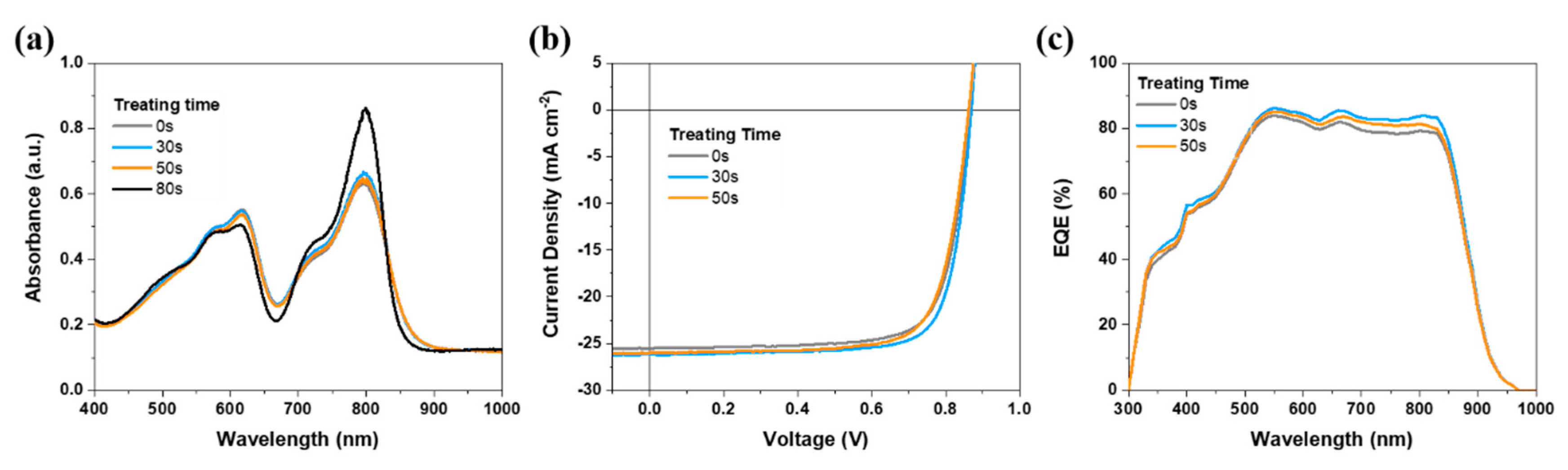
| PM6:SY1 | VOC (V) | JSC (mA cm−2) | FF (%) | PCE (%) |
|---|---|---|---|---|
| SVA 0 s | 0.865 | 25.49/25.89 | 75.7 | 16.69 (16.44 ± 0.17) |
| SVA 30 s | 0.869 | 26.14/25.93 | 77.4 | 17.57 (17.30 ± 0.20) |
| SVA 50 s | 0.862 | 25.97/25.40 | 75.0 | 16.80 (16.60 ± 0.10) |
| SVA 80 s | 0.857 | 25.06/24.63 | 72.2 | 15.51 |
Publisher’s Note: MDPI stays neutral with regard to jurisdictional claims in published maps and institutional affiliations. |
© 2022 by the authors. Licensee MDPI, Basel, Switzerland. This article is an open access article distributed under the terms and conditions of the Creative Commons Attribution (CC BY) license (https://creativecommons.org/licenses/by/4.0/).
Share and Cite
Hou, Y.; Wang, Q.; Huang, C.; Yang, T.; Shi, S.; Yao, S.; Ren, D.; Liu, T.; Zhang, G.; Zou, B. Controlling the Treatment Time for Ideal Morphology towards Efficient Organic Solar Cells. Molecules 2022, 27, 5713. https://doi.org/10.3390/molecules27175713
Hou Y, Wang Q, Huang C, Yang T, Shi S, Yao S, Ren D, Liu T, Zhang G, Zou B. Controlling the Treatment Time for Ideal Morphology towards Efficient Organic Solar Cells. Molecules. 2022; 27(17):5713. https://doi.org/10.3390/molecules27175713
Chicago/Turabian StyleHou, Yiwen, Qiuning Wang, Ciyuan Huang, Tao Yang, Shasha Shi, Shangfei Yao, Donglou Ren, Tao Liu, Guangye Zhang, and Bingsuo Zou. 2022. "Controlling the Treatment Time for Ideal Morphology towards Efficient Organic Solar Cells" Molecules 27, no. 17: 5713. https://doi.org/10.3390/molecules27175713
APA StyleHou, Y., Wang, Q., Huang, C., Yang, T., Shi, S., Yao, S., Ren, D., Liu, T., Zhang, G., & Zou, B. (2022). Controlling the Treatment Time for Ideal Morphology towards Efficient Organic Solar Cells. Molecules, 27(17), 5713. https://doi.org/10.3390/molecules27175713