Article

Unusual Spin Exchanges Mediated by the Molecular Anion P2S64−: Theoretical Analyses of the Magnetic Ground States, Magnetic Anisotropy and Spin Exchanges of MPS3 (M = Mn, Fe, Co, Ni)

1
Department of Chemistry and Research Institute for Basic Sciences, Kyung Hee University, Seoul 02447, Korea
2
Max Planck Institute for Solid State Research, Heisenbergstrasse 1, D-70569 Stuttgart, Germany
3
Department of Chemistry, North Carolina State University, Raleigh, NC 27695-8204, USA
*
Authors to whom correspondence should be addressed.
Molecules 2021, 26(5), 1410; https://doi.org/10.3390/molecules26051410
Submission received: 27 January 2021 / Revised: 24 February 2021 / Accepted: 26 February 2021 / Published: 5 March 2021

Abstract

:
We examined the magnetic ground states, the preferred spin orientations and the spin exchanges of four layered phases MPS3 (M = Mn, Fe, Co, Ni) by first principles density functional theory plus onsite repulsion (DFT + U) calculations. The magnetic ground states predicted for MPS3 by DFT + U calculations using their optimized crystal structures are in agreement with experiment for M = Mn, Co and Ni, but not for FePS3. DFT + U calculations including spin-orbit coupling correctly predict the observed spin orientations for FePS3, CoPS3 and NiPS3, but not for MnPS3. Further analyses suggest that the ||z spin direction observed for the Mn2+ ions of MnPS3 is caused by the magnetic dipole–dipole interaction in its magnetic ground state. Noting that the spin exchanges are determined by the ligand p-orbital tails of magnetic orbitals, we formulated qualitative rules governing spin exchanges as the guidelines for discussing and estimating the spin exchanges of magnetic solids. Use of these rules allowed us to recognize several unusual exchanges of MPS3, which are mediated by the symmetry-adapted group orbitals of P2S64− and exhibit unusual features unknown from other types of spin exchanges.

1. Introduction

In an extended solid, transition-metal magnetic cations M are surrounded by main-group ligands L to form MLn (typically, n = 3–6) polyhedra, and the unpaired spins of M are accommodated in the singly occupied d-states (i.e., the magnetic orbitals) of MLn. Each d-state has the metal d-orbital combined out-of-phase with the p-orbitals of the surrounding ligands L. The tendency for two adjacent magnetic ions to have a ferromagnetic (FM) or an antiferromagnetic (AFM) spin alignment is determined by the spin exchange between them, which takes place through the M-L-M or M-L…L-M exchange path [1,2,3,4]. Whereas the characteristics (e.g., the angular and distance dependence) of the M-L-M exchanges is conceptually well understood [5,6,7,8], the properties of the M-L…L-M exchanges involving several main-group ligands have only come into focus in the last two decades [1,2,3,4]. Furthermore, the character of a M-L…L-M exchange can be modified if the L…L contact is bridged by a d0 metal cation A to form a L…A…L bridge [1,2,3,4]. What has not been well understood so far is the M-L…L-M exchange in which the L…L contact is an integral part of the covalent framework of a molecular anion made up of main group elements (e.g., the P2S64− anion in MPS3, where M = Mn, Fe, Co, Ni), which might be termed the M-(L-L)-M exchange to emphasize its difference from the M-L-M, M-L…L-M and M-L…A…L-M exchanges.
In the present work we examine the M-(L-L)-M spin exchanges in the layered phases MPS3 (M = Mn [9,10,11], Fe [9,10,11], Co [10,11], Ni [10,11]), which crystallize with a monoclinic structure (space group C2/m, no. 12). Each layer of MPS3 is made up of the molecular anions P2S64− possessing the structure of staggered ethane (i.e., a trigonal antiprism structure) (Figure 1a,b). The molecular anions P2S64− form a trigonal layer (Figure 1c) with the P-P bonds perpendicular to the layer, and a high-spin M2+ cation occupies every S6 octahedral site (deviations from a trigonal symmetry caused by the monoclinic distortions are less than 1°). Thus, each MPS3 layer consists of a honeycomb arrangement of M2+ cations. With the c*-direction of the MPS3 taken as the z-direction, the P-P bond of each P2S64− is parallel to the z-direction (||z), and each MS6 octahedron is arranged with one of its three-fold rotational axes along the ||z-direction.
To a first approximation, it may be assumed that each MPS3 layer has a trigonal symmetry (see below for further discussion), so there are three types of spin exchanges to consider, i.e., the first nearest-neighbor (NN) spin exchange J12, the second NN spin exchange J13, and the third NN exchange J14 (Figure 1d). J12 is a spin exchange of the M-L-M type, in which the two metal ions share a common ligand, while J13 and J14 are nominally spin exchanges of the M-L…L-M type, in which the two metal ions do not share a common ligand. In describing the magnetic properties of MPS3 in terms of the spin exchanges J12, J13 and J14, an interesting conceptual problem arises. Each P2S64− anion is coordinated to the six surrounding M2+ cations simultaneously (Figure 1c,d), so one P2S64− anion participates in all three different types of spin exchanges simultaneously with the surrounding six M2+ ions. Furthermore, the lone-pair orbitals of the S atoms of P2S64−, responsible for the coordination with M2+ ions, form symmetry-adapted group orbitals, in which all six S atoms participate (for example, see Figure 1e). Consequently, there is no qualitative argument with which to even guess the possible differences in J12, J13, and J14. Over the past two decades, it became almost routine to quantitatively determine any spin exchanges of a magnetic solid by performing an energy-mapping analysis based on first principles DFT calculations. From a conceptual point of view, it would be very useful to have qualitative rules with which to judge whether the spin exchange paths involving complex intermediates are usual or unusual.
A number of experimental studies examined the magnetic properties of MPS3 (M = Mn [9,11,12,13,14], Fe [9,11,15,16,17,18], Co [11,19], Ni [11,20]). The magnetic properties of MPS3 (M = Mn, Fe, Co, Ni) monolayers were examined by DFT calculations to find their potential use as single-layer materials possessing magnetic order [21]. The present work is focused on the magnetic properties of bulk MPS3. For the ordered AFM states of MPS3, the neutron diffraction studies reported that the layers of MnPS3 exhibits a honeycomb-type AFM spin arrangement, AF1 (Figure 2a), but those of FePS3, CoPS3 and NiPS3 a zigzag-chain spin array, AF2 (Figure 2b), in which the FM chains running along the a-direction are antiferromagnetically coupled (hereafter, the ||a-chain arrangement). An alternative AFM arrangement, AF3 (Figure 2c), in which the FM zigzag chains running along the (a + b)-direction are antiferromagnetically coupled (hereafter, the ||(a + b)-chain arrangement), is quite similar in nature to the ||a-chain arrangement.
At present, it is unclear why the spin arrangement of MnPS3 differs from those of FePS3, CoPS3 and NiPS3 and why FePS3, CoPS3 and NiPS3 all adopt the ||a-chain arrangement rather than the ||(a + b)-chain arrangement. To explore these questions, it is necessary to examine the relative stabilities of a number of possible ordered spin arrangements of MPS3 (M = Mn, Fe, Co, Ni) by electronic structure calculations and analyze the spin exchanges of their spin lattices.
Other quantities of importance for the magnetic ions M of an extended solid are the preferred orientations of their magnetic moments with respect to the local coordinates of the MLn polyhedra. These quantities, i.e., the magnetic anisotropy energies, are also readily determined by DFT calculations including spin orbit coupling (SOC). For the purpose of interpreting the results of these calculations, the selection rules for the preferred spin orientation of MLn were formulated [2,3,22,23,24] based on the SOC-induced interactions between the highest-occupied molecular orbital (HOMO) and lowest-unoccupied molecular orbital (LUMO) of MLn. With the local z-axis of MLn taken along its n-fold rotational axis (n = 3, 4), the quantity needed for the selection rules is the minimum difference, |ΔLz|, in the magnetic quantum numbers Lz of the d-states describing the angular behaviors of the HOMO and LUMO. It is of interest to analyze the preferred spin orientations of the M2+ ions in MPS3 (M = Mn, Fe, Co, Ni) from the viewpoint of the selection rules.
Our work is organized as follows: Section 2 describes simple qualitative rules governing spin exchanges. The details of our DFT calculations are presented in Section 3.1. The magnetic ground states of MPS3 (M = Mn, Fe, Co, Ni) are discussed in Section 3.2, the preferred spin orientations of M2+ ions of MPS3 in Section 3.3, and the quantitative values of the spin exchanges determined for MPS3 in Section 3.4. We analyze the unusual features of the calculated spin exchanges via the P2S64− anion in Section 3.5, and investigate in Section 3.6 the consequences of the simplifying assumption that the honeycomb spin lattice has a trigonal symmetry rather than a slight monoclinic distortion found experimentally. Our concluding remarks are summarized in Section 4.

2. Qualitative Rules Governing Spin Exchanges

2.1. Spin Exchange between Magnetic Orbitals

For clarity, we use the notation ( φ i , φ j ) to represent the spin exchange arising from the magnetic orbitals φ i and φ j at the magnetic ion sites A and B, respectively. It is well known that ( φ i , φ j ) consists of two competing terms [1,2,3,4,25]
( φ i , φ j ) = J F + J A F
The FM component J F (>0) is proportional to the exchange repulsion,
J F K i j
which increases with increasing the overlap electron density ρ i j = φ i φ j . In case when the magnetic orbitals φ i and φ j are degenerate (e.g., between the t2g states or between eg states of the magnetic ions at octahedral sites), the AFM component JAF (<0) is proportional to the square of the energy split Δ e i j between φ i and φ j induced by the interaction between them,
J A F ( Δ e i j ) 2 ( S i j ) 2
The energy split Δ e i j is proportional to the overlap integral S i j = 〈 φ i | φ j 〉, so that the magnitude of the AFM component J A F increases with increasing that of ( S i j ) 2 . If φ i and φ j are not degenerate (e.g., between the t2g and eg states of the magnetic ions), the magnitude of J A F is approximately proportional to ( S i j ) 2 .

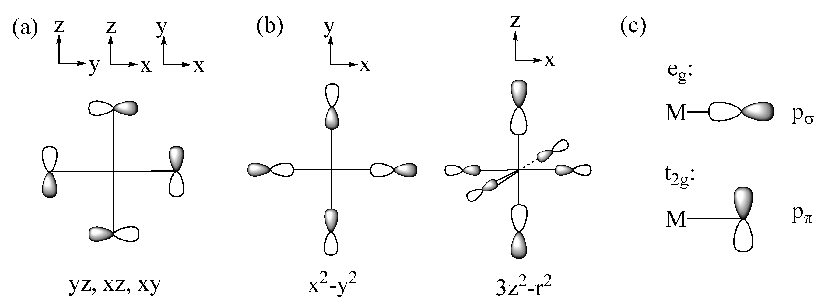
2.2. p-Orbital Tails of Magnetic Orbitals

The spin exchanges between adjacent transition-metal cations M are determined by the interactions between their magnetic orbitals, which in turn are governed largely by the overlap and the overlap electron density that are generated by the p-orbitals of the ligands present in the magnetic orbitals (the p-orbital tails, for short) [1,2,3,4]. Suppose that the metal ions M are surrounded by main-group ligands L to form ML6 octahedra. In the t2g and eg states of an ML6 octahedron (Figure 3a,b), the d-orbitals of M make σ and π antibonding combinations with the p-orbitals of the ligands L. Thus, the p-orbital tails of the t2g and eg states are represented as in Figure 4a,b, respectively, so that each M-L bond has the pπ and pσ tails in the t2g and eg states, respectively, as depicted in Figure 4c. The triple-degeneracy of the t2g and the double-degeneracy of the eg states are lifted in a ML5 square pyramid and a ML4 square plane, both of which have a four-fold rotational symmetry; the t2g states (xz, yz, xy) are split into (xz, yz) and xy, and the eg states (3z2 − r2, x2 − y2) into 3z2 − r2 and x2 − y2. Nevertheless, the description of the ligand p-orbital tails of the d-states depicted in Figure 4c remains valid.

2.3. Spin Exchanges in Terms of the p-Orbital Tails

In this section, we generalize the qualitative rules of spin exchanges formulated for the magnetic solids of Cu2+ ions [4]. Each Cu2+ ion has only one magnetic orbital, i.e., the x2−y2 state in which each Cu-L bond has a pσ tail. The d-electron configuration of the magnetic ion is (t2g↑)3(eg↑)2(t2g↓)0(eg↓)0 in MnPS3, (t2g↑)3(eg↑)2(t2g↓)1(eg↓)0 in FePS3, (t2g↑)3(eg↑)2(t2g↓)2(eg↓)0 in CoPS3, and (t2g↑)3(eg↑)2(t2g↓)3(eg↓)0 in NiPS3. Thus, the Mn2+, Fe2+, Co2+, and Ni2+ ions possess 5, 4, 3, and 2 magnetic orbitals, respectively. For magnetic ions with several magnetic orbitals, the spin exchange JAB between two such ions located at sites A and B is given by the sum of all possible individual exchanges ( φ i , φ j ) ,
J A B = 2 n A n B i A j B ( φ i , φ j ) i A j B ( φ i , φ j )
where n A and n B are the number of magnetic orbitals at the sites A and B, respectively. Each individual exchange ( φ i , φ j ) can be FM or AFM depending on which term, JF or JAF, dominates. Whether JAB is FM or AFM depends on the sum of all individual ( φ i , φ j ) contributions.

2.3.1. M-L-M Exchange

As shown in Figure 5, there occur three types of M-L-M exchanges between the magnetic orbitals of t2g and eg states.
If the M-L-M bond angle θ is 90° for the (eg, eg) and (t2g, t2g) exchanges, and also when θ is 180° for the (eg, t2g) exchange, the two p-orbital tails have an orthogonal arrangement so that 〈 φ i | φ j 〉 = 0 (i.e., J A F = 0). However, the overlap electron density φ i φ j is nonzero (i.e., J F ≠ 0), hence predicting these spin exchanges to be FM. When the θ angles of the (eg, eg) and (t2g, t2g) exchanges increase from 90° toward 180°, and also when the angle θ of the (eg, t2g) exchange decreases from 180° toward 90°, both J A F and J F are nonzero so that the balance between the two determines if the overall exchange ( φ i , φ j ) becomes FM or AFM. These trends are what the Goodenough–Kanamori rules [5,6,7,8] predict.

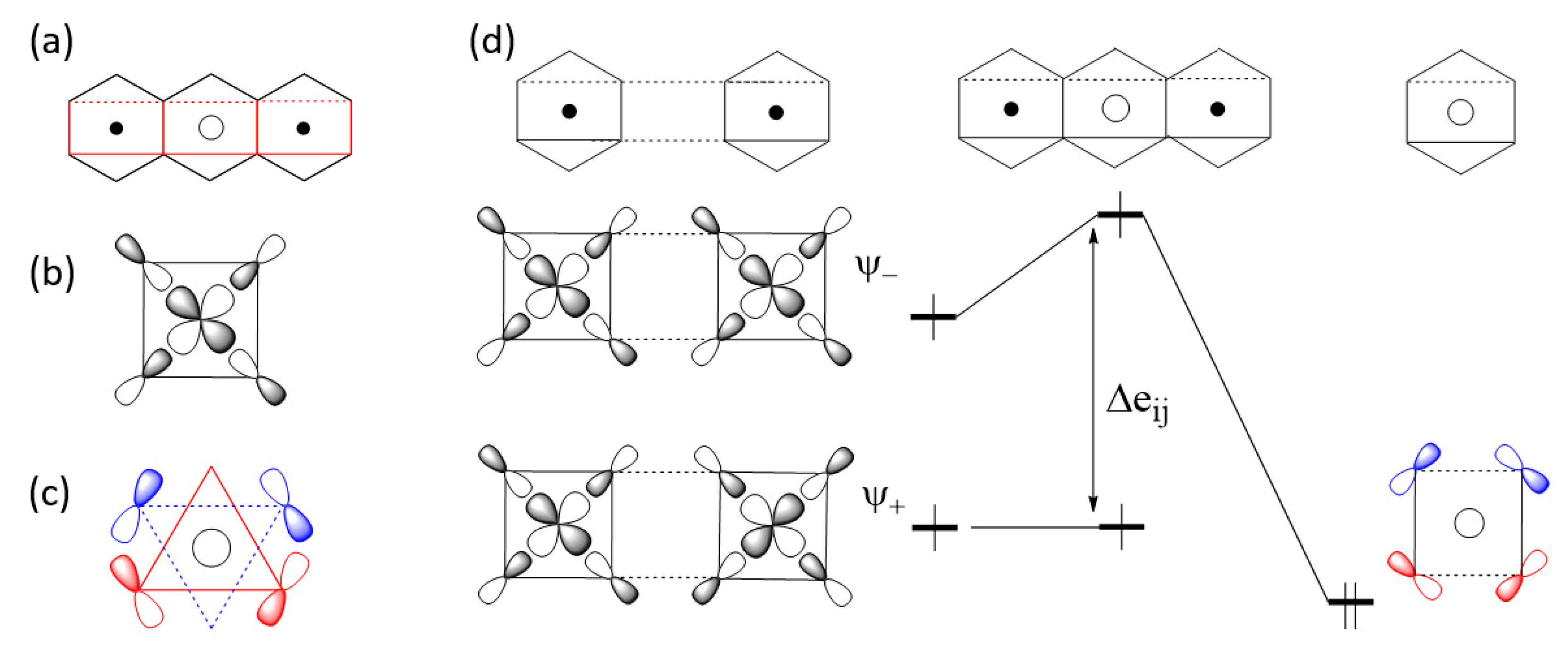
2.3.2. M-L…L-M Exchange

There are two extreme cases of M-L…L-M exchange. When the pσ-orbital tails are pointing toward each other (Figure 6a), the overlap integral, 〈 φ i | φ j 〉, can be substantial if the contact distance L…L lies in the vicinity of the van der Waals distance. However, the overlap electron density ρ i j = φ i φ j is practically zero because φ i and φ j do not have an overlapping region. Consequently, the in-phase and out-of-phase states Ψ+ and Ψ- are split in energy with a large separation Δ e i j . Thus, it is predicted that the M-L…L-M type exchange can only be AFM [1,2,3,4]. When the L…L linkage is bridged by a d0 cation such as V5+ or W6+, for example, only the out-of-phase state Ψ- is lowered in energy by the dπ orbital of the cation A, reducing the Δ e i j so that the M-L…A…L-M exchange becomes weak (Figure 6b). Conversely, when the p-orbital tails of the M-L…L-M exchange path have an orthogonal arrangement (Figure 7a), the overlap integral, 〈 φ i | φ j 〉, is zero, making the M-L…L-M exchange weak. If the L…L linkage of such an exchange path is bridged by a d0 cation, the out-of-phase state Ψ- level is lowered in energy enlarging Δ e i j so that the M-L…A…L-M becomes strongly AFM (Figure 7b) [2,3,4].
In the M-L…A…L-M exchange of Figure 7, the vanishingly small Δ e i j of the M-L…L-M exchange results because the two pσ tails have an orthogonal arrangement. A very small Δ e i j for the M-L…L-M exchange occurs even if the two M-L bonds are pointing to each other as in Figure 6 when one M-L bond has a pσ tail and the other has a pπ tail, and also when both M-L bonds have pπ tails. Such M-L…L-M spin exchanges become strong in the corresponding M-L…A…L-M exchanges.

2.3.3. Qualitative Rules Governing Spin Exchanges

The above discussions are based on the observation that the nature of a spin exchange, be it the M-L-M, M-L…L-M or M-L…A…L-M type, is governed by the ligand p-orbital tails present in the magnetic orbitals of the spin exchange path. The essential points of our discussions can be summarized as follows:
  • For an individual ( φ i , φ j ) exchange of a M-L-M type, the (t2g, t2g) and (eg, eg) exchanges are FM if the bond angle θ is 90°, and so is the (t2g, eg) exchange if the bond angle θ is 180°. These exchanges become AFM when the bond angles θ deviate considerably from these values.
  • An individual ( φ i , φ j ) exchange of a M-L…L-M or M-L…A…L-M type can only be AFM if not weak.
  • A strong individual ( φ i , φ j ) exchange of a M-L…L-M is weakened by the d0 metal cation A in the M-L…A…L-M exchange, but a weak individual ( φ i , φ j ) exchange of a M-L…L-M is strengthened by the presence of a d0 metal cation A in the M-L…A…L-M exchange.
  • When a magnetic ion has several unpaired spins, the spin exchange between two magnetic ions is given by the sum of all possible individual ( φ i , φ j ) exchanges.
These qualitative rules governing spin exchanges can serve as guidelines for exploring how the calculated spin exchanges are related to the structures of the exchange paths and also for ensuring that important exchange paths are included the set of spin exchanges to evaluate by the energy-mapping analysis.

3. Results and Discussion

3.1. Details of Calculations

We performed spin-polarized DFT calculations using the Vienna ab initio Simulation Package (VASP) [26,27], the projector augmented wave (PAW) method, and the PBE exchange-correlation functionals [28]. The electron correlation associated with the 3d states of M (M = Mn, Fe, Co, Ni) was taken into consideration by performing the DFT+U calculations [29] with the effective on-site repulsion Ueff = UJ = 4 eV on the magnetic ions. Our DFT + U calculations carried out for numerous magnetic solids of transition-metal ions showed that use of the Ueff values in the range of 3 − 5 eV correctly reproduce their magnetic properties (see the original papers cited in the review articles [1,2,3,22,24]). The primary purpose of using DFT + U calculations is to produce magnetic insulating states for magnetic solids. Use of Ueff = 3 − 5 eV in DFT + U calculations leads to magnetic insulating states for magnetic solids of Mn2+, Fe2+, Co2+, and Ni2+ ions. The present work employed the representative Ueff value of 4 eV. We carried out DFT + U calculations (with Ueff = 4 eV) to optimize the structures of MPS3 (M = Mn, Fe, Co, Ni) in their FM states by relaxing only the ion positions while keeping the cell parameters fixed and using a set of (4 × 2 × 6) k-points and the criterion of 5 × 10⁻³ eV/Å for the ionic relaxation. All our DFT + U calculations for extracting the spin-exchange parameters employed a (2a, 2b, c) supercell, the plane wave cutoff energy of 450 eV, the threshold of 10−6 eV for self-consistent-field energy convergence, and a set of (4 × 2 × 6) k-points. The preferred spin direction of the cation M2+ (M = Mn, Fe, Co, Ni) cation was determined by DFT + U + SOC calculations [30], employing a set of (4 × 2 × 6) k-points and the threshold of 10−6 eV for self-consistent-field energy convergence.

3.2. Magnetic Ground States of MPS3

We probed the magnetic ground states of the MPS3 phases by evaluating the relative energies, on the basis of DFT + U calculations, of the AF1, AF2 and AF3 spin configurations shown in Figure 2 as well as the FM, AF4, AF5, and AF6 states depicted in Supplementary Materials Figure S1. As summarized in Table 1, our calculations using the experimental structures of MPS3 show that the magnetic ground states of MnPS3 and NiPS3 adopt the honeycomb state AF1 and the ||a-chain state AF2, respectively, in agreement with experiment. In disagreement with experiment, however, the magnetic ground state is predicted to be the ||(a + b)-chain state AF3 for FePS3, and the honeycomb state AF1 for CoPS3. Since the energy differences between different spin ordered states are small, it is reasonable to speculate if they may be affected by small structural (monoclinic) distortion. Thus, we optimize the crystal structures of MPS3 (M = Mn, Fe, Co, Ni) by performing DFT + U calculations to obtain the structures presented in the supporting material. Then, we redetermined the relative stabilities of the FM and AF1–AF6 states using these optimized structures. Results of these calculations are also summarized in Table 1. The optimized structures predict that the magnetic ground states of MnPS3, CoPS3 and NiPS3 are the same as those observed experimentally, but that of FePS3 is still the ||(a+b)-chain state AF3 rather than the ||a-chain state AF2 reported experimentally. This result is not a consequence of using the specific value of Ueff = 4 eV, because our DFT + U calculations for FePS3 with Ueff = 3.5 and 4.5 eV lead to the same conclusion.
To resolve the discrepancy between theory and experiment on the magnetic ground state of FePS3, we note that the magnetic peak positions in the neutron diffraction profiles are determined by the repeat distances of the rectangular magnetic structures, namely, a and b for the AF2 state (Figure 2b), and a’ and b’ for the AF3 state (Figure 2c). In both the experimental and the optimized structures of FePS3, it was found that a = a’ = 5.947 Å and b = b’ = 10.300 Å. Thus, for the neutron diffraction refinement of the magnetic structure for FePS3, the AF2 and AF3 states provide an equally good model. In view of our computational results, we conclude that the AF3 state is the correct magnetic ground state for FePS3.
The experimental and optimized structures of MPS3 (M = Mn, Fe, Co, Ni) are very similar, as expected. The important differences between them affecting the magnetic ground state would be the M-S distances of the MS6 octahedra, because the d-state splitting of the MS6 octahedra is sensitively affected by them. The M-S distances of the MS6 octahedra taken from the experimental and optimized crystal structures of MPS3 are summarized in Table 2, and their arrangements in the honeycomb layer are schematically presented in Figure 8. All Mn-S bonds of MnS6 in MnPS3 are nearly equal in length, as expected for a high-spin d5 ion (Mn2+) environment. The Fe-S bonds of FeS6 in the optimized structure of FePS3 are grouped into two short and four long Fe-S bonds. This distinction is less clear in the experimental structure. The Co-S bonds of CoS6 in the experimental and optimized structures of CoPS3 are grouped into two short, two medium and two long Co-S bonds. However, the sequence of the medium and long Co-S bonds is switched between the two structures. In the experimental and optimized structures of NiPS3, the Ni-S bonds of NiS6 are grouped into two short, two medium and two long Ni-S bonds. This distinction is less clear in the experimental structure. Thus, between the experimental and optimized structures of MPS3, the sequence of the two short, two medium and two long M-S bonds do not switch for M = Fe and Ni whereas it does for M = Co. The latter might be the cause for why the relative stabilities of the AF1 and AF2 states in CoPS3 switches between the experimental and optimized structures.

3.3. Preferred Spin Orientation of MPS3

3.3.1. Quantitative Evaluation

We determine the preferred spin orientations of the M2+ ions in MPS3 (M = Mn, Fe, Co, Ni) phases by performing DFT + U + SOC calculations using their FM states with the ||z and ⊥z spin orientations. For the ⊥z direction we selected the ||a-direction. As summarized in Table 3, these calculations predict the preferred spin orientation to be the ||z direction for FePS3, and the ||x direction for MnPS3, CoPS3 and NiPS3. These predictions are in agreement with experiment for FePS3 [9,18], CoPS3 [19], and NiPS3 [20], while this is not the case for MnPS3 [9,12,14,31]. Our DFT + U + SOC calculations for the AF1 state of MnPS3 show that the ||x spin orientation is still favored over the ||z orientation just as found from the calculations using the FM state of MnPS3. The Mn2+ spins of MnPS3 were reported to have the ||z orientation in the early studies [9,12], but were found to be slightly tilted away from the z-axis (by 8°) [14,31]. In our further discussion (see below), this small deviation is neglected.

3.3.2. Qualitative Picture

Selection Rules of Spin Orientation and Implications

With the local z-axis of a ML6 octahedron along its three-fold rotational axis (Figure 1a), the t2g set is described by {1a, 1e’}, and the eg set by {2e’}[22,23,24], where
1 a = 3 z 2 r 2 { 1 e } = { 2 3 x y 1 3 x z , 2 3 ( x 2 y 2 ) 1 3 y z } { 2 e } = { 1 3 x y + 2 3 x z , 1 3 ( x 2 y 2 ) + 2 3 y z }
Using these d-states, the electron configurations expected for the M2+ ions of MPS3 (M = Mn, Fe, Co, Ni) are presented in Figure 9. In the spin polarized description of a magnetic ion, the up-spin d-states lie lower in energy than the down-spin states so that the HOMO and LUMO occur in the down-spin d-states for the M2+ ions with more than the d5 electron count, so only the down-spin states are shown for FePS3, CoPS3, and NiPS3 in Figure 9a–c. For MnPS3 with d5 Mn2+ ion, the HOMO is represented by the up-spin 1e’, and the LUMO by the down-spin 1a and 2e’ (Figure 9d).
In terms of the d-orbital angular states |L, Lz〉 (L = 2, Lz = −2, −1, 0, 1, 2), the 1e’ state consists of the |2, ±2〉 and |2, ±1〉 sets in the weight ratio of 2:1, and the 2e’ state in the weight ratio of 1:2 ratio. Consequently, the major component of the 1e’ set is the |2, ±2〉 set, while that of the 2e’ set is the |2, ±1〉 set.
The selection rules of the spin orientation are based on the |ΔLz| value between the HOMO and LUMO of MLn. If the HOMO and LUMO both occur in the up-spin state or in down-spin states (Figure 9a–c), the ||z spin orientation is predicted if |ΔLz| = 0, and the ⊥z spin orientation if |ΔLz| = 1. When |ΔLz| > 1, the HOMO and LUMO do not interact under SOC and hence do not affect the spin orientation. Between the 1a, 1e’ and 2e’ states, we note the following cases of values:
| Δ L z | = 0 { between   the   major   components   of   the   1 e   set between   the   major   components   of   the   2 e   set
| Δ L z | = 1 { between   1a   and   the   minor   component   of   1 e between   1a   and   the   major   component   of   2 e between   the   major   components   of   1 e   and   2 e
We now examine the preferred spin orientations of MPS3 from the viewpoint of the selection rules and their electron configurations (Figure 9). The d-electron configuration of FePS3 can be either (d↑)5(1e’↓)1 or (d↑)5(1a↓)1 (Figure 9a), where the notation (d↑)5 indicates that all up-spin d-states are occupied. The (d↑)5(1e’↓)1 configuration, for which |ΔLz| = 0, predicts the ||z spin orientation, while the (d↑)5(1a↓)1 configuration, for which |ΔLz| = 1, predicts the ⊥z spin orientation. Thus, the (d↑)5(1a↓)1 configuration is correct for the Fe2+ ion of FePS3. Since this configuration has the degenerate level 1e’ unevenly occupied, it should possess uniaxial magnetism [2,3,22,23,24] and hence a large magnetic anisotropy energy. This is in support of the experimental finding of the Ising character of the spin lattice of FePS3 [16] or the single-ion anisotropic character of the Fe2+ ion [17,18]. The d-electron configuration of CoPS3 can be either (d↑)5(1e’↓)2 or (d↑)5(1a↓)1(1e’↓)1 (Figure 9b). The (d↑)5(1e’↓)2 configuration, for which |ΔLz| = 1, predicts the ⊥z spin orientation, while the (d↑)5(1a↓)1(1e’↓)1 configuration, for which |ΔLz| = 0, predicts the ||z spin orientation. Thus, the (d↑)5(1e’↓)2 configuration is correct for the Co2+ ion of CoPS3. Since this configuration has the degenerate level 1e’ evenly occupied, it does not possess uniaxial magnetism [2,3,22,23,24] and hence a small magnetic anisotropy energy. The d-electron configuration of NiPS3 is given by (d↑)5(1a)1(1e’↓)2 (Figure 9c), for which |ΔLz| = 1, so the ⊥z spin orientation is predicted in agreement with experiment.
Let us now consider the spin orientation of the Mn2+ ion of MnPS3. First, it should be noted that, if the HOMO and LUMO occur in different spin states as in MnPS3 (Figure 9d), the selection rules predict the opposite to those found for the case when the HOMO and LUMO occur all in up-spin states or all in down-spin states [2,3,22,23,24]. Namely, the preferred spin orientation is the ||z spin orientation if |ΔLz| = 1, but the ⊥z spin orientation if |ΔLz| = 0 [2,3,22,23,24]. According to Equation (7), |ΔLz| = 1 for the Mn2+ ion of MnPS3, which predicts the ⊥z orientation as the preferred spin direction in agreement with the quantitative estimate of the magnetic anisotropy energy obtained from the DFT + U + SOC calculations, although this is in disagreement with experiment [5,8,9,10]. It has been suggested that the ||z spin orientation is caused by the magnetic dipole–dipole (MDD) interactions [13]. This subject will be probed in the following.

Magnetic Dipole–Dipole Interactions

Being of the order of 0.01 meV for two spin-1/2 ions separated by 2 Å, the MDD interaction is generally weak. For two spins located at sites i and j with the distance rij and the unit vector eij along the distance, the MDD interaction is defined as [32]
( g 2 μ B 2 a 0 3 ) ( a 0 r i j ) 3 [ 3 ( S i e i j ) ( S j e i j )   + ( S i S j ) ]
where a0 is the Bohr radius (0.529177 Å), and (gμB)2/(a0)3 = 0.725 meV. The MDD effect on the preferred spin orientation of a given magnetic solid can be examined by comparing the MDD interaction energies calculated for a number of ordered spin arrangements. In summing the MDD interactions between various pairs of spin sites, it is necessary to employ the Ewald summation method [33,34,35]. Table 4 summarizes the MDD interaction energies calculated, by using the optimized structures of MPS3 (M = Mn, Fe, Co, Ni), for the ||z and ||x spin directions in the AF1, AF2 and AF3 states. The corresponding results obtained by using the experimental structures of MPS3 are summarized in Table S1.
These results can be summarized as follows: for the ||z spin orientation, the AF1 state is more stable than the AF2 and AF3 states. For the ||x spin orientation, the AF2 state is more stable than the AF1 and AF3 states. The ||x spin direction of the AF2 state is more stable than the ||z spin direction of the AF1 state. However, none of these results can reverse the relative stabilities of the ||z and ||x spin directions determined for FePS3, CoPS3, and NiPS3 from the DFT + U + SOC calculations (Table 3). The situation is slightly different for MnPS3, which adopts the AF1 state as the magnetic ground state. For MnPS3 in this state, the MDD calculations predict that the ||z spin orientation is more stable than the ||x spin orientation by 0.3 K per formula unit (Table 4). Note that this prediction is the exact opposite to what the DFT + U + SOC calculations predict for MnPS3 in the AF1 state (Table 3). Thus, the balance between these two opposing energy contributions will determine whether the ||z spin orientation is more stable than the ⊥z spin orientation in agreement with the experimental observation. Consequently, for MnPS3 the MDD interaction dominates over the SOC effect which is plausible because of the half-filled shell electronic configuration. This is because the AF1 magnetic structure is forced on MnPS3; in terms of purely MDD interactions alone, the ⊥z spin orientation in the AF2 state is most stable.

3.4. Quantitative Evaluations of Spin Exchanges

Due to the monoclinic crystal structure that MPS3 adopts, each of the exchanges J12, J13 and J14 (Figure 10a) are expected to split into two slightly different spin exchanges (Figure 10b) so that there are six spin exchanges J1–J6 to consider. To extract the values of the six spin exchanges J1–J6 (Figure 3), we employ the spin Hamiltonian expressed as:
H s p i n = i > j J i j S ^ i S ^ j
Then, the energies of the FM and AF1–AF6 states of MPS3 (M = Mn, Fe, Co, Ni) per 2 × 2 × 1 supercell are written as:
EFM = (–16J1 − 8J2 − 16J3 − 32J4 − 16J5 − 8J6)S2
     EAF1 = (+16J1 + 8J2 − 16J3 − 32J4 + 16J5 + 8J6)S2
     EAF2 = (−16J1 + 8J2 − 16J3 + 32J4 + 16J5 + 8J6)S2
EAF3 = (−8J2 + 16J3 + 16J5 + 8J6)S2      
     EAF4 = (+16J1 − 8J2 − 16J3 + 32J4 − 16J5 − 8J6)S2
EAF5 = (+8J2 + 16J3 − 16J5 + 8J6)S2      
EAF6 = (−8J2 + 16J3 + 16J5 − 8J6)S2      
where S is the spin on each M2+ ion (i.e., S = 5/2, 2, 3/2 and 1 for M = Mn, Fe, Co, and Ni, respectively). By mapping the relative energies of the FM and AF1–AF6 states determined in terms of the spin exchange J1–J6 onto the corresponding relative energies obtained from the DFT + U calculations (Table 1), we find the values of J1–J6 listed in Table 5. (The spin exchanges of MPS3 determined by using their experimental crystal structures are summarized in Table S2)
With the sign convention adopted in Eq. 1, AFM exchanges are represented by Jij < 0, and FM exchanges by Jij > 0. From Table 5, the following can be observed:
  • In all MPS3 (M = Mn, Fe, Co, Ni), J1 ≠ J2, J3 ≠ J4, and J5 ≠ J6, reflecting that the exchange paths are different between J1 and J2, between J3 and J4, and between J5 and J6 (Figure 10).
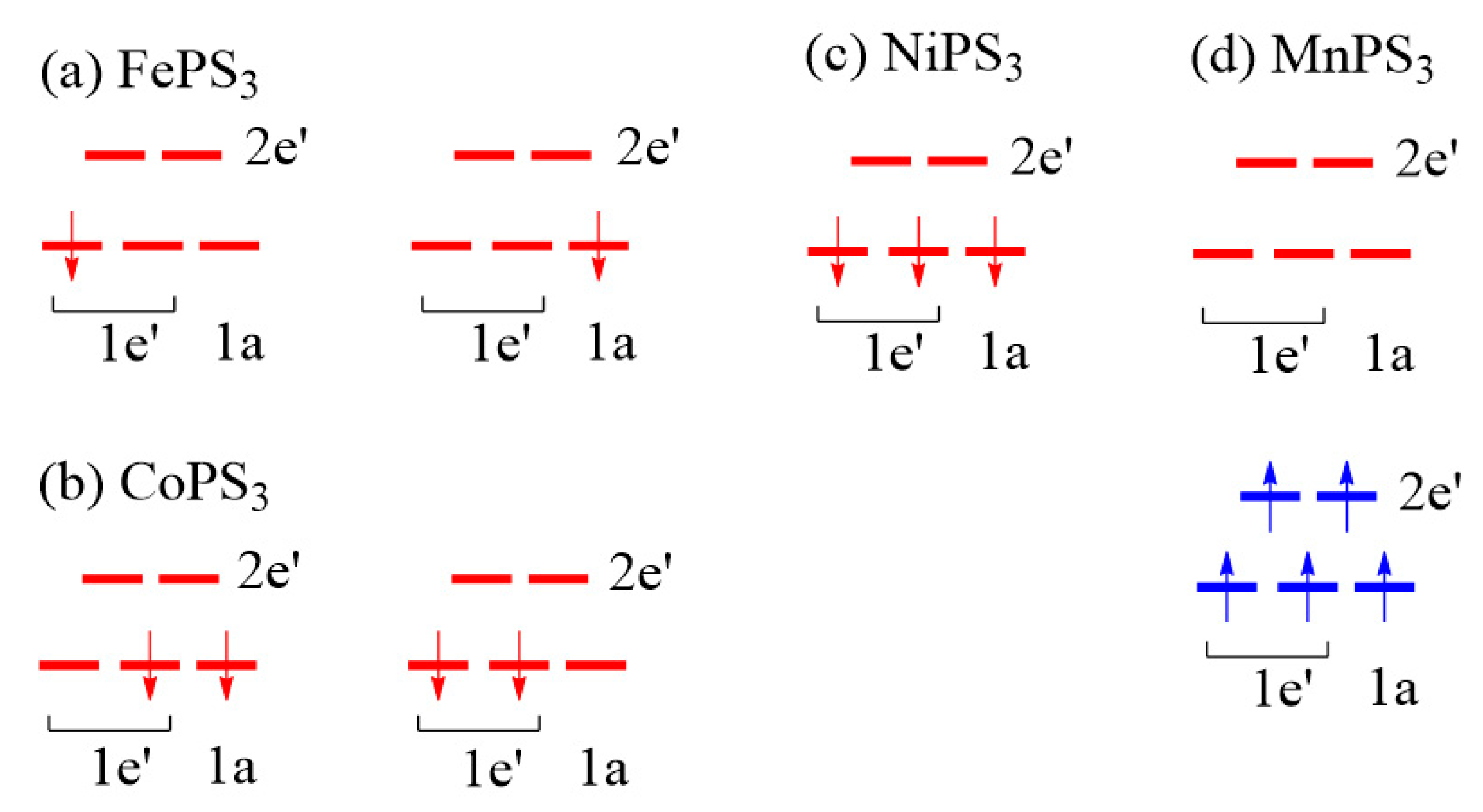
  • J1 ≈ J2 < 0, J3 ≈ J4 ≈ 0, and J5 ≈ J6 < 0 for MnPS3 while J1 ≈ J2 > 0, J3 ≈ J4 ≈ 0, and J5 ≈ J6 < 0 NiPS3. To a first approximation, the electron configurations of MnPS3 and NiPS3 can be described by (t2g)3(eg)2 and (t2g)6(eg)2, respectively. That is, they do not possess an unevenly occupied degenerate state t2g.
  • In FePS3 and CoPS3, J1 and J2 are quite different, and so are J3 and J4. While J5 and J6 are comparable in FePS3, they are quite different in CoPS3. The electron configurations of FePS3 and NiPS3 can be approximated by (t2g)4(eg)2 and (t2g)5(eg)2, respectively. Namely, they possess an unevenly occupied degenerate state t2g.
  • The strongest exchange is J1 in MnPS3, but J6 in other MPS3 (M = Fe, Co, Ni).
  • The second NN exchange J3 is strongly FM in CoPS3, while the third NN exchange J6 is very strongly AFM in CoPS3 and NiPS3.
From the viewpoints of the expected trends in spin exchanges, the observation (e) is quite unusual. This will be discussed in the next section.

3.5. Unusual Features of the M-L…L-M Spin Exchanges

3.5.1. Second Nearest-Neighbor Exchange

As pointed out in the previous section, the second NN exchange J3 of CoPS3 is strongly FM despite that it is a M-L…L-M exchange to a first approximation. This implies that the JF component in some ( φ i , φ j ) exchanges is nonzero, namely, the overlap electron density associated with those exchanges is nonzero. This implies that the p-orbital tails of the two magnetic orbitals are hybridized with the group orbitals of the P2S64− anion, i.e., they become delocalized into the whole P2S64− anion. Each MS6 octahedron has three mutually orthogonal “MS4 square planes” containing the yz, xz and xy states (Figure 11a). At the four corners of these three square planes, the p-orbital tails of the d-states are present (Figure 3a).
The lone-pair orbitals of the S atoms are important for the formation of each MS6 octahedron. Due to the bonding requirement of the P2S64− anion, such lone pair orbitals become symmetry-adapted. An example in which the p-orbitals of all the S atoms are present is shown in Figure 1e.
With the (t2g)5(eg)2 configuration, the Co2+ ion of CoPS3 has five electrons in the t2g level, namely, it has only one t2g magnetic orbital. This magnetic orbital is contained in one of the three CoS4 square planes presented in Figure 11b–d. When the S p-orbital at one corner of the P2S64− anion interacts with a d-orbital of M, the S p-orbitals at the remaining corners are also mixed in. Thus, when P2S64− anion shares corners with both MS4 square planes of the J3 exchange path, a nonzero overlap electron density is generated, thereby making the spin exchange FM. For convenience, we assume that the magnetic t2g orbital of the Co2+ ion is the xy state. Then, there will be not only the (xy, xy) exchange, but also the (xy, x2−y2) and (x2−y2, xy) exchanges between the two Co2+ ions of the J3 path. All these individual exchanges lead to nonzero overlap electron densities by the delocalization of the p-orbital tails with the group orbitals of the molecular anion P2S64−. In other words, the spin exchange J3 in CoPS3 is nominally a M-L…L-M, which is expected to be AFM by the qualitative rule, but it is strongly FM. It is clear that, if the L…L linkage is a part of the covalent framework of a molecular anion such as P2S64−, a nominal M-L…L-M exchange can become FM for a certain combination of the d-electron count of the metal M and the geometries of the exchange path.

3.5.2. Third Nearest-Neighbor Exchange

Unlike in MnPS3 and FePS3, the M-S…S-M exchange J6 is unusually strong in CoPS3 and NiPS3 (Section 3.3). This is so despite that the S…S contact distances are longer in CoPS3 and NiPS3 than in MnPS3 and FePS3 (i.e., the S…S contact distance of the J6 path in MPS3 is 3.409, 3.416, 3.421 and 3.450 Å for M = Mn, Fe, Co and Ni, respectively). We note that a strong M-L…L-M exchange (i.e., a spin exchange leading to a large energy split Δ e i j ) becomes weak, when the L…L contact is bridged by a d0 cation like, e. g., V5+ and W6+ to form the M-L…A…L-M exchange path (Figure 6b), because the out-of-phase combination ψ is lowered in energy by interacting with the unoccupied dπ orbital of the cation A. Conversely, then, one may ask if the strength of a M-L…L-M spin exchange can be enhanced by raising the ψ level. The latter can be achieved if the L…L path provides an occupied level of π-symmetry that can interact with ψ . As depicted in Figure 12a, the J6 path has the two MS4 square planes containing the x2-y2 magnetic orbitals (Figure 12b). The lone-pair group orbital of the S4 rectangular plane (Figure 12c) of the P2S64− anion has the correct symmetry to interact with ψ , so that the ψ level is raised in energy thereby enlarging the energy split between ψ + and ψ and strengthening the J6 exchange (Figure 12d). Although this reasoning applies equally to MnPS3 and FePS3, the latter do not have a strong J6 exchange. This can be understood by considering Equation (1), which shows that a magnetic ion with several magnetic orbitals leads to several individual spin exchanges that can lead to FM contributions.
In view of the above discussion, which highlights the unusual nature of the second and third NN spin exchanges mediated by a molecular anion such as P2S64−, we propose to use the notation M-(L-L)-M to distinguish it from M-L-M. M-L…L-M and M-L…A…L-M type exchanges. The notation (L-L) indicates two different ligand sites of a multidentate molecular anion, each with lone pairs for the coordination with a cation M. Such M-(L-L)-M exchanges can be strongly FM or strongly AFM, as discussed above. Currently, there are no qualitative rules with which to predict whether they will be FM or AFM. A similar situation was found, for example, for the mineral Azurite Cu3(CO3)2(OH)2, in which every molecular anion CO32− participates in three different Cu-(O-O)-Cu exchanges. DFT + U calculations show that one of these three is substantially AFM, but the remaining two are negligible. So far, this observation has not been understood in terms of qualitative reasoning.

3.6. Description Using Three Exchanges

Experimentally, the magnetic properties of MPS3 have been interpreted in terms of three exchange parameters, namely, by assuming that J1 = J2 (≡ J12), J3 = J4 (≡ J13), and J5 = J6 (≡ J14). To investigate whether this simplified description is justified, we simulate the relative energies of the seven ordered spin states of MPS3 by using the three exchanges J12, J13 and J14 as parameters in terms of the least-square fitting analysis. Our results, summarized in Table 6, show that the standard deviations of J12, J13 and J14 are small for MnPS3 and NiPS3, moderate in FePS3, but extremely large in CoPS3 (for details, see Figures S2–S5). The exchanges experimentally deduced for FePS3 are J12 = −17 K, J13 = −0.5 K, and J14 = 7 K from neutron inelastic scattering measurements [17], −17 K ≤ J12 ≤ −5.6 K, −7.2 K ≤ J13 ≤ 2.8 K, and 0 ≤ J14 ≤ 10 K from powder susceptibility measurements [9], and J12 = −19.6 K, J13 = 10.3 K, and J14 = −2.2 K from high field measurements [17]. These experimental estimates are dominated by J12, but the theoretical estimates of Table 6 by J14. One might note from Table 6 that the magnetic properties of MnPS3, FePS3 and NiPS3 can be reasonably well approximated by two exchanges, that is, by J12 and J14 for MnPS3, by J14 and J12 for NiPS3, and by J14 and J13 for FePS3. However, this three-parameter description leads to erroneous predictions for the magnetic ground states of MPS3; it predicts the AF1 state to be the ground state for both MnPS3 and CoPS3. This prediction is correct for MnPS3, but incorrect for CoPS3. In addition, it predicts that the AF2 and AF3 states possess the same stability for all MPS3 (M = Mn, Fe, Co, Ni), and are the ground states for FePS3 and NiPS3. These two predictions are both incorrect.

4. Concluding Remarks

Our DFT + U calculations for the optimized structures of MPS3 (M = Mn, Fe, Co, Ni) reveal that, in agreement with experiment, the magnetic ground state of MnPS3 is the AF1 state while those of CoPS3 and NiPS3 are the AF2 state. In disagreement with experiment, however, our calculations predict the AF2 state to be the magnetic ground state for FePS3. Our DFT + U + SOC calculations show that, in agreement with experiment, the preferred spin orientation of FePS3 is the ||z direction while those of CoPS3 and NiPS3 are the ⊥z direction, and the Fe2+ ion of FePS3 exhibits uniaxial anisotropy. In disagreement with experiment, these calculations predict the preferred spin orientation for MnPS3 to be the ⊥z direction. Our analyses suggest that the ||z spin direction experimentally observed for the Mn2+ ions arises from the magnetic dipole–dipole interactions in the AF1 magnetic state. We presented simple qualitative rules governing spin exchanges to be used as guidelines for gauging the nature of various spin exchanges. These rules allowed us to recognize several unusual exchanges of MPS3; the second NN exchange J3 of CoPS3 is strongly FM while the third NN exchanges J6 of CoPS3 and NiPS3 are very strongly AFM. These observations reflect the fact that the lone-pair orbitals of the P2S64− ion, mediating the spin exchanges in MPS3 are symmetry-adapted group orbitals, so the effect of coordinating one S atom to one M2+ ion is felt by all the remaining five S atoms of P2S64−. The spin exchanges mediated by molecular anions, termed the M-(L-L)-M type exchanges, differ in nature from the M-L-M, M-L…L-M and M-L…A…L-M type exchanges. To find qualitative trends in the M-(L-L)-M type exchanges, it is necessary to further study the spin exchanges involving various other molecular anions.

Supplementary Materials

The following are available online. Figure S1: Ordered spin states, FM, AF4, AF5 and AF6 employed together with the states AF1, AF2 and AF3 (see the text) to determine the magnetic ground states as well as the spin exchanges J1–J6 of MPS3 (M = Mn, Fe, Co, Ni). Figure S2–S5. Results of the least-square fitting the relative energies of the seven ordered spin states (FM, AF1-AF6) of MnPS3, CoPS3 and FePS3, and NiPS3, Table S1: Relative energies (in K per formula unit) of the ||x and ||z spin orientations obtained by MDD calculations for the M2+ ions of MPS3 (M = Mn, Fe, Co, Ni) in the AFM1, AF2 and AFM3 states using the experimental crystal structures. Table S2: Spin exchanges (in K) obtained for the experimental structures of MPS3 (M = Mn, Fe, Co, Ni) from DFT + U calculations with Ueff = 4 eV.

Author Contributions

Conceptualization, M.-H.W.; formal analysis and investigation, H.-J.K., R.K. and M.-H.W.; resources, H.-J.K.; data curation, H.-J.K.; writing—original draft preparation, M.-H.W.; writing—review and editing, H.-J.K., R.K. and M.-H.W.; visualization, M.-H.W.; supervision, M.-H.W.; funding acquisition, H.-J.K. All authors have read and agreed to the published version of the manuscript.

Funding

The work at Kyung Hee University was supported by the Basic Science Research Program through the National Research Foundation of Korea (NRFK) funded by the Ministry of Education (2020R1A6A1A03048004).

Institutional Review Board Statement

Not applicable.

Informed Consent Statement

Not applicable.

Acknowledgments

H.-J. K. thanks the NRFK for the fund 2020R1A6A1A03048004.

Conflicts of Interest

The authors declare no conflict of interest.

References

  1. Whangbo, M.-H.; Koo, H.-J.; Dai, D. Spin exchange interactions and magnetic structures of extended magnetic solids with localized spins: Theoretical descriptions on formal, quantitative and qualitative levels. J. Solid State Chem. 2003, 176, 417–481. [Google Scholar] [CrossRef]
  2. Xiang, H.J.; Lee, C.; Koo, H.-J.; Gong, X.; Whangbo, M.-H. Magnetic properties and energy-mapping analysis. Dalton Trans. 2013, 42, 823–853. [Google Scholar] [CrossRef]
  3. Whangbo, M.-H.; Xiang, H.J. Magnetic Properties from the Perspectives of Electronic Hamiltonian: Spin Exchange Parameters, Spin Orientation and Spin-Half Misconception. In Handbook in Solid State Chemistry, Volume 5: Theoretical Descriptions; Wiley: New York, NY, USA, 2017; pp. 285–343. [Google Scholar]
  4. Whangbo, M.-H.; Koo, H.-J.; Kremer, R.K. Spin Exchanges Between Transition-Metal Ions Governed by the Ligand p-Orbitals in Their Magnetic Orbitals. Molecules 2021, 26, 531. [Google Scholar] [CrossRef]
  5. Goodenough, J.B.; Loeb, A.L. Theory of ionic ordering, crystal distortion, and magnetic exchange due to covalent forces in spinels. Phys. Rev. 1955, 98, 391–408. [Google Scholar] [CrossRef]
  6. Goodenough, J.B. Theory of the role of covalence in the perovskite-type manganites [La, M(II)]MnO3. Phys. Rev. 1955, 100, 564–573. [Google Scholar] [CrossRef] [Green Version]
  7. Kanamori, J. Superexchange interaction and symmetry properties of electron orbitals. J. Phys. Chem. Solids 1959, 10, 87–98. [Google Scholar] [CrossRef]
  8. Goodenough, J.B. Magnetism and the Chemical Bond; Interscience; Wiley: New York, NY, USA, 1963. [Google Scholar]
  9. Kurosawa, K.; Saito, S.; Yamaguchi, Y. Neutron diffraction study on MnPS3 and FePS3. J. Phys. Soc. Jpn. 1983, 52, 3919–3926. [Google Scholar] [CrossRef]
  10. Ouvrard, G.; Brec, R.; and Rouxel, J. Structural determination of some MPS3 phases (M = Mn, Fe, Co, Ni and Cd). Mater. Res. Bull. 1985, 20, 1181–1189. [Google Scholar] [CrossRef]
  11. Brec, R. Review on structural and chemical properties of transition metal phosphorus trisulfides MPS3. Solid State Ionics 1986, 22, 3–30. [Google Scholar] [CrossRef]
  12. Kuroda, K.; Kurosawa, K.; Shozo, S.; Honda, M.; Zhihong, Y.; Date, M. Magnetic-properties of layered compound MnPS3. J. Phys. Soc. Jpn. 1986, 55, 4456–4463. [Google Scholar]
  13. Hicks, T.J.; Keller, T.; Wildes, A.R. Magnetic dipole splitting of magnon bands in a two-dimensional antiferromagnet. J. Magn. Magn. Mater. 2019, 474, 512–516. [Google Scholar] [CrossRef]
  14. Ressouche, E.; Loire, M.; Simonet, V.; Ballou, L.; Stunault, A.; Wildes, A. Magnetoelectric MnPS3 as a candidate for ferrotoroicity. Phys. Rev. B 2010, 82, 100408(R). [Google Scholar] [CrossRef] [Green Version]
  15. Okuda, K.; Kurosawa, K.; Saito, S. High field magnetization process in FePS3. In High Field Magnetism; Date, M., Ed.; Elsevier: North Holland, Amsterdam, The Netherlands, 1983; pp. 55–58. [Google Scholar]
  16. Rule, K.C.; McIntyre, G.J.; Kennedy, S.J.; Hicks, T.J. Single-crystal and powder neutron diffraction experiments on FePS3: Search for the magnetic structure. Phys. Rev. B 2007, 76, 134402. [Google Scholar] [CrossRef]
  17. Wildes, A.R.; Rule, K.C.; Bewley, R.I.; Enderle, M.; Hicks, T.J. The magnon dynamics and spin exchange parameters of FePS3. J. Phys. Condens. Matter 2012, 24, 416004. [Google Scholar] [CrossRef]
  18. Lançon, D.; Walker, H.C.; Ressouche, E.; Ouladiaf, B.; Rule, K.C.; McIntyre, G.J.; Hicks, T.J.; Rønnow, H.M.; Wildes, A.R. Magnetic structure and magnon dynamics of the quasi0two-dimensional antiferromagnet FePS3. Phys. Rev. B 2016, 94, 214407. [Google Scholar] [CrossRef]
  19. Wildes, A.R.; Simonet, V.; Ressouche, E.; Ballou, R.; McIntyre, G.J. The magnetic properties and structure of the quasi-two-dimensional antiferromagnet CoPS3. J. Phys. Condes. Matter 2017, 29, 455801. [Google Scholar] [CrossRef] [Green Version]
  20. Wildes, A.R.; Simonet, V.; Ressouche, E.; McIntyre, G.J.; Avdeev, M.; Suard, E.; Kimber, S.A.J.; Lançon, D.; Pepe, G.; Moubaraki, B.; et al. Magnetic structure of the quasi-two-dimensional antiferromagnet NiPS3. Phys. Rev. B 2015, 92, 224408. [Google Scholar] [CrossRef]
  21. Chittari, B.L.; Park, Y.J.; Lee, D.K.; Han, M.S.; MacDonal, A.H.; Hwang, E.H.; Jung, J.I. Electronic and magnetic properties of single-layer MPX3 metal phosphorous trichalcogenides. Phys. Rev. B 2016, 94, 184428. [Google Scholar] [CrossRef] [Green Version]
  22. Whangbo, M.-H.; Gordon, E.E.; Xiang, H.J.; Koo, H.-J.; Lee, C. Prediction of spin orientations in terms of HOMO-LUMO interactions using spin-orbit coupling as perturbation. Acc. Chem. Res. 2015, 48, 3080–3087. [Google Scholar] [CrossRef] [Green Version]
  23. Gordon, E.E.; Xiang, H.J.; Köhler, J.; Whangbo, M.-H. Spin orientations of the spin-half Ir4+ ions in Sr3NiIrO6, Sr2IrO4 and Na2IrO3: Density functional, perturbation theory and Madelung potential analyses. J. Chem. Phys. 2016, 144, 114706. [Google Scholar] [CrossRef] [Green Version]
  24. Whangbo, M.-H.; Xiang, H.J.; Koo, H.-J.; Gordon, E.E.; Whitten, J.L. Electronic and Structural Factors Controlling the Spin Orientations of Magnetic Ions. Inorg. Chem. 2019, 58, 11854–11874. [Google Scholar] [CrossRef]
  25. Hay, P.J.; Thibeault, J.C.; Hoffmann, R. Orbital interactions in metal dimer complexes. J. Am. Chem. Soc. 1975, 97, 4884–4899. [Google Scholar] [CrossRef]
  26. Kresse, G.; Furthmüller, J. Efficiency of ab-initio total energy calculations for metals and semiconductors using a plane-wave basis set. Comput. Mater. Sci. 1996, 6, 15–50. [Google Scholar] [CrossRef]
  27. Kresse, G.; Joubert, D. From ultrasoft pseudopotentials to the projector augmented-wave method. Phys. Rev. B 1999, 59, 1758–1775. [Google Scholar] [CrossRef]
  28. Perdew, J.P.; Burke, K.; Ernzerhof, M. Generalized Gradient Approximation Made Simple. Phys. Rev. Lett. 1996, 77, 3865. [Google Scholar] [CrossRef] [Green Version]
  29. Dudarev, S.L.; Botton, G.A.; Savrasov, S.Y.; Humphreys, C.J.; Sutton, A.P. Electron-energy-loss spectra and the structural stability of nickel oxide: An LSDA+U study. Phys. Rev. B 1998, 57, 1505. [Google Scholar] [CrossRef]
  30. Kuneš, K.; Novák, P.; Schmid, R.; Blaha, P.; Schwarz, K. Electronic structure of fcc Th: Spin-orbit calculation with 6p1/2 local orbital extension. Phys. Rev. Lett. 2001, 64, 153102. [Google Scholar]
  31. Vaclavkova, D.; Delhomme, A.; Faugeras, C.; Potemski, M.; Bogucki, A.; Suffczyński, J.; Kossacki, P.; Wildes, A.R.; Grémaud, B.; Saúl, A. Magnetoelastic interaction in the two-dimensional magnetic material MnPS3 studied by first principles calculations and Raman experiments. 2D Mater. 2020, 7, 035030. [Google Scholar] [CrossRef]
  32. Koo, H.-J.; Xiang, H.J.; Lee, C.; Whangbo, M.-H. Effect of Magnetic Dipole-Dipole Interactions on the Spin Orientation and Magnetic Ordering of the Spin-Ladder Compound Sr3Fe2O5. Inorg. Chem. 2009, 48, 9051. [Google Scholar] [CrossRef]
  33. Ewald, P.P. Die Berechnung Optischer und Elektroststischer Gitterpotentiale. Ann. Phys. 1921, 64, 253. [Google Scholar] [CrossRef] [Green Version]
  34. Darden, T.; York, D.; Pedersen, L. Particle mesh Ewald: An N·log(N) method for Ewald sums in large systems. J. Chem. Phys. 1993, 98, 10089. [Google Scholar] [CrossRef] [Green Version]
  35. Wang, H.; Dommert, F.; Holm, C. Optimizing working parameters of the smooth particle mesh Ewald algorithm in terms of accuracy and efficiency. J. Chem. Phys. 2010, 133, 034117. [Google Scholar] [CrossRef] [PubMed]
Figure 1. (a) Perspective and (b) projection views of a P2S64− anion. (c) A projection view of a single MPS3 layer along the c*-direction (i.e., the z-direction), which is perpendicular to the MPS3 layer. (d) Three kinds of the spin exchange paths in the MPS3 honeycomb layers of MPS3, where the labels 12, 13 and 14 refer to J12, J13 and J14, respectively. (e) A group orbital of P2S64− viewed along the P-P axis. The red triangle represents the three S atoms of the upper PS3 pyramid, and the blue triangles those of the lower PS3 pyramid.
Molecules 26 01410 g001
Figure 2. (a) The honeycomb AFM state, AF1. (b) The ||a-chain AFM state, AF2. (c) The ||(a + b)-chain AFM state, AF3.
Molecules 26 01410 g002
Figure 3. (a) The t2g states and (b) the eg states of a ML6 octahedron.
Molecules 26 01410 g003
Figure 4. The p-orbital tails of (a) the t2g and (b) the eg states of a ML6 octahedron. (c) The pσ and pπ orbitals of the ligand p-orbital tails.
Molecules 26 01410 g004
Figure 5. Three-types of M-L-M spin exchanges between t2g and eg magnetic orbitals.
Molecules 26 01410 g005
Figure 6. Interactions between the magnetic orbitals in the M-L…L-M exchange where their pσ tails are pointing to each other. The large energy split Δ e i j of the M-L…L-M exchange in (a) is reduced by the dπ orbital of the d0 cation A in the M-L…A…L-M exchange in (b).
Molecules 26 01410 g006
Figure 7. Interactions between the magnetic orbitals in the M-L…L-M exchange where their pσ tails have an orthogonal arrangement. The small energy split Δ e i j of the M-L…L-M exchange in (a) is enlarged by the dπ orbital of the d0 cation A in the M-L…A…L-M exchange in (b).
Molecules 26 01410 g007
Figure 8. The arrangements of the M-S bond lengths of the MS6 octahedra in MPS3. The short M-S bonds are represented by blue lines, the medium M-S bonds by red lines, and the long M-S bonds by black lines.
Molecules 26 01410 g008
Figure 9. Electron configurations of the M2+ (M = Mn, Fe, Co, Ni) ions of (a) FePS3, (b) CoPS3, (c) NiPS3, and (d) MnPS3 in the spin polarized description. In (ac), the up-spin d-states lying below the down-spin t2g states are not shown for clarity.
Molecules 26 01410 g009
Figure 10. (a) Three kinds of spin exchange paths in each honeycomb layer of MPS3. (b) Two kinds of the spin exchanges resulting from J12, J13 and J14 due to the loss of the trigonal symmetry in the MPS3 honeycomb layers. In (b), the numbers 1–6 refer to J1–J6, respectively.
Molecules 26 01410 g010
Figure 11. (a) Three MS4 square planes of a MS6 octahedron, containing the xy, xz and yz states of an MS6 octahedron. (bd) Three cases of the CoS4 square planes containing the t2g magnetic orbitals in the J3 exchange path of CoPS3.
Molecules 26 01410 g011
Figure 12. (a) The J6 spin exchange path of MPS3 (M = Co, Ni) viewed in terms of the MS4 and P2S4 square planes. (b) The x2-y2 magnetic orbital of the MS6 octahedron. (c) The S p-orbitals present at the corners of the P2S4 square plane. (d) How the M-S…S-M spin exchange is enhanced by the through-bond effect of the intervening P2S6 octahedron.
Molecules 26 01410 g012
Table 1. Relative energies (in meV/formula unit) obtained for the seven ordered spin states of MPS3 (M = Mn, Fe, Co, Ni) from DFT + U calculations with Ueff = 4 eV. The numbers without parentheses are obtained by using the experimental structures, and those in parentheses by using the structures optimized by DFT + U calculations.
MnFeCoNi
FM33.77 (33.36)31.25 (25.10)71.46 (55.00)45.00 (42.04)
AF10 (0)12.24 (5.16)0 (5.70)6.50 (7.11)
AF215.54 (15.50)12.92 (7.93)45.05 (0)0 (0)
AF314.25 (14.21)0 (0)34.02 (24.99)0.35 (0.34)
AF414.72 (14.45)20.85 (18.57)22.16 (26.00)52.40 (49.53)
AF512.77 (12.58)15.79 (12.95)157.25 (158.33)33.62 (31.98)
AF617.24 (17.07)10.57 (6.33)140.58 (143.05)16.43 (15.21)
Table 2. The M-S bond distances (in Å) of the MS6 octahedra in MPS3 (M = Mn, Fe, Co, Ni) obtained from the experimental and the optimized crystal structures, which are shown without and with parentheses, respectively.
MnFeCoNi
2.627 (2.632)2.546 (2.525)2.485 (2.492)2.457 (2.453)
2.627 (2.632)2.546 (2.526)2.485 (2.492)2.457 (2.453)
2.625 (2.635)2.547 (2.571)2.504 (2.525)2.462 (2.457)
2.625 (2.635)2.547 (2.572)2.504 (2.525)2.462 (2.457)
2.634 (2.639)2.549 (2.572)2.491 (2.537)2.465 (2.461)
2.634 (2.639)2.549 (2.573)2.491 (2.537)2.465 (2.461)
Table 3. Relative energies (in K per formula unit) of the ||z and ⊥z spin orientations of the M2+ ions in the FM states of MPS3 (M = Mn, Fe, Co, Ni) obtained by DFT + U + SOC calculations. The results calculated by using the optimized (experimental) structures are presented without (with) the parentheses.
MnPS3 aFePS3 bCoPS3NiPS3
⊥z0 (0)20.0 (21.8)0 (0)0 (0)
||z0.3 (0.3)0 (0)3.8 (5.2)0.8 (0.7)
a The same result is obtained by using the AF1 state, which is the magnetic ground state of MnPS3. b The same results are obtained from our DFT+U calculations with Ueff = 3.5 and 4.5 eV.
Table 4. Relative energies (in K per formula unit) of the ||x and ||z spin orientations calculated by MDD calculations for the M2+ ions of MPS3 (M = Mn, Fe, Co, Ni) in the AF1, AF2 and AF3 states using the optimized crystal structures.
MnPS3FePS3CoPS3NiPS3
||x||z||x||z||x||z||x||z
AF10.480.170.360.120.210.070.090.03
AF20.000.350.000.260.000.150.000.07
AF30.550.380.380.270.220.150.100.07
Table 5. Spin exchanges J1–J6 obtained (for the optimized structures of MPS3 (M = Mn, Fe, Co, Ni) from DFT + U calculations with Ueff = 4 eV) by simulating the relative energies of the FM and AF1–AF6 states with the six spin exchanges.
MnFeCoNi
J11.000.370.05−0.25
J20.87−0.32−0.91−0.14
J30.060.36−0.550.04
J40.050.070.04−0.01
J50.340.860.110.99
J60.331.001.001.00
J1 = −16.0 KJ6 = −18.4 KJ6 = −608.7 KJ6 = −172.4 K
Table 6. Spin exchanges J12, J13 and J14 in K obtained (for the optimized structures of MPS3 (M = Mn, Fe, Co, Ni) from DFT + U calculations with Ueff = 4 eV) by simulating the relative energies of the FM and AF1–AF6 states with the three spin exchanges.
MnFeCoNi
J12−15.5 ± 0.42.0 ± 7.7−61.4 ± 119.036.3 ± 4.3
J13−0.9 ± 0.2−7.7 ± 3.960.7 ± 55.30.0 ± 2.0
J14−5.3 ± 0.3−20.9 ± 4.5−59.1 ± 95.6−186.0 ± 3.4
Publisher’s Note: MDPI stays neutral with regard to jurisdictional claims in published maps and institutional affiliations.

