Abstract
This short review provides the current state-of-the-art of in situ coupling of ultrasound to chemical deposition methods. Synergetic action of ultrasound and light radiation or electrical fields may result in new powerful methodologies, which include sonophotodeposition and sonoelectrodeposition processes. The effect of ultrasound is explained on the basis of different physical mechanisms emerging from cavitation phenomenon. Some possible mechanisms of the interactions between ultrasound and photochemical and electrochemical processes are discussed here. The application of sonophotodeposition and sonoelectrodeposition as green energy sources in the syntheses of different nanomaterials is also reviewed.
1. Introduction
The fast development of sonochemistry started around a few decades ago when cheap ultrasonic equipment, such as the ultrasonic bath, started to be a common equipment in many chemical laboratories. This was also when the coupling of ultrasound with other chemical methods, such as electrochemistry or photochemistry began to be widely studied [1]. In his works Compton claimed that combination of two independent sources of energy often results in formation of new powerful methodologies [2,3]. In the mentioned processes, electrical and mechanical green energies are delivered to the reaction systems. In this way a high-energy microenvironment is created, that enables many chemical reactions to proceed thereby eliminating the necessity of the use of harmful and dangerous reagents and solvents [4]. Also, some operational variables (e.g., ultrasonic power and frequency, electric current) are available in these methods giving the possibility to control the kinetics of the process by their proper adjustment [4]. It is commonly known, that ultrasonic radiation (from 20 kHz to 1 GHz) is too weak for rupturing chemical bonds and that the acoustic filed cannot couple directly with molecular energy levels [5,6]. However, the extreme conditions (very high temperature and pressure), that are formed during the expansion of ultrasound in the liquid, are responsible for breaking the chemical bonds. This cavitation phenomenon together with other related mechanical phenomena such as acoustic streaming and microjetting, shockwaves, promotion of mass transport, as well as chemical effects can influence the electrochemical and photochemical processes [7].
The application of sonoelectrochemistry as well as sonophotochemistry is a very broad topic in chemistry. Therefore, in this short review we will focus on a very narrow combination of sonication with electrochemical deposition and sonication with photochemical deposition. Moreover, only their simultaneous use will be analyzed (in situ coupling). In the next part the interaction between ultrasound activation in the liquid environment and electrochemical and photochemical reactions will be explored. In the last part of this review some examples of the various materials prepared by sonophoto-and sonoelectrodeposition methods are described paying particular attention to their morphological properties, chemical composition, and the influence of ultrasound during the synthesis procedure.
2. Mechanism of Sonoelectrodeposition and Sonophotodeposition Processes
According to J. Klima there are four possible mechanisms of interaction between sonication and electrochemical processes equivalent to physical effects of ultrasound in liquids: (i) acoustic streaming, (ii) microstreaming and turbulence, (iii) microjets and (iv) shock waves [1]. Acoustic streaming is created when ultrasound passes through a liquid and a part of its energy is absorbed, which can be observed as a movement of the solution. It can enhance the mass transfer of the electroactive compounds, which is seen as an increase of electrochemical current and in the change of the shape of voltammetric curves [8,9]. Interestingly, an increase in current is not only observed in the place where ultrasonic energy is absorbed, but also can be seen if the working electrode is located outside of this region. This is caused by the radiation pressure, that can move the flow of liquid away from the absorption center. During turbulence, an increase of electrochemical current, similar to that obtained in acoustic streaming occurs, but only when the working electrode is placed in the region of turbulent motion. This effect results from the intense cavitation caused by mutual interaction of oscillating and collapsing bubbles. Microjets are formed as a consequence of the collapse of cavitational bubbles at or near the solid-liquid interface and are directed towards the electrode surface [10]. Their formation is a result of an intense transient cavitation in the vicinity of the electrode and can be seen as current pulses. Shock waves appear under some conditions after the violent bubble collapse and can erode the surface of the electrode. As a result, a new surface is formed, which is seen in the form of increased current pulses. This process occurs only with cavitation in close vicinity of the electrode surface. The main effect of physical activity of ultrasound on the electrochemical process is the enhanced mass transfer, which is manifested by an increase of electrolytic current. However, this increase of current depends on the applied mechanism; turbulence, microjets, and shock waves derived from cavitation taking place near the working electrode. Thus, under some conditions these three effects can appear together decreasing significantly the diffusion layer (far under 1µm), which is schematically presented in Figure 1. In comparison, with the acoustic streaming the diffusion layer thickness can be reduced only to several micrometers, which means also a smaller increase of current. Among the mentioned mechanisms microjets are the most efficient in reduction of the diffusion layer and show the widest spectrum of use in electrochemistry. Apart from enhanced mass transfer of substrates and products to and from the electrode, they can also remove the absorbed material or even passivate the layer at the electrode [11,12,13]. This is enabled by the formation of very high pressure (several thousand bars) on the electrode surface at the moment of the jets of liquid reaching the surface [14]. On one hand, the activation of the electrode can occur, but on the other also its corrosion [15]. Therefore, cavitation can produce two opposite effects: mass transfer enhancement, which facilitates film formation, and reactivation of the electrode, which means destruction of the film layer. Apart from the influence of physical effects of ultrasound on the mechanism of electrodeposition, chemical effects also can play an important role. According to Garcias’ group the formation of OH• radicals in the process of sonolysis enhances the formation of nucleation centers by their adsorption on the electrode surface [16,17,18]. An interesting result of the study of nucleation mechanism in the sonoelectrodeposition process can be found in the work of Mallik et al. [19]. It reveals, that ultrasound is capable of breaking crystal bonds of the primary nuclei and on the defect-free crystal face induces secondary nucleation. Of course this process cannot occur infinitely long, due to increased adherence under sonication. The deposits obtained in this process consisted of reduced grain size in contrast to coarse grain deposits produced without sonication.
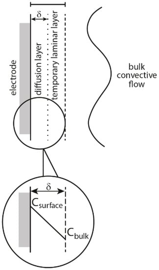
Figure 1.
Schematic representation of the diffusion and boundary layers at the electrode-solution interface as applied in the diffusion layer model. Reprinted from [20] by permission of John Wiley & Sons, Inc.
Increased hardness of the deposit, enlarged film thickness, improved deposition rates and efficiencies, greater adhesion of the deposits to electrode, and brightness enhancement are the most often mentioned benefits of electrodeposition of metals assisted with ultrasound [21,22,23]. The brightness of deposits depends on the current density and it decreases when current density increases above a critical value. The use of ultrasound increases the critical current density and helps to obtain electrodeposits with increased brightness. The ultrasound effects that influence the brightness come from shock waves followed by cavitation erosion. As a result, films built of fine grain size and higher grain-packing density are produced.
The synergism between sound and light in sonophotochemical processes is most often correlated with the enhanced mass transfer induced by ultrasound that can affect the photochemical reaction rates [6]. However, the interaction between sono- and photochemical irradiation strictly depends on the type of ultrasound effect produced in the liquid, which is shown in detail in Figure 2. It can be seen that this enhanced mass transfer can in consequence improve light absorption and modify the reaction pathway. The energy transfer to molecules occurs only when cavitation is produced. The transfer of photoexcited states in a pure photochemical system is not homogeneous (see Figure 3a), because it depends on how light propagates through an absorbing medium and normally its intensity decreases with a distance [24]. It is also known, that the reaction rate in photochemical process depends on the concentration of the excited states. Figure 3b predicts how the distribution of a photoexcited stated could change when sonication is added to the system. An intense mixing provoked by cavitation and shock waves should distribute the excited states in the whole reaction volume causing the reaction rates to be more or less the same at each point of the solution. However, not only cavitation is the important factor, but also the relative formation rates, lifetimes, and further decomposition of excited species. Additionally, it was suggested that long-lived excited states could be quenched by cavitation. Another aspect of “sonophoto” synergy can be found in some works where it is said that the combined effects of ultrasound and light could potentially generate a new chemistry of photoexcited solutes under the extreme conditions inside cavitation microreactors [6]. The Colmenares group performed an experiment comparing the deposition of iron on TiO2 semiconductor, in order to obtain iron oxide, using ultrasound, light, and ultrasound coupled with light (results not published). They compared the morphology and chemical structure of these three samples to find out if a new chemistry occurred. They discovered that nanostructured hematite was the main form obtained in the sonophotodeposition as well as in the photodeposition process. In contrast, different iron oxide forms were registered after sonodeposition. This could be interpreted in that the same mechanism, mainly photocatalytically-induced electrons is responsible for the reduction of the iron precursor after compilation of “sono” with “photo”. On the other hand, a clear physical effect of ultrasound was seen in a better dispersion of Fe2O3, which was localized not only on the surface, but also in the bulk of the material. An important issue in this experiment is the reaction solution consisting of 30% of water and 70% of acetonitrile. In such environment the reductive power of sonication was probably reduced, because only a low amount of H• radicals with high reductive power could be formed. As a result, a mechanical role of sonication and a chemical role of light were found in the sonophotodeposition process in this particular case.
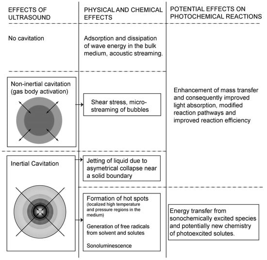
Figure 2.
Interaction of ultrasound effect with photochemical reactions. Reprinted from [6] with permission of Springer.

Figure 3.
Distribution of excited states in the photochemical process (a) and after addition of sonication (b). (Dots represent the density of activated species). Adapted from [24] with permission from Elsevier.
3. Materials Obtained by the Sonoelectrodeposition and Sonophotodeposition Processes
In this part we discuss the examples of the materials prepared by using sonoelectro- and sonophotodeposition methods, see also Table 1. The sonoelectrodeposition has already been used for preparation of vast number of materials. Herein, we describe several examples showing the diversity of the materials that can be obtained by using this method. Sonoelectrodeposition of lead oxide on glassy carbon and platinum electrodes was studied by Garcia et al. [16] (Table 1, Entry 1). In this experiment a commercial ultrasonic bath (30 kHz, 100 W) together with a platinum electrode and a glassy carbon rod as working electrodes were used. The authors observed that the behavior of these electrodes under action of ultrasound was different. The response of the platinum electrode was unchanged in comparison with silent conditions. In contrast, activation of the glassy carbon electrode during electrodeposition of lead dioxide was observed when the ultrasound was applied. Interestingly, no changes were observed in the surface topography of the electrode. Therefore the activation of the electrode was directly correlated with the formation of some surface functional groups in the reaction of OH• radicals, formed in the aqueous sonolysis, with the carbon surface. These groups play the role of intermediates in the mechanism of lead oxide deposition and are consumed as the reaction progresses. The influence of ultrasound power and frequency on sonoelectrodeposition of PbO2 on a glassy carbon electrode was studied in the subsequent works of Garcia’s group [17,18] (Table 1, Entry 2). The sonoelectrochemical reactor consisting of a jacketed Sonoreactor (20 kHz, 100 W max. power) was used in these studies. The authors found that the increase of power as well as frequency of ultrasound had an influence on the kinetics of the electrodeposition process, increasing the nucleation constant and decreasing the induction time. This was correlated with the enhanced generation of OH• radicals, which can be adsorbed on the electrode surface and therefore the number of nucleation centers should be increased. A formed nucleus favors the lead oxide deposition. However, the potential of the electrode also influences the electrodeposition, therefore these experiments were performed under conditions where the electrodeposition process was not favored. Glassy carbon was also used as a substrate in the next experiment with deposition of lead oxide film performed by Saez et al. [25] (Table 1, Entry 3). They used two experimental setups, one consisted of a sonoreactor (20 kHz) and plates of graphite as substrate electrodes and in the other one an ultrasound bath (40 kHz, 100 W) with larger plates of graphite or titanium as electrodes were applied (see Figure 4). The obtained results were compared with the mechanical agitation procedure. The authors discovered that only the ultrasound field enhanced the electrodeposition of lead oxide providing a finer grain, more homogeneous, stress-free and nodule-free film deposit on both substrates. Acoustic streaming and microjets were mainly responsible for the good adherence of the film on the coarse and rough surface of the electrode substrate. The only drawback was a random presence of pores. To avoid them, the specific pretreatment of the electrode surface was suggested as well as study of the application of high-frequency ultrasound fields.

Table 1.
Examples of different materials prepared by sonoelectrodeposition and sonophotodeposition methods.
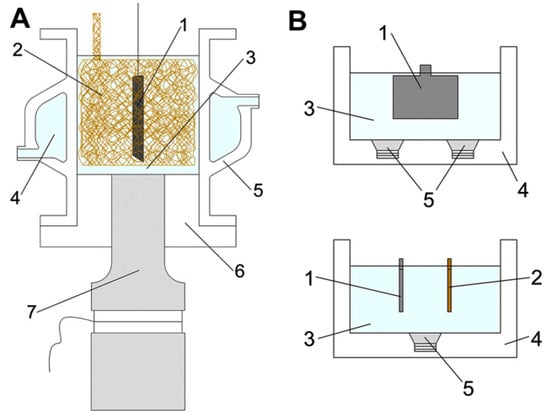
Figure 4.
(A) 20 kHz sonoreactor adapted as a sonoelectrochemical device: (1) lead dioxide electrode, (2) copper counter-electrode (foam geometry), (3) working solution, (4) cooling jacket, (5) glass cell, (6) Teflon holder, (7) ultrasonic transducer. (B) 40 kHz ultrasound bath: (1) lead dioxide electrode, (2) copper counter-electrode, (3) working solution, (4) ultrasonic bath, (5) ultrasonic transducers. Reprinted from [25] with permission from Elsevier.
The first trial of sonoelectrodeposition of platinum on a glassy carbon electrode was reported by Pollet et al. [26] (Table 1, Entry 4). For this, a special jacketed cooling electrochemical cell with a 20 kHz ultrasonic probe was designed. It was confirmed by the authors that for the formation of Pt deposits a substantial overpotential is required and that the whole process is irreversible. In the process driven under sonication the positive shift in potentials provoked a decrease in concentration and nucleation overpotentials thus facilitating the electrodeposition of platinum. They also observed a significant difference between morphology of the Pt deposits obtained under silent conditions in comparison with forced convection conditions, like rotation and sonication. Individual Pt nanoparticles deposits were produced with no agitation whereas agglomerates of larger Pt nanoparticles were formed under sonication and rotation. In this work, the use of continuous ultrasound had a detrimental effect on the electrocatalytic performance of the fuel cell in comparison with the pulsed ultrasound used in galvanostatic deposition reported earlier by the same author [27]. Later on, more sophisticated platinum structures were obtained by using sonoelectrodeposition. Heli et al. [28] reported the synthesis of platinum hierarchical nanoflowers, whereas fractal nanoplatinum structures were synthesized by Taguchi et al. [29]. More information on these materials is collected in Table 1, Entries 5 and 6, respectively.
Biomedical materials were synthesized using sonoelectrochemical deposition by Han et al. [30] (Table 1, Entry 7). Calcium phosphate (CaP) coatings were deposited on carbon fibers creating bioceramic composites which could be used to reconstruct bone defects. For this purpose, highly irregular objects often need to be coated and the electrodeposition method makes this task easier in comparison with other available methods. The synthesis setup consisted of an ultrasonic bath (40 kHz, 2.16 W/cm2), carbon fabric as the working electrode and the whole procedure was performed under a constant current density (20 mA/cm2). The authors observed that the action of ultrasound significantly influences morphology as well as the chemical composition of the CaP coatings. Figure 5 compares the morphology of the coatings electrodeposited under silent mode vs. sonoelectrodeposited. It is clearly seen that application of silent mode resulted in the formation of a porous layer with plate-like crystals (~1 µm) or small spheres. In contrast, very uniform coatings, with small needle-like crystals (<0.1 µm) and a good adhesive strength were obtained under sonication mode. Regarding the chemical structure it was discovered that application of ultrasound promoted the formation of PO43− instead of HPO42−. Concluding, the CaP coatings obtained with the use of ultrasound were more accepted by the osteoblast cells.
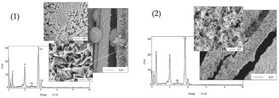
Figure 5.
Morphologies and composition of CaP obtained by: (1) electrodeposition in the absence of sonication vs. (2) sonoelectrodeposition. Reprinted from [30] with permission from Elsevier.
The influence of different current densities (5, 8, 13, 20, and 34 mA/cm2) on morphologies and structures of CaP coatings on carbon surfaces prepared by sonoelectrodeposition was studied by Han et al. in the next work [31] (Table 1, Entry 8). It was observed that morphology of the CaP deposits changed with increasing current density (see Figure 6). The plate-like crystals were formed at the lowest current density 5 mA/cm2, a mixture of spherical and needle-like structures appeared at 8 mA/cm2. The further increase of the value of current density resulted in the formation of needle-like morphology with more uniform structures and smaller crystal sizes as the current density grew. It was concluded that at the lower current density an insufficient concentration of OH− ions was the cause of formation of octacalcium phosphate. On the other hand, the higher current densities and the needle-like morphology confirmed the formation of the apatite form of calcium phosphate.
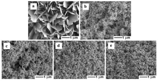
Figure 6.
Scanning electron microscopy (SEM) micrographs of the samples prepared by sonoelectrodeposition under different current densities. (a) 5 mA/cm2; (b) 8 mA/cm2; (c) 13 mA/cm2; (d) 20 mA/cm2; and (e) 34 mA/cm2. Reprinted from [31] with permission of Springer.
Another work in this field was dedicated to the formation of hydroxyapatite/porous carbon composite scaffolds and reported by Liu et al. [32] (Table 1, Entry 9). The obtained material was homogeneously coated with the needle- or sheet-shaped crystals of hydroxyapatite such as on the external and internal surface of the scaffold. This uniform coating ensured an adequate microenvironment and promoted the adhesion and proliferation of osteoblast cells, no matter of the location on the porous carbon scaffold. The biomedical application of CaP coatings makes them an interesting topic for many research groups and therefore, there are many works available in the literature. Also Zhao et al. obtained a nano/micro-sized CaP coating prepared on carbon/carbon composites [33] (Table 1, Entry 10). The obtained coating consisted of hydroxyapatite and brushite. The authors observed that at different deposition voltages the morphology of the crystals changed. In the most homogenous coating (voltage of deposition 2.4 V) the nano-sized and needle-like crystals of hydroxyapatite were embedded in a micro-sized and plate-like structure of brushite. This homogeneous structure resulted in an enhanced adhesive and cohesive strength of the coating.
An intriguing work was performed by Wang et al., who filled in TiO2 nanotubes with CdS nanoparticles through a single-step sonoelectrodeposition method [34] (Table 1, Entry 11). In this experiment TiO2NTs as a working electrode, and an ultrasonic bath (40 kHz, 2.4 kW/m2) under constant current density (5 mA/cm2) were used. Deposition of CdS nanoparticles inside the TiO2 nanotubes was facilitated by the action of ultrasound, which is shown in Figure 7. First of all, ultrasound promoted dissolution of elemental sulfur. Next, it enhanced expelling of the air from the nanotubes, which was a process that enabled the ions to enter inside the tube. Finally, ultrasound helped to obtain smaller and uniformly sized CdS nanoparticles. A real effect of this process is presented below in the transmission electron microscopy (TEM) image (Figure 7, on the right). An ordered tubular structure of TiO2 with CdS nanoparticles deposited into the channels is clearly seen. This result also confirms that ultrasound did not damage the ordered structure of the TiO2NTs during sonoelectrodeposition of CdS nanoparticles. Such obtained CdS-TiO2NTs electrodes gave a stronger photocurrent and an extended photoresponse under visible light (up to 480 nm) in comparison with the CdS-TiO2NTs electrodes prepared using electrodeposition without sonication.
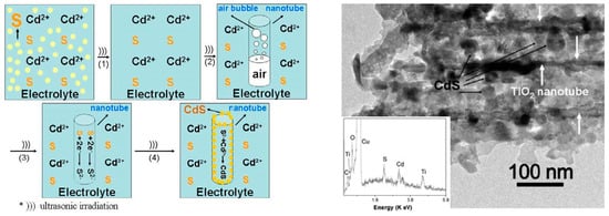
Figure 7.
On the left: a schematic diagram of the possible sonoelectrochemical deposition interaction. On the right: a transmission electron microscopy (TEM) image of CdS-TiO2NTs after CdS sonoelectrochemical deposition with the inset energy dispersive X-ray (EDX) spectrum. Reprinted from [34]. © IOP Publishing. Reproduced with permission. All rights reserved.
The impact of deposition temperature on the residual stress of Cu films sonoelectrodeposited on the graphite substrate was investigated by Mallik et al. [35] (Table 1, Entry 12). The experiments were carried out on a graphite electrode using an ultrasonic probe (20 kHz, 20% output) at different temperatures: 25, 20, 15, 10, and 5 °C. It was observed that the type of residual stress in the Cu films was only compressive, which means that films “want” to expand, at each applied deposition temperature. The maximum value of compressive residual stress was registered at the lowest deposition temperature, 5 °C. The mechanical properties of the films are strongly related with the residual stress. Therefore, the maximum values of hardness, elasticity, and surface adhesion at the grain surface were also obtained at 5 °C. This could be correlated with the effects of residual compressive stresses on suppressing crack propagation. Interestingly, an opposite tendency was observed for adhesion at grain boundaries, which decreased together with the deposition temperature. Such behavior was ascribed to changes in energy of the grains on the surface and at the boundaries as well as to some interfacial tension occurring during the atomic force microscopy (AFM) measurement. Ultrasound was reported to have a significant enhanced effect on the magnitude of the compressive stress by increasing the adatom mobility and attachment of the islands with a substrate. Also the impact of low deposition temperature on the morphology of the copper deposition was studied by Mallik et al. [36] (Table 1, Entry 13). Temperatures selected for this experiment were as following: 25, 19.5, −1 and −3 °C, and an ultrasonic bath (30 kHz, 60 W) was the source of sonication. Different results between sonicated and silent conditions as well as between ambient and low temperatures are clearly seen in Figure 8. Inhomogeneous morphology consisted of near granular as well as highly distorted areas with some perforated grains obtained at 25 °C under sonication (Figure 8a (i)). This distortion was explained by the ablating effect of microstream jetting. At lower temperature 19.5 °C and under sonication (Figure 8b (i)) bimodal faceted Cu structures with bigger and smaller grains were deposited. Enhanced mass transport by ultrasound, improved bulk deposition, simultaneous nucleation, and grain growth were some of the factors responsible for this result according to the authors. The corresponding samples at silent conditions (Figure 8a (ii) and Figure 8b (ii)) presented dendritic structures. Totally different morphology of Cu films was obtained at −1 °C temperature with sonication. In Figure 8c (i) a uniform copper covered surface with well agglomerated spheroids is seen. The low temperature, favoring the formation of small nuclei, improved the rate of mass transfer, creating enhanced nucleation, as well as degassing of the electrode surface by ultrasound, giving adherent and bright deposits, which were favorable for the obtained morphology. Similarly, the deposit formed at −3 °C presented a uniform and fully coalesced fine grained Cu coating (Figure 8d (i)). Conversely, the deposits obtained at silent mode (Figure 8c (ii) and Figure 8d (ii)) showed branched, not dense structures.
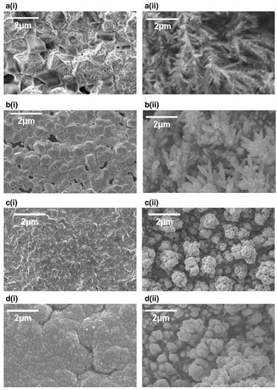
Figure 8.
SEM images of copper deposits with (i) and without (ii) sonication at (a) 25, (b) 19.5, (c) −1 and (d) −3 °C. Reprinted from [36] with permission from Elsevier.
The effect of ultrasound amplitude on the formation of poly(pyrrole) PPy/Prussian blue (PB) and poly(pyrrole) Ppy/dodecylbenzenosulphonate (DBS) nanocomposites was investigated by Hostert et al. [37,38] (Table 1, Entries 14 and 15). The following amplitudes of ultrasonic horn (20 kHz, 130 W) were checked at: 20%, 40%, and 60%. It was found that by changing the amplitude of ultrasound the morphology and distribution of nanoparticles on the electrode can be tuned. The influence of different US amplitude on the ITO electrode modified by PPy/Fe(CN)64− and PPy/PBnano is presented in Figure 9 [37]. A similar globular morphology is clearly seen under silent as well as at each US amplitude for the control electrode non-modified with Prussian blue. In contrast, on the surface of PPy/PBnano electrode the globules with inorganic structures are only seen at 20% amplitude conditions. At the higher amplitudes (40% and 60%) rather smooth surfaces with very small aggregates are seen, which can originate both organically and inorganically. This enhanced surface morphology was explained by better inclusion of small PBnano nanoparticles within PPy film under increased sonication. The PPy/PBnano electrode presented enhanced electrochemical features such as good stability over continuous cycling and sensitivity towards reduction of H2O2. Similarly, a smoother film deposit with a distinct voltammetric behavior was obtained in the case of Ppy/DBS electrodes under sonochemical conditions [38]. It was also observed that the use of ultrasound facilitated the charge-transfer process at the Ppy/electrolyte interface and resulted in different charge distribution, explained by different amounts of intercalated DBS anions.
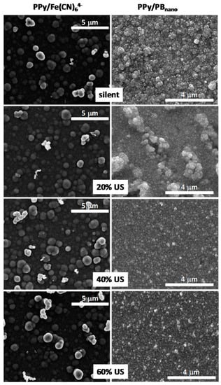
Figure 9.
Representative FEG-SEM images taken from ITO electrodes modified by PPy/Fe(CN)64− and PPy/PBnano employing different US amplitude. All electrodes were modified by the same PPy deposition charge 160 mC/cm2. Reprinted from [37] with permission from Elsevier.
A series of work regarding formation of bimetallic nanoparticles by using sonoelectrodeposition method was reported by Luong et al. [39,40,41]. Co-Pt nanoparticles were sonoelectrodeposited and then thermally treated under CO to become encapsulated within carbon cages [39] (Table 1, Entry 16). For this aim an ultrasonic horn was used in a dual role: as a cathode and ultrasound emitter working in a pulse mode. The authors observed the formation of a heterogeneous CoPt film with separate population of Pt-rich and Co-rich particles after the sonoelectrodeposition process. This was explained by different deposition rates of these elements, because of the differences in their standard electrode potentials. Annealing in the CO resulted in the creation of many core-shell structures with metallic cores and carbon-onion shells (see Figure 10). Also a hard magnetic Co-Pt phase was registered. A similar reaction setup was used for the preparation of FePt nanoparticles [41] (Table 1, Entry 17), although the annealing step was performed under H2. Similarly to the previous example the sonoelectrodeposition of Fe and Pt led to formation of small domains of pure Fe and Pt. Again, a large difference between the standard electrode potential of Fe2+ and Pt4+ was given as a reason for the lack of alloy formation. After annealing, when diffusion processes occur, the ordered L10 face-centered tetragonal (fct) FePt phase was registered. Also, the saturation magnetization and the coercivity of the nanoparticles were improved after the annealing process. Similar results were obtained in the recent work of this group reporting the synthesis of FePd nanoparticles [40] (Table 1, Entry 18). The annealing process under (Ar + 5% H2) atmosphere also resulted in the formation of an ordered L10 fct FePd structure with hard magnetic properties. In the electrodeposition of metallic nanoparticles ultrasound helped to remove the nanoparticles which were growing on the cathode surface.
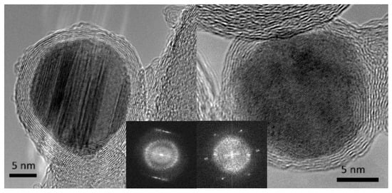
Figure 10.
HRTEM images of typical encapsulated nanoparticles, with (inset) the central portions of their respective Fourier transforms to indicate the good crystallinity of both core (sharp spots/streaks in the Fourier transform) and the well-defined ring that arises from the carbon shell. Reprinted from [39] © IOP Publishing. Reproduced with permission. All rights reserved.
It is worth mentioning other researchers and their contribution to sonoelectrodeposition studies, however we will not discuss them in detail here. Chang et al. reported preparation of Ni-Co/Al2O3 composite coating with improved properties due to the use of ultrasound [42] (Table 1, Entry 19). Better properties of Zn-Ni-Al2O3 coating electrodeposited in ultrasound assistance, especially corrosion resistance and hardness, were also found in the works done by Zheng et al. (Table 1, Entries 20 and 21) [43,44]. Noble metals Ag and Au structures were also synthesized by using sonoelectrodeposition. Cheng et al. reported the formation of differentially shaped Ag nanoparticles [45] (Table 1, Entry 22), Tuan et al. obtained Ag NPs loaded on active carbon [46] (Table 1, Entry 23) whereas the synthesis of gold nanorods was proposed by Rahi et al. [47] (Table 1, Entry 24). An interesting combination of sonoelectrodeposition with galvanic replacement was proposed by Rousse et al. [48] (Table 1, Entry 25) for the synthesis of copper-silver bimetallic nanopowders. Sonoelectrodeposition was used for the preparation of the inner copper core whereas the galvanic reaction allowed the replacement of surface copper atoms by silver atoms forming an outer shell. The synthesis of iron-chromium alloy nanoparticles employing pulsed sonoelectrodeposition was performed by Zin et al. [49] (Table 1, Entry 26). The effects of different synthesis parameters, such as bath temperature, pH, and electrolyte composition, on process efficiency and nanoparticles features were studied. The effect of sonication on electroplating of iridium was investigated by Ohsaka et al. [50] (Table 1, Entry 27). A very interesting work comparing direct current electrodeposition and pulse electrodeposition with sono-assisted direct current electrodeposition and sono-assisted pulse electrodeposition in the synthesis of the NiZnS electrode was done by Seetharaman et al. [51] (Table 1, Entry 28). Pulse electrodeposition enabled higher cathodic current density to be applied at the electrode interface and to control surface properties of the composite coatings. Sonication added to this method increased surface smoothness and decreased the residual stresses of the electrode. The best performance in the oxygen evolution studies showed an electrode prepared by the sono-assisted pulse electrodeposition method. A simplified scheme reflecting the key of sonoelectrodeposition is presented in Figure 11.

Figure 11.
A schematic representation of the synthesis of the materials by means of the sonoelectrodeposition method.
On the other hand, not many examples concerning materials obtained by the sonophotodeposition method could be found in the literature. For example, this method was implemented and studied by Colmenares group. For the last two years they have reported preparation of several titania-based photocatalytic systems. We will briefly overview these works. The first trial of sonophotodeposition of metal nanoparticles on the surface of a semiconductor concerned palladium on the commercial TiO2 P90 photocatalyst [52] (Table 1, Entry 29). The reaction setup consisted of an ultrasonic bath and a 6W Hg lamp (λmax = 254 nm), which is presented in Figure 12a. In all photocatalyst (0.5 wt%, 1 wt%, and 2 wt% Pd) palladium was totally reduced to the metallic form although the air calcination step was the last in the synthesis procedure. These results of sonophotodeposition were compared with the traditional photodeposition where the palladium oxide was the only detected form on the surface. Therefore, the crucial role in formation of Pd° was ascribed in the sonophotodeposition method to sonochemically formed radicals. The authors claimed that these radicals could additionally remove the oxygen atoms from the organometallic structure of the palladium precursor. As a result, the residual carbon combined with the oxygen from the air flow and palladium was not oxidized. The same semiconductor, TiO2 P90, and the same reaction setup were then used in the synthesis of bimetallic samples Pd-Au/TiO2 and Pd-Cu/TiO2 reported in the next two articles [53,54]. The simultaneous sonophotodeposition of palladium and gold resulted in the complete reduction of gold whereas palladium was partially reduced to the metallic form as well as the PdO form being also detected [53] (Table 1, Entry 30). The authors observed the formation of random alloys between the Pd-Au nanoparticles as well as a strong metal-support interaction effect (SMSI) between these nanoparticles and TiO2. According to the authors the formation of SMSI effect could be a result of the shock waves and interparticle collisions produced by cavitation. It is important to mention that this effect was observed only in the case of one photocatalyst with a specific composition of metals (1 wt% Pd50-Au50/TiO2 P90), which means that the amount of the introduced metals must be optimized. The SMSI effect had a strong influence on the photocatalytic results, in terms of gas phase conversion of methanol and selectivity to methyl formate. In contrast, the monometallic 1 wt% Pd/TiO2 P90 photocatalyst was not active in the selective photoreaction towards methyl formate. Similarly, in the sonophotodeposition of palladium and copper, metallic copper and palladium as well as palladium oxide were obtained [54] (Table 1, Entry 31). The partial reduction of palladium was explained by the presence of copper and the retarding effect that it could have on the total reduction process of Pd. Also the SMSI effect was observed for 1 wt% Pd-Cu(1-1)/TiO2 P90 photocatalyst, which at the same time was the best performing material in the gas phase oxidation of methanol. Concluding, the addition of a second metal, gold or copper, to palladium significantly changed the reaction route. Generally worse results in this reaction were obtained for the photocatalysts prepared by the photodeposition method. In the next work iron and noble metal (Pt-Fe and Pd-Fe pairs) were sonophotodeposited on the self-prepared TiO2/zeolite Y semiconducting material [55] (Table 1, Entry 32). Different forms of deposited metals were determined by their reduction potentials. Platinum has the largest positive reduction potential among these metals. Therefore, Pt2+ was easily reduced to the metallic form in comparison with Fe3+, which is a stronger reducer and undergoes an easy oxidation during the air calcination step. As a result, mainly Pt° and Fe3+ forms were obtained in the Pt-Fe/TiO2/zeolite Y photocatalyst. In the case of the Pd-Fe/TiO2/zeolite Y photocatalyst Pd2+ form dominated over the Pd° and also the Fe3+ form of iron was detected. Palladium has smaller positive reduction potential than platinum therefore it could be more easily oxidized during the air calcination. A very good dispersion of platinum nanoparticles with the average size between 2 and 3 nm was obtained using the sonophotodeposition method. These good morphological properties as well as the formation of Schottky barrier between Pt° and TiO2 resulted in better activity of this photocatalyst in liquid phase phenol degradation. The authors also observed that the particles of deposited metals are in close vicinity to TiO2 particles, however formation of any specific structure (e.g., alloys, core-shell) was not confirmed by other techniques. A different reaction setup, consisted of an ultrasonic horn and a sun-imitating Xenon lamp (see Figure 12b) was checked in the sonophotodeposition of iron on the self-prepared TiO2/zeolite Y material [56] (Table 1, Entry 33). Iron was sonophotodeposited as the Fe3+ form and was mostly located in the bulk of the photocatalyst. In contrast, Fe3+ iron surface enrichment was observed when an ultrasound-assisted wet impregnation method was applied for the synthesis of similar Fe/TiO2/zeolite Y system. The authors were looking for the explanation of this behavior in different ultrasound-operating zones, from inside in the reactor sonication horn applied in the sonophotodeposition method, and from outside of the reactor in the ultrasonic bath used in the ultrasound-assisted wet impregnation method. The amount of iron on the surface of the photocatalyst was directly correlated with the results of selective photo-oxidation of benzyl alcohol into benzaldehyde, which were better for the photocatalyst prepared by the sonophotodeposition method. A simplified scheme reflecting the key of sonophotodeposition is presented in Figure 13.
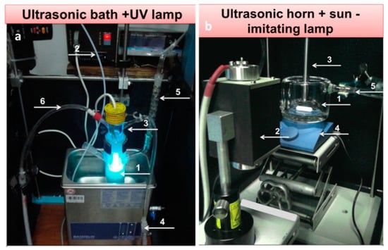
Figure 12.
Different reaction setups for the sonophotodeposition synthesis: (a) US bath-UV lamp setup: (1) batch photoreactor, (2) argon line, (3) 6 W UV lamp, (4) ultrasonic bath, (5) reflux condenser (6) lamp cooling system; (b) US horn-Xe lamp setup: (1) photoreactor, (2) 150 W Xe lamp, (3) ultrasonic horn, (4) magnetic stirrer and (5) cooling system.

Figure 13.
A schematic representation of the synthesis of the materials by means of the sonophotodeposition method.
4. Final Remarks
A comparison between the mechanism of sonoelectro- and sonophotodeposition is schematically presented in Figure 14. The chemistry of these processes is totally different (electrochemical reactions vs. photoexcitation), however their synergism with ultrasound is mainly based on the cavitation process and within that the enhanced mass transfer. In the case of sonoelectrodeposition the enhanced mass transfer is usually seen as the increase of electrochemical current or as the increased current pulses, depending on the type of physical effect. Such activation of electrodes results mainly in better mechanical properties of the deposits and electrocatalytic performance. On the other hand, in sonophotodeposition it influences mainly the transfer of photoexcited states. This is mostly reflected in the enhanced photochemical reaction rates, but can also end in a modified reaction pathway.
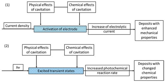
Figure 14.
Schematic representation summarizing both (1) sonoelectrodeposition and (2) sonophotodeposition processes.
The variety of the materials obtained by sonolectrodeposition and sonophotodeposition methods is collected in Table 1. The cited examples prove that the combination of sonication with electrodeposition has already brought a new strategy for the synthesis of nanomaterials. On the other hand, not many examples of combination between sonication and photodeposition leave a free space for future research in this area. As has been mentioned in the introductory part, this short review covers a very specific topic and discusses the synergy of “sonophoto and sonoelectro” only in the field of the synthesis of materials. However, there are different applications of such synergy described in the literature. For instance, the combination of ultrasound and light in homogeneous and heterogeneous liquid systems, the influence of ultrasound on photocatalytic decomposition reactions or excitation of solutes by sonoluminescence can be found in the works of Rosenthal et al. [6], Toma et al. [24] or Gogate [57]. A wide range of application of sonoelectrochemistry was reviewed by Garcia et al. [7] and references therein. For instance, sonoelectroanalysis [20,58,59], sonoelectrochemical environmental remediation [57,60], or sonoelectrochemistry in the synthesis of nanomaterials [61] are currently very active research areas.
Acknowledgments
J.C. Colmenares is very grateful for the support from the National Science Centre in Poland within Sonata Bis Project No. 2015/18/E/ST5/00306. Agnieszka Magdziarz wants to thank the National Science Centre (NCN) in Poland for the support within the research project DEC-2013/11/N/ST5/01923.
Conflicts of Interest
The authors declare no conflict of interest. The founding sponsors had no role in the design of the study; in the collection, analyses, or interpretation of data; in the writing of the manuscript, and in the decision to publish the results.
References
- Klima, J. Application of ultrasound in electrochemistry. An overview of mechanisms and design of experimental arrangement. Ultrasonics 2011, 51, 202–209. [Google Scholar] [CrossRef]
- Compton, R.G.; Eklund, J.C.; Marken, F. Sonoelectrochemical processes: A review. Electroanalysis 1997, 9, 509–522. [Google Scholar] [CrossRef]
- Compton, R.G.; Dryfe, R.A.W. Photoelectrochemical studies. Prog. React. Kinet. 1995, 20, 245–307. [Google Scholar]
- Gonzalez-Garcia, J. Sonoelectrochemical synthesis of materials. In Theoretical and Experimental Sonochemistry Involving Inorganic Systems; Pankaj, Ashokkumar, M., Eds.; Springer: Dordrecht, The Netherlands, 2011; pp. 107–129. [Google Scholar]
- Gedanken, A. Sonochemistry and its application to nanochemistry. Current Science 2003, 85, 1720–1722. [Google Scholar]
- Rosenthal, I.; Sostaric, J.Z.; Riesz, P. Enlightened sonochemistry. Res. Chem. Intermed. 2004, 30, 685–701. [Google Scholar] [CrossRef]
- Gonzalez-Garcia, J.; Esclapez, M.D.; Bonete, P.; Hernandez, Y.V.; Garreton, L.G.; Saez, V. Current topics on sonoelectrochemistry. Ultrasonics 2010, 50, 318–322. [Google Scholar] [CrossRef] [PubMed]
- Eklund, J.C.; Marken, F.; Waller, D.N.; Compton, R.G. Voltammetry in the presence of ultrasound: A novel sono-electrode geometry. Electrochim. Acta 1996, 41, 1541–1547. [Google Scholar] [CrossRef]
- Hagan, C.R.S.; Coury, L.A. Comparison of hydrodynamic voltammetry implemented by sonication to a rotating-disk electrode. Anal. Chem. 1994, 66, 399–405. [Google Scholar] [CrossRef]
- Benjamin, T.B. Solitary and periodic waves of a new kind. Philos. T. Roy. Soc. A 1996, 354, 1775–1806. [Google Scholar] [CrossRef]
- Compton, R.G.; Eklund, J.C.; Marken, F.; Rebbitt, T.O.; Akkermans, R.P.; Waller, D.N. Dual activation: Coupling ultrasound to electrochemistry—An overview. Electrochim. Acta 1997, 42, 2919–2927. [Google Scholar] [CrossRef]
- Macounova, K.; Klima, J.; Bernard, C.; Degrand, C. Ultrasound-assisted anodic oxidation of diuron. J. Electroanal. Chem. 1998, 457, 141–147. [Google Scholar] [CrossRef]
- Madigan, N.A.; Hagan, C.R.S.; Coury, L.A. Preparation of microarray electrodes by sonochemical ablation of polymer-films. J. Electrochem. Soc. 1994, 141, L23–L24. [Google Scholar] [CrossRef]
- Klima, J.; Bernard, C. Sonoassisted electrooxidative polymerisation of salicylic acid: Role of acoustic streaming and microjetting. J. Electroanal. Chem. 1999, 462, 181–186. [Google Scholar] [CrossRef]
- Zhang, H.H.; Coury, L.A. Effects of high-intensity ultrasound on glassy-carbon electrodes. Anal. Chem. 1993, 65, 1552–1558. [Google Scholar] [CrossRef]
- Gonzalez-Garcia, J.; Iniesta, J.; Aldaz, A.; Montiel, V. Effects of ultrasound on the electrodeposition of lead dioxide on glassy carbon electrodes. New J. Chem. 1998, 22, 343–347. [Google Scholar] [CrossRef]
- Gonzalez-Garcia, J.; Saez, V.; Iniesta, J.S.; Montiel, V.; Aldaz, A. Electrodeposition of PbO2 on glassy electrodes: Influence of ultrasound carbon power. Electrochem. Commun. 2002, 4, 370–373. [Google Scholar] [CrossRef]
- Saez, V.; Gonzalez-Garcia, J.; Iniesta, J.D.; Frias-Ferrer, A.; Aldaz, A. Electrodeposition of PbO2 on glassy carbon electrodes: Influence of ultrasound frequency. Electrochem. Commun. 2004, 6, 757–761. [Google Scholar] [CrossRef]
- Mallik, A.; Bankoti, A.; Ray, B.C. A study on the modification of conventional electrochemical crystallization under sonication: The phenomena of secondary nucleation. Electrochem. Solid St. 2009, 12, F46–F49. [Google Scholar] [CrossRef]
- Banks, C.E.; Compton, R.G. Ultrasonically enhanced voltammetric analysis and applications: An overview. Electroanalysis 2003, 15, 329–346. [Google Scholar] [CrossRef]
- Lorimer, P.; Mason, T.J. The applications of ultrasound in electroplating. Electrochemistry 1999, 67, 924–930. [Google Scholar]
- Walker, R. Ultrasound and electroplating. Chem. Brit. 1990, 26, 251–254. [Google Scholar]
- Walker, R.; Walker, C.T. New explanation for brightness of electrodeposits produced by ultrasound. Ultrasonics 1975, 13, 79–82. [Google Scholar] [CrossRef]
- Toma, S.; Gaplovsky, A.; Luche, J.L. The effect of ultrasound on photochemical reactions. Ultrason. Sonochem. 2001, 8, 201–207. [Google Scholar] [CrossRef]
- Saez, V.; Esclapez, M.D.; Frias-Ferrer, A.J.; Bonete, P.; Tudela, I.; Diez-Garcia, M.I.; Gonzalez-Garcia, J. Lead dioxide film sonoelectrodeposition in acidic media: Preparation and performance of stable practical anodes. Ultrason. Sonochem. 2011, 18, 873–880. [Google Scholar] [CrossRef] [PubMed]
- Pollet, B.G.; Valzer, E.F.; Curnick, O.J. Platinum sonoelectrodeposition on glassy carbon and gas diffusion layer electrodes. Int. J. Hydrogen Energy 2011, 36, 6248–6258. [Google Scholar] [CrossRef]
- Pollet, B.G. A novel method for preparing pemfc electrodes by the ultrasonic and sonoelectrochemical techniques. Electrochem. Commun. 2009, 11, 1445–1448. [Google Scholar] [CrossRef]
- Heli, H.; Sattarahmady, N.; Vais, R.D.; Mehdizadeh, A.R. Enhanced electrocatalytic reduction and highly sensitive nonenzymatic detection of hydrogen peroxide using platinum hierarchical nanoflowers. Sensor. Actuat. B-Chem. 2014, 192, 310–316. [Google Scholar] [CrossRef]
- Taguchi, M.; Schwalb, N.; Rong, Y.; Vanegas, D.C.; Garland, N.; Tan, M.; Yamaguchi, H.; Claussen, J.C.; McLamore, E.S. Pulsed: Pulsed sonoelectrodeposition of fractal nanoplatinum for enhancing amperometric biosensor performance. Analyst 2016, 141, 3367–3378. [Google Scholar] [CrossRef] [PubMed]
- Han, H.M.; Mikhalovsky, S.V.; Phillips, G.J.; Lloyd, A.W. Calcium phosphate sonoelectrodeposition on carbon fabrics and its effect on osteoblast cell viability in vitro. New Carbon Mater. 2007, 22, 121–125. [Google Scholar] [CrossRef]
- Han, H.M.; Phillips, G.J.; Mikhalovsky, S.V.; FitzGerald, S.; Lloyd, A.W. Sonoelectrochemical deposition of calcium phosphates on carbon materials: Effect of current density. J. Mater. Sci.-Mater. M. 2008, 19, 1787–1791. [Google Scholar] [CrossRef] [PubMed]
- Liu, H.R.; Xia, L.L.; Dai, Y.; Zhao, M.; Zhou, Z.; Liu, H.B. Fabrication and characterization of novel hydroxyapatite/porous carbon composite scaffolds. Mater. Lett. 2012, 66, 36–38. [Google Scholar] [CrossRef]
- Zhao, X.N.; Li, H.J.; Chen, M.D.; Li, K.Z.; Lu, J.H.; Zhang, L.L.; Cao, S. Nano/micro-sized calcium phosphate coating on carbon/carbon composites by ultrasonic assisted electrochemical deposition. Surf. Interface Anal. 2012, 44, 21–28. [Google Scholar] [CrossRef]
- Wang, C.L.; Sun, L.; Yun, H.; Li, J.; Lai, Y.K.; Lin, C.J. Sonoelectrochemical synthesis of highly photoelectrochemically active TiO2 nanotubes by incorporating CdS nanoparticles. Nanotechnology 2009, 20, 295601. [Google Scholar] [CrossRef] [PubMed]
- Mallik, A.; Ray, B.C. Residual stress and nanomechanical properties of sonoelectrodeposited Cu films. Surf. Eng. 2011, 27, 551–556. [Google Scholar] [CrossRef]
- Mallik, A.; Ray, B.C. Morphological study of electrodeposited copper under the influence of ultrasound and low temperature. Thin Solid Films 2009, 517, 6612–6616. [Google Scholar] [CrossRef]
- Hostert, L.; de Alvarenga, G.; Marchesi, L.F.; Soares, A.L.; Vidotti, M. One-pot sonoelectrodeposition of poly(pyrrole)/prussian blue nanocomposites: Effects of the ultrasound amplitude in the electrode interface and electrocatalytical properties. Electrochim. Acta 2016, 213, 822–830. [Google Scholar] [CrossRef]
- Hostert, L.; de Alvarenga, G.; Vidotti, M.; Marchesi, L.F. Sonoelectrodeposition of poly(pyrrole) films: Electrochemical and morphological effects caused by the ultrasonic amplitude. J. Electroanal. Chem. 2016, 774, 31–35. [Google Scholar] [CrossRef]
- Luong, N.H.; Hai, N.H.; Phu, N.D.; MacLaren, D.A. Co-Pt nanoparticles encapsulated in carbon cages prepared by sonoelectrodeposition. Nanotechnology 2011, 22, 285603. [Google Scholar] [CrossRef] [PubMed]
- Luong, N.H.; Trung, T.T.; Loan, T.P.; Kien, L.M.; Hong, T.T.; Nam, N.H. Magnetic properties of FePd nanoparticles prepared by sonoelectrodeposition. J. Electron. Mater. 2016, 45, 4309–4313. [Google Scholar] [CrossRef]
- Nam, N.H.; Nguyen, T.T.V.; Phu, N.D.; Hong, T.T.; Hai, N.H.; Luong, N.H. Magnetic properties of FePt nanoparticles prepared by sonoelectrodeposition. J. Nanomaterials 2012. [Google Scholar] [CrossRef]
- Chang, L.M.; Guo, H.F.; An, M.Z. Electrodeposition of Ni-Co/Al2O3 composite coating by pulse reverse method under ultrasonic condition. Mater. Lett. 2008, 62, 3313–3315. [Google Scholar] [CrossRef]
- Zheng, H.Y.; An, M.Z.; Lu, J.F. Surface characterization of the Zn-Ni-Al2O3 nanocomposite coating fabricated under ultrasound condition. Appl. Surf. Sci. 2008, 254, 1644–1650. [Google Scholar] [CrossRef]
- Zheng, H.-Y.; An, M.-Z. Electrodeposition of Zn-Ni-Al2O3 nanocomposite coatings under ultrasound conditions. J. Alloys Compd. 2008, 459, 548–552. [Google Scholar] [CrossRef]
- Cheng, J.Q.; Yao, S.W. Synthesis and characterization of silver nanoparticles by sonoelectrodeposition. Rare Met. 2005, 24, 376–380. [Google Scholar]
- Tuan, T.Q.; Son, N.V.; Hoang, T.K.D.; Luong, N.H.; Thuy, B.T.; Nguyen, T.V.A.; Hoa, N.D.; Hai, N.H. Preparation and properties of silver nanoparticles loaded in activated carbon for biological and environmental applications. J. Hazard. Mater. 2011, 192, 1321–1329. [Google Scholar] [CrossRef] [PubMed]
- Rahi, A.; Sattarahmady, N.; Vais, R.D.; Heli, H. Sonoelectrodeposition of gold nanorods at a gold surface—Application for electrocatalytic reduction and determination of nitrofurazone. Sensor. Actuat. B-Chem. 2015, 210, 96–102. [Google Scholar] [CrossRef]
- Rousse, C.; Josse, J.; Mancier, V.; Levi, S.; Gangloff, S.C.; Fricoteaux, P. Synthesis of copper-silver bimetallic nanopowders for a biomedical approach; study of their antibacterial properties. RSC Adv. 2016, 6, 50933–50940. [Google Scholar] [CrossRef]
- Zin, V.; Dabala, M. Iron-chromium alloy nanoparticles produced by pulsed sonoelectrochemistry: Synthesis and characterization. Acta Mater. 2010, 58, 311–319. [Google Scholar] [CrossRef]
- Ohsaka, T.; Isaka, M.; Hirano, K.; Ohishi, T. Effect of ultrasound sonication on electroplating of iridium. Ultrason. Sonochem. 2008, 15, 283–288. [Google Scholar] [CrossRef] [PubMed]
- Seetharaman, S.; Balaji, R.; Ramya, K.; Dhathathreyan, K.S.; Velan, M. Electrochemical behaviour of nickel-based electrodes for oxygen evolution reaction in alkaline water electrolysis. Ionics 2014, 20, 713–720. [Google Scholar] [CrossRef]
- Colmenares, J.C.; Magdziarz, A.; Lomot, D.; Chernyayeva, O.; Lisovytskiy, D. A new photocatalytic tool in VOCs abatement: Effective synergetic combination of sonication and light for the synthesis of monometallic palladium-containing TiO2. Appl. Catal., B 2014, 147, 624–632. [Google Scholar] [CrossRef]
- Colmenares, J.C.; Lisowski, P.; Lomot, D.; Chernyayeva, O.; Lisovytskiy, D. Sonophotodeposition of bimetallic photocatalysts Pd-Au/TiO2: Application to selective oxidation of methanol to methyl formate. ChemSusChem 2015, 8, 1676–1685. [Google Scholar] [CrossRef] [PubMed]
- Lisowski, P.; Colmenares, J.C.; Lomot, D.; Chernyayeva, O.; Lisovytskiy, D. Preparation by sonophotodeposition method of bimetallic photocatalysts Pd-Cu/TiO2 for sustainable gaseous selective oxidation of methanol to methyl formate. J. Mol. Catal. A: Chem 2016, 411, 247–256. [Google Scholar] [CrossRef]
- Magdziarz, A.; Colmenares, J.C.; Chernyayeva, O.; Łomot, D.; Sobczak, K. Sonication and light irradiation as green energy sources simultaneously implemented in the synthesis of Pd-Fe- and Pt-Fe-doped TiO2-based photocatalysts. J. Mol. Catal. A: Chem 2016, 425, 1–9. [Google Scholar] [CrossRef]
- Magdziarz, A.; Colmenares, J.C.; Chernyayeva, O.; Kurzydlowski, K.; Grzonka, J. Iron-containing titania photocatalyst prepared by the sonophotodeposition method for the oxidation of benzyl alcohol. ChemCatChem 2016, 8, 536–539. [Google Scholar] [CrossRef]
- Gogate, P.R. Treatment of wastewater streams containing phenolic compounds using hybrid techniques based on cavitation: A review of the current status and the way forward. Ultrason. Sonochem. 2008, 15, 1–15. [Google Scholar] [CrossRef] [PubMed]
- Saterlay, A.J.; Compton, R.G. Sonoelectroanalysis: An overview. Fresenius' J. Anal. Chem. 2000, 367, 308–313. [Google Scholar] [CrossRef]
- Metters, J.P.; Kruusma, J.; Banks, C.E. Sonoelectroanalysis: An overview. In Power Ultrasound in Electrochemistry: From Versatile Laboratory Tool to Engineering Solution; Pollet, B.G., Ed.; John Wiley & Sons, Ltd.: Chichester, UK, 2012; pp. 79–99. [Google Scholar]
- Yaqub, A.; Ajab, H. Applications of sonoelectrochemistry in wastewater treatment system. Rev. Chem. Eng. 2013, 29, 123–130. [Google Scholar] [CrossRef]
- Saez, V.; Mason, T.J. Sonoelectrochemical synthesis of nanoparticles. Molecules 2009, 14, 4284–4299. [Google Scholar] [CrossRef] [PubMed]
© 2017 by the authors. Licensee MDPI, Basel, Switzerland. This article is an open access article distributed under the terms and conditions of the Creative Commons Attribution (CC BY) license ( http://creativecommons.org/licenses/by/4.0/).