
Strength Enhancement in Fused Filament Fabrication via the Isotropy Toolpath


Abstract
:Featured Application
Abstract
1. Introduction
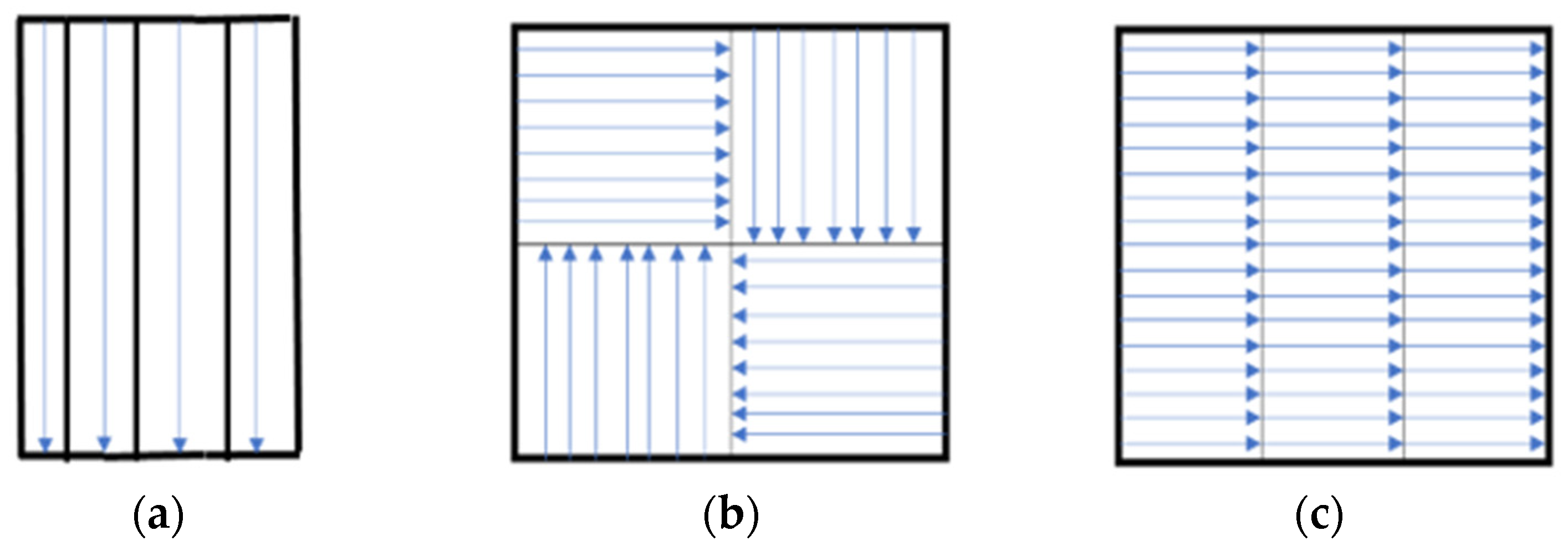
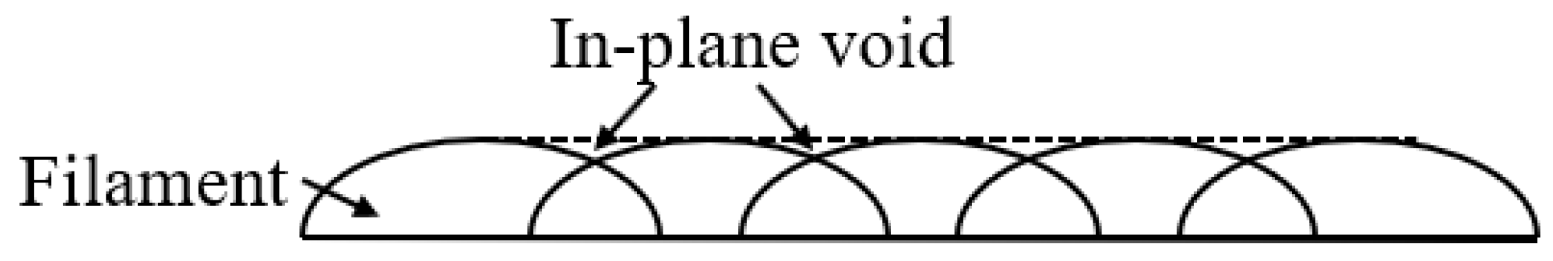
- Non-longitudinal filaments lie along one direction accumulate that induce structural anisotropy.
- A dissimilar toolpath per layer can fill up the void created by the filament (Figure 4).
2. Literature Review
2.1. Toolpath for FDM
2.2. Strategies for Enhancing Mechanical Strength
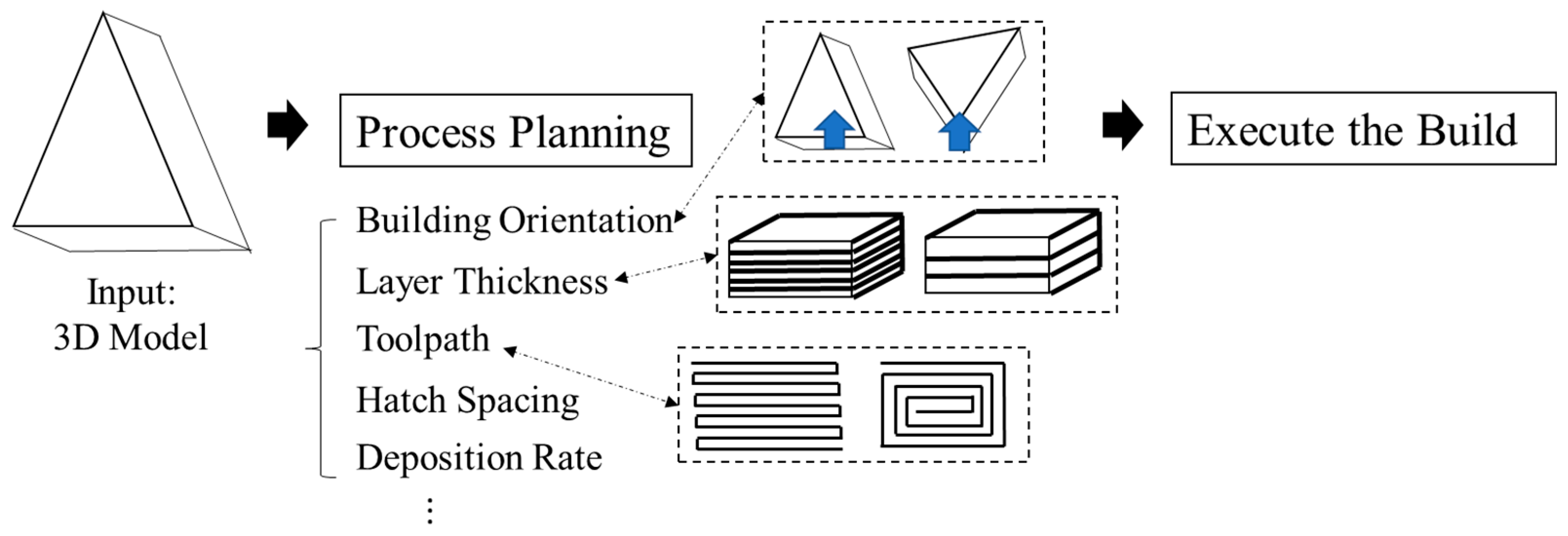
- Process parameters (building orientation, layer thickness, extrusion rate, hatch spacing…) are highly correlated. The individual adjustment on a single parameter would cause an unexpected quality change
- Lack of quantitative relationship between process parameters and process outcomes (mechanical properties), the modification of the process parameters becomes more challenging
3. Materials and Methods
3.1. Path Design
| Algorithm 1: Generation of in-plane isotropy toolpath. |
| Input: Any given 3D model, Building Orientation, Layer thickness, loading direction |
| Output: Series of layer-wised toolpath |
| 1. 3D model = |
| 2. = max_length () along with tensile test loading direction |
| 3. Initialize n particles on , allow norm () = length()/n |
| 4. |
| 5. |
| 6. max = boundary() |
| 7. Initialize n particles with randomized vector |
| 8. new() = |
| 9. Update |
| 10. End until boundary () = max |
- ,
| Algorithm 2: Generation of Process Parameters. |
| Input: Output from Algorithm 1, Printing velocity (v), layer thickness (LH) |
| Output: Extrusion Rate |
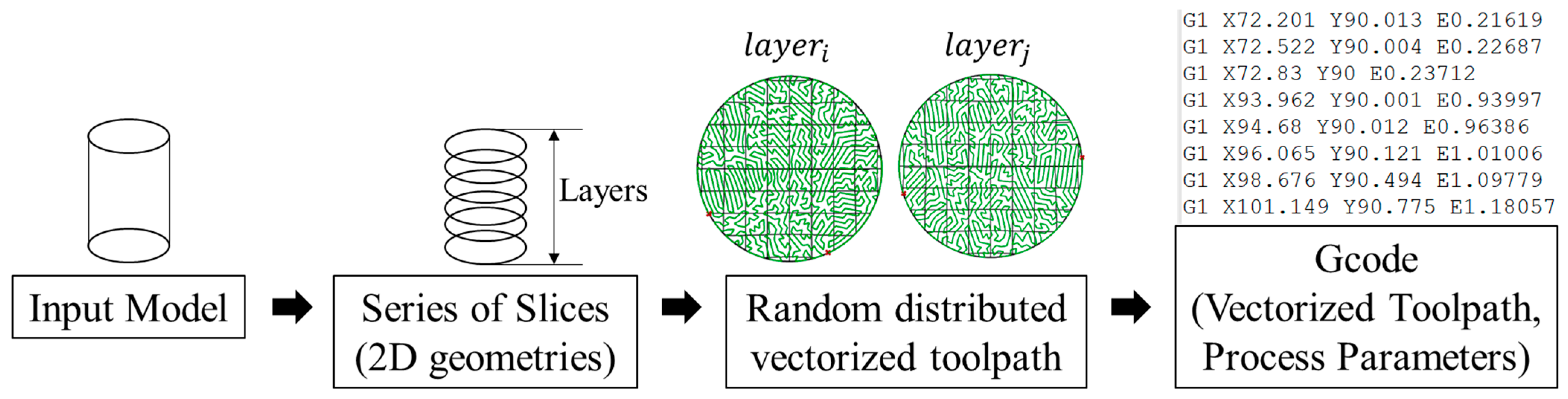
| 1. Vectorize in-plane toolpath to {[], [],…, []} |
| 2. |
| 3. |
| 4. Construct |
| 5. L = min() |
| 6. |
| 7. |
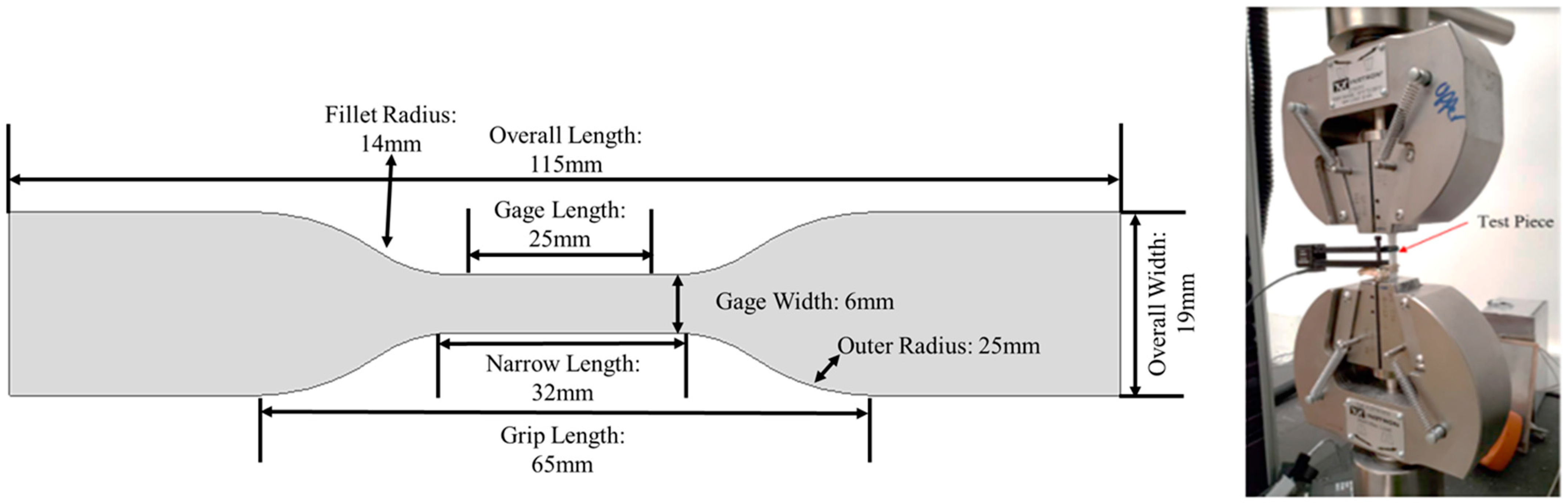
3.2. Experiments
4. Results
5. Conclusions and Discussion
Author Contributions
Funding
Institutional Review Board Statement
Informed Consent Statement
Data Availability Statement
Conflicts of Interest
References
- Jin, Y.-A.; He, Y.; Xue, G.-H.; Fu, J.-Z. A parallel-based path generation method for fused deposition modeling. Int. J. Adv. Manuf. Technol. 2015, 77, 927–937. [Google Scholar] [CrossRef]
- Volpato, N.; Zanotto, T.T. Analysis of deposition sequence in tool-path optimization for low-cost material extrusion additive manufacturing. Int. J. Adv. Manuf. Technol. 2018, 101, 1855–1863. [Google Scholar] [CrossRef]
- Castelino, K.; D’Souza, R.; Wright, P.K. Toolpath optimization for minimizing airtime during machining. J. Manuf. Syst. 2003, 22, 173–180. [Google Scholar] [CrossRef]
- Dreifus, G.; Goodrick, K.; Giles, S.; Patel, M.; Foster, R.M.; Williams, C.; Lindahl, J.; Post, B.; Roschli, A.; Love, L.; et al. Path optimization along lattices in additive manufacturing using the chinese postman problem. 3D Print. Addit. Manuf. 2017, 4, 98–104. [Google Scholar] [CrossRef]
- Lensgraf, S.; Mettu, R.R. An improved toolpath generation algorithm for fused filament fabrication. In Proceedings of the 2017 IEEE International Conference on Robotics and Automation (ICRA), Singapore, 29 May–3 June 2017; pp. 1181–1187. [Google Scholar]
- Gurrala, P.K.; Regalla, S.P. Part strength evolution with bonding between filaments in fused deposition modelling: This paper studies how coalescence of filaments contributes to the strength of final FDM part. Virtual Phys. Prototyp. 2014, 9, 141–149. [Google Scholar] [CrossRef]
- Sun, Q.; Rizvi, G.M.; Bellehumeur, C.T.; Gu, P. Effect of processing conditions on the bonding quality of FDM polymer filaments. Rapid Prototyp. J. 2008, 14, 72–80. [Google Scholar] [CrossRef]
- Pandey, P.; Reddy, N.; Dhande, S. Real time adaptive slicing for fused deposition modelling. Int. J. Mach. Tools Manuf. 2003, 43, 61–71. [Google Scholar] [CrossRef]
- Chacón, J.M.; Caminero, M.A.; García-Plaza, E.; Núñez, P.J. Additive manufacturing of PLA structures using fused deposition modelling: Effect of process parameters on mechanical properties and their optimal selection. Mater. Des. 2017, 124, 143–157. [Google Scholar] [CrossRef]
- Khosravani, M.R.; Reinicke, T. Effects of raster layup and printing speed on strength of 3D-printed structural components. Procedia Struct. Integr. 2020, 28, 720–725. [Google Scholar] [CrossRef]
- Tam, K.-M.M.; Mueller, C.T. Additive manufacturing along principal stress lines. 3D Print. Addit. Manuf. 2017, 4, 63–81. [Google Scholar] [CrossRef]
- Ultimaker.Com. Ultimaker Cura: Powerful, Easy-to-Use 3D Printing Software. 2020. Available online: https://ultimaker.com/software/ultimaker-cura (accessed on 23 June 2021).
- Goo, B.; Hong, C.-H.; Park, K. 4D printing using anisotropic thermal deformation of 3D-printed thermoplastic parts. Mater. Des. 2020, 188, 108485. [Google Scholar] [CrossRef]
- Pollard, D.; Ward, C.; Herrmann, G.; Etches, J. The manufacture of honeycomb cores using Fused Deposition Modeling. Adv. Manuf. Polym. Compos. Sci. 2017, 3, 21–31. [Google Scholar] [CrossRef] [Green Version]
- Michel, F.; Lockett, H.; Ding, J.; Martina, F.; Marinelli, G.; Williams, S. A modular path planning solution for Wire+ Arc Additive Manufacturing. Robot. Comput. Integr. Manuf. 2019, 60, 1–11. [Google Scholar] [CrossRef]
- Suksangpanya, N.; Yaraghi, N.A.; Pipes, R.B.; Kisailus, D.; Zavattieri, P. Crack twisting and toughening strategies in Bouligand architectures. Int. J. Solids Struct. 2018, 150, 83–106. [Google Scholar] [CrossRef]
- Sun, Y.; Tian, W.; Zhang, T.; Chen, P.; Li, M. Strength and toughness enhancement in 3d printing via bioinspired tool path. Mater. Des. 2020, 185, 108239. [Google Scholar] [CrossRef]
- Xiong, Y.; Park, S.-I.; Padmanathan, S.; Dharmawan, A.G.; Foong, S.; Rosen, D.W.; Soh, G.S. Process planning for adaptive contour parallel toolpath in additive manufacturing with variable bead width. Int. J. Adv. Manuf. Technol. 2019, 105, 4159–4170. [Google Scholar] [CrossRef]
- Jhabvala, J.; Boillat, E.; Antignac, T.; Glardon, R. On the effect of scanning strategies in the selective laser melting process. Virtual Phys. Prototyp. 2010, 5, 99–109. [Google Scholar] [CrossRef]
- Song, Z.; Ni, Y.; Cai, S. Fracture modes and hybrid toughening mechanisms in oscillated/twisted plywood structure. Acta Biomater. 2019, 91, 284–293. [Google Scholar] [CrossRef]
- Cuan-Urquizo, E.; Barocio, E.; Tejada-Ortigoza, V.; Pipes, R.B.; Rodriguez, C.A.; Roman-Flores, A. Character-ization of the mechanical properties of FFF structures and materials: A review on the experimental, computational and theoretical approaches. Materials 2019, 12, 895. [Google Scholar] [CrossRef] [PubMed] [Green Version]
- Xiao, X.; Joshi, S. Process planning for five-axis support free additive manufacturing. Addit. Manuf. 2020, 36, 101569. [Google Scholar] [CrossRef]
- Papacharalampopoulos, A.; Bikas, H.; Stavropoulos, P. Path planning for the infill of 3D printed parts utilizing Hilbert curves. Procedia Manuf. 2018, 21, 757–764. [Google Scholar] [CrossRef]
- Zhai, X.; Chen, F. Path Planning of a Type of Porous Structures for Additive Manufacturing. Comput. Des. 2019, 115, 218–230. [Google Scholar] [CrossRef]
- Jin, Y.; He, Y.; Fu, G.; Zhang, A.; Du, J. A non-retraction path planning approach for extrusion-based additive manufacturing. Robot. Comput. Manuf. 2017, 48, 132–144. [Google Scholar] [CrossRef]
- Volpato, N.; Galvão, L.C.; Nunes, L.F.; Souza, R.I.; Oguido, K. Combining heuristics for tool-path optimisation in material extrusion additive manufacturing. J. Oper. Res. Soc. 2019, 71, 867–877. [Google Scholar] [CrossRef]
- Weidong, Y. Optimal path planning in rapid prototyping based on genetic algorithm. In Proceedings of the 2009 Chinese Control and Decision Conference, Guilin, China, 17–19 June 2009; pp. 5068–5072. [Google Scholar]
- Wah, P.K.; Murty, K.G.; Joneja, A.; Chiu, L.C. Tool path optimization in layered manufacturing. Iie Trans. 2002, 34, 335–347. [Google Scholar] [CrossRef]
- Lensgraf, S.; Mettu, R.R. Beyond layers: A 3D-aware toolpath algorithm for fused filament fabrication. In Proceedings of the 2016 IEEE International Conference on Robotics and Automation (ICRA), Stockholm, Sweden, 16–21 May 2016; pp. 3625–3631. [Google Scholar]
- Tymrak, B.M.; Kreiger, M.; Pearce, J.M. Mechanical properties of components fabricated with open-source 3-D printers under realistic environmental conditions. Mater. Des. 2014, 58, 242–246. [Google Scholar] [CrossRef] [Green Version]
- Rankouhi, B.; Javadpour, S.; Delfanian, F.; Letcher, T. Failure analysis and mechanical characterization of 3D printed ABS with respect to layer thickness and orientation. J. Fail. Anal. Prev. 2016, 16, 467–481. [Google Scholar] [CrossRef]
- Zou, R.; Xia, Y.; Liu, S.; Hu, P.; Hou, W.; Hu, Q.; Shan, C. Isotropic and anisotropic elasticity and yielding of 3D printed material. Compos. Part B Eng. 2016, 99, 506–513. [Google Scholar] [CrossRef]
- Sood, A.K.; Ohdar, R.; Mahapatra, S. Parametric appraisal of mechanical property of fused deposition modelling processed parts. Mater. Des. 2010, 31, 287–295. [Google Scholar] [CrossRef]
- Casavola, C.; Cazzato, A.; Moramarco, V.; Pappalettere, C. Orthotropic mechanical properties of fused deposi-tion modelling parts described by classical laminate theory. Mater. Des. 2016, 90, 453–458. [Google Scholar] [CrossRef]
- Lee, C.; Kim, S.; Kim, H.; Ahn, S.; Lee, C.; Kim, S.; Kim, H.; Ahn, S. Measurement of anisotropic compressive strength of rapid prototyping parts. J. Mater. Process. Technol. 2007, 187, 627–630. [Google Scholar] [CrossRef]
- Dev, S.; Srivastava, R. Experimental investigation and optimization of FDM process parameters for material and mechanical strength. Mater. Today Proc. 2020, 26, 1995–1999. [Google Scholar] [CrossRef]
- Pei, E.; Lanzotti, A.; Grasso, M.; Staiano, G.; Martorelli, M. The impact of process parameters on mechanical properties of parts fabricated in PLA with an open-source 3-D printer. Rapid Prototyp. J. 2015, 21, 604–617. [Google Scholar] [CrossRef] [Green Version]
- Vaezi, M.; Chua, C.K. Effects of layer thickness and binder saturation level parameters on 3D printing process. Int. J. Adv. Manuf. Technol. 2010, 53, 275–284. [Google Scholar] [CrossRef]
- Ahn, S.; Montero, M.; Odell, D.; Roundy, S.; Wright, P.K. Anisotropic material properties of fused deposition modeling ABS. Rapid Prototyp. J. 2002, 8, 248–257. [Google Scholar] [CrossRef] [Green Version]
- Ning, F.; Cong, W.; Hu, Y.; Wang, H. Additive manufacturing of carbon fiber-reinforced plastic composites using fused deposition modeling: Effects of process parameters on tensile properties. J. Compos. Mater. 2017, 51, 451–462. [Google Scholar] [CrossRef]
- Christiyan, K.J.; Chandrasekhar, U.; Venkateswarlu, K. A study on the influence of process parameters on the Mechanical Properties of 3D printed ABS composite. In IOP Conference Series: Materials Science and Engineering; IOP Publishing: Bristol, UK, 2016; Volume 114, p. 012109. [Google Scholar]
- Panda, S.K.; Padhee, S.; Sood, A.K.; Mahapatra, S.S. Optimization of fused deposition modelling (FDM) process parameters using bacterial foraging technique. Intell. Inf. Manag. 2009, 1, 89–97. [Google Scholar] [CrossRef] [Green Version]
- Rodríguez-Panes, A.; Claver, J.; Camacho, A.M. The Influence of manufacturing parameters on the mechanical behaviour of PLA and ABS pieces manufactured by FDM: A comparative analysis. Materials 2018, 11, 1333. [Google Scholar] [CrossRef] [Green Version]
- Avdeev, A.; Shvets, A.; Gushchin, I.; Torubarov, I.; Drobotov, A.; Makarov, A.; Serdobintsev, Y. Strength in-creasing additive manufacturing fused filament fabrication technology, based on spiral toolpath material deposition. Machines 2019, 7, 57. [Google Scholar] [CrossRef] [Green Version]
- Weng, Z.; Wang, J.; Senthil, T.; Wu, L. Mechanical and thermal properties of ABS/montmorillonite nanocom-posites for fused deposition modeling 3D printing. Mater. Des. 2016, 102, 276–283. [Google Scholar] [CrossRef]
- Wach, R.A.; Wolszczak, P.; Adamus-Wlodarczyk, A. Enhancement of mechanical properties of FDM-PLA parts via thermal annealing. Macromol. Mater. Eng. 2018, 303, 1800169. [Google Scholar] [CrossRef]
- Deng, X.; Zeng, Z.; Peng, B.; Yan, S.; Ke, W. Mechanical properties optimization of poly-ether-ether-ketone via fused deposition modeling. Materials 2018, 11, 216. [Google Scholar] [CrossRef] [PubMed] [Green Version]
- Duty, C.; Failla, J.; Kim, S.; Smith, T.; Lindahl, J.; Kunc, V. Z-Pinning approach for 3D printing mechanically isotropic materials. Addit. Manuf. 2019, 27, 175–184. [Google Scholar] [CrossRef]
- Allum, J.; Kitzinger, J.; Li, Y.; Silberschmidt, V.V.; Gleadall, A. ZigZagZ: Improving mechanical performance in extrusion additive manufacturing by nonplanar toolpaths. Addit. Manuf. 2021, 38, 101715. [Google Scholar] [CrossRef]
- Xiao, X.; Joshi, S. Decomposition and Sequencing for a 5-Axis Hybrid Manufacturing Process. In International Manufacturing Science and Engineering Conference; American Society of Mechanical Engineers: New York, NY, USA, 2020; Volume 84256, p. V001T01A049. [Google Scholar]
- Yamamoto, T.; Uematsu, K.; Yabushita, S. Enhancement of mechanical properties of carbon fiber reinforced thermoplastic using colloidal techniques. Procedia Manuf. 2018, 15, 1738–1745. [Google Scholar] [CrossRef]


| Process Variable Adjustment | Process Properties Enhancement | Key Findings | Reference |
|---|---|---|---|
| Parallel directional toolpath | Porosity | Minimizing porosity by adaptive path width | [1] |
| Material deposition sequence | Ultimate yield strength, flexural strength Minimize Airtime Minimize travel time for lattice Minimize extrusion-less travel | Altering deposition sequencing in linear toolpath to minimize the airtime, overall building time, and strengthen the part | [2,3,4,5] |
| Interlayer bonding | Part strength | Building orientation affects the intra-layer and inter-layer bonding, ultimately affect part strength | [6] |
| Processing condition | The bonding strength between layers | Adjoining polymer filaments are investigated to strengthen the inter-layer bonds | [7] |
| Adaptive slicing | Part surface quality, geometric accuracy | Non-uniform layer thickness can improve the surface finish | [8] |
| Process Parameter | Value |
|---|---|
| Layer Thickness | 0.1, 0.2 mm |
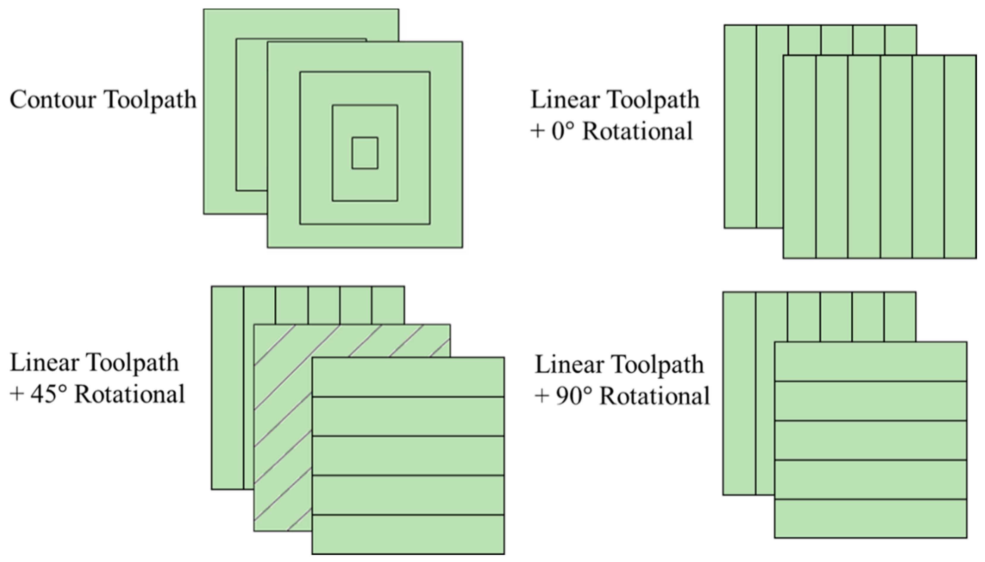
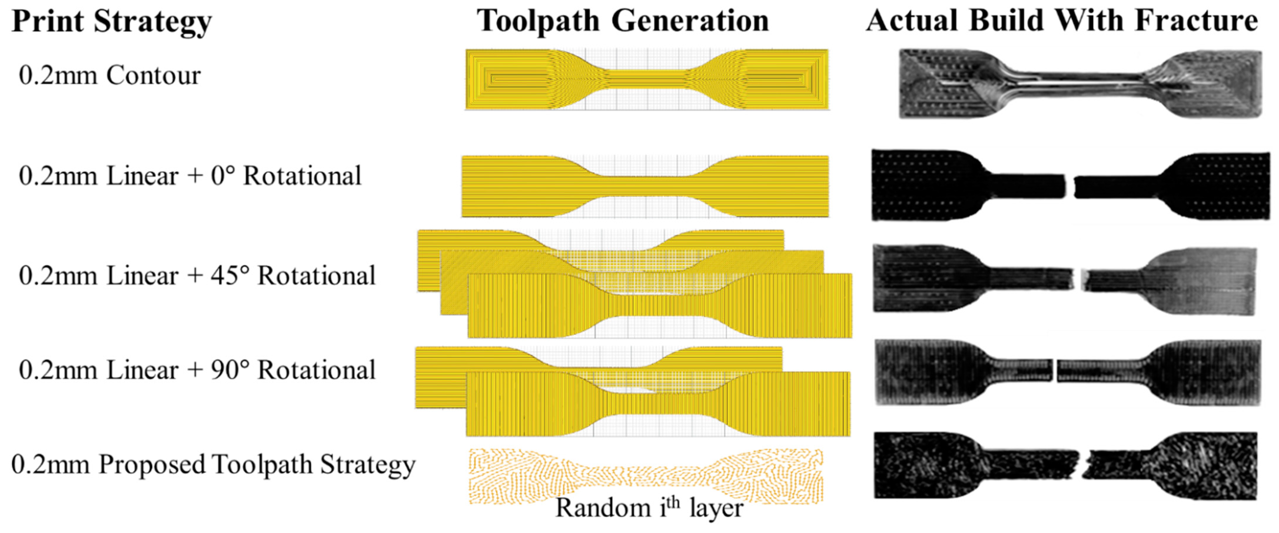
| Toolpath strategies | Linear, Contour, Proposed Toolpath |
| Rotational angle (only for linear) | 0, 45, 90 |
| Printing speed | 30 mm/s |
| Nozzle Temperature | 200 |
| Bed Temperature | 60 |
| Infill Density (linear & contour) | 100% |
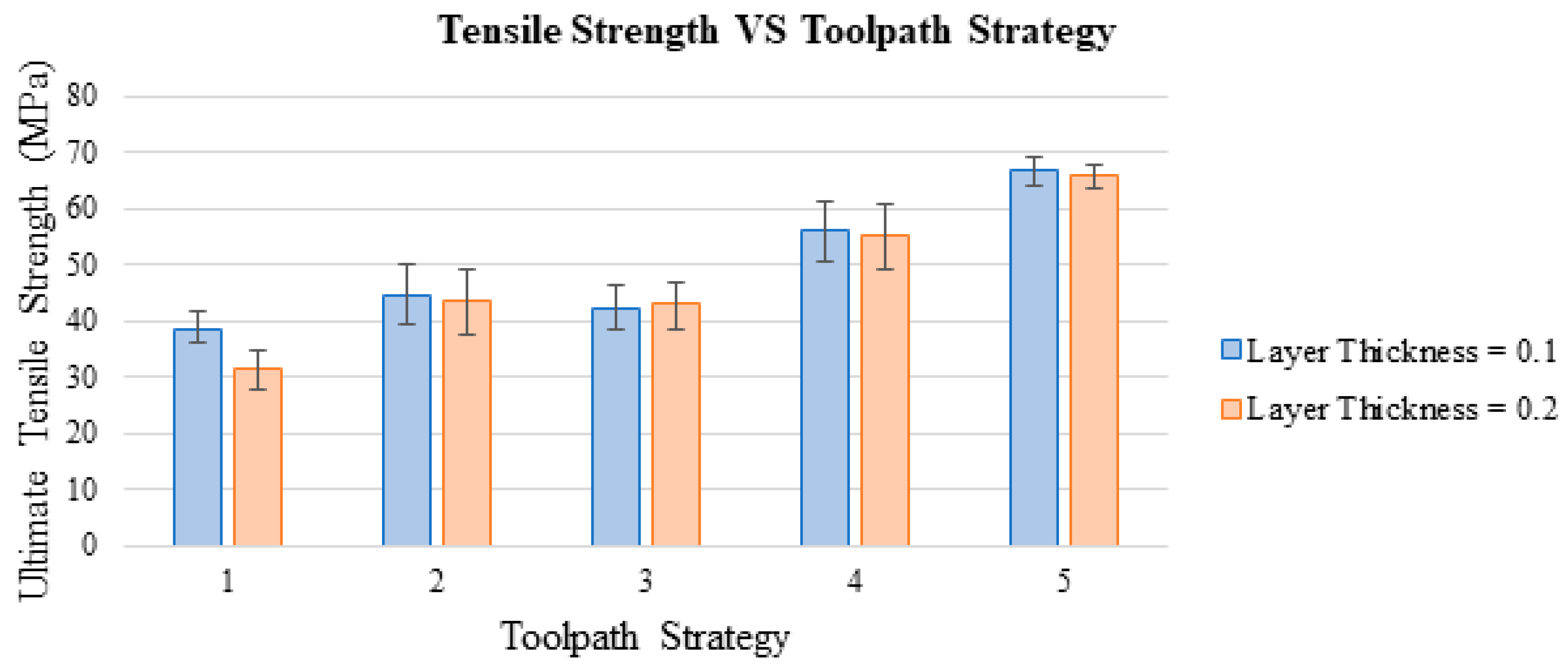
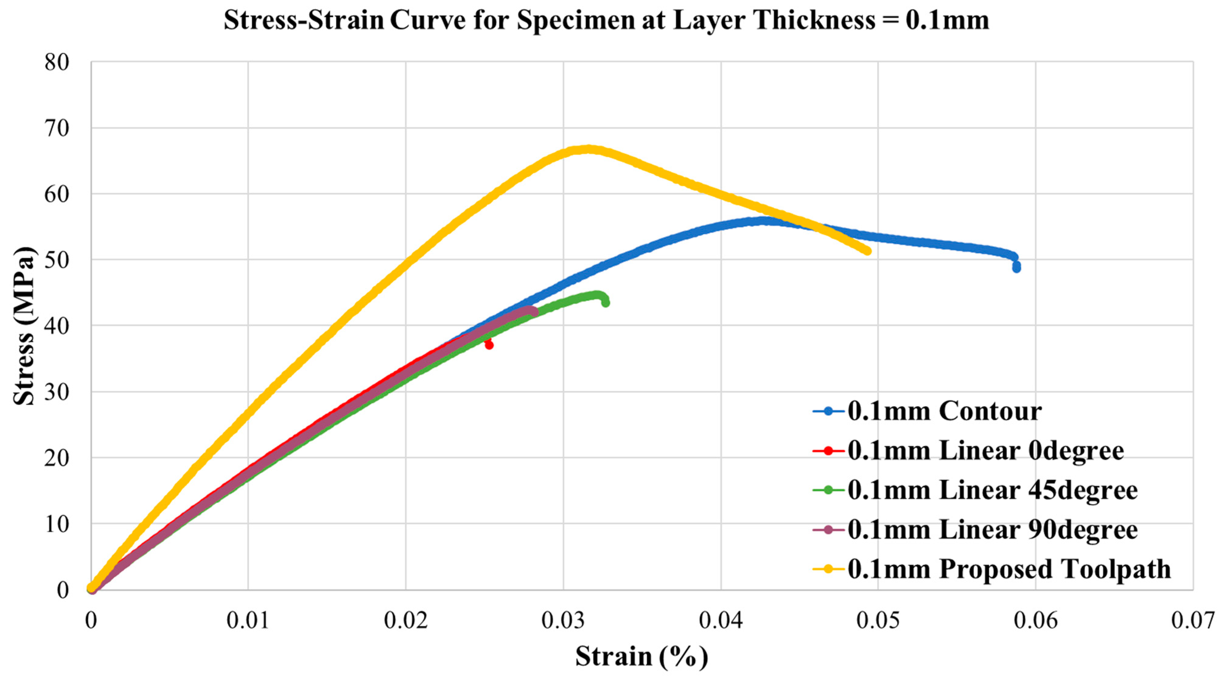
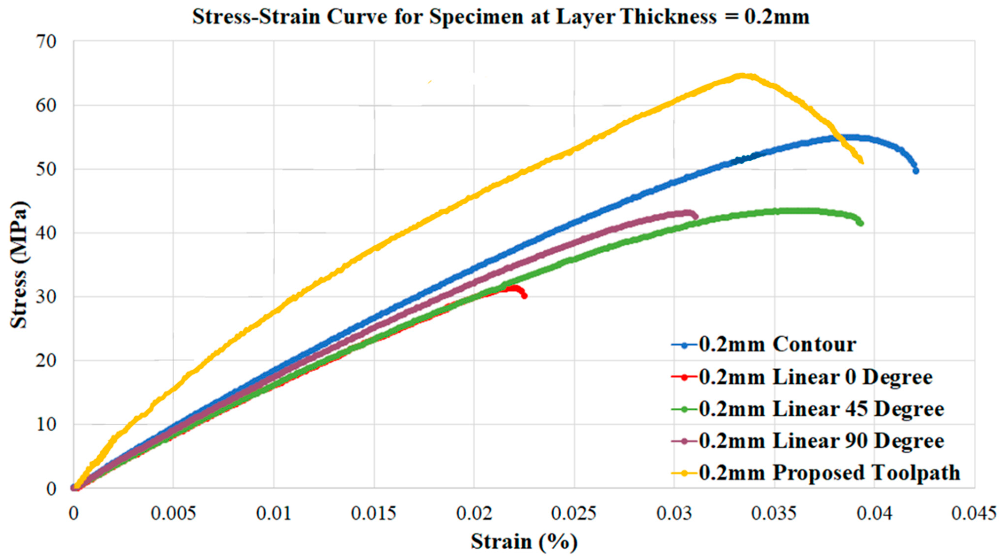
| # | Layer Thickness (mm) | Toolpath Strategy | Rotational Angle (°) | Tensile Strength (MPa) | Young’s Modulus (MPa) | Relative Density |
|---|---|---|---|---|---|---|
| 1 | 0.1 | Linear | 0 | 37.35 | 1580.19 | 0.81 |
| 2 | 0.1 | Linear | 45 | 46.74 | 1394.81 | 0.88 |
| 3 | 0.1 | Linear | 90 | 42.04 | 1515.09 | 0.86 |
| 4 | 0.1 | Contour | N/A | 55.90 | 1331.97 | 0.92 |
| 5 | 0.1 | Proposed Toolpath | N/A | 66.79 | 2154.88 | 0.98 |
| 6 | 0.2 | Linear | 0 | 33.93 | 1393.36 | 0.80 |
| 7 | 0.2 | Linear | 45 | 44.48 | 1243.31 | 0.86 |
| 8 | 0.2 | Linear | 90 | 42.17 | 1388.26 | 0.85 |
| 9 | 0.2 | Contour | N/A | 54.94 | 1449.40 | 0.90 |
| 10 | 0.2 | Proposed Toolpath | N/A | 65.89 | 1911.11 | 0.97 |
| Source | DF | Adj SS | Adj MS | F-Value | p-Value |
|---|---|---|---|---|---|
| Layer Thickness (mm) | 1 | 8.94 | 8.943 | 0.47 | 0.521 |
| Toolpath Strategy | 2 | 1107.40 | 553.699 | 28.82 | 0.001 |
| Error | 6 | 115.26 | 19.210 | ||
| Lack-of-fit | 2 | 1.56 | 0.778 | 0.03 | 0.973 |
| Pure Error | 4 | 113.70 | 28.426 | ||
| Total | 9 | 1231.60 |
Publisher’s Note: MDPI stays neutral with regard to jurisdictional claims in published maps and institutional affiliations. |
© 2021 by the authors. Licensee MDPI, Basel, Switzerland. This article is an open access article distributed under the terms and conditions of the Creative Commons Attribution (CC BY) license (https://creativecommons.org/licenses/by/4.0/).
Share and Cite
Xiao, X.; Roh, B.-M.; Zhu, F. Strength Enhancement in Fused Filament Fabrication via the Isotropy Toolpath. Appl. Sci. 2021, 11, 6100. https://doi.org/10.3390/app11136100
Xiao X, Roh B-M, Zhu F. Strength Enhancement in Fused Filament Fabrication via the Isotropy Toolpath. Applied Sciences. 2021; 11(13):6100. https://doi.org/10.3390/app11136100
Chicago/Turabian StyleXiao, Xinyi, Byeong-Min Roh, and Feng Zhu. 2021. "Strength Enhancement in Fused Filament Fabrication via the Isotropy Toolpath" Applied Sciences 11, no. 13: 6100. https://doi.org/10.3390/app11136100
APA StyleXiao, X., Roh, B.-M., & Zhu, F. (2021). Strength Enhancement in Fused Filament Fabrication via the Isotropy Toolpath. Applied Sciences, 11(13), 6100. https://doi.org/10.3390/app11136100