
Electrospun Metal Oxide Nanofibers and Their Conductometric Gas Sensor Application. Part 2: Gas Sensors and Their Advantages and Limitations


Abstract
1. Introduction
2. Fabrication of Gas Sensors Based on Metal Oxide Nanofibers
2.1. Sensors with Nanofiber Mat
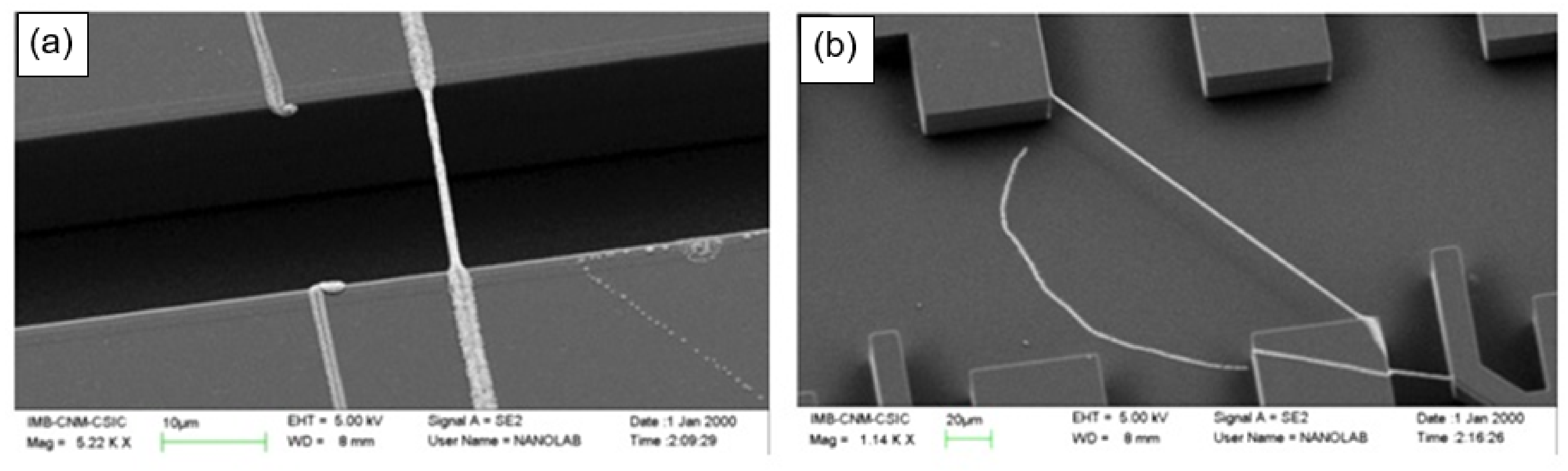
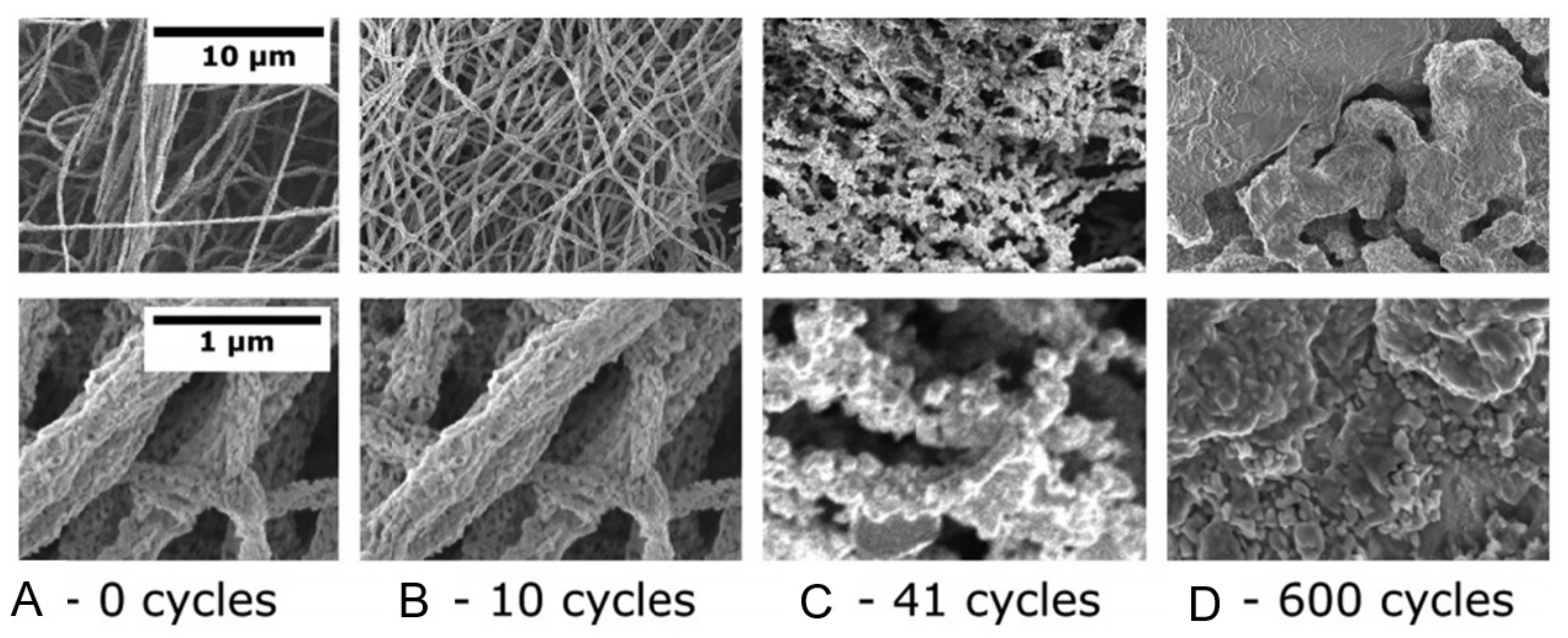
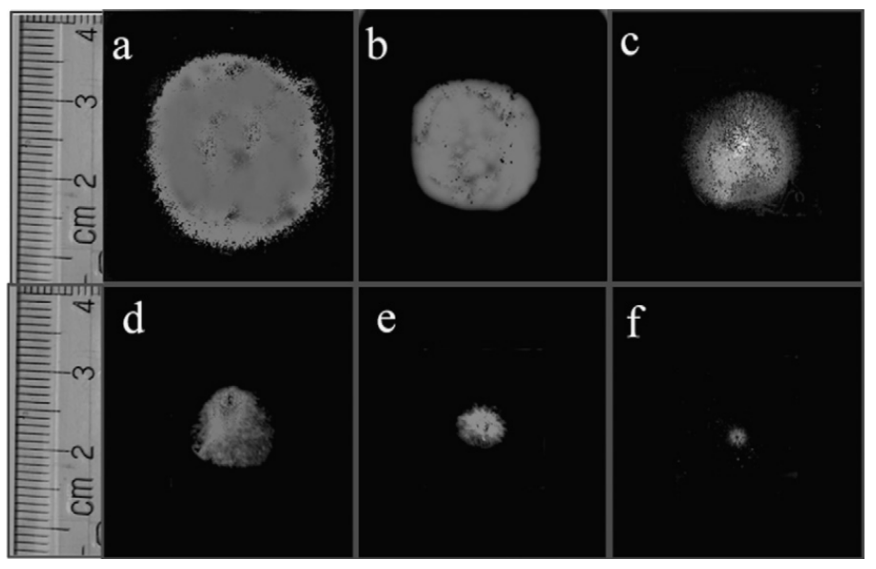
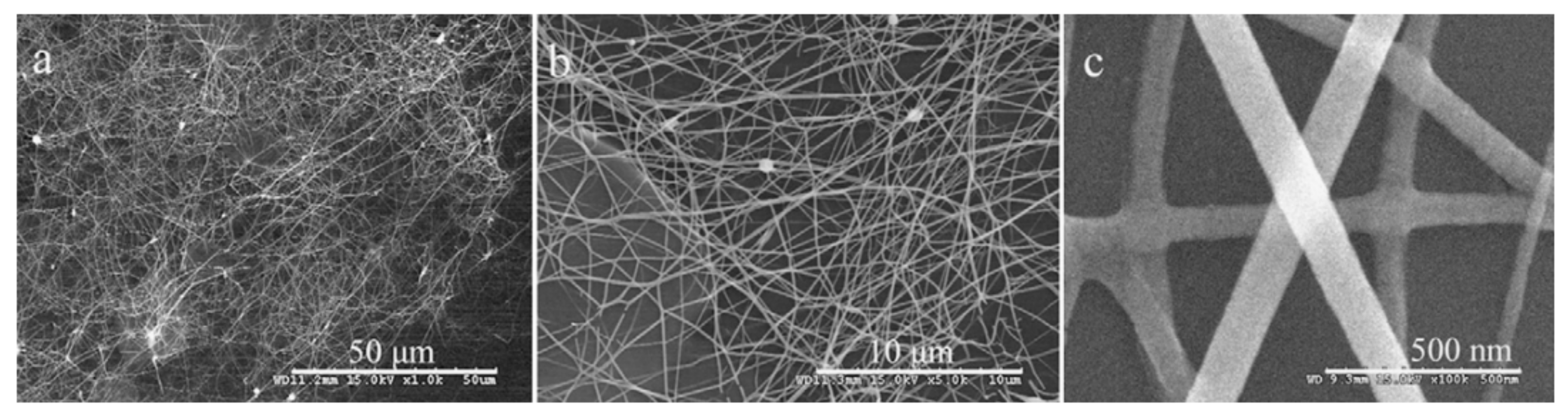
- When manufacturing gas sensors using electrospun nanofibers suspended as bridges between contact areas, it is necessary to keep in mind that the heating rate during sintering of the metal oxide nanofibers is one of the most important factors. For example, Camargo et al. [83] showed that for manufacturing ZnO nanofiber-based bridges, the calcination of electrospun fibers at 600 °C should be carried out at a very low heating rate of ~5 °C/min. At a higher heating rate, the nanofibers were destroyed (see Figure 3). Camargo et al. [83] suggested that it is likely that the forces and mechanics involved during sintering require a slow temperature change.
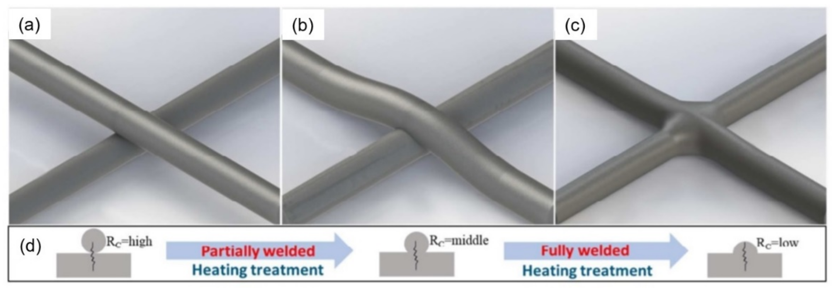
- Formation of low-resistance contacts to nanofibers is a problem of manufacturing nanofiber-based gas sensors no less important than the formation of nanofibers with desired properties. Typically, contacts have increased resistance, which negatively affects the sensor performance. Camargo et al. [83], in order to form low-resistance contacts, used a focused ion beam (FIB)-assisted metal deposition. However, they themselves admit that FIB-assisted technology is a highly time-/money-demanding technique.
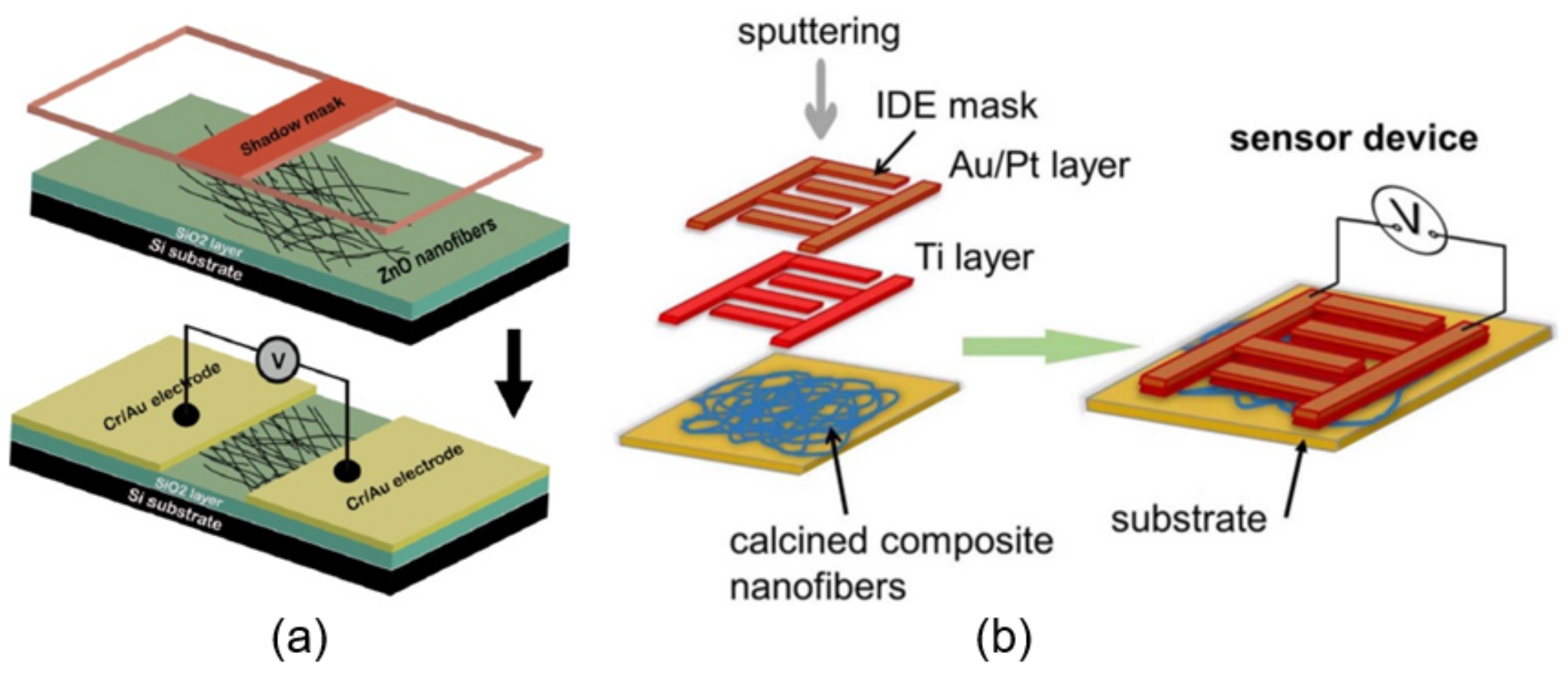
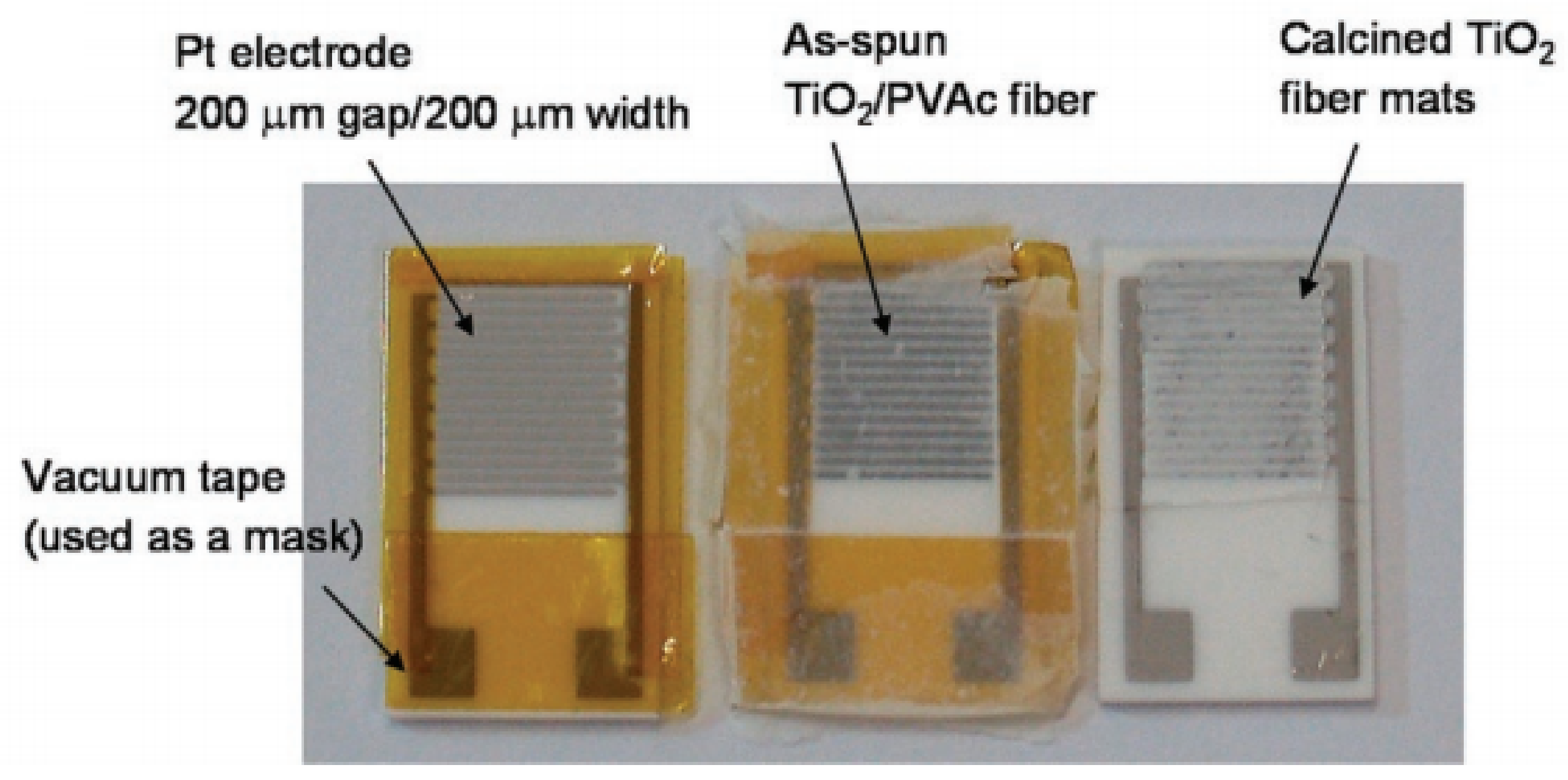
- In the absence of a proven sensor manufacturing technology, the role of the contact configuration increases significantly. Raible et al. [84] found that the contact of fibers with the top or bottom electrodes dramatically alters the response characteristics. In other words, for a better electrical contact, metal electrodes are preferably applied after nanofiber formation.
2.2. Single Nanofiber-Based Sensors
3. Performances of Gas Sensors Based on Metal Oxide Nanofibers
3.1. General Consideration


| Material | Diameter, nm | Analyte Gas | C., ppm | T, oC | Response | Res/Rec Time | Ref. |
|---|---|---|---|---|---|---|---|
| TiO2 | 120–200 | NO2 | 50 | 450 | 30 | 2–4 min/20 s | [151] |
| WO3 | 100 | 0.4 | 75 | 12 | 33 min/38 min | [152] | |
| SnO2 | 200–400 | 50 | 185 | 368 | 400 s/200 s | [153] | |
| SnO2 | 300–500 | 2 | 300 | 81 | 55 s/5 min | [154] | |
| CeO2 | 380 | O2 | 100 | 800 | 1.4 | 30 s/- | [155] |
| La0.67Sr0.33MnO3 | ~126 | 100 | 800 | 1.1 | 53 s/- | [156] | |
| ZnO | 250 | H2 | 10 | 350 | 109 | - | [157] |
| TiO2 | 80 | 125 | 275 | ~6 | 12 s/22 s | [141] | |
| WO3 | 200 | NH3 | 100 | 200 | 6 | 1 s/5 s | [153] |
| ZnO | 95–130 | 100 | 200 | ~20 | - | [147] | |
| TiO2 | 400–500 | CO | 25 | 200 | ~4 | 32–86 s/84–109 s | [158] |
| SnO2 | 200–400 | 500 | 300 | ~4 | 260 s/15 min | [143] | |
| ZnO | 35–150 | 2 | 200 | 1.5 | 168–237 s/270–350 s | [159] | |
| In2O3 | 100 | 100 | 300 | ~5 | - | [160] | |
| WO3 | 275 | Acetone | 50 | 270 | 56 | 6–13 s/4–9 s | [161] |
| ZnO | 145 | 1 | 220 | 7 | 12–17 s/11–23 s | [162] | |
| In2O3 | 250–310 | 5 | 300 | 151 | 5 s/2 s | [163] | |
| α-Fe2O3 | 150–280 | Ethanol | 100 | 300 | 2 | 3 s/5 s | [164] |
| SnO2 | 100 | 10 | 330 | 5 | 13 s/13.9 s | [105] | |
| In2O3 | 160–200 | 1500 | 300 | 379 | 1 s/5 s | [165] | |
| In2O3 | 30–100 | 30 | 220 | ~4 | 6 s/10 s | [166] | |
| Co3O4 | 100–200 | 100 | 301 | 51 | 8–23 s/59–3 s | [167] | |
| ZnO | 500–600 | DMF | 100 | RT | 13 | 32 s/17 s | [168] |
| In2O3 | 150–200 | 100 | 340 | 3 | 18 s/17 s | [169] |
| Sample | Heating Rate, °C/min | Surface Area, m2/g | Pore Size, nm | Crystallite Size, nm |
|---|---|---|---|---|
| WO3-1 | 1 | 10.7 | 11.2 | 26.5 |
| WO3-5 | 5 | 14.4 | 17.5 | 20.9 |
| WO3 10 | 10 | 16.4 | 30.6 | 16.8 |
| WO3-15 | 15 | 12.8 | 18.5 | 16.1 |
3.2. Hollow Nanofiber-Based Gas Sensors
3.3. Surface Modification or Surface Decoration of Metal Oxide Nanofibers
Mechanisms of Surface Modification Influence on Gas Sensor Performances
| Material | Dopant | Analyte gas | C, ppm | T, (°C) | Response | Detection Limit | Res./Rec. Time, s | Ref. |
|---|---|---|---|---|---|---|---|---|
| SnO2 | Pd | Acetone | 100 | 275 | 99 | 1 ppm | - | [209] |
| SnO2 | Formaldehyde | 100 | 160 | 19 | - | 2/7 | [210] | |
| In2O3 | Ethanol | 50 | 200 | 18 | 1 ppm | 1/10 | [130] | |
| ZnO | CO | 20 | 220 | 5.5 | 1 ppm | 27/15 | [211] | |
| TiO2 | NO2 | 2.1 | 180 | 38 | 0.16 ppm | - | [212] | |
| WO3 | H2S | 1 | 350 | 1.4 | 1 ppm | - | [213] | |
| WO3 | Toluene | 1 | 350 | 5.5 | 20 ppb | 119/16 | [213] | |
| WO3 | Pt | Acetone | 2 | 350 | 4 | 120 ppb | - | [214] |
| α-Fe2O3 | H2S | 10 | 175 | 157 | - | [215] | ||
| NiO | Ethanol | 100 | 400 | 12 | 1 ppm | - | [216] | |
| In2O3 | H2S | 600 | 200 | 1490 | 50 ppm | 60/120 | [196] | |
| SnO2 | H2S | 20 | 300 | 5100 | - | - | [192] | |
| SnO2 | Toluene | 10 | 300 | 12 | 1 ppm | - | [217] | |
| SnO2 | Ag | Acetone | 200 | 160 | 117 | 5 ppm | 6/10 | [218] |
| TiO2 | H2S | 1 | 350 | 120 | 1 ppm | - | [219] | |
| In2O3 | Formaldehyde | 50 | 115 | 28 | 5 ppm | 5/10 | [220] | |
| SnO2 | Au | CO | 10 | 300 | 19 | 1 ppm | - | [221] |
| SnO2 | CO | 5 | 300 | 84 | - | 22/235 | [189] | |
| In2O3 | Ethanol | 500 | 140 | 14 | 50 ppm | 12/24 | [222] | |
| WO3 | n-butanol | 100 | 250 | 230 | 1 ppm | 5–43/10–122 | [223] |
3.4. Doping of Metal Oxide Nanofibers
Influencing Mechanism of Nanofiber Doping
3.5. Heterostructures and Core–Shell Structures in Nanofiber-Based Gas Sensors
| Metal Oxide | Addition | Solubility Limit | Ref. |
|---|---|---|---|
| SnO2 | In | 4–10% | [263,264] |
| Mn | ~5–6% | [265] | |
| Fe; Ni; V; Mo | <5% | [241,266,267,268,269,270] | |
| Nb | ~3% | [271] | |
| Co; Cr | ~0.5–3% | [272,273,274] | |
| Cu; Al | <1% | [243,275] | |
| Si | 1% | [276] | |
| In2O3 | Fe | ~20% | [277,278] |
| Ga | 10–12% | [279] | |
| Sn | ~8% | [263,280,281] | |
| Nb; Mo | 1–3% | [282,283,284] | |
| Co | ~1% | [285] | |
| Cu | <<1% | [286,287] | |
| ZnO | Co, Mn | 13–30% | [288,289] |
| Fe | 2–20% | [288,290] | |
| V | 3–15% | [289,290] | |
| Sn | 4–8% | [291] | |
| Cr | ~6% | [290] | |
| Ni, Ti | ~3% | [288,290] | |
| Al | 0.3–2.0% | [292,293] | |
| In | <1% | [294] | |
| Ga | 0.5% | [293] | |
| Cu | <0.2% | [290] |
| Material | Gas | Conc. (ppm) | T, (°C) | Response (Ra/Rg) | Ref. |
|---|---|---|---|---|---|
| TiO2–ZnO | O2 | 10,000 | 300 | 20 | [295] |
| ZnO–rGO | NO2 | 5 | 400 | 119 | [79] |
| p-In2O3–TiO2 | NOx | 97 | 25 | 40 | [296] |
| Al2O3–In2O3 | 97 | 25 | 100 | [254] | |
| CuO–In2O3 | H2S | 5 | RT | 9170 | [297] |
| CuO-SnO2 | 10 | 300 | 25799 | [170] | |
| ZnO–CuO | 10 | 150 | 4490 | [298] | |
| SnO2–CeO2 | 20 | 210 | 90 | [240] | |
| CuO–ZnO | CO | 0.1 | 300 | 7 | [299] |
| SnO2–RGO | 1 | 200 | 10 | [300] | |
| TiO2–ZnO | 0.1 | 375 | 15 | [301] | |
| SnO2–ZnO | 10 | 350 | 11 | [302] | |
| SnO2–MWCNT | 50 | 25 | 1.3 | [303] | |
| p-NiO–n-SnO2 | H2 | 100 | 320 | 13 | [304] |
| In2-xNixO3 | C2H5OH | 100 | 180 | 80 | [305] |
| Cr2O3–ZnO | 100 | 300 | 24 | [116] | |
| In2O3–ZnO | 100 | 210 | 25 | [306] | |
| ZnO–In2O3–ZnO | 100 | 210 | 17 | [306] | |
| Sn-SnO2–Carbon | 500 | 240 | 30 | [307] | |
| ZnO-TiO2 | 500 | 320 | 51 | [258] | |
| SnO2–ZnO | CH3OH | 10 | 350 | 8.5 | [308] |
| In2O3–WO3 | C3H6O | 0.8 | 350 | 1.8 | [252] |
| SnO2–α-Fe2O3 | 100 | 340 | 31 | [309] | |
| In2O3–WO3 | 0.4 | 275 | 1.3 | [252] | |
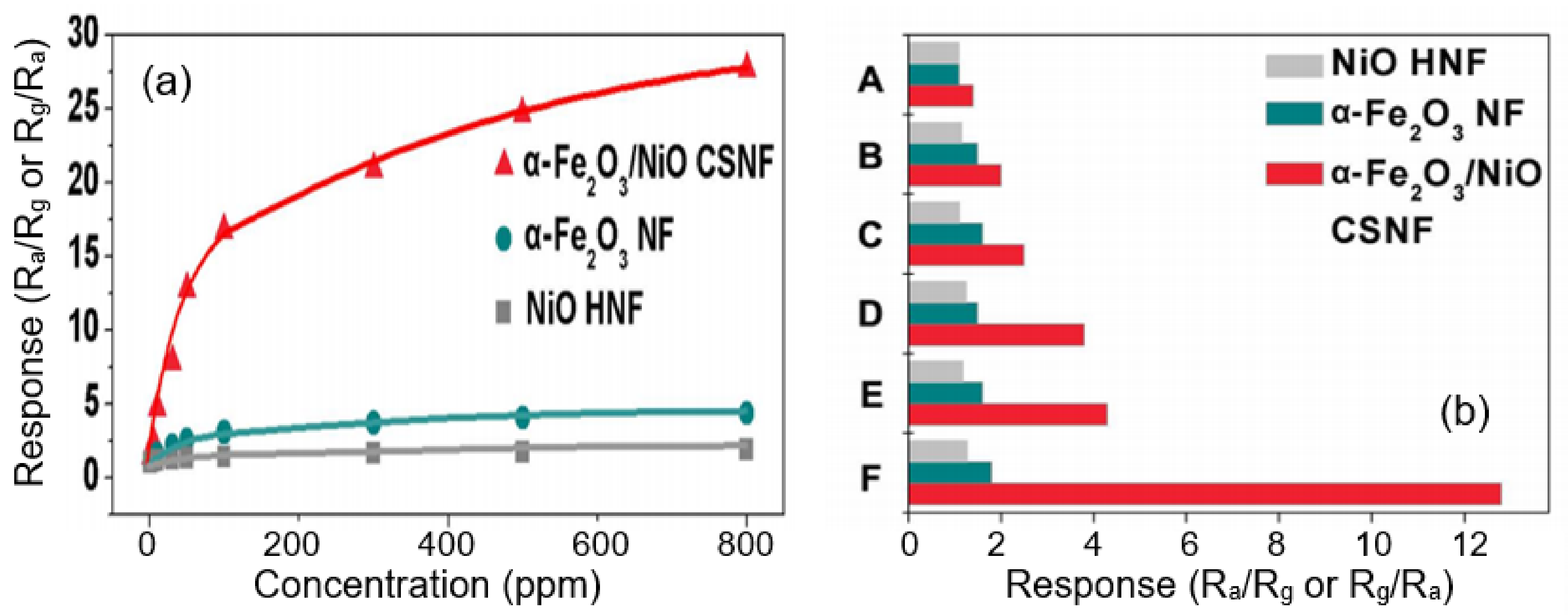
| α-Fe2O3–NiO | CH2O | 50 | 240 | 13 | [255] |
| NiO–SnO2 | 10 | 200 | 6.3 | [310] | |
| SnO2–In2O3 | 0.5 | 375 | 2.2 | [311] | |
| SnO2–In2O3 | 50 | 300 | 115 | [257] | |
| PPy–WO3 | NH3 | 20 | 100 | 26 | [312] |
| SnO2–In2O3 | 1 | 25 | 21 | [261] | |
| PANI–TiO2 | 0.025 | 25 | 0.4 | [313] | |
| p-La0.67Sr0.33MnO3–n-CeO2 | C3H8 | 20 | 800 | 75 | [238] |
| NiO-SnO2 | C7H8 | 50 | 330 | 11 | [314] |
| La0.7Sr0.3FeO3–In2O3-SnO2 | C3H9N | 1 | 80 | 8 | [315] |
| p-NiO–n-ZnO | 100 | 260 | 892 | [316] | |
| ZnO–In2O3 | 5 | 375 | 119 | [317] |
3.6. Post-Treatments of Nanofibers
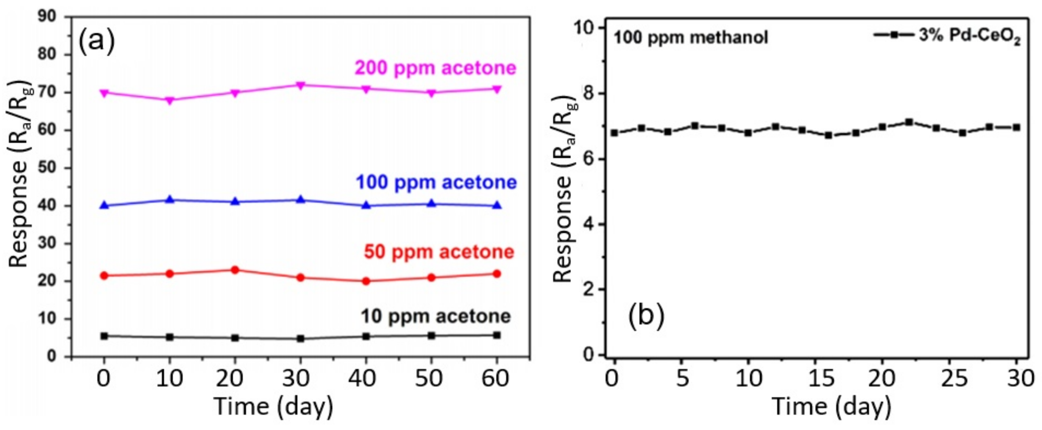
3.7. Stability of Nanofiber-Based Gas and Humidity Sensors
4. Limitations of Electrospinning for Gas Sensor Design and Approaches to Resolving These Problems
- First, according to Mondal and Sharma [344], some of the disadvantages of electrospinning technology are (a) the need to use a templating carrier polymer, since direct electrospinning is not possible for all metal oxides, and (b) the limited number of polymers that can be used for the production of metal oxide nanofibers by electrospinning.
- Second, the variety of applications and performances of electrospun metal oxide nanofibers is limited due to their brittleness after calcination [345]. In particular, electrospun metal oxide nanofibers after calcination cannot be used in the development of sensors based on flexible substrates. However, conventional metal oxide conductometric gas sensors have the same limitation.
- Third, nanofibers have poor adhesion to the substrate. Electrospun fibers are also characterized by the poor interfacial adhesion properties between the nanofibers. It is known that the mat of electrospun nanofibers consists of fibers with a weak inter-fiber interaction. As a result, such a network of nanofibers has reduced mechanical properties and a high contact resistance.

- Fourth, to date, it remains a challenge to produce nanofibers with diameters smaller than 20–50 nm by the existing electrospinning technique.
- Sixth, the complexity of fabrication also creates certain difficulties in using electrospinning technology to form gas-sensitive layers on the sensor platform. This also includes the impossibility of forming gas-sensitive layers localized in certain places of the platforms of gas sensors by this method.
- (i)
- Substantial reduction in the applied voltage;
- (ii)
- The ability to accurately position the fibers over a relatively large area with minimal material consumption;
- (iii)
- Seventh, the low production rate is another important disadvantage of this method. Therefore, the major task after success in laboratories is to optimize the electrospinning process in order to increase productivity.
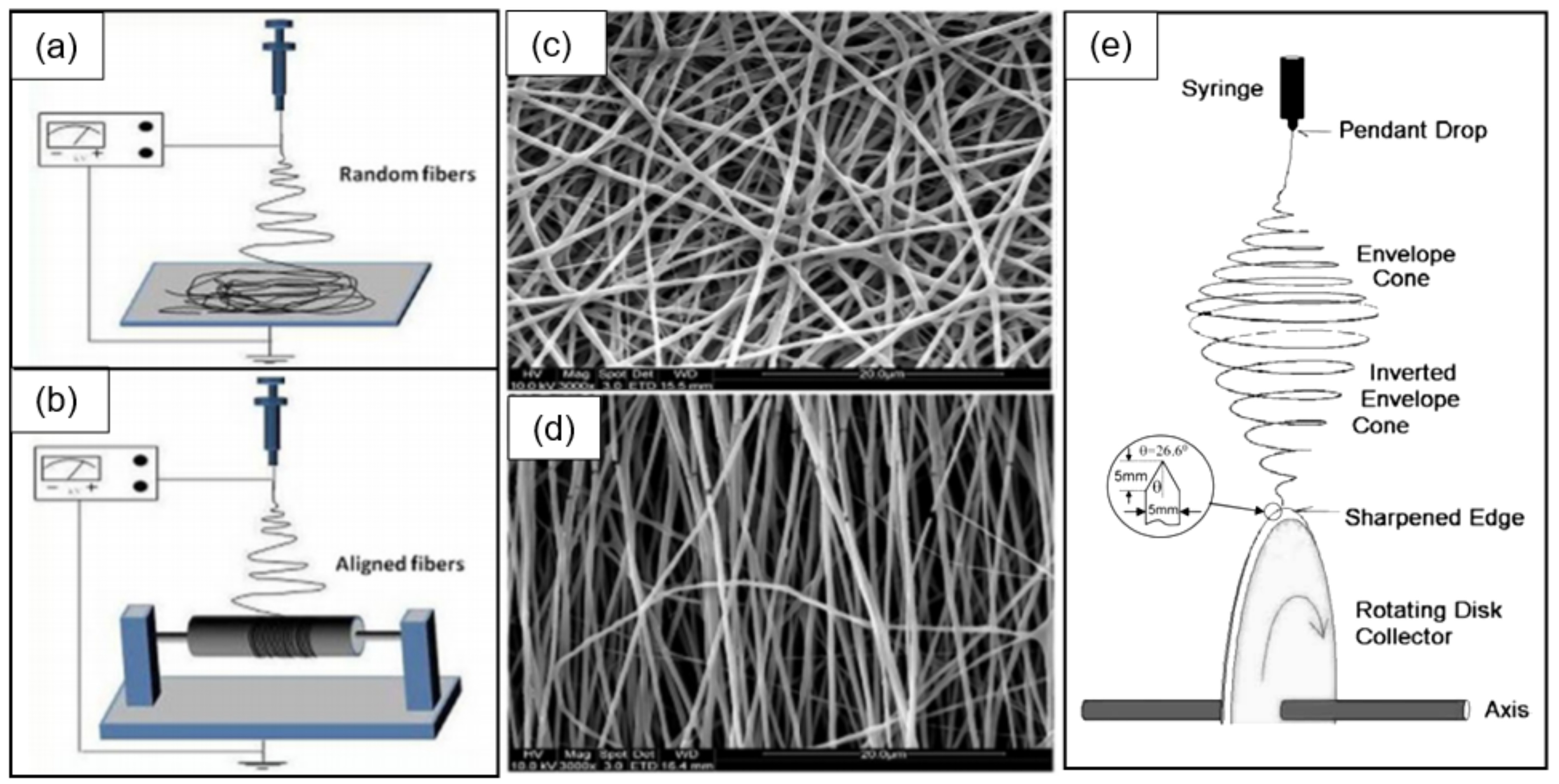
- Eighth, electrospun nanofibers are mostly randomly oriented (see Figure 26, Figure 28 and Figure 33), which significantly limits the ability to obtain the required repeatability of the final structures of nanofiber mats [371]. In this case, due to the arbitrary position of nanofibers on the surface of the substrates, the fewer fibers there are in the coating, the lower the repeatability of the fiber mat structure.
- Ninth, and most importantly, electrospinning technology is incompatible with traditional mass production processes.
5. Summary
Funding
Institutional Review Board Statement
Informed Consent Statement
Data Availability Statement
Acknowledgments
Conflicts of Interest
References
- Zhou, Z.; Lan, C.; Wei, R.; Ho, J.C. Transparent metal-oxide nanowires and their applications in harsh electronics. J. Mater. Chem. C 2019, 7, 202–217. [Google Scholar] [CrossRef]
- Scheideler, W.; Subramanian, V. Printed flexible and transparent electronics: Enhancing low-temperature processed metal oxides with 0D and 1D nanomaterials. Nanotechnology 2019, 30, 272001. [Google Scholar] [CrossRef]
- Bagga, S.; Akhtar, J.; Mishra, S. Synthesis and applications of ZnO nanowire: A review. AIP Conf. Proc. 2018, 1989, 020004. [Google Scholar]
- Chen, C.; Fan, Y.; Gu, J.; Wu, L.; Passerini, S.; Mai, L. One-dimensional nanomaterials for energy storage. J. Phys. D Appl. Phys. 2018, 51, 113002. [Google Scholar] [CrossRef]
- Hahm, J.-I. Fundamental properties of one-dimensional zinc oxide nanomaterials and implementations in various detection modes of enhanced biosensing. Annu. Rev. Phys. Chem. 2016, 67, 691–717. [Google Scholar] [CrossRef]
- Weng, B.; Liu, S.; Tang, Z.-R.; Xu, Y.-J. One-dimensional nanostructure based materials for versatile photocatalytic applications. RSC Adv. 2014, 4, 12685–12700. [Google Scholar] [CrossRef]
- Pan, J.; Shen, H.; Mathur, S. One-dimensional SnO2 nanostructures: Synthesis and applications. J. Nanotechnol. 2012, 2012, 917320. [Google Scholar] [CrossRef]
- Devan, R.S.; Patil, R.A.; Lin, J.-H.; Ma, Y.-R. One-dimensional metal-oxide nanostructures: Recent developments in synthesis, characterization, and applications. Adv. Funct. Mater. 2012, 22, 3326–3370. [Google Scholar] [CrossRef]
- Zhai, T.; Fang, X.; Liao, M.; Xu, X.; Zeng, H.; Yoshio, B.; Golberg, D. A Comprehensive review of one-dimensional metal-oxide nanostructure photodetectors. Sensors 2009, 9, 6504–6529. [Google Scholar] [CrossRef]
- Xia, Y.; Yang, P.; Sun, Y.; Wu, Y.; Mayers, B.; Gates, B.; Yin, Y.; Kim, F.; Yan, H. One-dimensional nanostructures: Synthesis, characterization, and applications. Adv. Mater. 2003, 15, 353–389. [Google Scholar] [CrossRef]
- Wang, X.; Ding, B.; Yu, J.; Wang, M. Engineering biomimetic superhydrophobic surfaces of electrospun nanomaterials. Nano Today 2011, 6, 510–530. [Google Scholar] [CrossRef]
- Imran, M.; Motta, N.; Shafiei, M. Electrospun one-dimensional nanostructures: A new horizon for gas sensing materials. Beilstein J. Nanotechnol. 2018, 9, 2128–2170. [Google Scholar] [CrossRef] [PubMed]
- Nasiri, N.; Clarke, C. Nanostructured chemiresistive gas sensors for medical applications. Sensors 2019, 19, 462. [Google Scholar] [CrossRef]
- Zhang, S.; Jia, Z.; Liu, T.; Wei, G.; Su, Z. Electrospinning nanoparticles-based materials interfaces for sensor applications. Sensors 2019, 19, 3977. [Google Scholar] [CrossRef] [PubMed]
- Kolmakov, A.; Moskovits, M. Chemical sensing and catalysis by one dimensional metal-oxide nanostructures. Ann. Rev. Mater. Res. 2004, 34, 151–180. [Google Scholar] [CrossRef]
- Chen, P.-C.; Shen, G.; Zhou, C. Chemical sensors and electronic noses based on 1-D metal oxide nanostructures. IEEE Trans. Nanotechnol. 2008, 7, 668–682. [Google Scholar] [CrossRef]
- Morante, J.R. Chemical to electrical transduction mechanisms from single metal oxide nanowire measurements: Response time constant analysis. Nanotechnology 2013, 24, 444004. [Google Scholar] [CrossRef]
- Chen, X.; Wong, C.K.Y.; Yuan, C.A.; Zhang, G. Nanowire-based gas sensors. Sens. Actuators B Chem. 2013, 177, 178–195. [Google Scholar] [CrossRef]
- Ramgir, N.; Datta, N.; Kaur, M.; Kailasaganapathi, S.; Debnath, A.K.; Aswal, D.K.; Gupta, S.K. Metal oxide nanowires for chemiresistive gas sensors: Issues, challenges and prospects. Colloids Surf. A 2013, 439, 101–116. [Google Scholar] [CrossRef]
- Comini, E. Metal oxide nanowire chemical sensors: Innovation and quality of life. Mater. Today 2016, 19, 559–567. [Google Scholar] [CrossRef]
- Lee, J.-H.; Mirzaie, A.; Kim, J.-Y.; Kim, J.-H.; Kim, H.W.; Kim, S.K. Optimization of the surface coverage of metal nanoparticles on nanowires gas sensors to achieve the optimal sensing performance. Sens. Actuators B Chem. 2020, 302, 127196. [Google Scholar] [CrossRef]
- Wang, Y.; Duan, L.; Deng, Z.; Liao, J. Electrically transduced gas sensors based on semiconducting metal oxide nanowires. Sensors 2020, 20, 6781. [Google Scholar] [CrossRef] [PubMed]
- Korotcenkov, G. Current trends in nanomaterials for metal oxide-based conductometric gas sensors: Advantages and limitations. Part 1: 1D and 2D nanostructures. Nanomaterials 2020, 10, 1392. [Google Scholar] [CrossRef] [PubMed]
- Korotcenkov, G. Electrospun metal oxide nanofibers and its conductometric gas sensor application. Part 1: Nanofibers and features of their forming. Nanomaterials 2021, 11, 1544. [Google Scholar] [CrossRef]
- Ding, B.; Wang, M.; Wang, X.; Yu, J.; Sun, G. Electrospun nanomaterials for ultrasensitive sensors. Mater. Today 2010, 13, 16–27. [Google Scholar] [CrossRef]
- Choi, S.-J.; Persano, L.; Camposeo, A.; Jang, J.-S.; Koo, W.-T.; Kim, S.-J.; Cho, H.-J.; Kim, I.-D.; Pisignano, D. Electrospun nanostructures for high performance chemiresistive and optical sensors. Macromol. Mater. Eng. 2017, 302, 1600569. [Google Scholar] [CrossRef]
- Vuong, N.M.; Jung, H.; Kim, D.; Kim, H.; Hong, S.-K. Realization of an open space ensemble for nanowires: A strategy for the maximum response in resistive sensors. J. Mater. Chem. 2012, 22, 6716–6725. [Google Scholar] [CrossRef]
- Korotcenkov, G. The role of morphology and crystallographic structure of metal oxides in response of conductometric-type gas sensors. Mater. Sci. Eng. Rep. 2008, 61, 1–39. [Google Scholar] [CrossRef]
- Yamazoe, N. New approaches for improving semiconductor gas sensors. Sens. Actuators B Chem. 1991, 5, 7–19. [Google Scholar] [CrossRef]
- Barsan, N.; Weimar, U. Conduction model of metal oxide gas sensors. J. Electroceram. 2001, 7, 143–16746. [Google Scholar] [CrossRef]
- Korotcenkov, G. Metal oxides for solid state gas sensors: What determines our choice? Mater. Sci. Eng. B 2007, 139, 1–23. [Google Scholar] [CrossRef]
- Yamazoe, N.; Shimanoe, K. Receptor function and response of semiconductor gas sensor. J. Sens. 2009, 2009, 875704. [Google Scholar] [CrossRef]
- Yamazoe, N.; Fuchigami, J.; Kishikawa, M.; Seiyama, T. Interactions of tin oxide surface with O2, H2O and H2. Surf. Sci. 1979, 86, 335–344. [Google Scholar] [CrossRef]
- Morrison, S.R. Selectivity in semiconductor gas sensor. Sens. Actuators 1987, 12, 425–440. [Google Scholar] [CrossRef]
- Kohl, D. The role of noble-metals in the chemistry of solid-state gas sensors. Sens. Actuators B Chem. 1990, 1, 158–165. [Google Scholar] [CrossRef]
- Xu, C.N.; Tamaki, J.; Miura, N.; Yamazoe, N. Grain-size effects on gas sensitivity of porous SnO2-based elements. Sens. Actuators B Chem. 1991, 3, 147–155. [Google Scholar] [CrossRef]
- Kupriyanov, L.Y. (Ed.) Semiconductor Sensors in Physico-Chemical Studies; Elsevier: Amsterdam, The Netherlands, 1992; p. 400. [Google Scholar]
- Sberveglieri, G. (Ed.) Gas Sensors; Springer: Amsterdam, The Netherlands, 1992; p. 409. [Google Scholar]
- Williams, D.E.; Henshaw, G.S.; Pratt, K.F.E.; Peat, R. Reaction-diffusion effects and systematic design of gas sensitive resistors based on semiconducting oxides. J. Chem. Soc. Faraday Trans. 1995, 91, 4299–4307. [Google Scholar] [CrossRef]
- Williams, D.E. Semiconducting oxides as gas-sensitive resistors. Sens. Actuators B Chem. 1999, 57, 1–16. [Google Scholar] [CrossRef]
- Brynzari, V.; Korotchenkov, G.; Dmitriev, S. Simulation of thin film gas sensor kinetics. Sens. Actuators B Chem. 1999, 61, 143–153. [Google Scholar] [CrossRef]
- Brynzari, V.; Korotchenkov, G.; Dmitriev, S. Theoretical study of semiconductor thin film gas sensitivity: Attempt to consistent approach. J. Electron. Technol. 2000, 33, 225–235. [Google Scholar]
- Hahn, S.H.; Barsan, N.; Weimar, U.; Ejakov, S.G.; Visser, J.H.; Soltis, R.E. CO sensing with SnO2 thick film sensors: Role of oxygen and water vapour. Thin Solid Film. 2003, 436, 17–24. [Google Scholar] [CrossRef]
- Batzill, M. Surface science studies of gas sensing materials: SnO2. Sensors 2006, 6, 1345–1366. [Google Scholar] [CrossRef]
- Gurlo, A. Interplay between O2 and SnO2: Oxygen ionosorption and spectroscopic evidence for adsorbed oxygen. ChemPhysChem 2006, 7, 2041–2052. [Google Scholar] [CrossRef] [PubMed]
- Korotcenkov, G.; Blinov, I.; Stetter, J.R. Kinetics of indium oxide-based thin film gas sensor response: The role of “redox” and adsorption/desorption processes in gas sensing effects. Thin Solid Film. 2007, 515, 3987–3996. [Google Scholar] [CrossRef]
- Korotcenkov, G.; Brinzari, V.; Stetter, J.R.; Blinov, I.; Blaja, V. The nature of processes controlling the kinetics of indium oxide-based thin film gas sensor response. Sens. Actuators B Chem. 2007, 128, 51–63. [Google Scholar] [CrossRef]
- Batzill, M.; Diebold, U. Surface studies of gas sensing metal oxides. Phys. Chem. Chem. Phys. 2007, 9, 2307–2318. [Google Scholar] [CrossRef] [PubMed]
- Barsan, N.; Koziej, D.; Weimar, U. Metal oxide-based gas sensor research: How to? Sens. Actuators B Chem. 2007, 121, 18–35. [Google Scholar] [CrossRef]
- Gurlo, A.; Riedel, R. In situ and operando spectroscopy for assessing mechanisms of gas sensing. Angew. Chem. Int. Ed. 2007, 46, 3826–3848. [Google Scholar] [CrossRef] [PubMed]
- Rumyantseva, M.N.; Gas’kov, A.M. Chemical modification of nanocrystalline metal oxides: Effect of the real structure and surface chemistry on the sensor properties. Russ. Chem. Bull. 2008, 57, 1106–1125. [Google Scholar] [CrossRef]
- Brinzari, V.; Ivanov, M.; Cho, B.K.; Kamei, M.; Korotcenkov, G. Photoconductivity in In2O3 nanoscale thin films: Interrelation with chemisorbed-type conductometric response towards oxygen. Sens. Actuators B Chem. 2010, 148, 427–438. [Google Scholar] [CrossRef]
- Barsan, N.; Simion, C.; Heine, T.; Pokhrel, S.; Weimar, U. Modeling of sensing and transduction for p-type semiconducting metal oxide based gas sensors. J. Electroceram. 2010, 25, 11–19. [Google Scholar] [CrossRef]
- Yamazoe, N.; Shimanoe, K. Basic approach to the transducer function of oxide semiconductor gas sensors. Sens. Actuators B Chem. 2011, 160, 1352–1362. [Google Scholar] [CrossRef]
- Korotcenkov, G.; Cho, B.K. The role of grain size on the thermal stability of nanostructured metal oxides used in gas sensor applications and approaches for grain-size stabilization. Prog. Crystal. Growth 2012, 58, 167–208. [Google Scholar] [CrossRef]
- Korotcenkov, G. (Ed.) Chemical Sensors: Simulation and Modeling. Volume 2: Conductometric Gas Sensor; Momentum Press: New York, NY, USA, 2012. [Google Scholar]
- Korotcenkov, G. (Ed.) Chemical Sensors: Simulation and Modeling. Volume 1: Microstructural Characterization and Modeling of Metal Oxides; Momentum Press: New York, NY, USA, 2012. [Google Scholar]
- Kim, H.J.; Lee, J.-H. Highly sensitive and selective gas sensors using p-type oxide semiconductors: Overview. Sens. Actuators B Chem. 2014, 192, 607–627. [Google Scholar] [CrossRef]
- Korotcenkov, G.; Brinzari, V.; Cho, B.K. In2O3 and SnO2 based ozone sensors: Fundamentals. J. Sens. 2016, 2016, 3816094. [Google Scholar] [CrossRef]
- Korotcenkov, G.; Cho, B.K. Metal oxide based composites in conductometric gas sensors: Achievements and challenges. Sens. Actuators B Chem. 2017, 244, 182–210. [Google Scholar] [CrossRef]
- Brinzari, V.; Korotcenkov, G. Kinetic approach to receptor function in chemiresistive gas sensor modeling of tin dioxide. Steady state consideration. Sens. Actuators B Chem. 2018, 259, 443–454. [Google Scholar] [CrossRef]
- Barsan, N.; Schierbaum, K. (Eds.) Gas Sensors Based on Conducting Metal Oxides; Elsevier Metal Oxide Series edited by Korotcenkov, G. Elsevier: Cambridge, MA, USA, 2018. [Google Scholar]
- Korotcenkov, G. Handbook of Humidity Measurement: Methods, Materials and Technologies. Volume 2: Electronic and Electrical Humidity Sensors; CRC Press: Boca Raton, FL, USA, 2019. [Google Scholar]
- Jaaniso, R.; Tan, O.K. (Eds.) Semiconductor Gas Sensors; Woodhead Publishing: Cambridge, UK, 2020. [Google Scholar]
- Abideen, Z.U.; Kim, J.-H.; Lee, J.-H.; Kim, J.-Y.; Mirzaei, A.; Kim, H.W.; Kim, S.S. Electrospun metal oxide composite nanofibers gas sensors: A review. J. Korean Ceram. Soc. 2017, 54, 366–379. [Google Scholar] [CrossRef]
- Wang, X.; Drew, C.; Lee, S.-H.; Senecal, K.J.; Kumar, J.; Samuelson, L.A. Electrospun nanofibrous membranes for highly sensitive optical sensors. Nano Lett. 2002, 2, 1273–1275. [Google Scholar] [CrossRef]
- Ding, B.; Kim, J.; Miyazaki, Y.; Shiratori, S. Electrospun nanofibrous membranes coated quartz crystal microbalance as gas sensor for NH3 detection. Sens. Actuators B Chem. 2004, 101, 373–380. [Google Scholar] [CrossRef]
- Ding, B.; Yamazaki, M.; Shiratori, S. Electrospun fibrous polyacrylic acid membrane-based gas sensors. Sens. Actuators B Chem. 2005, 106, 477–483. [Google Scholar] [CrossRef]
- Aussawasathien, D.; Dong, J.-H.; Dai, L. Electrospun polymer nanofiber sensors. Synth. Met. 2005, 154, 37–40. [Google Scholar] [CrossRef]
- Dan, Y.; Cao, Y.; Mallouk, T.E.; Johnson, A.T.; Evoy, S. Dielectrophorectically assembled polymer nanowires for gas sensing. Sens. Actuators B Chem. 2007, 125, 55–79. [Google Scholar] [CrossRef]
- Chen, D.; Lei, S.; Chen, Y. A single polyaniline nanofiber field effect transistor and its gas sensing mechanisms. Sensors 2011, 11, 6509–6516. [Google Scholar] [CrossRef]
- Haghi, A.; Zaikov, G.E. Electrospinning Process and Nanofiber Research; Nova Science Publishing: New York, NY, USA, 2011. [Google Scholar]
- Ding, B.; Wang, M.; Yu, J.; Sun, G. Gas sensors based on electrospun nanofibers. Sensors 2009, 9, 1609–1624. [Google Scholar] [CrossRef]
- Liu, Y.; Wang, R.; Zhang, T.; Liu, S.; Fei, T. Zeolitic imidazolate framework-8 (ZIF-8)-coated In2O3 nanofibers as an efficient sensing material for ppb-level NO2 detection. J. Colloid Interface Sci. 2019, 541, 249–257. [Google Scholar] [CrossRef]
- Liu, W.; Zhou, X.; Xu, L.; Zhu, S.; Yang, S.; Chen, X.; Dong, B.; Bai, X.; Lu, G.; Song, H. Graphene quantum dot-functionalized three-dimensional ordered mesoporous ZnO for acetone detection toward diagnosis of diabetes. Nanoscale 2019, 11, 11496–11504. [Google Scholar] [CrossRef] [PubMed]
- Liu, W.; Sun, J.; Xu, L.; Zhu, S.; Zhou, X.; Yang, S.; Dong, B.; Bai, X.; Lu, G.; Song, H. Understanding the noble metal modifying effect on In2O3 nanowires: Highly sensitive and selective gas sensors for potential early screening of multiple diseases. Nanoscale Horiz. 2019, 4, 1361–1371. [Google Scholar] [CrossRef]
- Imran, M.; Haroon Rashid, S.S.A.A.; Sabri, Y.; Motta, N.; Tesfamichael, T.; Sonar, P.; Shafiei, M. Template based sintering of WO3 nanoparticles into porous tungsten oxide nanofibers for acetone sensing applications. J. Mater. Chem. C 2019, 7, 2961–2970. [Google Scholar] [CrossRef]
- Imran, Z.; Rasool, K.; Batool, S.S.; Ahmad, M.; Rafiq, M.A. Effect of different electrodes on the transport properties of ZnO nanofibers under humid environment. AIP Adv. 2015, 5, 11721. [Google Scholar] [CrossRef]
- Abideen, Z.U.; Katoch, A.; Kim, J.H.; Kwon, Y.J.; Kim, H.W.; Kim, S.S. Excellent gas detection of ZnO nanofibers by loading with reduced graphene oxide nanosheets. Sens. Actuators B Chem. 2015, 221, 1499–1507. [Google Scholar] [CrossRef]
- He, Y.; Zhang, T.; Zheng, W.; Wang, R.; Liu, X.; Xia, Y.; Zhao, J. Humidity sensing properties of BaTiO3 nanofiber prepared via electrospinning. Sens. Actuators B Chem. 2010, 146, 98–102. [Google Scholar] [CrossRef]
- Wang, L.; He, Y.; Hu, J.; Qi, Q.; Zhang, T. DC humidity sensing properties of BaTiO3 nanofiber sensors with different electrode materials. Sens. Actuators B Chem. 2011, 153, 460–464. [Google Scholar] [CrossRef]
- Batool, S.S.; Imran, Z.; Qadir, M.I.; Usman, M.; Jamil, H.; Rafiq, M.A.; Hassan, M.M.; Willander, M. Comparative analysis of Ti, Ni, and Au electrodes on characteristics of TiO2 nanofibers for humidity sensor application. J. Mater. Sci. Technol. 2013, 29, 411–414. [Google Scholar] [CrossRef]
- Camargo, C.J.; Melendez, A.; Robles, J.; Esteve, J.; Ramos, I. Electrospun nanobridges towards self-heated gas sensors with enhanced sensitivity. J. Phys. Conf. Ser. 2013, 421, 012002. [Google Scholar] [CrossRef]
- Raible, I.; Burghard, M.; Schlecht, U.; Yasuda, A.; Vossmeyer, T. V2O5 nanofibres: Novel gas sensors with extremely high sensitivity and selectivity to amines. Sens. Actuators B Chem. 2005, 106, 730–735. [Google Scholar]
- Moon, J.; Park, J.-A.; Lee, S.-J.; Lee, J.-L.; Zyung, T.; Shin, E.-C.; Lee, J.-S. A physicochemical mechanism of chemical gas sensors using an AC analysis. Phys. Chem. Chem. Phys. 2013, 15, 9361–9374. [Google Scholar] [CrossRef]
- Nikfarjam, A.; Hosseini, S.; Salehifar, N. Fabrication of a highly sensitive single aligned TiO2 and gold nanoparticle embedded TiO2 nano-fiber gas sensor. ACS Appl. Mater. Interfaces 2017, 9, 15662–15671. [Google Scholar] [CrossRef] [PubMed]
- Wang, Y.; Ramos, I.; Santiago-Avilés, J.J. Detection of moisture and methanol gas using a single electrospun tin oxide nanofiber. IEEE Sens. J. 2007, 7, 1347–1348. [Google Scholar] [CrossRef]
- Ahmad, M.; Pan, C.; Luo, Z.; Zhu, J. A Single ZnO nanofiber-based highly sensitive amperometric glucose biosensor. J. Phys. Chem. C 2010, 114, 9308–9313. [Google Scholar] [CrossRef]
- Guo, J.; Song, Y.; Chen, D.; Jiao, X. Fabrication of ZnO nanofibers by electrospinning and electrical properties of a single nanofiber. J. Dispers. Sci. Technol. 2010, 31, 684–689. [Google Scholar] [CrossRef]
- Alghoraibi, I.; Alomari, S. Different methods for nanofiber design and fabrication. In Handbook of Nanofibers; Barhoum, A., Bechelany, M., Makhlouf, A.S.H., Eds.; Springer Nature: Cham, Switzerland, 2019; pp. 79–124. [Google Scholar]
- Wu, H.; Pan, W.; Lin, D.; Li, H. Electrospinning of ceramic nanofibers: Fabrication, assembly and applications. J. Adv. Ceram. 2012, 1, 2–23. [Google Scholar] [CrossRef]
- Matthews, J.A.; Wnek, G.E.; Simpson, D.G.; Bowlin, G.L. Electrospinning of collagen nanofibers. Biomacromolecules 2002, 3, 232–238. [Google Scholar] [CrossRef]
- Baniasad, M.; Huang, J.; Xu, Z.; Moreno, S.; Yang, X.; Chang, J.; Quevedo-Lopez, M.A.; Naraghi, M.; Minary-Jolandan, M. High-performance coils and yarns of polymeric piezoelectric nanofibers. ACS Appl. Mater. Interfaces 2015, 7, 5358–5366. [Google Scholar] [CrossRef] [PubMed]
- Zussman, E.; Theron, A.; Yarin, A.L. Formation of nanofiber crossbars in electrospinning. Appl. Phys. Lett. 2003, 82, 973–975. [Google Scholar] [CrossRef]
- Xu, C.Y.; Inai, R.; Kotaki, M.; Ramakrishna, S. Aligned biodegradable nanofibrous structure: A potential scaffold for blood vessel engineering. Biomaterials 2004, 25, 877–886. [Google Scholar] [CrossRef]
- Prabhakaran, M.P.; Vatankhah, E.; Ramakrishna, S. Electrospun aligned PHBV/collagen nanofibers as substrates for nerve tissue engineering. Biotechnol. Bioeng. 2013, 110, 2775–2784. [Google Scholar] [CrossRef]
- Theron, A.; Zussman, E.; Yarin, A.L. Electrostatic field-assisted alignment of electrospun nanofibers. Nanotechnology 2001, 12, 384–390. [Google Scholar] [CrossRef]
- Katta, P.; Alessandro, M.; Ramsier, R.D.; Chase, G.G. Continuous electrospinning of aligned polymer nanofibers onto a wire drum collector. Nano Lett. 2004, 4, 2215–2218. [Google Scholar] [CrossRef]
- Wu, H.; Lin, D.; Zhang, R.; Pan, W. Oriented nanofibers by a newly modified electrospinning method. J. Am. Ceram. Soc. 2007, 90, 632–634. [Google Scholar] [CrossRef]
- Liu, H.; Fan, H.-T.; Xu, X.-J.; Zhang, T. Uniaxially aligned In2O3 nanofibers based sensors with fast response to ethanol. Biomed. Eng. Appl. Basis Commun. 2012, 24, 105109. [Google Scholar] [CrossRef]
- Li, D.; Wang, Y.L.; Xia, Y.N. Electrospinning of polymeric and ceramic nanofibers as uniaxially aligned arrays. Nano Lett. 2003, 3, 1167–1171. [Google Scholar] [CrossRef]
- Li, D.; Wang, Y.L.; Xia, Y.N. Electrospinning nanofibers as uniaxially aligned arrays and layer-by-layer stacked films. Adv. Mater. 2004, 16, 361–366. [Google Scholar] [CrossRef]
- Li, D.; Ouyang, G.; Mccann, J.T.; Xia, Y.N. Collecting electrospun nanofibers with patterned electrodes. Nano Lett. 2005, 5, 913–916. [Google Scholar] [CrossRef] [PubMed]
- Ke, J.Y.; Chu, H.J.; Hsu, Y.H.; Lee, C.K. A highly flexible piezoelectret-fiber pressure sensor based on highly aligned P(VDF-TrFE) electrospun fibers. Proc. SPIE 2017, 10164, 101642X. [Google Scholar]
- Zhang, Y.; He, X.; Li, J.; Miao, Z.; Huang, F. Fabrication and ethanol-sensing properties of micro gas sensor based on electrospun SnO2 nanofibers. Sens. Actuators B Chem. 2008, 132, 67–73. [Google Scholar] [CrossRef]
- Landau, O.; Rothschild, A.; Zussman, E. Processing-microstructure-properties correlation of ultrasensitive gas sensors produced by electrospinning. Chem. Mater. 2009, 21, 9–11. [Google Scholar] [CrossRef]
- Majhi, S.M.; Mirzaei, A.; Kim, H.W.; Kim, S.S. Reduced graphene oxide (rGO)-loaded metal-oxide nanofiber gas sensors: An overview. Sensors 2021, 21, 1352. [Google Scholar] [CrossRef]
- Wang, G.; Ji, Y.; Huang, X.; Yang, X.; Gouma, P.; Dudley, M. Fabrication and characterization of polycrystalline WO3 nanofibers and their application for ammonia sensing. J. Phys. Chem. B 2006, 110, 23777–23782. [Google Scholar] [CrossRef]
- Blachowicz, T.; Ehrmann, A. Recent developments in electrospun ZnO nanofibers: A short review. J. Eng. Fibers Fabr. 2000, 15, 1–6. [Google Scholar] [CrossRef]
- Yang, M.; Xie, T.; Peng, L.; Zhao, Y.; Wang, D. Fabrication and photoelectric oxygen sensing characteristics of electrospun Co doped ZnO nanofibers. Appl. Phys. A 2007, 89, 427–430. [Google Scholar] [CrossRef]
- Sahner, K.; Gouma, P.; Moos, R. Electrodeposited and sol-gel precipitated p-type SrTi1–xFexO3–δ semiconductors for gas sensing. Sensors 2007, 7, 1871–1886. [Google Scholar] [CrossRef] [PubMed]
- Jiang, Z.; Jiang, T.; Wang, J.; Wang, Z.; Xu, X.; Wang, Z.; Zhao, R.; Li, Z.; Wang, C. Ethanol chemiresistor with enhanced discriminative ability from acetone based on Sr-doped SnO2 nanofibers. J. Colloid Interface Sci. 2015, 437, 252–258. [Google Scholar] [CrossRef] [PubMed]
- Wang, T.T.; Ma, S.Y.; Cheng, L.; Luo, J.; Jiang, X.H.; Jin, W.X. Preparation of Yb-doped SnO2 hollow nanofibers with an enhanced ethanol–gas sensing performance by electrospinning. Sens. Actuators B Chem. 2015, 216, 212–220. [Google Scholar] [CrossRef]
- Kou, X.; Wang, C.; Ding, M.; Feng, C.; Li, X.; Ma, J.; Zhang, H.; Sun, Y.; Lu, G. Synthesis of Co-doped SnO2 nanofibers and their enhanced gas-sensing properties. Sens. Actuators B Chem. 2016, 236, 425–432. [Google Scholar] [CrossRef]
- Zhao, M.; Wang, X.; Cheng, J.; Zhang, L.; Jia, J.; Li, X. Synthesis and ethanol sensing properties of Al-doped ZnO nanofibers. Curr. Appl. Phys. 2013, 13, 403–407. [Google Scholar] [CrossRef]
- Wang, W.; Li, Z.; Zheng, W.; Huang, H.; Wang, C.; Sun, J. Cr2O3-sensitized ZnO electrospun nanofibers based ethanol detectors. Sens. Actuators B Chem. 2010, 143, 754–758. [Google Scholar] [CrossRef]
- Huang, B.; Zhao, C.; Zhang, M.; Zhang, Z.; Xie, E.; Zhou, J.; Han, W. Doping effect of In2O3 on structural and ethanol-sensing characteristics of ZnO nanotubes fabricated by electrospinning. Appl. Surf. Sci. 2015, 349, 615–621. [Google Scholar] [CrossRef]
- Li, Z.; Dzenis, Y. Highly efficient rapid ethanol sensing based on Co-doped In2O3 nanowires. Talanta 2011, 85, 82–85. [Google Scholar] [CrossRef]
- Zhao, C.; Huang, B.; Xie, E.; Zhou, J.; Zhang, Z. Improving gas-sensing properties of electrospun In2O3 nanotubes by Mg acceptor doping. Sens. Actuators B Chem. 2015, 207, 313–320. [Google Scholar] [CrossRef]
- Lian, H.; Feng, Y.; Wang, Z.; Liu, L.; Guo, X.; Wang, X. Porous Eu2O3-In2O3 nanotube-based ethanol gas sensor with high sensitivity and excellent selectivity. Appl. Phys. A 2017, 123, 158. [Google Scholar] [CrossRef]
- Wu, J.; Huang, Q.; Zeng, D.; Zhang, S.; Yang, L.; Xia, D.; Xiong, Z.; Xie, C. Al-doping induced formation of oxygen-vacancy for enhancing gas-sensing properties of SnO2 NTs by electrospinning. Sens. Actuators B Chem. 2014, 198, 62–69. [Google Scholar] [CrossRef]
- Wang, X.; Zhang, J.; Wang, L.; Li, S.; Liu, L.; Su, C.; Liu, L. High response gas sensors for formaldehyde based on Er-doped In2O3 nanotubes. J. Mater. Sci. Technol. 2015, 31, 1175–1180. [Google Scholar] [CrossRef]
- Wang, X.; Zhang, J.; He, Y.; Wang, L.; Liu, L.; Wang, H.; Guo, X.; Lian, H. Porous Nd-doped In2O3 nanotubes with excellent formaldehyde sensing properties. Chem. Phys. Lett. 2016, 658, 319–323. [Google Scholar] [CrossRef]
- Wang, X.; Li, H.; Ni, M.; Wang, L.; Liu, L.; Wang, H.; Guo, X. Excellent formaldehyde gas-sensing properties of ruptured Nd-doped In2O3 porous nanotubes. J. Electron. Mater. 2017, 46, 363–369. [Google Scholar] [CrossRef]
- Liu, C.; Wang, X.; Xie, F.; Liu, L.; Ruan, S. Fabrication of Sm-doped porous In2O3 nanotubes and their excellent formaldehyde-sensing properties. J. Mater. Sci. Mater. Electron. 2016, 27, 9870–9876. [Google Scholar] [CrossRef]
- He, Y.; Wang, D.; Ge, F.; Liu, L. SnO2-doped α-Fe2O3 patulous microtubes for high performance formaldehyde sensing. J. Semicond. 2015, 36, 083005. [Google Scholar] [CrossRef]
- Wang, X.; Zhao, M.; Liu, F.; Jia, J.; Li, X.; Cao, L. C2H2 gas sensor based on Ni-doped ZnO electrospun nanofibers. Ceram. Intern. 2013, 39, 2883–2887. [Google Scholar] [CrossRef]
- Feng, C.; Wang, C.; Zhang, H.; Li, X.; Wang, C.; Cheng, P.; Ma, J.; Sun, P.; Gao, Y.; Zhang, H.; et al. Enhanced sensitive and selective xylene sensors using W-doped NiO nanotubes. Sens. Actuators B Chem. 2015, 221, 1475–1482. [Google Scholar] [CrossRef]
- Xu, X.; Sun, J.; Zhang, H.; Wang, Z.; Dong, B.; Jiang, T.; Wang, W.; Li, Z.; Wang, C. Effects of Al doping on SnO2 nanofibers in hydrogen sensor. Sens. Actuators B Chem. 2011, 160, 858–863. [Google Scholar] [CrossRef]
- Liu, L.; Guo, C.; Li, S.; Wang, L.; Dong, Q.; Li, W. Improved H2 sensing properties of Co-doped SnO2 nanofiber. Sens. Actuators B Chem. 2010, 150, 806–810. [Google Scholar] [CrossRef]
- Yang, J.; Gao, C.; Yang, H.; Wang, X.; Jia, J. High selectivity of a CuO modified hollow SnO2 nanofiber gas sensor to H2S at low temperature. Eur. Phys. J. Appl. Phys. 2017, 79, 30101. [Google Scholar] [CrossRef]
- Zhao, M.; Wang, X.; Ning, L.; Jia, J.; Li, X.; Cao, L. Electrospun Cu-doped ZnO nanofibers for H2S sensing. Sens. Actuators B Chem. 2011, 156, 588–592. [Google Scholar] [CrossRef]
- Liu, J.; Guo, W.; Qu, F.; Feng, C.; Li, C.; Zhu, L.; Zhou, J.; Ruan, S.; Chen, W. V-doped In2O3 nanofibers for H2S detection at low temperature. Ceram. Intern. 2014, 40, 6685–6689. [Google Scholar] [CrossRef]
- Wang, Z.; Li, Z.; Jiang, T.; Xu, X.; Wang, C. Ultrasensitive hydrogen sensor based on Pd(0)-loaded SnO2 electrospun nanofibers at room temperature. ACS Appl. Mater. Interfaces 2013, 5, 2013–2021. [Google Scholar] [CrossRef]
- Fan, X.-X.; He, X.-L.; Li, J.-P.; Gao, X.-G.; Jia, J. Ethanol sensing properties of hierarchical SnO2 fibers fabricated with electrospun polyvinylpyrrolidone template. Vacuum 2016, 128, 112–117. [Google Scholar] [CrossRef]
- Zhang, Y.; Li, J.P.; An, G.M.; He, X.L. Highly porous SnO2 fibers by electrospinning and oxygen plasma etching and its ethanol-sensing properties. Sens. Actuators B Chem. 2010, 144, 43–48. [Google Scholar] [CrossRef]
- Zhao, Y.; He, X.; Li, J.; Gao, X.; Jia, J. Porous CuO/SnO2 composite nanofibers fabricated by electrospinning and their H2S sensing properties. Sens. Actuators B Chem. 2012, 165, 82–87. [Google Scholar] [CrossRef]
- Choi, S.-H.; Ankonina, G.; Youn, D.-Y.; Oh, S.-G.; Hong, J.-M.; Rothschild, A.; Kim, I.-D. Hollow ZnO nanofibers fabricated using electrospun polymer templates and their electronic transport properties. ACS Nano 2009, 3, 2623–2631. [Google Scholar] [CrossRef]
- Zhang, J.; Leng, D.; Zhang, L.; Li, G.; Ma, F.; Gao, J.; Lu, H.; Zhu, B. Porosity and oxygen vacancy engineering of mesoporous WO3 nanofibers for fast and sensitive low-temperature NO2 sensing. J. Alloys Compd. 2021, 853, 157339. [Google Scholar] [CrossRef]
- Du, N.; Zhang, H.; Chen, B.D.; Ma, X.Y.; Liu, Z.H.; Wu, J.B.; Yang, D.R. Porous indium oxide nanotubes: Layer-by-Layer assembly on carbon-nanotube templates and application for room-temperature NH3 gas sensors. Adv. Mater. 2007, 19, 1641–1645. [Google Scholar] [CrossRef]
- Nikfarjam, A.; Salehifar, N. Improvement in gas-sensing properties of TiO2 nanofiber sensor by UV irradiation. Sens. Actuators B Chem. 2015, 211, 146–156. [Google Scholar] [CrossRef]
- Kim, C.H.; Jung, Y.H.; Kim, H.Y.; Lee, D.R.; Nallasamy, D.; Choi, K.E. Effect of collector temperature on the porous structure of electrospun fibers. Macromol. Res. 2006, 14, 59–65. [Google Scholar] [CrossRef]
- Kim, I.-D.; Jeon, E.-K.; Choi, S.-H.; Choi, D.-K.; Tuller, H.L. Electrospun SnO2 nanofiber mats with thermo-compression step for gas sensing applications. J. Electroceram. 2010, 25, 159–167. [Google Scholar] [CrossRef]
- Korotcenkov, G.; Sysoev, V. Conductometric metal oxide gas sensors. In Chemical Sensors: Comprehensive Sensor Technologies. Volume 4: Solid State Devices; Korotcenkov, G., Ed.; Momentum Press: New York, NY, USA, 2011; pp. 53–186. [Google Scholar]
- Korotcenkov, G.; Han, S.D.; Cho, B.K.; Brinzari, V. Grain size effects in sensor response of nanostructured SnO2- and In2O3-based conductometric gas sensor. Crit. Rev. Solid State Mater. Sci. 2009, 34, 1–17. [Google Scholar] [CrossRef]
- Korotcenkov, G.; Brinzari, V.; Cho, B.K. In2O3 and SnO2-based ozone sensors: Design and characterization. Crit. Rev. Solid State Mater. Sci. 2018, 43, 83–132. [Google Scholar] [CrossRef]
- Senthil, T.; Anandhan, S.J. Structure-property relationship of sol-gel electrospun ZnO nanofibers developed for ammonia gas sensing. Colloid Interface Sci. 2014, 432, 285–296. [Google Scholar] [CrossRef] [PubMed]
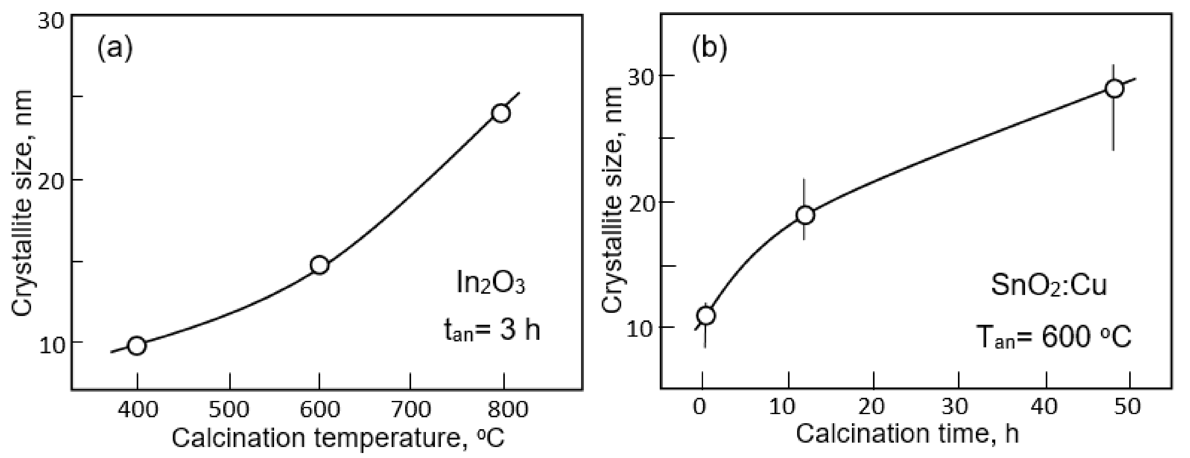
- Park, J.Y.; Asokan, K.; Choi, S.-W.; Kim, S.S. Growth kinetics of nanograins in SnO2 fibers and size dependent sensing properties. Sens. Actuators B Chem. 2011, 152, 254–260. [Google Scholar] [CrossRef]
- Kim, I.-D.; Rothschild, A. Nanostructured metal oxide gas sensors prepared by electrospinning. Polym. Adv. Technol. 2011, 22, 318–325. [Google Scholar] [CrossRef]
- Jiang, C.; Zhang, G.; Wu, Y.; Li, L.; Shi, K. Facile synthesis of SnO2 nanocrystalline tubes by electrospinning and their fast response and high sensitivity to NOx at room temperature. CrystEngComm 2012, 14, 2739–2747. [Google Scholar] [CrossRef]
- Karimi, E.Z.; Esmaeilzadeh, J.; Marzbanrad, E. Electrospun TiO2 nanofibre-based gas sensors fabricated by AC electrophoresis deposition. Bull. Mater. Sci. 2015, 38, 209–214. [Google Scholar] [CrossRef]
- Giancaterini, L.; Emamjomeh, S.M.; De Marcellis, A.; Palange, E.; Resmini, A.; Anselmi-Tamburini, U.; Cantalini, C. The influence of thermal and visible light activation modes on the NO2 response of WO3 nanofibers prepared by electrospinning. Sens. Actuators B Chem. 2016, 229, 387–395. [Google Scholar] [CrossRef]
- Chi, X.; Liu, C.; Liu, L.; Li, Y.; Wang, Z.; Bo, X.; Liu, L.; Su, C. Tungsten trioxide nanotubes with high sensitive and selective properties to acetone. Sens. Actuators B Chem. 2014, 194, 33–37. [Google Scholar] [CrossRef]
- Cho, N.G.; Yang, D.J.; Jin, M.-J.; Kim, H.-G.; Tuller, H.L.; Kim, I.-D. Highly sensitive SnO2 hollow nanofiber-based NO2 gas sensors. Sens. Actuators B Chem. 2011, 160, 1468–1472. [Google Scholar] [CrossRef]
- Liu, Y.; Ding, Y.; Zhang, L.; Gao, P.-X.; Lei, Y. CeO2 nanofibers for in situ O2 and CO sensing in harsh environments. RSC Adv. 2012, 2, 5193–5198. [Google Scholar] [CrossRef]
- Liu, Y.; Ding, Y.; Gao, H.; Zhang, L.; Gao, P.; Li, B.; Lei, Y. La0.67Sr0.33MnO3 nanofibers for in situ, real-time, and stable high temperature oxygen sensing. RSC Adv. 2012, 2, 3872–3877. [Google Scholar] [CrossRef]
- Katoch, A.; Choi, S.-W.; Kim, H.W.; Kim, S.S. Highly sensitive and selective H2 sensing by ZnO nanofibers and the underlying sensing mechanism. J. Hazard. Mater. 2015, 286, 229–235. [Google Scholar] [CrossRef]
- Park, J.-A.; Moon, J.; Lee, S.-J.; Kim, S.H.; Zyung, T.; Chu, H.Y. Structure and CO gas sensing properties of electrospun TiO2 nanofibers. Mater. Lett. 2010, 64, 255–257. [Google Scholar] [CrossRef]
- Park, J.-A.; Moon, J.; Lee, S.-J.; Lim, S.-C.; Zyung, T. Fabrication and characterization of ZnO nanofibers by electrospinning. Curr. Appl. Phys. 2009, 9, S210–S212. [Google Scholar] [CrossRef]
- Lim, S.K.; Hwang, S.-H.; Chang, D.; Kim, S. Preparation of mesoporous In2O3 nanofibers by electrospinning and their application as a CO gas sensor. Sens. Actuators B Chem. 2010, 149, 28–33. [Google Scholar] [CrossRef]
- Wei, S.; Zhao, G.; Du, W.; Tian, Q. Synthesis and excellent acetone sensing properties of porous WO3 nanofibers. Vacuum 2016, 124, 32–39. [Google Scholar] [CrossRef]
- Wei, S.; Zhou, M.; Du, W. Improved acetone sensing properties of ZnO hollow nanofibers by single capillary electrospinning. Sens. Actuators B Chem. 2011, 160, 753–759. [Google Scholar] [CrossRef]
- Liang, X.; Jin, G.; Liu, F.; Zhang, X.; An, S.; Ma, J.; Lu, G. Synthesis of In2O3 hollow nanofibers and their application in highly sensitive detection of acetone. Ceram. Int. 2015, 41, 13780–13787. [Google Scholar] [CrossRef]
- Zheng, W.; Li, Z.; Zhang, H.; Wang, W.; Wang, Y.; Wang, C. Electrospinning route for α-Fe2O3 ceramic nanofibers and their gas sensing properties. Mater. Res. Bull. 2009, 44, 1432–1436. [Google Scholar] [CrossRef]
- Zheng, W.; Lu, X.; Wang, W.; Li, Z.; Zhang, H.; Wang, Y.; Wang, Z.; Wang, C. A highly sensitive and fast-responding sensor based on electrospun In2O3 nanofibers. Sens. Actuators B Chem. 2009, 142, 61–65. [Google Scholar] [CrossRef]
- Liu, O.; Li, W.; Zhu, L.; Li, C.; Qu, F.; Guo, W.; Feng, C.; Ruan, S. Preparation and ethanol sensing properties of In2O3 nanotubes. J. Nanosci. Nanotechnol. 2014, 14, 3653–3657. [Google Scholar] [CrossRef]
- Yoon, J.-W.; Choi, J.-K.; Lee, J.-H. Design of a highly sensitive and selective C2H5OH sensor using p-type Co3O4 nanofibers. Sens. Actuators B Chem. 2012, 161, 570–577. [Google Scholar] [CrossRef]
- Cui, J.; Shi, L.; Xie, T.; Wang, D.; Lin, Y. UV-light illumination room temperature HCHO gas-sensing mechanism of ZnO with different nanostructures. Sens. Actuators B Chem. 2016, 227, 220–226. [Google Scholar] [CrossRef]
- Li, Z.; Fan, Y.; Zhan, J. In2O3 nanofibers and nanoribbons: Preparation by electrospinning and their formaldehyde gas-sensing properties. Eur. J. Inorg. Chem. 2010, 2010, 3348–3353. [Google Scholar] [CrossRef]
- Katoch, A.; Kim, J.H.; Kim, S.S. Significance of the nanograin size on the H2S-sensing ability of CuO-SnO2 composite nanofibers. J. Sens. 2015, 2015, 387641. [Google Scholar] [CrossRef]
- Wang, L.; Cao, J.; Qian, X.; Zhang, H. Facile synthesis and enhanced gas sensing properties of grain size-adjustable In2O3 micro/nanotubes. Mater. Lett. 2016, 171, 30–33. [Google Scholar] [CrossRef]
- Khalil, A.; Kim, J.J.; Tuller, H.L.; Rutledge, G.C.; Hashaikeh, R. Gas sensing behavior of electrospun nickel oxide nanofibers: Effect of morphology and microstructure. Sens. Actuators B Chem. 2016, 227, 54–64. [Google Scholar] [CrossRef]
- Katoch, A.; Abideen, Z.U.; Kim, J.-H.; Kim, S.S. Influence of hollowness variation on the gas-sensing properties of ZnO hollow nanofibers. Sens. Actuators B Chem. 2016, 232, 698–704. [Google Scholar] [CrossRef]
- Cho, S.; Kim, D.-H.; Lee, B.-S.; Jung, J.; Yu, W.-R.; Hong, S.-H.; Lee, S. Ethanol sensors based on ZnO nanotubes with controllable wall thickness via atomic layer deposition, an O2 plasma process and an annealing process. Sens. Actuators B Chem. 2012, 162, 300–306. [Google Scholar] [CrossRef]
- Yu, X.; Song, F.; Zhai, B.; Zheng, C.; Wang, Y. Electrospun ZnO nanotubes and its gas sensing applications. Phys. E Low-Dimens. Syst. Nanostructures 2013, 52, 92–96. [Google Scholar] [CrossRef]
- Cao, J.; Dou, H.; Zhang, H.; Mei, H.; Liu, S.; Fei, T.; Wang, R.; Wang, L.; Zhang, T. Controllable synthesis and HCHO-sensing properties of In2O3 micro/nanotubes with different diameters. Sens. Actuators B Chem. 2014, 198, 180–187. [Google Scholar] [CrossRef]
- Zhang, J.; Choi, S.-W.; Kim, S.S. Micro- and nano-scale hollow TiO2 fibers by coaxial electrospinning: Preparation and gas sensing. J. Solid State Chem. 2011, 184, 3008–3013. [Google Scholar] [CrossRef]
- Fu, J.; Zhang, J.; Peng, Y.; Zhao, C.; He, Y.; Zhang, Z.; Pan, X.; Mellors, N.J.; Xie, E. Wire-in-tube structure fabricated by single capillary electrospinning via nanoscale Kirkendall effect: The case of nickel-zinc ferrite. Nanoscale 2013, 5, 12551–12557. [Google Scholar] [CrossRef]
- Zhang, Z.; Yang, G.; Wei, J.; Bian, H.; Gao, J.; Li, J.; Wang, T. Morphology and magnetic properties of CoFe2O4 nanocables fabricated by electrospinning based on the Kirkendall effect. J. Cryst. Growth 2016, 445, 42–46. [Google Scholar] [CrossRef]
- Ji, W.; Wei, H.; Cui, Y.; Wei, Y.; Bu, J.; Feng, Z.; Wang, P.; Li, H.; Luo, L. Facile synthesis of porous forsterite nanofibres by direct electrospinning method based on the Kirkendall effect. Mater. Lett. 2018, 211, 319–322. [Google Scholar] [CrossRef]
- Kim, W.-S.; Lee, B.-S.; Kim, D.-H.; Kim, H.-C.; Yu, W.-R.; Hong, S.-H. SnO2 nanotubes fabricated using electrospinning and atomic layer deposition and their gas sensing performance. Nanotechnology 2010, 21, 245605. [Google Scholar] [CrossRef]
- Choi, S.-J.; Chattopadhyay, S.; Kim, J.J.; Kim, S.-J.; Tuller, H.L.; Rutledge, G.C.; Kim, I.-D. Coaxial electrospinning of WO3 nanotubes functionalized with bio-inspired Pd catalysts and their superior hydrogen sensing performance. Nanoscale 2016, 8, 9159–9166. [Google Scholar] [CrossRef]
- Chattopadhyay, S.; Saha, J.; De, G. Electrospun anatase TiO2 nanofibers with ordered mesoporosity. J. Mater. Chem. A 2014, 2, 19029–19035. [Google Scholar] [CrossRef]
- Zhao, D.; Huo, Q.; Feng, J.; Chmelka, B.F.; Stucky, S.D. Nonionic triblock and star diblock copolymer and oligomeric surfactant syntheses of highly ordered, hydrothermally stable, mesoporous silica structures. J. Am. Chem. Soc. 1998, 120, 6024–6036. [Google Scholar] [CrossRef]
- Saha, J.; De, G. Highly ordered cubic mesoporous electrospun SiO2 nanofibers. Chem. Commun. 2013, 49, 6322–6324. [Google Scholar] [CrossRef] [PubMed]
- Korotcenkov, G. Gas response control through structural and chemical modification of metal oxides: State of the art and approaches. Sens. Actuators B Chem. 2005, 107, 209–232. [Google Scholar] [CrossRef]
- Korotcenkov, G.; Cho, B.K. Engineering approaches to improvement operating characteristics of conductometric gas sensors. Part 1: Improvement of sensor sensitivity and selectivity. Sens. Actuators B Chem. 2013, 188, 709–728. [Google Scholar] [CrossRef]
- Korotcenkov, G.; Brinzari, V.; Cho, B.K. Conductometric gas sensors based on metal oxide modified with gold nanoparticles: A review. Microchim. Acta 2016, 183, 1033–1054. [Google Scholar] [CrossRef]
- Katoch, A.; Byun, J.-H.; Choi, S.-W.; Kim, S.S. One-pot synthesis of Au-loaded SnO2 nanofibers and their gas sensing properties. Sens. Actuators B Chem. 2014, 202, 38–45. [Google Scholar] [CrossRef]
- Kou, X.; Meng, F.; Chen, K.; Wang, T.; Sun, P.; Liu, F.; Yan, X.; Sun, Y.; Liu, F.; Shimanoe, K.; et al. High-performance acetone gas sensor based on Ru-doped SnO2 nanofibers. Sens. Actuators B Chem. 2020, 320, 128292. [Google Scholar] [CrossRef]
- Jaroenapibal, P.; Boonma, P.; Suksilaporn, N.; Horprathum, M.; Amornkitbamrung, V.; Triroj, N. Improved NO2 sensing performance of electrospun WO3 nanofibers with silver doping. Sens. Actuators B Chem. 2018, 255, 1831–1840. [Google Scholar] [CrossRef]
- Dong, K.-Y.; Choi, J.-K.; Hwang, I.-S.; Lee, J.-W.; Kang, B.H.; Ham, D.-J.; Lee, J.-H.; Ju, B.-K. Enhanced H2S sensing characteristics of Pt doped SnO2 nanofibers sensors with micro heater. Sens. Actuators B Chem. 2011, 157, 154–161. [Google Scholar] [CrossRef]
- Kim, K.-H.; Kim, S.-J.; Cho, H.-J.; Kim, N.-H.; Jang, J.-S.; Choi, S.-J.; Kim, I.-D. WO3 nanofibers functionalized by protein-templated RuO2 nanoparticles as highly sensitive exhaled breath gas sensing layers. Sens. Actuators B Chem. 2017, 241, 1276–1282. [Google Scholar] [CrossRef]
- Cho, H.-J.; Kim, S.-J.; Choi, S.-J.; Jang, J.-S.; Kim, I.-D. Facile synthetic method of catalyst-loaded ZnO nanofibers composite sensor arrays using bio-inspired protein cages for pattern recognition of exhaled breath. Sens. Actuators B Chem. 2017, 243, 166–175. [Google Scholar] [CrossRef]
- Hu, Q.; Huang, B.; Li, Y.; Zhang, S.; Zhang, Y.; Hua, X.; Liu, G.; Li, B.; Zhou, J.; Xie, E.; et al. Methanol gas detection of electrospun CeO2 nanofibers by regulating Ce3+/Ce4+ mole ratio via Pd doping. Sens. Actuators B Chem. 2020, 307, 127638. [Google Scholar] [CrossRef]
- Zheng, W.; Lu, X.; Wang, W.; Li, Z.; Zhang, H.; Wang, Z.; Xu, X.; Li, S.; Wang, C. Assembly of Pt nanoparticles on electrospun In2O3 nanofibers for H2S detection. J. Colloid Interface Sci. 2009, 338, 366–370. [Google Scholar] [CrossRef]
- Wang, S.; Jia, F.; Wang, X.; Hu, L.; Sun, Y.; Yin, G.; Zhou, T.; Feng, Z.; Kumar, P.; Liu, B. Fabrication of ZnO nanoparticles modified by uniformly dispersed Ag nanoparticles: Enhancement of gas sensing performance. ACS Omega 2020, 5, 5209–5218. [Google Scholar] [CrossRef]
- Jang, J.-S.; Choi, S.-J.; Kim, S.-J.; Hakim, M.; Kim, I.-D. Rational design of highly porous SnO2 nanotubes functionalized with biomimetic nanocatalysts for direct observation of simulated diabetes. Adv. Funct. Mater. 2016, 26, 4740–4748. [Google Scholar] [CrossRef]
- Krivetskiy, V.; Ponzoni, A.; Comini, E.; Badalyan, S.; Rumyantseva, M.; Gaskov, A. Selectivity modification of SnO2-based materials for gas sensor arrays. Electroanalysis 2010, 22, 2809–2816. [Google Scholar] [CrossRef]
- Krivetskiy, V.V.; Rumyantseva, M.N.; Gaskov, A.M. Chemical modification of nanocrystalline tin dioxide for selective gas sensors. Russ. Chem. Rev. 2013, 82, 917–941. [Google Scholar] [CrossRef]
- Hubner, M.; Koziej, D.; Grunwaldt, J.-D.; Weimar, U.; Barsan, N. An Au clusters related spill-over sensitization mechanism in SnO2-based gas sensors identified by operando HERFD-XAS, work function changes, DC resistance and catalytic conversion studies. Phys. Chem. Chem. Phys. 2012, 14, 13249–13254. [Google Scholar] [CrossRef]
- Hübner, M.; Bârsan, N.; Weimar, U. Influences of Al, Pd and Pt additives on the conduction mechanism as well as the surface and bulk properties of SnO2 based polycrystalline thick film gas sensors. Sens. Actuators B Chem. 2012, 171, 172–180. [Google Scholar] [CrossRef]
- Korotcenkov, G.; Cho, B.K. Bulk doping influence on the response of conductometric SnO2 gas sensors: Understanding through cathodoluminescence study. Sens. Actuators B Chem. 2014, 196, 80–98. [Google Scholar] [CrossRef]
- Marikutsa, A.; Rumyantseva, M.; Konstantinova, E.; Shatalova, T.; Gaskov, A. Active sites on nanocrystalline tin dioxide surface: Effect of Palladium and Ruthenium oxides clusters. J. Phys. Chem. C 2014, 118, 21541–21549. [Google Scholar] [CrossRef]
- Degler, D.; Rank, R.; Müller, S.; Pereira de Carvalho, H.W.; Grunwaldt, J.D. Gold-loaded tin dioxide gas sensing materials: Mechanistic insights and the role of gold dispersion. ACS Sens. 2016, 1, 1322–1329. [Google Scholar] [CrossRef]
- Degler, D.; Müller, S.A.; Doronkin, D.E.; Wang, D.; Grunwaldt, J.D.; Weimar, U. Platinum loaded tin dioxide: A model system for unravelling the interplay between heterogeneous catalysis and gas sensing. J. Mater. Chem. A 2018, 6, 2034–2046. [Google Scholar] [CrossRef]
- Degler, D.; Weimar, U.; Barsan, N. Current understanding of the fundamental mechanisms of doped and loaded semiconducting metal-oxide-based gas sensing materials. ACS Sens. 2019, 4, 2228–2249. [Google Scholar] [CrossRef]
- Barbosa, M.S.; Suman, P.H.; Kim, J.J.; Tuller, H.L.; Orland, M.O. Investigation of electronic and chemical sensitization effects promoted by Pt and Pd nanoparticles on single-crystalline SnO nanobelt-based gas sensors. Sens. Actuators B Chem. 2019, 301, 127055. [Google Scholar] [CrossRef]
- Tang, W.; Wang, J.; Qiao, Q.; Liu, Z.; Li, X. Mechanism for acetone sensing property of Pd-loaded SnO2 nanofibers prepared by electrospinning: Fermi-level effects. J. Mater. Sci. 2015, 50, 2605–2615. [Google Scholar] [CrossRef]
- Lin, Y.; Wei, W.; Li, Y.; Li, F.; Zhou, J.; Sun, D.; Chen, Y.; Ruan, S. Preparation of Pd nanoparticle-decorated hollow SnO2 nanofibers and their enhanced formaldehyde sensing properties. J. Alloys Compd. 2015, 651, 690–698. [Google Scholar] [CrossRef]
- Wei, S.; Yu, Y.; Zhou, M. CO gas sensing of Pd-doped ZnO nanofibers synthesized by electrospinning method. Mater. Lett. 2010, 64, 2284–2286. [Google Scholar] [CrossRef]
- Moon, J.; Park, J.-A.; Lee, S.-J.; Zyung, T.; Kim, I.-D. Pd-doped TiO2 nanofiber networks for gas sensor applications Pd-doped TiO2 nanofiber networks for gas sensor applications. Sens. Actuators B Chem. 2010, 149, 301–305. [Google Scholar] [CrossRef]
- Kim, N.-H.; Choi, S.-J.; Yang, D.-J.; Bae, J.; Park, J.; Kim, I.-D. Highly sensitive and selective hydrogen sulfide and toluene sensors using Pd functionalized WO3 nanofibers for potential diagnosis of halitosis and lung cancer. Sens. Actuators B Chem. 2014, 193, 574–581. [Google Scholar] [CrossRef]
- Choi, S.-J.; Lee, I.; Jang, B.-H.; Youn, D.-Y.; Ryu, W.-H.; Park, C.O.; Kim, I.-D. Selective diagnosis of diabetes using Pt-functionalized WO3 hemitube networks as a sensing layer of acetone in exhaled breath. Anal. Chem. 2013, 85, 1792–1796. [Google Scholar] [CrossRef]
- Guo, L.; Xie, N.; Wang, C.; Kou, X.; Ding, M.; Zhang, H.; Sun, Y.; Song, H.; Wang, Y.; Lu, G. Enhanced hydrogen sulfide sensing properties of Pt-functionalized α-Fe2O3 nanowires prepared by one-step electrospinning. Sens. Actuators B Chem. 2018, 255, 1015–1023. [Google Scholar] [CrossRef]
- Cho, N.G.; Woo, H.-S.; Lee, J.-H.; Kim, I.-D. Thin-walled NiO tubes functionalized with catalytic Pt for highly selective C2H5OH sensors using electrospun fibers as a sacrificial template. Chem. Commun. 2011, 47, 11300–11302. [Google Scholar] [CrossRef]
- Kim, J.H.; Abideen, Z.U.; Zheng, Y.; Kim, S.S. Improvement of toluene-sensing performance of SnO2 nanofibers by Pt functionalization. Sensors 2016, 16, 1857. [Google Scholar] [CrossRef] [PubMed]
- Xu, X.; Chen, Y.; Zhang, G.; Ma, S.; Lu, Y.; Bian, H.; Chen, Q. Highly sensitive VOCs-acetone sensor based on Ag-decorated SnO2 hollow nanofibers. J. Alloys Compd. 2017, 703, 572–579. [Google Scholar] [CrossRef]
- Ma, S.; Jia, J.; Tian, Y.; Cao, L.; Shi, S.; Li, X.; Wang, X. Improved H2S sensing properties of Ag/TiO2 nanofibers. Ceram. Intern. 2016, 42, 2041–2044. [Google Scholar] [CrossRef]
- Wang, J.; Zou, B.; Ruan, S.; Zhao, J.; Chen, Q.; Wu, F. HCHO sensing properties of Ag-doped In2O3 nanofibers synthesized by electrospinning. Mater. Lett. 2009, 63, 1750–1753. [Google Scholar] [CrossRef]
- Kim, J.H.; Zheng, Y.; Mirzaei, A.; Kim, S.S. Excellent carbon monoxide sensing performance of Au-decorated SnO2 nanofibers. Korean J. Mater. Res. 2016, 26, 741–750. [Google Scholar] [CrossRef]
- Xu, X.; Fan, H.; Liu, Y.; Wang, L.; Zhang, T. Au-loaded In2O3 nanofibers-based ethanol micro gas sensor with low power consumption. Sens. Actuators B Chem. 2011, 160, 713–719. [Google Scholar] [CrossRef]
- Yang, X.; Salles, V.; Kaneti, Y.V.; Liu, M.; Maillard, M.; Journet, C.; Jiang, X.; Brioude, A. Fabrication of highly sensitive gas sensor based on Au functionalized WO3 composite nanofibers by electrospinning. Sens. Actuators B Chem. 2015, 220, 1112–1119. [Google Scholar] [CrossRef]
- Matsushima, S.; Teraoka, Y.; Miura, N.; Yamazoe, N. Electronic interaction between metal additives and tin dioxide in tin dioxide-based gas sensors. Jpn. J. Appl. Phys. 1988, 51, 1798–1803. [Google Scholar] [CrossRef]
- Lee, Y.C.; Huang, H.; Tan, O.K.; Tse, M.S. Semiconductor gas sensor based on Pd-doped SnO2 nanorod thin films. Sens. Actuators B Chem. 2008, 132, 239–242. [Google Scholar] [CrossRef]
- Fryberger, T.D.; Semancik, S. Conductance response of Pd/SnO2 model gas sensors to H2 and O2. Sens. Actuators B Chem. 1990, 2, 305–319. [Google Scholar] [CrossRef]
- Zhao, C.; Bai, J.; Huang, B.; Wang, Y.; Zhou, J.; Xie, E. Grain refining effect of calcium dopants on gas-sensing properties of electrospun α-Fe2O3 nanotubes. Sens. Actuators B Chem. 2016, 231, 552–560. [Google Scholar] [CrossRef]
- Shan, H.; Liu, C.; Liu, L.; Li, S.; Wang, L.; Zhang, X.; Bo, X.; Chi, X. Highly sensitive acetone sensors based on La-doped-Fe2O3 nanotubes. Sens. Actuators B Chem. 2013, 184, 243–247. [Google Scholar] [CrossRef]
- Mohanapriya, P.; Segawa, H.; Watanabe, K.; Watanabe, K.; Samitsu, S.; Natarajan, T.; Jaya, N.V.; Ohashi, N. Enhanced ethanol-gas sensing performance of Ce-doped SnO2 hollow nanofibers prepared by electrospinning. Sens. Actuators B Chem. 2013, 188, 872–878. [Google Scholar] [CrossRef]
- Cheng, Y.; Wang, Y.; Zhang, J.; Li, H.; Liu, L.; Li, Y.; Du, L.; Duan, H. A comparison of Eu-doped α-Fe2O3 nanotubes and nanowires for acetone sensing. Nano 2017, 12, 1750138. [Google Scholar] [CrossRef]
- Li, W.; Ma, S.; Li, Y.; Li, X.; Wang, C.; Yang, X.; Cheng, L.; Mao, Y.; Luo, J.; Gengzang, D.; et al. Preparation of Pr-doped SnO2 hollow nanofibers by electrospinning method and their gas sensing properties. J. Alloys Compd. 2014, 605, 80–88. [Google Scholar] [CrossRef]
- Liu, Y.-J.; Zhang, H.-D.; Zhang, J.; Li, S.; Zhang, J.-C.; Zhu, J.-W. Effects of Ce doping and humidity on UV sensing properties of electrospun ZnO nanofibers. J. Appl. Phys. 2017, 122, 105102. [Google Scholar] [CrossRef]
- Cheng, L.; Ma, S.; Li, X.; Luo, J.; Li, W.; Li, F.; Mao, Y.; Wang, T.; Li, Y. Highly sensitive acetone sensors based on Y-doped SnO2 prismatic hollow nanofibers synthesized by electrospinning. Sens. Actuators B Chem. 2014, 200, 181–190. [Google Scholar] [CrossRef]
- Cheng, J.P.; Wang, B.B.; Zhao, M.G.; Liu, F.; Zhang, X.B. Nickel-doped tin oxide hollow nanofibers prepared by electrospinning for acetone sensing. Sens. Actuators B Chem. 2014, 190, 78–85. [Google Scholar] [CrossRef]
- Liu, L.; Li, S.; Zhuang, J.; Wang, L.; Zhang, J.; Li, H.; Liu, Z.; Han, Y.; Jiang, X.; Zhang, P. Improved selective acetone sensing properties of Co-doped ZnO nanofibers by electrospinning. Sens. Actuators B Chem. 2011, 155, 782–788. [Google Scholar] [CrossRef]
- Liu, L.; Zhang, T.; Wang, L.; Li, S. Improved ethanol sensing properties of Cu-doped SnO2 nanofibers. Mater. Lett. 2009, 63, 2041–2043. [Google Scholar] [CrossRef]
- Wang, Z.; Liu, L. Synthesis and ethanol sensing properties of Fe-doped SnO2 nanofibers. Mater. Lett. 2009, 63, 917–919. [Google Scholar] [CrossRef]
- Liu, Y.; Sun, X.; Li, B.; Lei, Y. Tunable p-n transition behaviour of a p-La0.67Sr0.33MnO3/n-CeO2 nanofibers heterojunction for the development of selective high temperature propane sensors. J. Mater. Chem. A 2014, 2, 11651–11659. [Google Scholar] [CrossRef]
- Bai, X.; Ji, H.; Gao, P.; Zhang, Y.; Sun, X. Morphology, phase structure and acetone sensitive properties of copper-doped tungsten oxide sensors. Sens. Actuators B Chem. 2014, 193, 100–106. [Google Scholar] [CrossRef]
- Qin, W.; Xu, L.; Song, J.; Xing, R.; Song, H. Highly enhanced gas sensing properties of porous SnO2-CeO2 composite nanofibers prepared by electrospinning. Sens. Actuators B Chem. 2013, 185, 231–237. [Google Scholar] [CrossRef]
- Gas’kov, A.; Rumyantseva, M. Metal oxide nanocomposites: Synthesis and characterization in relation with gas sensing phenomena. In Sensors for Environment, Health and Security; Baraton, M.I., Ed.; Springer Science + Business Media B.V.: Dordrecht, The Netherlands, 2009; pp. 3–29. [Google Scholar]
- Korotcenkov, G.; Boris, I.; Brinzari, V.; Han, S.H.; Cho, B.K. The role of doping effect on the response of SnO2-based thin film gas sensors: Analysis based on the results obtained for Co-doped SnO2 films deposited by spray pyrolysis. Sens. Actuators B Chem. 2013, 182, 112–124. [Google Scholar] [CrossRef]
- Korotcenkov, G.; Boris, I.; Cho, B.K. SnO2:Cu films doped during spray pyrolysis deposition: The reasons of the gas sensing properties change. Mater. Chem. Phys. 2013, 142, 124–131. [Google Scholar] [CrossRef]
- Rumyantseva, M.N.; Safonova, O.V.; Boulova, M.N.; Ryabova, L.I.; Gas’kov, A.M. Dopants in nanocrystalline tin dioxide. Russ. Chem. Bull. Intern. Ed. 2003, 52, 1217–1238. [Google Scholar] [CrossRef]
- Gerasimov, G.N.; Gromov, V.F.; Belysheva, T.V.; Ikim, M.; Trakhtenberg, L.I. Effect of the composition and structure of metal oxide nanocomposites on the sensor process when detecting reducing gases. Russ. J. Phys. Chem. 2017, 91, 1609–1620. [Google Scholar] [CrossRef]
- Wang, C.-N.; Li, Y.-L.; Gong, F.-L.; Zhang, Y.-H.; Fang, S.-M.; Zhang, H.-L. Advances in doped ZnO nanostructures for gas sensor. Chem. Rec. 2020, 20, 1553–1567. [Google Scholar] [CrossRef] [PubMed]
- Xu, L.; Xing, R.; Song, J.; Xu, W.; Song, H. ZnO-SnO2 nanotubes surface engineered by Ag nanoparticles: Synthesis, characterization, and highly enhanced HCHO gas sensing properties. J. Mater. Chem. C 2013, 1, 2174–2182. [Google Scholar] [CrossRef]
- Wan, G.X.; Ma, S.Y.; Sun, X.W.; Sun, A.M.; Li, X.B.; Luo, J.; Li, W.Q.; Wang, C.Y. Synthesis of wrinkled and porous ZnO-SnO2 hollow nanofibers and their gas sensing properties. Mater. Lett. 2015, 145, 48–51. [Google Scholar] [CrossRef]
- Katoch, A.; Kim, J.-H.; Kim, S.S. CuO/SnO2 Mixed Nanofibers for H2S Detection. J. Nanosci. Nanotechnol. 2015, 15, 8637–8641. [Google Scholar] [CrossRef]
- Deng, J.; Wang, L.; Lou, Z.; Zhang, T. Design of CuO–TiO2 heterostructure nanofibers and their sensing performance. J. Mater. Chem. A 2014, 2, 9030–9034. [Google Scholar] [CrossRef]
- Lu, Z.; Zhou, Q.; Wang, C.; Wei, Z.; Xu, L.; Gui, Y. Electrospun ZnO-SnO2 composite nanofibers and enhanced sensing properties to SF6 decomposition byproduct H2S. Front. Chem. 2018, 6, 540. [Google Scholar] [CrossRef]
- Feng, C.; Li, X.; Ma, J.; Sun, Y.; Wang, C.; Sun, P.; Zheng, J.; Lu, G. Facile synthesis and gas sensing properties of In2O3-WO3 heterojunction nanofibers. Sens. Actuators B Chem. 2015, 209, 622–629. [Google Scholar] [CrossRef]
- Hsu, K.-C.; Fang, T.-H.; Tang, I.-T.; Hsiao, Y.-J.; Chen, C.-Y. Mechanism and characteristics of Au-functionalized SnO2/In2O3 nanofibers for highly sensitive CO detection. J. Alloys Compd. 2020, 822, 153475. [Google Scholar] [CrossRef]
- Gao, J.; Wang, L.; Kan, K.; Xu, S.; Jing, L.; Liu, S.; Shen, P.; Li, L.; Shi, K. One-step synthesis of mesoporous Al2O3-In2O3 nanofibres with remarkable gas-sensing performance to NOx at room temperature. J. Mater. Chem. A 2014, 2, 949–956. [Google Scholar] [CrossRef]
- Cao, J.; Wang, Z.Y.; Wang, R.; Liu, S.; Fei, T.; Wang, L.J. Synthesis of core-shell α-Fe2O3@NiO nanofibers with hollow structures and their enhanced HCHO sensing properties. J. Mater. Chem. A 2015, 3, 5635–5641. [Google Scholar] [CrossRef]
- Cao, J.; Wang, Z.; Wang, R.; Liu, S.; Fei, T.; Wang, L.; Zhang, T. Core-shell Co3O4/α-Fe2O3 heterostructure nanofibers with enhanced gas sensing properties. RSC Adv. 2015, 5, 36340–36346. [Google Scholar] [CrossRef]
- Liu, J.; Li, X.; Chen, X.; Niu, H.; Han, X.; Zhang, T.; Lin, H.; Qu, F. Synthesis of SnO2/In2O3 hetero-nanotubes by coaxial-electrospinning method for enhanced formaldehyde response. New J. Chem. 2016, 40, 1756–1764. [Google Scholar] [CrossRef]
- Deng, J.; Yu, B.; Lou, Z.; Wang, L.; Wang, R.; Zhang, T. Facile synthesis and enhanced ethanol sensing properties of the brush-like ZnO-TiO2 heterojunctions nanofibers. Sens. Actuators B Chem. 2013, 184, 21–26. [Google Scholar] [CrossRef]
- Wan, K.; Wang, D.; Wang, F.; Li, H.; Xu, J.; Wang, X.; Yang, J. Hierarchical In2O3@SnO2 core−shell nanofiber for high efficiency formaldehyde detection. ACS Appl. Mater. Interface 2019, 11, 45214–45225. [Google Scholar] [CrossRef]
- Lou, Z.; Li, F.; Deng, J.; Wang, L.; Zhang, T. Branch-like hierarchical heterostructure (α-Fe2O3/TiO2): A novel sensing material for trimethylamine gas sensors. ACS Appl. Mater. Interfaces 2013, 5, 12310–12316. [Google Scholar] [CrossRef] [PubMed]
- Qi, Q.; Wang, P.P.; Zhao, J.; Feng, L.L.; Zhou, L.J.; Xuan, R.F. SnO2 nanoparticle-coated In2O3 nanofibers with improved NH3 sensing properties. Sens. Actuators B Chem. 2014, 194, 440–446. [Google Scholar] [CrossRef]
- Zhang, N.; Li, F.; Yin, Y.; Han, J.; Li, X.; Liu, C.; Zhou, J.; Wen, S.; Adimi, S.; Chen, Y.; et al. Gas sensor based on TiO2 nanofibers decorated with monodispersed WO3 nanocubes for fast and selective xylene detection. Mater. Sci. Eng. B 2021, 263, 114901. [Google Scholar] [CrossRef]
- Frank, G.; Brock, L.; Bausen, H.D. The solubilities of Sn in In2O3 and of In in SnO2 crystals grown from Sn-In melts. J. Cryst. Growth 1976, 36, 179–180. [Google Scholar] [CrossRef]
- Enoki, H.; Echigoya, J.; Suto, H. The intermediate compound in the In2O3-SnO2 system. J. Mater. Sci. 1991, 26, 4110–4115. [Google Scholar] [CrossRef]
- Fitzgerald, C.B.; Venkatesan, M.; Douvalis, A.P.; Huber, S.; Coey, J.M.D. SnO2 doped with Mn, Fe or Co: Room temperature dilute magnetic semiconductors. J. Appl. Phys. 2004, 95, 7390. [Google Scholar] [CrossRef]
- Music, S. X-ray diffraction and Mössbauer spectra of the system Fe2O3-SnO2. J. Mater. Sci. Lett. 1991, 10, 197–200. [Google Scholar] [CrossRef]
- Lu, B.; Wang, C.; Zhang, Y. Electron beam induced crystallization in Fe-doped SnO2 nanoparticles. Appl. Phys. Lett. 1997, 70, 717–719. [Google Scholar] [CrossRef]
- Punnoose, A.; Hays, J.; Thurber, A.; Engelhard, M.H.; Kukkadapu, R.K.; Wang, C.; Shutthnandan, V.; Thevuthasan, S. Development of high-temperature ferromagnetism in SnO2 and paramagnetism in SnO by Fe doping. Phys. Rev. B 2005, 72, 054402. [Google Scholar] [CrossRef]
- Pandya, D.K.; Gopinadhan, K.; Kashyap, S.C. On the role of impurities on ferromagnetism in nanocrystalline SnO2:Ni thick films. Synth. React. Inorg. Met.-Org. Nano-Met. Chem. 2008, 38, 162–167. [Google Scholar]
- Aragon, F.H.; Coaquira, J.A.H.; Hidalgo, P.; da Silva, S.W.; Brito, S.L.M.; Gouvea, D.; Morais, P.C. Evidences of the evolution from solid solution to surface segregation in Ni-doped SnO2 nanoparticles using Raman spectroscopy. J. Raman Spectrosc. 2001, 42, 1081–1086. [Google Scholar] [CrossRef]
- Gouvea, D.; Varela, J.A.; Santilli, C.V.; Longp, E. Effect of Niobia on the sintering of SnO2. In Science of Sintering; Uskovic, D.P., Palmour, H., III, Spriggs, R.M., Eds.; Plenum Press: New York, NY, USA, 1989; pp. 529–536. [Google Scholar]
- Kim, B.; Jung, J.; Lee, J.; Kim, J. Precipitate concentration of Co2SnO4 in CoO-doped SnO2 ceramics at different oxygen chemical potentials. Solid State Ion. 2001, 144, 321–327. [Google Scholar] [CrossRef]
- Tena, M.A.; Meseguer, S.; Gargori, C.; Fores, A.; Badenes, J.A.; Monros, G. Study of Cr-SnO2 ceramic pigment and of Ti/Sn ratio on formation and coloration of these materials. J. Eur. Ceram. Soc. 2007, 27, 215–221. [Google Scholar] [CrossRef]
- Li, J.; Liu, S.; Pan, W. Co-doped tin oxide thin films by spin coating. Key Eng. Mater. 2008, 368–372, 524–525. [Google Scholar] [CrossRef]
- Cabezas, M.D.; Lamas, D.G.; Baby, R.E.; Cabanillas, E.; Walsöe de Reca, N.E. Nanostructured thick film sensors for CO(g) based on Al doped SnO2. In Anales de la Asociación Química Argentina; Asociación Química Argentina: Buenos Aires, Argentina, 2005; Volume 93, pp. 69–74. [Google Scholar]
- Tricoli, A.; Graf, M.; Pratsinis, S.E. Optimal doping for enhanced SnO2 sensitivity and thermal stability. Adv. Funct. Mater. 2008, 18, 1969–1976. [Google Scholar] [CrossRef]
- Giaquinta, D.M.; Davis, W.M.; Zur Loye, H.C. Structure of indium iron oxide. Acta Crystallogr. Sect. C Cryst. Struct. Commun. C 1994, 50, 5–7. [Google Scholar] [CrossRef]
- Yoo, Y.K.; Xue, Q.; Lee, H.-C.; Cheng, S.; Xiang, X.-D.; Dionne, G.F.; Xu, S.; He, J.; Chu, Y.S.; Preite, S.D.; et al. Bulk synthesis and high-temperature ferromagnetism of (In1−xFex)2O3−6 with Cu co-doping. Appl. Phys. Lett. 2005, 86, 042506. [Google Scholar] [CrossRef]
- Ratko, A.; Babushkin, O.; Baran, A.; Baran, S. Sorption and gas sensitive properties of In2O3 based ceramics doped with Ga2O3. J. Eur. Ceram. Soc. 1998, 18, 2227–2232. [Google Scholar] [CrossRef]
- Ohya, Y.; Ito, T.; Kaneko, M.; Ban, T.; Takahashi, Y. Solid solubility of SnO2 in In2O3. J. Ceram. Soc. Jpn. 2000, 108, 803–806. [Google Scholar] [CrossRef]
- Gonzalez, G.B.; Mason, T.O.; Okasinski, J.S.; Buslaps, T.; Honkimaki, V. Determination of the solubility of tin in indium oxide using in situ and ex situ X-ray diffraction. J. Am. Ceram. Soc. 2012, 95, 1809–1815. [Google Scholar] [CrossRef]
- Parthiban, S.; Gokulakrishnan, V.; Ramamurthi, K.; Elangovan, E.; Martins, R.; Fortunato, E.; Ganesan, R. High near-infrared transparent molybdenum-doped indium oxide thin films for nanocrystalline silicon solar cell applications. Sol. Energy Mater. Sol. Cells 2009, 93, 92–97. [Google Scholar] [CrossRef]
- Kaleemulla, S.; Rao, N.M.; Joshi, M.G.; Reddy, A.S.; Uthanna, S.; Reddy, P.S. Electrical and optical properties of In2O3:Mo thin films prepared at various Mo-doping levels. J. Alloys Compd. 2010, 504, 351–356. [Google Scholar] [CrossRef]
- Sunde, T.O.L.; Lindgren, M.; Mason, T.O.; Einarsrud, M.-A.; Grande, T. Solid solubility of rare earth elements (Nd, Eu, Tb) in In2−xSnxO3—effect on electrical conductivity and optical properties. Dalton Trans. 2014, 43, 9620–9632. [Google Scholar] [CrossRef]
- Berardan, A.; Guilmeau, E.; Maignan, A.; Raveau, B. In2O3:Ge: A promising n-type thermoelectric oxide composite. Solid State Commun. 2008, 146, 97–101. [Google Scholar] [CrossRef]
- Godzhieva, O.V.; Porotnikov, N.V.; Pikhidchuk, V.P. Physical-chemical study of triple oxides Formed in In2O3-CaO-CuO System. Zhur. Neorg. Khim. 1992, 37, 1184–1188. [Google Scholar]
- Horyn, R.; Bukowska, E.; Sikora, A. Studies of BaO-In2O3-CuO ternary system. Part I: Phase equilibria in the isothermal cross-section of 930 oC. J. Alloys Compd. 2000, 305, 103–108. [Google Scholar] [CrossRef]
- Mandal, S.K.; Das, A.K.; Nath, T.K.; Karmakar, D. Temperature dependence of solubility limits of transition metals (Co, Mn, Fe, and Ni) in ZnO nanoparticles. Appl. Phys. Lett. 2006, 89, 144105. [Google Scholar] [CrossRef]
- Morkoc, H.; Ozgur, U. Zinc Oxide; Wiley VCH: Weinheim, Germany, 2009. [Google Scholar]
- Jin, Z.; Fukumura, T.; Kawasaki, M.; Ando, K.; Saito, H.; Sekiguchi, T.; Yoo, Y.Z.; Murakami, M.; Matsumoto, Y.; Hasegawa, T.; et al. High throughput fabrication of transition-metal-doped epitaxial ZnO thin films: A series of oxide-diluted magnetic semiconductors and their properties. Appl. Phys. Lett. 2001, 78, 3824–3826. [Google Scholar] [CrossRef]
- Chahmat, N.; Haddad, A.; Ain-Souya, A.; Ganfoudi, R.; Attaf, N.; Salah Aida, M.; Ghers, M. Effect of Sn doping on the properties of ZnO thin films prepared by spray pyrolysis. J. Mod. Phys. 2012, 3, 1781–1785. [Google Scholar] [CrossRef]
- Serier, H.; Gaudon, M.; Manetrier, M. Al-doped ZnO powdered materials. Phys. Rev. B 2000, 61, 15019–15027. [Google Scholar]
- Yoon, M.H.; Lee, S.H.; Park, H.L.; Kim, H.K.; Jang, M.S. Solid solubility limits of Ga and Al in ZnO. J. Mater. Sci. Lett. 2002, 21, 1703–1704. [Google Scholar] [CrossRef]
- Park, D.H.; Son, K.Y.; Lee, J.H.; Kim, J.J.; Lee, J.S. Effect of ZnO addition in In2O3 ceramics: Defect chemistry and sintering behavior. Solid State Ion. 2004, 172, 431–434. [Google Scholar] [CrossRef]
- Park, J.Y.; Choi, S.W.; Lee, J.W.; Lee, C.; Kim, S.S. Synthesis and gas sensing properties of TiO2-ZnO core shell nanofibers. J. Am. Ceram. Soc. 2009, 92, 2551–2554. [Google Scholar] [CrossRef]
- Wu, H.; Kan, K.; Wang, L.; Zhang, G.; Yang, Y.; Li, H. Electrospinning of mesoporous p-type In2O3/TiO2 composite nanofibers for enhancing NOx gas sensing properties at room temperature. CrystEngComm 2014, 16, 9116–9124. [Google Scholar] [CrossRef]
- Liang, X.; Kim, T.H.; Yoon, J.W.; Kwak, C.H.; Lee, J.H. Ultrasensitive and ultraselective detection of H2S using electrospun CuO-loaded In2O3 nanofiber sensors assisted by pulse heating. Sens. Actuators B Chem. 2015, 209, 934–942. [Google Scholar] [CrossRef]
- Katoch, A.; Choi, S.W.; Kim, J.H.; Lee, J.H.; Lee, J.S.; Kim, S.S. Importance of the nanograin size on the H2S sensing properties of ZnO-CuO composite nanofibers. Sens. Actuators B Chem. 2015, 214, 111–116. [Google Scholar] [CrossRef]
- Katoch, A.; Choi, S.W.; Sun, G.J.; Kim, H.W.; Kim, S.S. Mechanism and prominent enhancement of sensing ability to reducing gases in p/n core-shell nanofiber. Nanotechnology 2014, 25, 175501–175508. [Google Scholar] [CrossRef]
- Lee, J.H.; Katoch, A.; Choi, S.W.; Kim, J.H.; Kim, H.W.; Kim, S.S. Extraordinary improvement of gas-sensing performances in SnO2 nanofibers due to creation of local p-n heterojunctions by loading reduced graphene oxide nanosheets. ACS Appl. Mater. Interfaces 2015, 7, 3101–3109. [Google Scholar] [CrossRef] [PubMed]
- Katoch, A.; Kim, J.H.; Kim, S.S. TiO2/ZnO inner/outer double-layer hollow fibers for improved detection of reducing gases. ACS Appl. Mater. Interfaces 2014, 6, 21494–21499. [Google Scholar] [CrossRef] [PubMed]
- Katoch, A.; Choi, S.W.; Sun, G.J.; Kim, S.S. An approach to detecting a reducing gas by radial modulation of electron-depleted shells in core-shell nanofibers. J. Mater. Chem. A 2013, 1, 13588–13596. [Google Scholar] [CrossRef]
- Yang, A.; Tao, X.; Wang, R.; Lee, S.; Surya, C. Room temperature gas sensing properties of SnO2/multiwall carbon-nanotube composite nanofibers. Appl. Phys. Lett. 2007, 91, 133110–133113. [Google Scholar] [CrossRef]
- Wang, Z.L.; Li, Z.; Sun, J.; Zhang, H.; Wang, W.; Zheng, W.; Wang, C. Improved hydrogen monitoring properties based on p-NiO/n-SnO2 heterojunction composite nanofibers. J. Phys. Chem. C 2010, 114, 6100–6105. [Google Scholar] [CrossRef]
- Feng, C.; Li, W.; Li, C.; Zhu, L.; Zhang, H.; Zhang, Y.; Ruan, S.; Chen, W.; Yu, L. Highly efficient rapid ethanol sensing based on In2-xNixO3 nanofibers. Sens. Actuators B Chem. 2012, 166, 83–88. [Google Scholar] [CrossRef]
- Zhang, X.J.; Qiao, G.J. High performance ethanol sensing films fabricated from ZnO and In2O3 nanofibers with a double-layer structure. Appl. Surf. Sci. 2012, 258, 6643–6647. [Google Scholar] [CrossRef]
- Yan, S.; Wu, Q.S. Micropored Sn-SnO2/carbon heterostructure nanofibers and their highly sensitive and selective C2H5OH gas sensing performance. Sens. Actuators B Chem. 2014, 205, 329–337. [Google Scholar] [CrossRef]
- Tang, W.; Wang, J.; Yao, P.J.; Li, X.G. Hollow hierarchical SnO2-ZnO composite nanofibers with heterostructure based on electrospinning method for detecting methanol. Sens. Actuators B Chem. 2014, 192, 543–549. [Google Scholar] [CrossRef]
- Wang, B.; Fu, X.X.; Liu, F.; Shi, S.L.; Cheng, J.P.; Zhang, X.B. Fabrication and gas sensing properties of hollow core-shell SnO2/α-Fe2O3 heterogeneous structures. J. Alloys Compd. 2014, 587, 82–89. [Google Scholar] [CrossRef]
- Zheng, Y.; Wang, J.; Yao, P. Formaldehyde sensing properties of electrospun NiO-doped SnO2 nanofibers. Sens. Actuators B Chem. 2011, 156, 723–730. [Google Scholar] [CrossRef]
- Du, H.; Wang, J.; Su, M.; Yao, P.; Zheng, Y.; Yu, N. Formaldehyde gas sensor based on SnO2/In2O3 hetero-nanofibers by a modified double jets electrospinning process. Sens. Actuators B Chem. 2012, 166, 746–752. [Google Scholar] [CrossRef]
- Ho, T.A.; Jun, T.S.; Kim, Y.S. Material and NH3-sensing properties of polypyrrole-coated tungsten oxide nanofibers. Sens. Actuators B Chem. 2013, 185, 523–529. [Google Scholar] [CrossRef]
- Li, Y.H.; Gong, J.; He, G.H.; Deng, Y.L. Fabrication of polyaniline/titanium dioxide composite nanofibers for gas sensing application. Mater. Chem. Phys. 2011, 129, 477–482. [Google Scholar] [CrossRef]
- Liu, L.; Zhang, Y.; Wang, G.G.; Li, S.C.; Wang, L.Y.; Han, Y. High toluene sensing properties of NiO-SnO2 composite nanofiber sensors operating at 330 °C. Sens. Actuators B Chem. 2011, 160, 448–454. [Google Scholar] [CrossRef]
- Qi, Q.; Zou, Y.C.; Fan, M.-H.; Liu, Y.P.; Gao, S.; Wang, P.P. Trimethylamine sensors with enhanced anti humidity ability fabricated from La0.7Sr0.3FeO3 coated In2O3-SnO2 composite nanofibers. Sens. Actuators B Chem. 2014, 203, 111–117. [Google Scholar] [CrossRef]
- Li, C.; Feng, C.H.; Qu, F.D.; Liu, J.; Zhu, L.H.; Lin, Y. Electrospun nanofibers of p-type NiO/n-type ZnO heterojunction with different NiO content and its influence on trimethylamine sensing properties. Sens. Actuators B Chem. 2015, 207, 90–96. [Google Scholar] [CrossRef]
- Lee, S.; Kim, I.D.; Lee, J.H. Selective and sensitive detection of trimethylamine using ZnO-In2O3 composite nanofibers. Sens. Actuators B Chem. 2013, 181, 463–470. [Google Scholar] [CrossRef]
- Miller, D.R.; Akbar, S.A.; Morris, P.A. Nanoscale metal oxide-based heterojunctions for gas sensing: A review. Sens. Actuators B Chem. 2014, 204, 250–272. [Google Scholar] [CrossRef]
- Li, T.; Zeng, W.; Wang, Z. Quasi-one-dimensional metal-oxide-based heterostructural gas-sensing materials: A review. Sens. Actuators B Chem. 2015, 221, 1570–1585. [Google Scholar] [CrossRef]
- Gerasimov, G.N.; Gromov, V.F.; Ilegbusi, O.J.; Trakhtenberg, L.I. The mechanisms of sensory phenomena in binary metal-oxide nanocomposites. Sens. Actuators B Chem. 2017, 240, 613–624. [Google Scholar] [CrossRef]
- Zappa, D.; Galstyan, V.; Kaur, N.; Arachchige, H.M.M.; Sisman, O.; Comini, E. Metal oxide -based heterostructures for gas sensors—A review. Anal. Chim. Acta 2018, 1039, 1–23. [Google Scholar] [CrossRef] [PubMed]
- Bag, A.; Lee, N.-E. Gas sensing with heterostructures based on two-dimensional nanostructured materials: A review. J. Mater. Chem. C 2019, 7, 13367. [Google Scholar] [CrossRef]
- Jian, Y.; Hu, W.; Zhao, Z.; Cheng, P.; Haick, H.; Yao, M.; Wu, W. Gas sensors based on chemi-resistive hybrid functional nanomaterials. Nano-Micro Lett. 2020, 12, 71. [Google Scholar] [CrossRef]
- Park, S.; Ko, H.; Kim, S.; Lee, C. Role of the interfaces in multiple networked one-dimensional core-shell nanostructured gas sensors. ACS Appl. Mater. Interfaces 2014, 6, 9595–60023. [Google Scholar] [CrossRef]
- Redel, E.; Arsenault, E.; O’Brien, P.G.; Kherani, N.P.; Ozin, G.A. Growth of metal nanocrystals on nanostructured metal oxides—Dramatic effect of antimony doping. Chem. Mater. 2011, 23, 1353–1355. [Google Scholar] [CrossRef]
- Walker, J.M.; Akbar, S.A.; Morris, P.A. Synergistic effects in gas sensing semiconducting oxide nanohetero structures: A review. Sens. Actuators B Chem. 2019, 286, 624–640. [Google Scholar] [CrossRef]
- Du, H.; Wang, H.; Yao, P.; Wang, J.; Sun, Y. In2O3 nanofibers surface modified by low-temperature plasma and their gas sensing properties. Mater. Chem. Phys. 2018, 215, 316–326. [Google Scholar] [CrossRef]
- Kim, J.-H.; Mirzaei, A.; Kim, H.W.; Wue, P.; Kim, S.S. Design of supersensitive and selective ZnO-nanofiber-based sensors for H2 gas sensing by electron-beam irradiation. Sens. Actuators B Chem. 2019, 293, 210–223. [Google Scholar] [CrossRef]
- Chen, K.; Pi, K.; Zhang, D. Ultraviolet irradiation enhanced formaldehyde-sensing performance based on SnO2@TiO2 nanofiber heteroarchitectures. J. Phys. D Appl. Phys. 2020, 53, 125301. [Google Scholar] [CrossRef]
- Li, J.; Gu, D.; Yang, Y.; Du, H.; Li, X. UV light activated SnO2/ZnO nanofibers for gas sensing at room temperature. Front. Mater. 2019, 6, 158. [Google Scholar] [CrossRef]
- Cho, M.; Park, I. Recent trends of light-enhanced metal oxide gas sensors: Review. J. Sens. Sci. Technol. 2016, 25, 103–109. [Google Scholar] [CrossRef]
- Espid, E.; Taghipour, F. UV-LED photo-activated chemical gas sensors: A review. Crit. Rev. Solid State 2017, 42, 416–432. [Google Scholar] [CrossRef]
- Xu, F.; Ho, H.-P. Light-activated metal oxide gas sensors: A review. Micromachines 2017, 8, 333. [Google Scholar] [CrossRef]
- Kumar, R.; Liu, X.; Zhang, J.; Kumar, M. Room-temperature gas sensors under photoactivation: From metal oxides to 2D materials. Nano-Micro Lett. 2020, 12, 164. [Google Scholar] [CrossRef]
- Wang, J.; Shen, H.; Xia, Y.; Komarneni, S. Light-activated room-temperature gas sensors based on metal oxide nanostructures: A review on recent advances. Ceram Intern. 2021, 47, 7353–7368. [Google Scholar] [CrossRef]
- Suh, J.M.; Eom, T.H.; Cho, S.H.; Kim, T.; Jang, H.W. Light-activated gas sensing: Prospective of integration with micro-LEDs and plasmonic nanoparticles. Mater. Adv. 2021, 2, 827–844. [Google Scholar] [CrossRef]
- Prades, J.D.; Jimenes-Diaz, R.; Hernandez-Ramirez, F.; Fernandez-Romero, L.; Andreu, T.; Cirera, A.; Romano-Rodriguez, A.; Cornet, A.; Morante, J.R.; Barth, S.; et al. Toward a systematic understanding of photodetectors based on individual metal oxide nanowires. J. Phys. Chem. C 2008, 112, 14639–14644. [Google Scholar] [CrossRef]
- Comini, E.; Faglia, G.; Sberveglieri, G. Electrical-based gas sensing. In Solid State Gas Sensing; Comini, E., Faglia, G., Sberveglieri, G., Eds.; Springer: New York, NY, USA, 2009; pp. 47–107. [Google Scholar]
- Prades, J.D.; Jemenes-Diaz, R.; Manzanares, M.; Hernandez-Ramirez, F.; Cirera, A.; Romano-Rodriguez, A.; Marthur, S.; Morante, J.R. A model for the response towards oxidizing gases of photoactivated sensors based on individual SnO2 nanowires. Phys. Chem. Chem. Phys. 2009, 11, 10881–10889. [Google Scholar] [CrossRef]
- Liu, C.; Shan, H.; Liu, L.; Li, S.; Li, H. High sensing properties of Ce-doped α-Fe2O3 nanotubes to acetone. Ceram. Intern. 2014, 40, 2395–2399. [Google Scholar] [CrossRef]
- Seitz, C.; Werner, S.; Marschall, R.; Smarsly, B.M. Electrospun CuO nanofibre assemblies for H2S sensing. Zeitschrift Phys. Chem. 2019, 233, 105–116. [Google Scholar] [CrossRef]
- Kapse, V.D.; Ghosh, S.A.; Chaudhari, G.N.; Raghuwanshi, F.C. Nanocrystalline In2O3-based H2S sensors operable at low temperatures. Talanta 2008, 76, 610–616. [Google Scholar] [CrossRef]
- Huang, Z.M.; Zhang, Y.Z.; Kotaki, M.; Ramakrishna, S. A review on polymer nanofibers by electrospinning and their applications in nanocomposites. Compos. Sci. Technol. 2003, 63, 2223–2253. [Google Scholar] [CrossRef]
- Mondal, K.; Sharma, A. Recent advances in electrospun metal-oxide nanofiber based interfaces for electrochemical biosensing. RSC Adv. 2016, 6, 94595–94616. [Google Scholar] [CrossRef]
- Lee, J.A.; Krogman, K.C.; Ma, M.; Hill, R.M.; Hammond, P.T.; Rutledge, G.C. Highly reactive multilayer-assembled TiO2 coating on electrospun polymer nanofibers. Adv. Mater. 2009, 21, 1252–1256. [Google Scholar] [CrossRef]
- Sahner, K.; Tuller, H.L. Novel deposition techniques for metal oxide: Prospects for gas sensing. J. Electroceram. 2010, 24, 177–199. [Google Scholar] [CrossRef]
- Meng, Y.; Liu, G.; Liu, A.; Guo, Z.; Sun, W.; Shan, F. Photochemical activation of electrospun In2O3 nanofibers for high performance electronic devices. ACS Appl. Mater. Interfaces 2017, 9, 10805–10812. [Google Scholar] [CrossRef]
- Kim, I.-D.; Rothschild, A.; Lee, B.H.; Kim, D.Y.; Jo, S.M.; Tuller, H.L. Ultrasensitive chemiresistors based on electrospun TiO2 nanofibers. Nano Lett. 2006, 6, 2009–2013. [Google Scholar] [CrossRef] [PubMed]
- Cui, Y.; Meng, Y.; Wang, Z.; Wang, C.; Liu, G.; Martins, R.; Fortunato, E.; Shan, F. High performance electronic devices based on nanofibers via crosslinking welding process. Nanoscale 2018, 10, 19427–19434. [Google Scholar] [CrossRef] [PubMed]
- Zhang, H.; Meng, Y.; Song, L.; Luo, L.; Qin, Y.; Han, N.; Yang, Z.; Liu, L.; Ho, J.C.; Wang, F. High-performance enhancement-mode thin-film transistors based on Mg-doped In2O3 nanofiber networks. Nano Res. 2018, 11, 1227–1237. [Google Scholar] [CrossRef]
- Persano, L.; Camposeo, A.; Tekmen, C.; Pisignano, D. Industrial upscaling of electrospinning and applications of polymer nanofibers: A review. Macromol. Mater. Eng. 2013, 298, 504–520. [Google Scholar] [CrossRef]
- Xue, J.; Wu, T.; Dai, Y.; Xia, Y. Electrospinning and electrospun nanofibers: Methods, materials, and applications. Chem. Rev. 2019, 119, 5298–5415. [Google Scholar] [CrossRef] [PubMed]
- Thompson, C.J.; Chase, G.G.; Yarin, A.L.; Reneker, D.H. Effects of parameters on nanofiber diameter determined from electrospinning model. Polymer 2007, 48, 6913–6922. [Google Scholar] [CrossRef]
- Demir, M.M.; Yilgor, I.; Yilgor, E.; Erman, B. Electrospinning of polyurethane fibers. Polymer 2002, 43, 3303–3309. [Google Scholar] [CrossRef]
- Bisht, G.S.; Canton, G.; Mirsepassi, A.; Kulinsky, L.; Oh, S.; Dunn-Rankin, D.; Madou, M.J. Controlled continuous patterning of polymeric nanofibers on three-dimensional substrates using low-voltage near-field electrospinning. Nano Lett. 2011, 11, 1831–1837. [Google Scholar] [CrossRef]
- Huang, Y.; Bu, N.; Duan, Y.; Pan, Y.; Liu, H.; Yin, Z.; Xiong, Y. Electrohydrodynamic direct-writing. Nanoscale 2013, 5, 12007–12017. [Google Scholar] [CrossRef] [PubMed]
- Lei, T.P.; Lu, X.Z.; Yang, F. Fabrication of various micro/nano structures by modified near-field electrospinning. AIP Adv. 2015, 5, 041301. [Google Scholar] [CrossRef]
- Fuh, Y.K.; Hsu, H.S. Fabrication of monolithic polymer nanofluidic channels via near-field electrospun nanofibers as sacrificial templates. J. Micro/Nanolithograph MEMS MOEMS 2011, 10, 043004. [Google Scholar] [CrossRef]
- Wang, X.; Zheng, G.; Xu, L.; Cheng, W.; Xu, B.; Huang, Y.; Sun, D. Fabrication of nanochannels via near-field electrospinning. Appl. Phys. A 2012, 108, 825–828. [Google Scholar] [CrossRef]
- Chang, J.; Liu, Y.M.; Heo, K.; Lee, B.Y.; Lee, S.W.; Lin, L.W. Direct-write complementary graphene field effect transistors and junctions via near-field electrospinning. Small 2014, 10, 1920–1925. [Google Scholar] [CrossRef] [PubMed]
- Luo, K.S.; Liu, T.Y.; Zang, X.; Wen, Z.; Lin, L. Direct-write, self-aligned electrospinning on paper for controllable fabrication of three-dimensional structures. ACS Appl. Mater. Interfaces 2015, 7, 27765–27770. [Google Scholar] [CrossRef]
- Kim, J.; Maeng, B.; Park, J. Characterization of 3D electrospinning on inkjet printed conductive pattern on paper. Micro Nano Syst. Lett. 2018, 6, 12. [Google Scholar] [CrossRef]
- Park, Y.-S.; Kim, J.; Oh, J.M.; Park, S.; Cho, S.; Ko, H.; Cho, Y.-K. Near-field electrospinning for three-dimensional stacked nanoarchitectures with high aspect ratios. Nano Lett. 2020, 20, 441–448. [Google Scholar] [CrossRef]
- Brown, T.D.; Dalton, P.D.; Hutmacher, D.W. Direct writing by way of melt electrospinning. Adv. Mater. 2011, 23, 5651–5657. [Google Scholar] [CrossRef] [PubMed]
- Carlberg, B.; Wang, T.; Liu, J. Direct photolithographic patterning of electrospun films for defined nanofibrillar microarchitectures. Langmuir 2010, 26, 2235–2239. [Google Scholar] [CrossRef]
- Sharma, C.S.; Sharma, A.; Madou, M. Multiscale carbon structures fabricated by direct micropatterning of electrospun mats of SU-8 photoresist nanofibers. Langmuir 2010, 26, 2218–2222. [Google Scholar] [CrossRef] [PubMed]
- Jia, C.; Yu, D.; Lamarre, M.; Leopold, P.L.; Teng, Y.D.; Wang, H. Patterned electrospun nanofiber matrices via localized dissolution: Potential for guided tissue formation. Adv. Mater. 2014, 26, 8192–8197. [Google Scholar] [CrossRef] [PubMed]
- Jun, I.; Chung, Y.-W.; Heo, Y.-H.; Han, H.-S.; Park, J.; Jeong, H.; Lee, H.; Lee, Y.B.; Kim, Y.-C.; Seok, H.-K. Creating hierarchical topographies on fibrous platforms using femtosecond laser ablation for directing myoblasts behavior. ACS Appl. Mater. Interfaces 2016, 8, 3407–3417. [Google Scholar] [CrossRef]
- Wang, S.-X.; Yap, C.C.; He, J.; Chen, C.; Wong, S.Y.; Li, X. Electrospinning: A facile technique for fabricating functional nanofibers for environmental applications. Nanotechnol. Rev. 2016, 5, 51–73. [Google Scholar] [CrossRef]
- Jiang, G.; Qin, X. An improved free surface electrospinning for high throughput manufacturing of core–shell nanofibers. Mater. Lett. 2014, 128, 259–262. [Google Scholar] [CrossRef]
- Aliheidari, N.; Aliahmad, N.; Agarwal, M.; Dalir, H. Electrospun nanofibers for label-free sensor applications. Sensors 2019, 19, 3587. [Google Scholar] [CrossRef] [PubMed]
- Kang, K.; Yang, D.; Park, J.; Kim, S.; Cho, I.; Yang, H.-H.; Cho, M.; Mousavi, S.; Choi, K.H.; Park, I. Micropatterning of metal oxide nanofibers by electrohydrodynamic (EHD) printing towards highly integrated and multiplexed gas sensor applications. Sens. Actuators B Chem. 2017, 250, 574–583. [Google Scholar] [CrossRef]
- Yan, S.; Zan, G.; Wu, Q. An ultrahigh-sensitivity and selective sensing material for ethanol: α-/γ-Fe2O3 mixed-phase mesoporous nanofibers. Nano Res. 2015, 8, 3673–3686. [Google Scholar] [CrossRef]
- Hoa, N.D.; Duy, N.V.; El-Safty, S.A.; Hieu, N.V. Meso-/nanoporous semiconducting metal oxides for gas sensor applications. J. Nanomater. 2015, 2015, 972025. [Google Scholar] [CrossRef]
- Li, Z.; Li, H.; Wu, Z.; Wang, M.; Luo, J.; Torun, H.; Hu, P.A.; Yang, C.; Grundmann, M.; Liu, X.; et al. Advances in designs and mechanisms of semiconducting metal oxide nanostructures for high-precision gas sensors operated at room temperature. Mater. Horiz. 2019, 6, 470–506. [Google Scholar] [CrossRef]
- Mirzaei, A.; Kim, H.W.; Kim, S.S.; Neri, G. Nanostructured semiconducting metal oxide gas sensors for acetaldehyde detection. Chemosensors 2019, 7, 56. [Google Scholar] [CrossRef]
- Han, D.; Steckl, A.J. Coaxial electrospinning formation of complex polymer fibers and their applications. ChemPlusChem 2019, 84, 1453–1497. [Google Scholar] [CrossRef] [PubMed]
- Sill, T.J.; von Recum, H.A. Electrospinning: Applications in drug delivery and tissue engineering. Biomaterials 2008, 29, 1989–2006. [Google Scholar] [CrossRef]
- Qu, H.; Wei, S.; Guo, Z. Coaxial electrospun nanostructures and their applications. J. Mater. Chem. A 2013, 1, 11513–11528. [Google Scholar] [CrossRef]


| Sample | Fiber Diameter, nm | Crystallite Size, nm | Surface Area, m2/g | Response |
|---|---|---|---|---|
| SnO2 | ~234 | 41 | 16.7 | ~20 |
| SnO2:Ce | ~127 | 27 | 35 | ~260 |
| Additive | Effect | Nature |
|---|---|---|
| Al2O3; SiO2 | Increases sensor response; improves thermal stability | Decrease in crystallite size; decrease in the area of intergrain contacts; increase in porosity |
| Ag (Ag2O); Cu (Cu2O) | Increases response to H2S, SO2 | Two-phase system; phase transformations during gas detection |
| Fe (Fe2O3) | Increases response to alcohols | Change in oxidation state |
| Ga(Ga2O3); Zn(ZnO) | Increases sensor response | Decrease in crystallite size; increase in porosity |
| P, B | Improves selectivity | Creation of new phase |
| Se | Increases sensor response | Increase in porosity |
| Ca; K; Rb; Mg | Increases sensor response; improves thermal stability | Decrease in crystallite size |
| La; Ba; Y; Ce | Improves thermal stability; increases sensor response | Stabilization of crystallite size (creation of new phases); decrease in crystallite size |
| Transition MOXs: Co; Mn; Sr; Ni | Increases sensor response; improves selectivity | Catalytic effect; change in electron concentration; change in A/D parameters; change in crystallite size |
| Sample | Fiber Diameter, nm | Crystallite Size, nm | Surface Area, m2/g | Toper, °C | S (100 ppm) | τres, s |
|---|---|---|---|---|---|---|
| In2O3 | ~100 | 35 | 18.2 | 275 | ~7 | 23 |
| In2O3-O2 | ~170 | 23 | 32.5 | 275 | ~20 | 27 |
Publisher’s Note: MDPI stays neutral with regard to jurisdictional claims in published maps and institutional affiliations. |
© 2021 by the author. Licensee MDPI, Basel, Switzerland. This article is an open access article distributed under the terms and conditions of the Creative Commons Attribution (CC BY) license (https://creativecommons.org/licenses/by/4.0/).
Share and Cite
Korotcenkov, G. Electrospun Metal Oxide Nanofibers and Their Conductometric Gas Sensor Application. Part 2: Gas Sensors and Their Advantages and Limitations. Nanomaterials 2021, 11, 1555. https://doi.org/10.3390/nano11061555
Korotcenkov G. Electrospun Metal Oxide Nanofibers and Their Conductometric Gas Sensor Application. Part 2: Gas Sensors and Their Advantages and Limitations. Nanomaterials. 2021; 11(6):1555. https://doi.org/10.3390/nano11061555
Chicago/Turabian StyleKorotcenkov, Ghenadii. 2021. "Electrospun Metal Oxide Nanofibers and Their Conductometric Gas Sensor Application. Part 2: Gas Sensors and Their Advantages and Limitations" Nanomaterials 11, no. 6: 1555. https://doi.org/10.3390/nano11061555
APA StyleKorotcenkov, G. (2021). Electrospun Metal Oxide Nanofibers and Their Conductometric Gas Sensor Application. Part 2: Gas Sensors and Their Advantages and Limitations. Nanomaterials, 11(6), 1555. https://doi.org/10.3390/nano11061555