Article

Removal of Impurities from Shungite Via a Combination of Physical and Chemical Treatments

1
College of Resources, Environment and Materials, Guangxi University, Nanning 530004, China
2
Department of Systems Engineering, Graduate School of Engineering, The University of Tokyo, Tokyo 113-8656, Japan
*
Authors to whom correspondence should be addressed.
Minerals 2021, 11(3), 245; https://doi.org/10.3390/min11030245
Submission received: 3 February 2021 / Revised: 18 February 2021 / Accepted: 22 February 2021 / Published: 26 February 2021

Abstract

:
This study investigated the removal of sulfur and iron from shungite rocks through different methods after fine grinding: flotation, magnetic separation, microwave treatment, and chemical leaching. In this work, first, a mineralogical study of shungite was conducted. The carbon, silica, iron, and sulfur compositions in the as-received shungite were 45.4%, 38.3%, 4.6%, and 2.4%, respectively. In flotation, a sulfur grade of 1.4% was obtained. In the wet high-gradient magnetic separation at a magnetic flux density of 1 tesla, the iron and sulfur grades in the nonmagnetic fraction were 2.8% and 1.9%, respectively. Furthermore, the sulfur reduced to 0.2% by the 9 min microwave irradiation. In addition, chemical leaching using chelating reagents and inorganic acids was utilized to remove iron and sulfur. Nitrilotriacetic acid (NTA) could reduce the iron and sulfur grades to 2.0% and 0.9%, respectively. For leaching using reverse aqua regia, the iron and sulfur grades were reduced to 0.9% and 0.23%, respectively. For leaching using a 6N HCl with H2O2 aqueous solution, the iron and sulfur grades were reduced to 0.8% and 0.34%, respectively. Overall, chemical leaching using HCl with H2O2 was the most effective for iron and sulfur removal from shungite.

Graphical Abstract

1. Introduction

Deposits of shungite rocks are produced in the Karelia region of Russia. Shungite is composed of a carbon-and-silica mixture, and it looks like low-crystalline graphite. The main shungite deposit in the world is a 1000 m sedimentary-volcanic succession developed over an area of 9000 km2, with an estimated total carbon reserve exceeding 2 × 10¹⁰ tons [1]. It is a carbon-rich rock produced by the metamorphism of sedimented carbon-rich materials in the Precambrian period. Shungite is characterized by porosity, stiffness, high electrical conductivity, and the tendency to produce SiC when subject to heating. Shungite has a wide range of carbon content, from 10 to 98 wt%. The physical properties of shungite [2]; structural information, obtained via X-ray diffraction (XRD) and scanning electron microscopy (SEM) studies [3]; properties of polylactide/shungite composites [4]; and fullerene content [5] have been reported. Moreover, some applications of shungite have been studied, including its uses as a rubber filler, an adsorbent material for water treatment, a component of composite materials [5], mineral and polymer binders [6], a material for electromagnetic-radiation shielding screens [7], carbonaceous photocatalytic materials [8], and anode materials of Li-ion battery electrodes [9]. The removal of impurities from shungite is essential for its utilization; however, although the amount of shungite resources is large, only a few papers have reported the physical treatment methods of shungite, such as mineral processing and chemical treatment. In the current study, the removal of iron and sulfur impurities through several methods, including flotation, magnetic separation, heat treatment, and chemical leaching, was investigated.

2. Materials and Methods
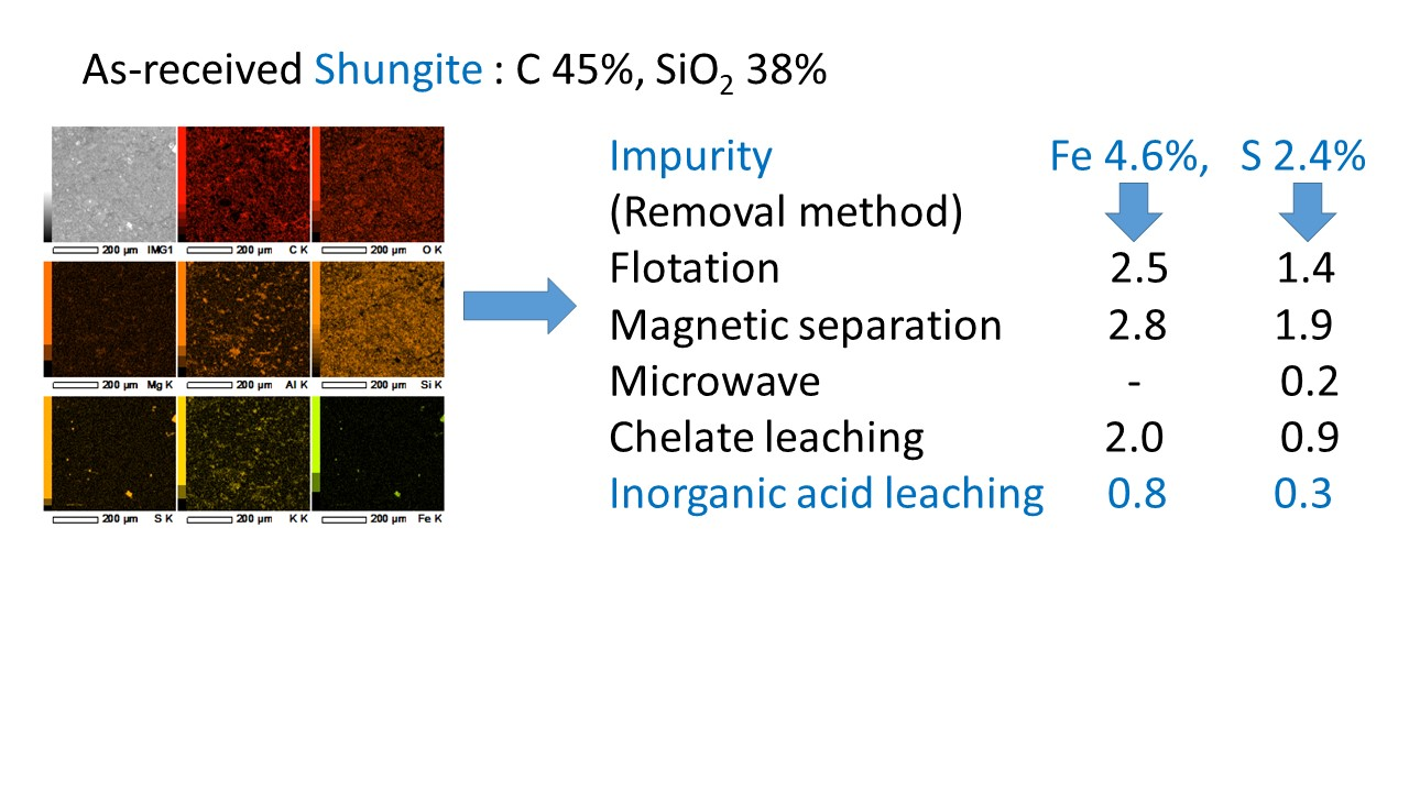
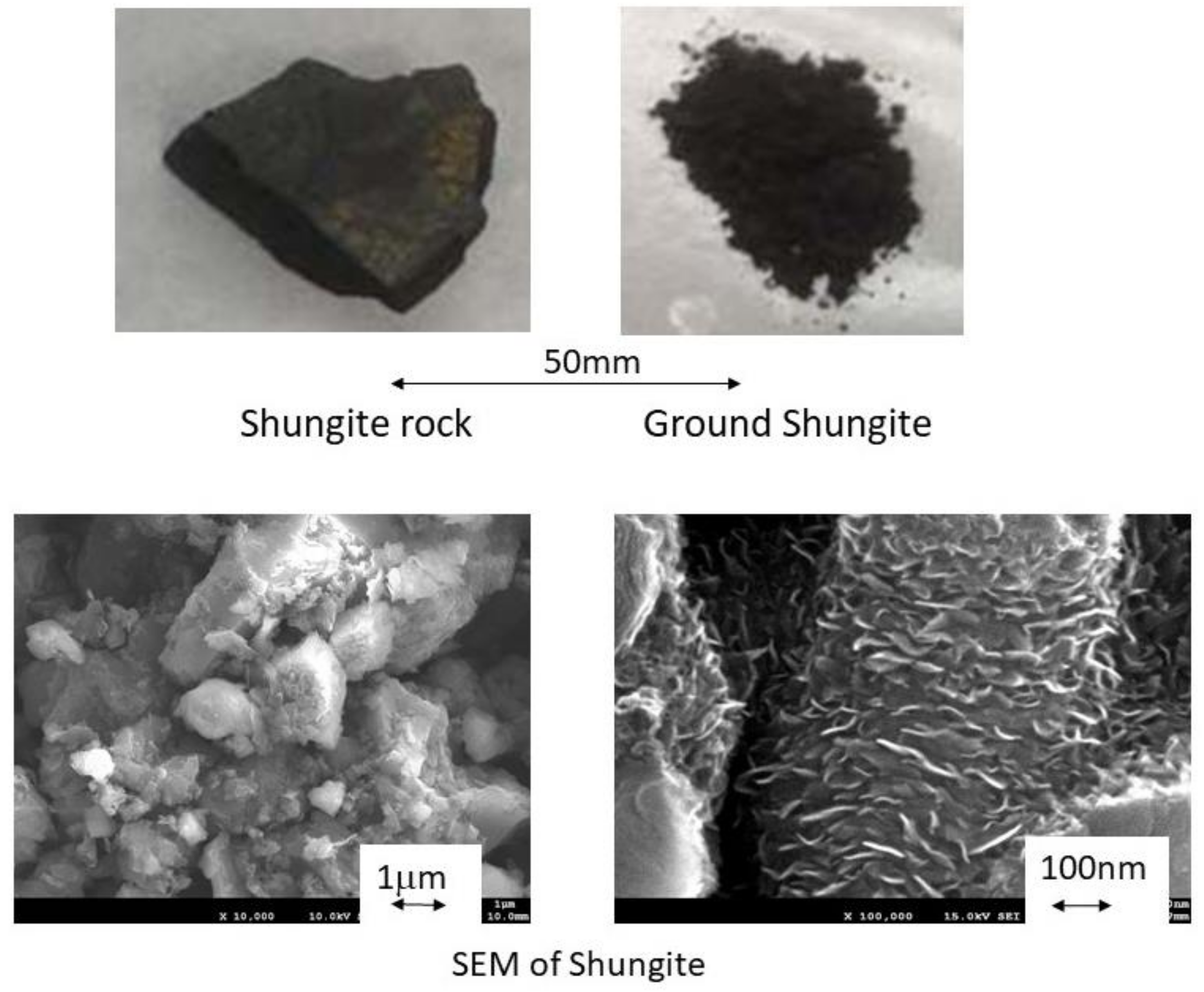
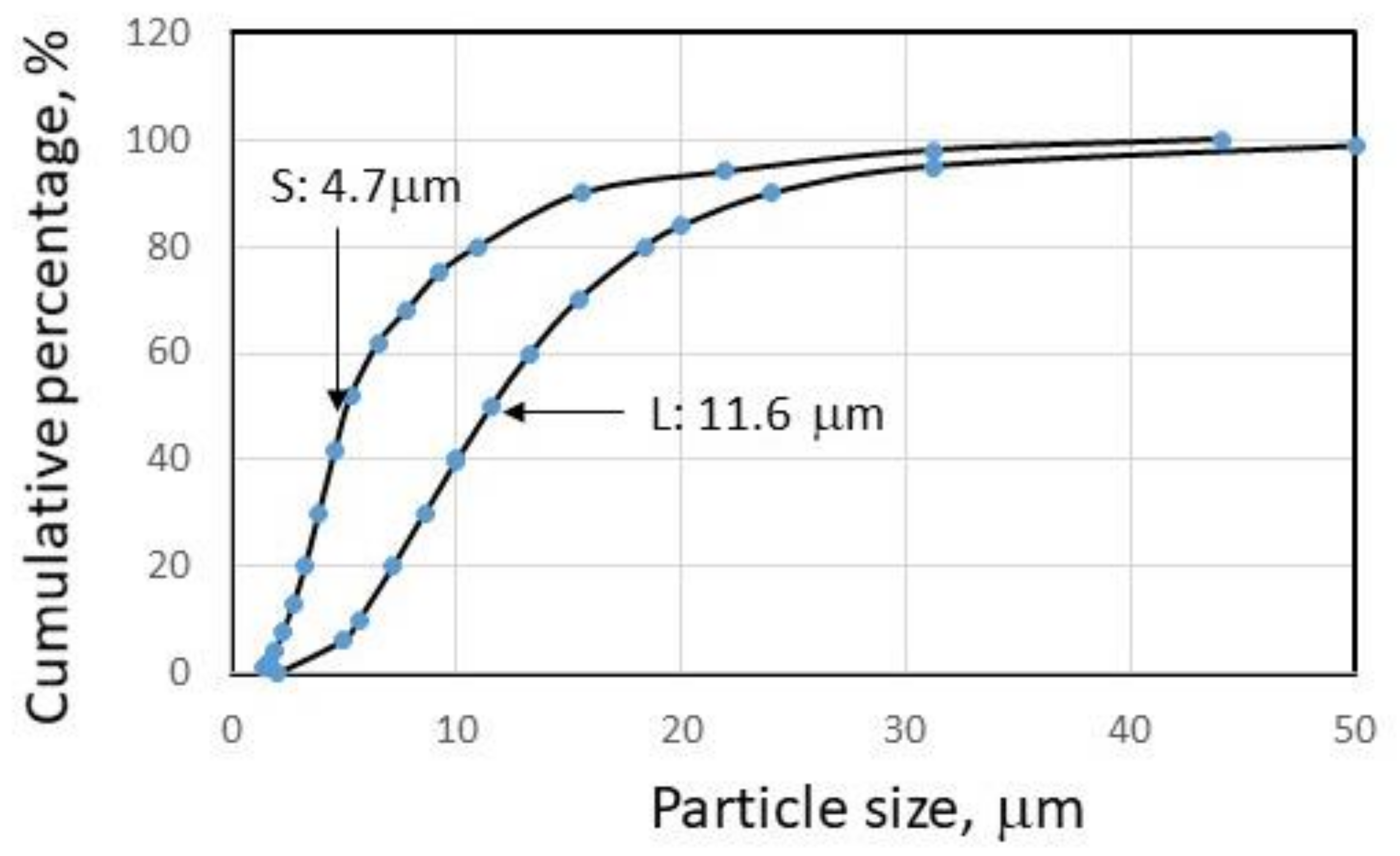
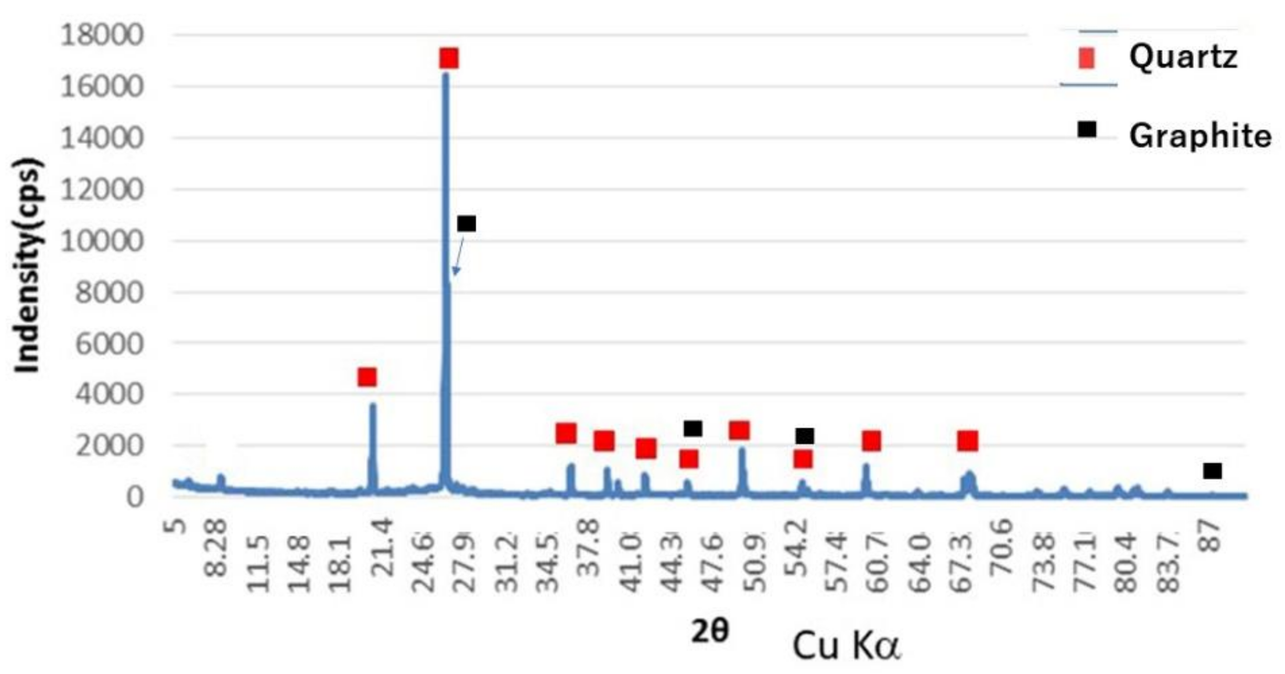
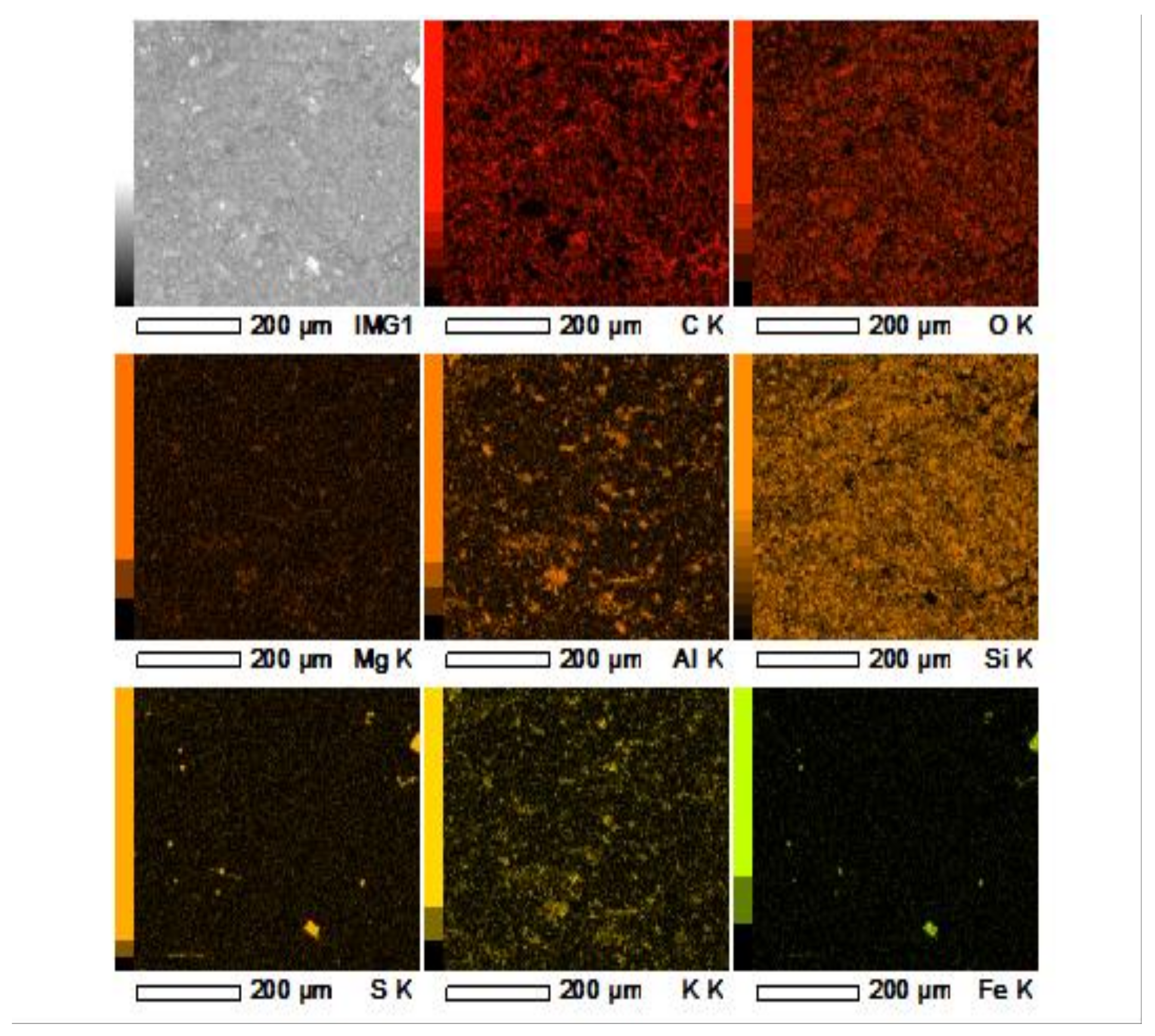
2.1. Materials

Photographs of the as-received shungite sample obtained from the Karelia region are displayed in Figure 1. The Mohs hardness of shungite is similar to that of quartz (i.e., about 7), and the density is around 2000 kg/m3. In this study, the shungite was ground using a ball mill and cutter mill. A scanning electron microscope (JEOL JSM-7001FA SEM) was used to observe the shapes of particles and composition (Figure 1). In this experiment, two ground shungite samples with different mean particle sizes were prepared to investigate impurity removal (Figure 2). Shungite’s structure is very complicated, with a fiber and grain mixture as shown in Figure 1. Therefore, fine- and coarse-ground shungite particle samples were prepared to compare impurity removal in this experiment. As shungite is a hard mineral, with a Mohs hardness of ~7, a long time (10 h) was required to reduce the size to 4.7 μm mean diameter (median diameter D50) through ball-mill wet grinding. The economical crushing of shungite is limited to several μm in size. If dry grinding is performed, dust explosion may occur at a certain carbon powder concentration. The mean diameters (median diameter D50) for coarse and fine particles were 11.6 μm and 4.7 μm, respectively. The liberation degree of small-size particles is usually larger than that of coarse-size particles. In magnetic separation and chemical treatment, the coarse particles (11.6 μm mean diameter) were mainly used for impurity removal for the economical point of preventing long grinding times. The XRD result (Rigaku Co. SmartLab) of the shungite powder is displayed in Figure 3. The quartz and graphite marks are indicated in Figure 3. Crystalline silica peaks were clearly observed, and most graphite peaks overlapped with silica peaks; however, the graphite peaks were observed [10]. In addition, carbon peaks in shungite have been reported by another article [11].
The elemental composition of the as-received shungite is presented in Table 1. Furthermore, chemical analysis and X-ray fluorescence (XRF, Rigaku Co., Supermini) results were used to calculate the compositions. Carbon and silica, which were the main shungite components, accounted for 45.4% and 38.3%, respectively. Regarding the impurity contents, iron and sulfur accounted for 4.6% and 2.4%, respectively, and other elements, including K, Na, Mg, Ca, Al2O3, TiO2, and a small amount of metals such as Zn, Cu, Pb, Mn, and Ni were observed.
To investigate the impurity distribution, the elemental maps of polished shungite coated with gold were measured in a high vacuum via scanning electron microscopy and energy-dispersive X-ray spectroscopy (Figure 4). The C, Si, and O elements were distributed in almost all areas. For the fine structure, it was difficult to separate carbon and SiO2. The Al and K plots were similar, indicating that the shungite contained feldspar and clay mineral impurities. It has also been reported that shungite contains microcrystalline mica and albite [12]. Moreover, given that S and Fe appeared on the same plots, iron sulfides, such as FeS2, existed in the shungite. From EDS spot analysis of the Fe and S ratio in minerals, most of the composition was pyrite. Fe is assumed to exist mainly as pyrite and a small amount of oxide. In this experiment, the removal of iron and sulfur was investigated.
Furthermore, the shungite was analyzed via thermogravimetry/differential thermal analysis (TG-DTA) under atmospheric air conditions, and the result is shown in Figure 5. The moisture content in Table 1 was about 1% by weight loss. The peak at around 500 °C indicates sulfur evaporation. It has been reported that the thermal decomposition of coal-derived pyrite, which starts at approximately 400 °C, is complete at 600 °C [13].
At temperatures of 500 °C to 850 °C, the carbon changed to CO2, and weight loss was observed.
Additionally, the exothermic peak from 500 to 700 °C might be caused by silicon carbide production because silicon carbide was produced after heating shungite to 1000 °C by microwave irradiation which was described in session 3.3.

2.2. Experimental Method for Impurity Removal in Shungite
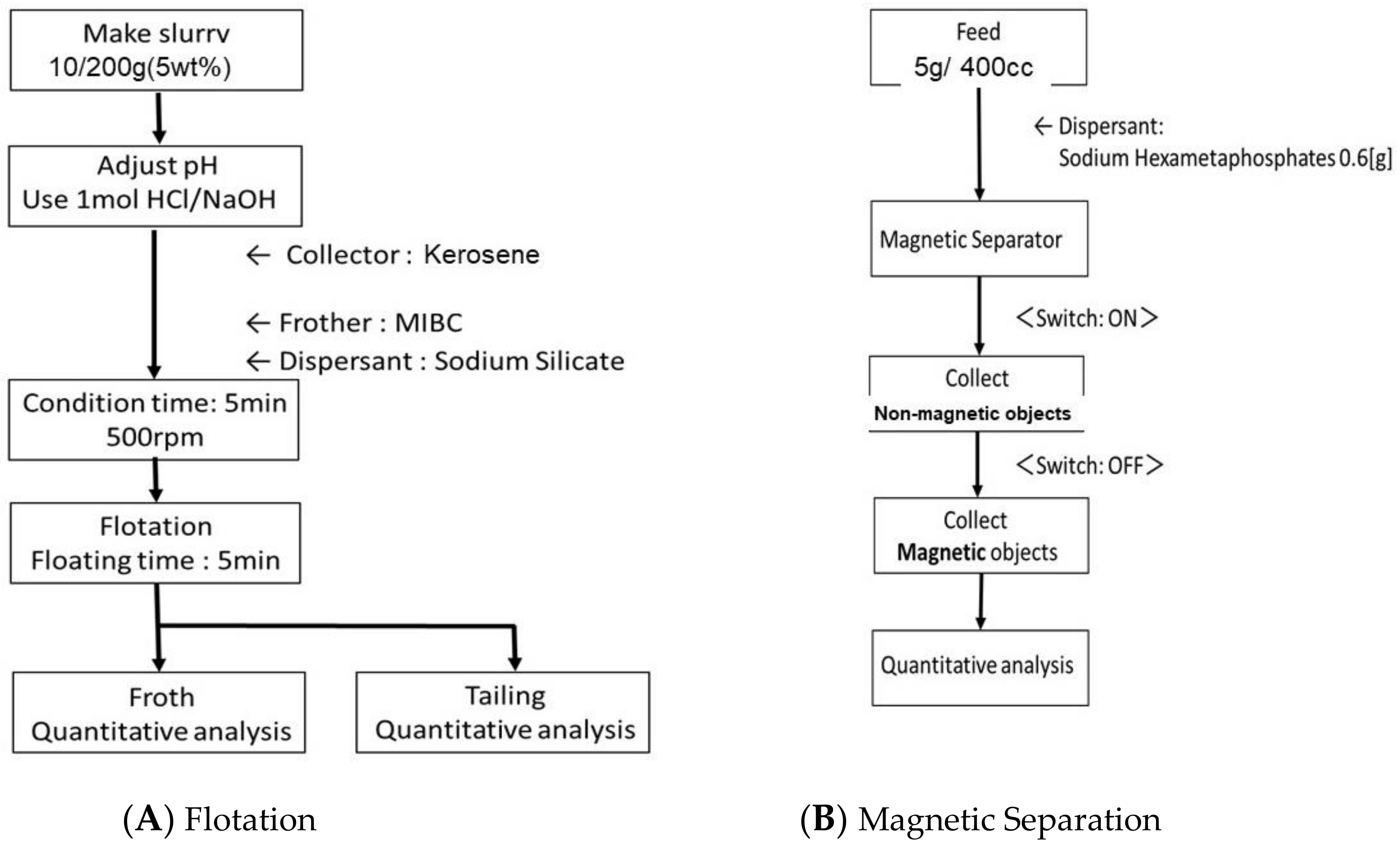
The removal of iron and sulfur impurities in shungite was studied using flotation and magnetic separation as the mineral-processing methods. In addition, microwave irradiation to remove the sulfur content was investigated. Moreover, chemical leaching using chelate and inorganic acid for sulfur and iron removal was studied. In addition, the separated silica, iron, and sulfur were analyzed through XRF, and the analytical error was 0.1% to 0.2% at 3σ [14,15].

2.2.1. Flotation

Flotation was performed in a laboratory-scale Denver flotation machine. Air was fed through a glass filter of 5 to 10 μm pore size continuously to prevent clogging. A flowsheet of the flotation is shown in Figure 6A. The pulp’s solid concentration was 5 wt%, and the pulp’s pH was 4.4. The pH was regulated using HCl and NaOH. Although the solid concentration is usually 20 to 40 wt% [16], 5 wt% was employed to increase the froth grade for preventing contamination. Furthermore, froth flotation was performed to obtain carbon particles. Kerosene is usually used as a collector for coal and carbon mineral flotation, while methyl isobutyl carbinol (MIBC) is usually used as a frother [17], and sodium silicate is used as a depressant for silica [18]. To float the carbon particles, kerosene was added as the collector; a similar procedure was conducted for coal flotation, and the effect of kerosene amount was investigated. The effect of particle size on flotation was also investigated, considering mean diameters of 11.6 μm and 4.7 μm for large and small particles, respectively (Figure 2). Moreover, during flotation, 80 g/t of MIBC was added as the frother, and 100 g/t sodium silicate was used as the dispersant. The conditioning and flotation periods were 5 min each.

2.2.2. Magnetic Separation

Magnetic separation was performed using a batch-type high-gradient magnetic separator. A matrix cell filled with several expanded ferromagnetic stainless-steel plates of 1 mm thickness was set between electromagnet poles, and the slurry was fed from the top.
The separation zone filled with the matrix was 2 × 3 cm wide and 10 cm high. The applied magnetic flux densities were set at 0.5 and 1T. A flowsheet of magnetic separation is shown in Figure 6B. The pulp solid concentration of the fed slurry was 1.25 wt%, and 0.15 wt% of hexametaphosphate was mixed into the slurry as a dispersant.

2.2.3. Microwave Irradiation

A microwave oven (1000 W MICROWAVE REACTOR: MWR-CX1) was utilized to evaporate and remove the sulfur in shungite. The relationship between irradiation time and sulfur removal was investigated, and the composition of the irradiated shungite was determined via XRD.

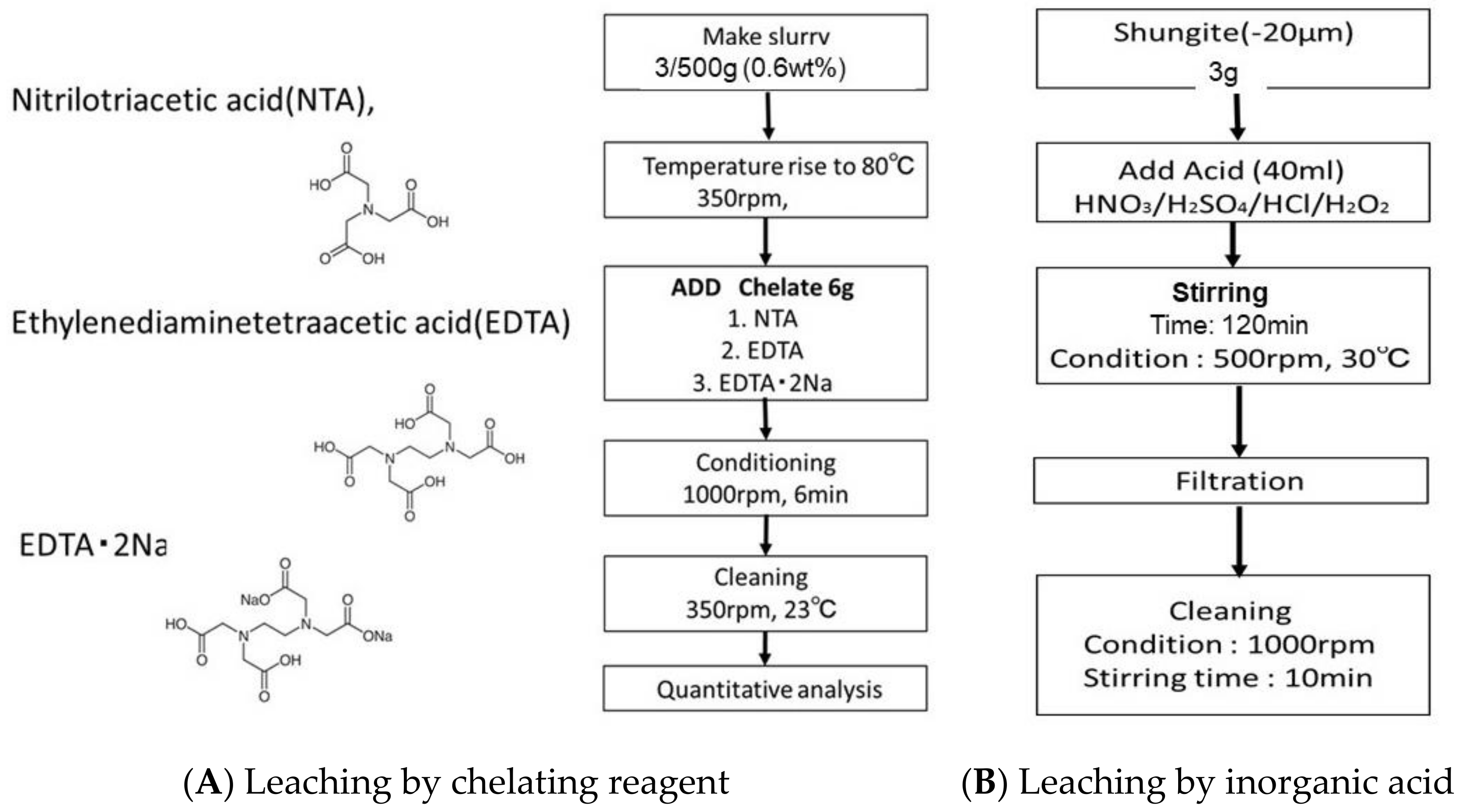
2.2.4. Leaching Using Chelating Reagent

Three kinds of chelating reagents were utilized to dissolve the heavy-metal ions in shungite: nitrilotriacetic acid (NTA), ethylenediaminetetraacetic acid (EDTA), and EDTA∙2Na. A flowsheet of chemical leaching using the chelating reagents is shown in Figure 7A. The leaching rates of iron and sulfur contents in shungite under the various reagents were compared. Here, 0.6 wt% slurry with chelate was agitated for 6 min at 80 °C.

2.2.5. Leaching Using Inorganic Acid

Various kinds of inorganic acids were added to dissolve the heavy-metal ions in shungite. A flowsheet of chemical leaching using acid is shown in Figure 7B. Nitric acid (HNO3), sulfuric acid (H2SO4), and hydrogen peroxide (H2O2) were used at different compositions, and the leaching rates of iron and sulfur contents in shungite were compared. Here, 0.6 wt% slurry with acid was agitated for 120 min at 30 °C.

3. Results and Discussion
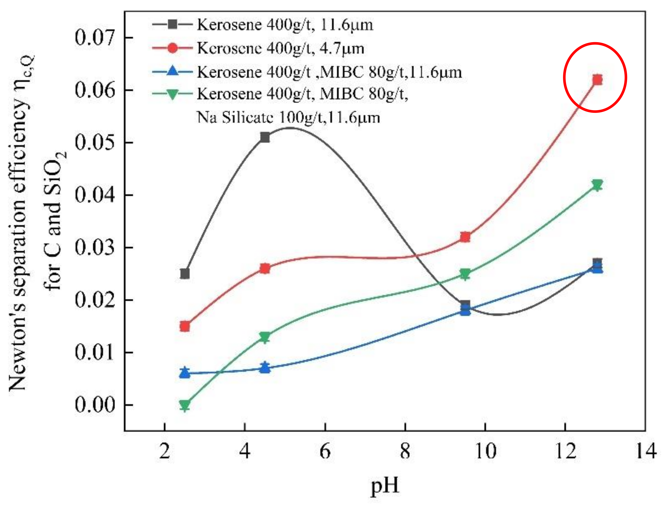
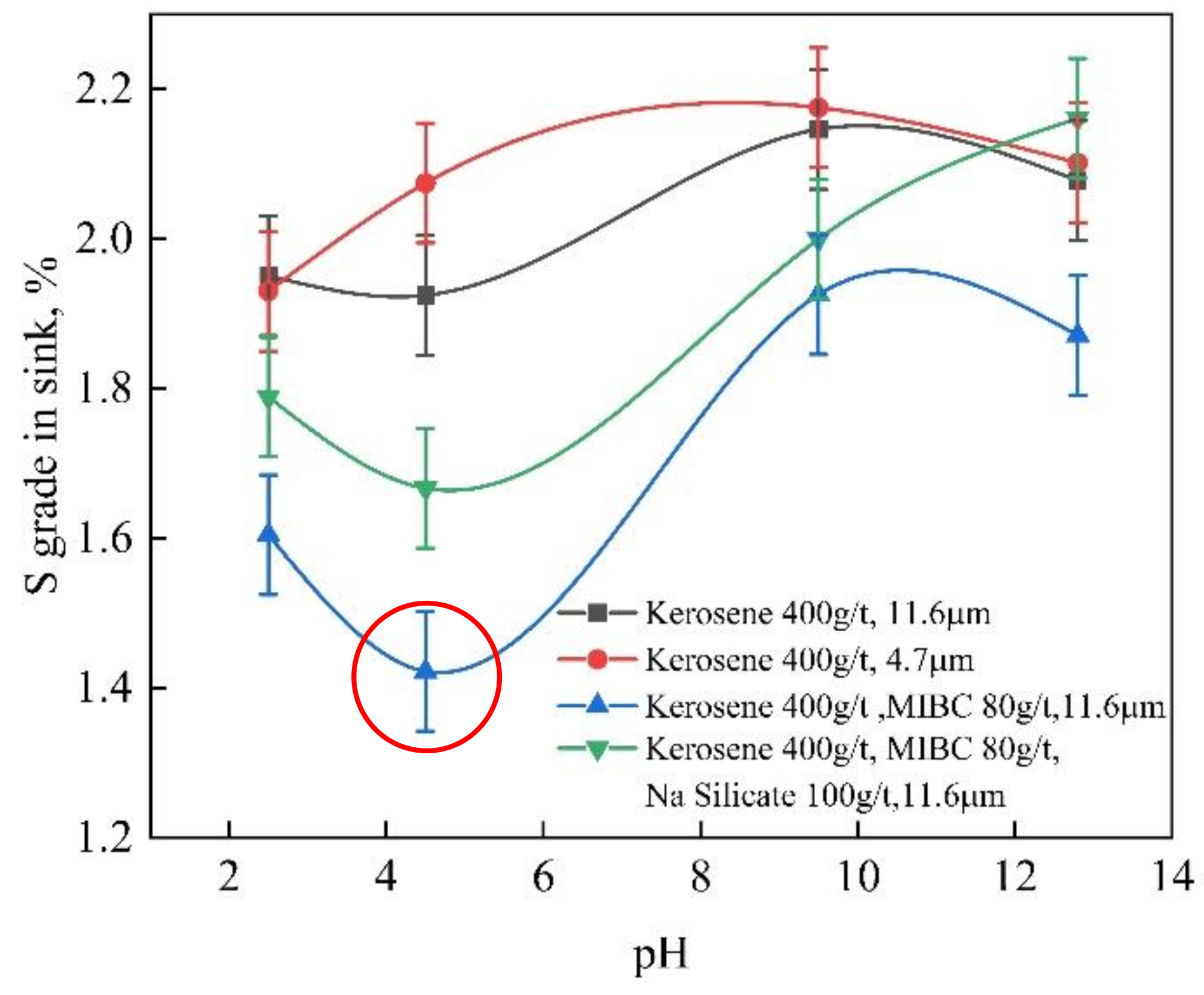
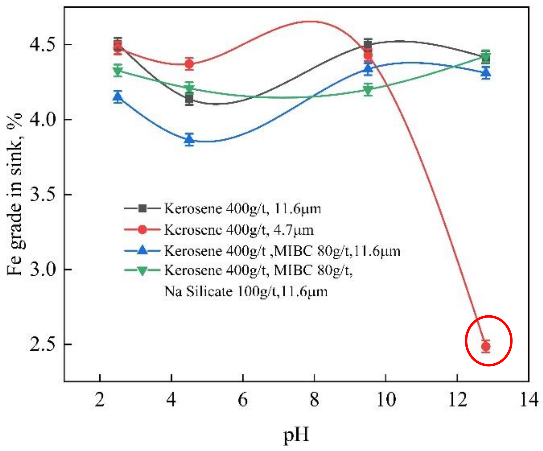
Mineral processing techniques are usually used for removing impurities; therefore, flotation and magnetic separation were first performed. The increase in the carbon percentage in the float product and the increase in the silica content in the sink product were obtained in the flotation. However, in this experiment, the purpose was the removal of sulfur and iron as impurities; therefore, the distribution of sulfur and iron in the float and sink fractions were investigated by shungite flotation.
Shungite free of harmful impurities can be utilized as a rubber filler, a component of composite materials, and a polymer binder. As shungite has a specific surface area of 30 m2/g and an average pore diameter of 14 nm, it can be used as an adsorbent for wastewater treatment. For these applications, the sulfur and iron contents of shungite, which are its main impurities, need to be removed. Thus, the following physical and chemical treatment methods were investigated.

3.1. Flotation

Flotation experiments using only kerosene; MIBC and kerosene; and MIBC, sodium silicate, and kerosene were conducted for the shungite of 11.6 μm mean size, and a flotation experiment using only kerosene was performed for the ground shungite of 4.7 μm mean size. The added kerosene amount was 400 g/t. In shungite flotation, 400 g/t obtained the largest froth fraction; moreover, this amount has been reported as the optimum kerosene amount in coal flotation [17]. As the isoelectric points of shungite and silica are pH 4 and pH 2, respectively, both carbon and silica possessed a negative charge under the adopted pH, and there was a possibility of dispersion. However, it was difficult to separate carbon and silica due to the disseminated structure of the finer μm size, as predicted in Figure 1 and Figure 4. The experimental result of flotation effectiveness is shown by Newton’s separation efficiency [19]. Equation (1) shows the formula for Newton’s separation efficiency, ηc,Q, where Rc denotes the carbon recovery in the float product, and RQ is the silica recovery in the sink product. A larger ηc,Q indicates better separation performance.
ηc,Q = Rc + RQ − 1
The effect of pH on Newton’s separation efficiency, ηc,Q, is illustrated in Figure 8. The largest separation efficiency was obtained for the flotation of fine-ground shungite of 4.7 μm mean size at pH 13. Finer grinding increases the liberation degree of carbon and silica, and the increased OH- ions at higher-alkalinity conditions, pH 13, can depress the floatability of silica. However, the ηc,Q was quite small compared with that of perfect separation (ηc,Q = 1). Both the float and sink products can be utilized if the iron and sulfur impurities are removed.
The sulfur grades in the sink products during flotation at various conditions are shown in Figure 9. The lowest sulfur grade (1.4%) was obtained at pH 4.5, flotation using MIBC and kerosene, and shungite of 11.6 μm mean size. However, the ηcQ was quite low (Figure 8). Moreover, although the sulfur grade was 1.9% at pH 4.5, flotation using only kerosene, and 11.6 μm mean size, the ηc,Q was larger.
The iron grades in the sink products at various conditions are shown in Figure 10. The lowest iron grade was 2.5%, obtained at pH 13, flotation using only kerosene, and ground shungite of 4.7 μm mean size. The ηc,Q was large (Figure 8). The increase in the liberation degree of the finer shungite caused the removal of iron in the sink product at higher-alkalinity conditions.
On the other hand, in the froth product, the largest S grade of 3.8% with 45% recovery and the largest Fe grade of 0.8% with 55% recovery were obtained at pH 13 with kerosene 400g/t and MIBC 80g/t and shungite of 11.6 μm mean size. The sulfur grade in the froth product was larger than in the sink product, and the iron grade in the froth product was smaller than in the sink product.
In the laboratory-scale Denver flotation machine, the separation size was limited. Finer-particle separation with column flotation using finer microbubbles would be a future subject.

3.2. Magnetic Separation

The magnetic separation results are listed in Table 2. The grades of iron and sulfur in nonmagnetic materials under the magnetic field intensity of 1 T (2.8% and 1.9%, respectively) were lower than those under the magnetic field intensity of 0.5 T. Iron and sulfur were captured and removed as magnetic products. The minerals’ magnetic-specific susceptibilities of FeS2, Fe2O3, C, and SiO2 are 0.98, 2000, −2.2, and −0.46 (×10−6), respectively [20]. As the iron grade of magnetics and nonmagnetics was almost the same at 0.5 and 1 T, iron oxide particles of large magnetic susceptibility, like hematite (Fe2O3), had already been captured at 0.5 T. If iron is included in weekly magnetic sulfide minerals, such as in pyrite (FeS2), a higher magnetic field and magnetic-field gradient are necessary to capture [21]. This separation result shows that half of the iron would exist as sulfide minerals. In magnetic separation, the small number of ferromagnetic particles causes nonmagnetic particles to be captured and decreases the separation efficiency. The Currie point measurement (pyrrhotite at about 320 °C and magnetite at about 580 °C) of particles is necessary to investigate the existence of ferromagnetic impurities in shungite.

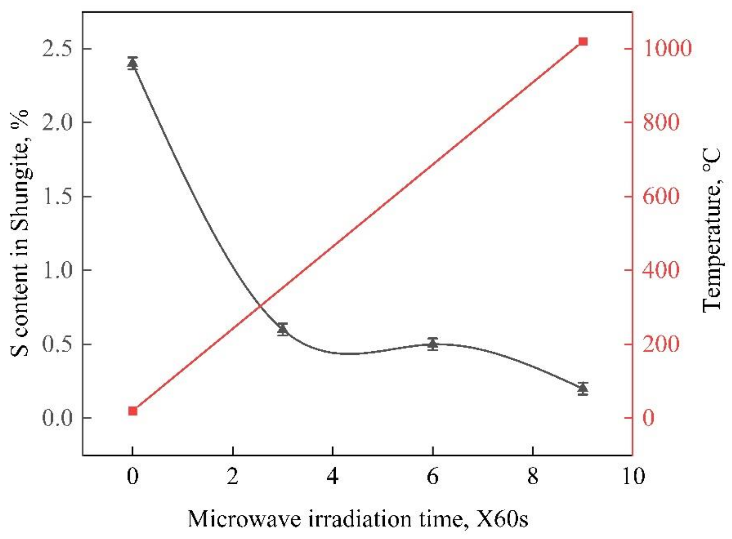
3.3. Microwave Irradiation

Sulfur removal was performed via microwave irradiation, and the result is shown with temperature in Figure 11. The 9 min microwave irradiation reduced the sulfur content in shungite to 0.2%, i.e., 92% sulfur removal. The dielectric loss for heating is shown in the next formula using electric field intensity (E), electrical conductivity (σ), frequency (ω), permittivity of vacuum ( ε o ), relative permittivity ( ε r ), and dielectric loss tangent ( t a n δ ) [22].
P = E 2 σ + ω ε o ε r t a n δ
The electrical resistivity, 1/σ, of amorphous carbon in shungite is around 1000 to 2000 μΩm and is quite small compared to other minerals. The temperature of heated sample is almost proportional to time [23]; therefore, the connected line was used in Figure 11. Irradiation caused the heating of shungite, and the temperature of shungite subjected to 9 min microwave irradiation increased to about 1000 °C. Through XRD, silicon carbide (SiC) was observed in the irradiated shungite. After 3 min of heating, the temperature increased to around 400 °C and 80% of sulfur evaporated by the decomposition of pyrite as shown in [13]. The sulfur in shungite can be easily removed via evaporation (boiling point of sulfur: 445 °C). The total weight loss of shungite was about 10% because some carbon was also incinerated with oxygen in atmospheric air.

3.4. Leaching Using Chelating Reagent

Three kinds of chelating reagents were employed for the leaching of iron and sulfur in shungite. The iron and sulfur contents in the as-received and leached shungite samples are listed in Table 3. The three kinds of chelates could decrease the iron and sulfur contents. NTA, especially, showed the largest leaching rates for iron and sulfur. The pure pyrite mineral was also leached by NTA; however, only a few percent was dissolved; therefore, the iron and sulfur compounds are different from pure pyrite. The pH of slurry leached using NTA decreased to pH 2.4. The sulfur and iron grades became 0.9% and 2.0%, respectively, i.e., 63% sulfur and 57% iron removal rates. A leaching temperature of 80 °C was adopted. When leaching was performed at room temperature, only the sulfur removal rate decreased. Other sulfur compounds, except pyrite, could be leached by the acidic chelate at 80 °C. On the other hand, when EDTA-Na was dissolved in water, the pH ranged from 4.2 to 4.8, and a smaller amount of iron was dissolved. Dissolved Fe2+ ions produced a chelate complex with the chelate. If there was no chelate, the dissolved Fe 2+ ions could be adsorbed by the carbon in shungite through increasing the pH by washing. Iron chelate complexes prevent adsorption of Fe2+ ions by carbon and can be removed from shungite by water washing. Leaching using a chelating reagent does not change the surface property of carbon compared with the utilization of strong acid; therefore, it has been used in purification to produce high-grade carbon [24].

3.5. Leaching Using Inorganic Acid

Eight kinds of inorganic acid solutions were utilized for leaching iron and sulfur in shungite. The results are presented in Table 4. The largest iron removal was obtained using an aqueous mixture of HCl and H2O2, and the Fe percentage became 0.8%. The aqueous solution of HCl with H2O2 showed 83% iron removal and 86% sulfur removal from shungite. H2O2 increased the Eh of the aqueous solution, and the sulfur and iron oxidized and dissolved well at a lower pH. For removal using a reverse aqua-regia liquid, the Fe percentage became 0.9%, and the sulfur content decreased to 0.23%. Reverse aqua regia decomposes sulfur in pyrite so that it changes to sulfate ions [25]. Reverse aqua regia removed 80% of iron and 90% of sulfur. In this experiment, the largest Fe removal was performed with the HCl and H2O2 aqueous solution, and the largest S removal was established using reverse aqua regia. The difference of both Fe and S removal rates was about 0.1%. Considering the reagent cost in inorganic-acid leaching, leaching using HCl with H2O2 aqueous solution is the most effective method to remove impurities in shungite.

4. Conclusions

In this mineralogical study on shungite, silica particles were disseminated into fine structures of micrometer size using carbon fibers, graphite and a small amount of pyrite, which contains iron and sulfur, was observed. Iron and sulfur impurity removal in shungite was performed via flotation, magnetic separation, microwave treatment, and chemical leaching, and the following results were obtained.
In flotation, kerosene was used as the carbon collector. The iron and sulfur amounts in the sink and float products of shungite of 11.6 μm mean particle size were measured. The Newton’s separation efficiency value for the ground shungite of 4.7 μm mean size was higher than that of the shungite of 11.6 μm mean size, due to the fine size of the former. Moreover, in the flotation at pH 13, the iron grade of the 4.7 μm shungite in the sink product (2.5%) was lower than that of the 11.6 μm shungite (4.6%). Furthermore, in the flotation at pH 4.5 with MIBC as the frother, sulfur removal was low, and the sulfur grade obtained was 1.4%.
In the wet high-gradient magnetic separation, at a magnetic flux density of 1 T, the grades of iron and sulfur in the nonmagnetic fraction were 2.8% and 1.9%, respectively.
The removal of sulfur was investigated via microwave heating; the sulfur content was reduced to 0.2% after 9 min irradiation, and SiC was produced by the heating reaction.
Chemical leaching experiments using chelating reagents and inorganic acids were conducted to leach iron and sulfur. The NTA reagent could reduce the iron and sulfur grades to 2.0% and 0.9%, respectively. For leaching using reverse aqua regia, the iron and sulfur grades were reduced to 0.9% and 0.23%, respectively. For leaching using a 6N HCl with H2O2 aqueous solution, the iron and sulfur grades were reduced to 0.8% and 0.34%, respectively. Overall, chemical leaching using HCl with H2O2 was the most effective, showing 83% iron removal and 86% sulfur removal from shungite of 11.6 μm mean size.

5. Patent

Some parts of this article became a Japanese patent; No. JP 6791698.

Author Contributions

Methodology, T.F. and T.A.; writing—original draft preparation, T.F. and T.A.; writing—review and editing, G.D. and H.C.; investigation, J.P. and T.A.; conceptualization, C.H., K.W. and Y.W.; analysis, C.H. and S.N.; project administration, T.F., G.D. and Y.W. All authors have read and agreed to the published version of the manuscript.

Funding

This research was funded by Asaboh Co.

Institutional Review Board Statement

Not applicable.

Informed Consent Statement

Not applicable.

Data Availability Statement

The data presented in this study are available on request from the corresponding author.

Acknowledgments

Shungite used for the experiment was supplied by K. Takano and U. Yana of Asaboh Co. We appreciate their cooperation and funding. We also thank H. Kawaguchi for the introduction of shungite. We thank LetPub (www.letpub.com (accessed on 20 December 2020)) for its linguistic assistance during the preparation of this manuscript.

Conflicts of Interest

The authors declare no conflict of interest.

References

  1. Melezhik, V.A.; Filippov, M.M.; Romashkin, A.E. A giant Palaeopoerozoic deposit of shungite in NW Russia: Genesis and practical applications. Ore Geol. Rev. 2004, 135–154. [Google Scholar] [CrossRef]
  2. Kweiecinska, B.; Pusz, S.; Krzesinska, M.; Pilawa, B. Physical properties of shungite. Int. J. Coal Geol. 2007, 71, 455–461. [Google Scholar] [CrossRef]
  3. Kovalevski, V.V.; Buseck, P.R.; Cowley, J.M. Comparison of carbon in shungite rocks to other natural carbons: An X-ray and TEM study. Carbon 2001, 39, 243–256. [Google Scholar] [CrossRef]
  4. Zenkiewicz, M.; Richert, J.; Rytlewski, P.; Richert, A. Comparative analysis of shungite and graphite effects on some properties of polylactide composites. Polym. Test. 2011, 30, 429–435. [Google Scholar] [CrossRef]
  5. Mosin, O.; Ignaov, I. The structure and composition of natural carbonaceous fullerene containing mineral shungite. Int. J. Adv. Sci. Tech. Res. 2013, 6, 9–21. [Google Scholar]
  6. Moshnikov, I.A.; Kovalevski, V.V. Composite materials-based n nanostructured shungite filler. Mater. Today Proc. 2018, 5, 25971–25975. [Google Scholar] [CrossRef]
  7. Golubev, Y.A.; Antonets, I.V.; Shcheglov, V.I. Static and dynamic conductivity of nanostructured carbonaceous shungite geomaerials. Mater. Chem. Phys. 2019, 22, 19–203. [Google Scholar]
  8. Simsek, E.B.; Balta, Z.; Demircivi, P. Novel shungite based Bi2WO carbon catalyst with high photocatalytic degradation of tetracycline under visible light irradiation. J. Photochem. Photobiol. A Chem. 2019, 380, 11189. [Google Scholar]
  9. Chou, N.H.; Pierce, N.; Lei, Y.; Peea-Lopez, N.; Fujisawa, K.; Subamanian, S.; Robinson, J.A.; Chen, G.; Omichi, K.; Rozhkov, S.S.; et al. Carbon-rich shungite as a natural resource for efficient Li-ion battery electrodes. Carbon 2018, 130, 10–111. [Google Scholar] [CrossRef]
  10. Popova, A. Crystallographic analysis of graphite by X-Ray diffraction. Coke Chem. 2017, 60, 361–365. [Google Scholar] [CrossRef]
  11. Obradović, N.; Gigov, M.; Đorđević, A.; Kern, F.; Dmitrović, S.; Matović, B.; Pavlović, V.B. Shungite—A carbon-mineral rock material: Its sinterability andpossible applications. Process. Appl. Ceram. 2019, 13, 89–97. [Google Scholar] [CrossRef] [Green Version]
  12. Shalimov, A.S.; Kovalevskii, V.V.; Obrezkov, O.N.; Yaroslavtsev, A.B. Sorptive Properties of Shungite. Inorg. Mater. 2004, 40, 364–367. [Google Scholar] [CrossRef]
  13. Cheng, H.; Liu, Q.; Huang, M.; Zhang, S.; Frost, R.L. Application of TG-FTIR to study SO2 evolved during the thermal decomposition of coal-derived pyrite. Thermochim. Acta 2013, 555, 1–6. [Google Scholar] [CrossRef] [Green Version]
  14. Tani, K.; Kawabata, H.; Chang, Q.; Sato, K.; Tatsumi, Y. Quantitative analyses of silicate rock major and trace elements by X-ray fluores-cence spectrometer: Evaluation of analytical precision and sample preparation. Front. Res. Earth Evol.. 2005, 2, pp. 1–8.
  15. Morikawa, A. Rigaku Corporation. 2016. Available online: https://www.jaima.or.jp/jp/analytical/basic/xray/wds/ (accessed on 25 February 2021).
  16. Gao, Y.; Zhang, G.; Wang, M.; Liu, D. The Critical Role of Pulp Density on Flotation Separation of Nickel-Copper Sulfide from Fine Serpentine. Minerals 2018, 8, 317. [Google Scholar] [CrossRef] [Green Version]
  17. Pradyumna, K.; Naik, P.; Reddy, S.R.; Misra, V.N. Interpretation of interaction effects and optimization of reagent dosages for fine coal flotation. Int. J. Miner. Process. 2005, 75, 83–90. [Google Scholar]
  18. Rao, D.S.; Kumar, T.; Rao, S.S.; Prabhakar, S.; Raju, G.B. Effectiveness of sodium silicate as gangue depressants in iron ore slimes flotation. Int. J. Miner. Metall. Mater. 2011, 18, 515–522. [Google Scholar] [CrossRef]
  19. Aravamudhan, S.; Premkumar, N.; Yerrapragada, S.S.; Nani, B.P.; Viswanathan, K. Separation Based on Shape Part II: Newton’s Separation Efficiency. Powder Technol. 1984, 39, 93–98. [Google Scholar] [CrossRef]
  20. Higashitani, K.; Manino, H.; Matsusaka, S. Powder Technology Handbook, 4th ed.; CRC Press USA: Boca Raton, FL, USA, 2019. [Google Scholar]
  21. Svoboda, J.; Fujita, T. Recent Developments in Magnetic Methods of Material Separation. Miner. Eng. 2003, 16, 785–792. [Google Scholar] [CrossRef]
  22. Oshima, K. Mechanism and Applications of Microwave Heating. Jpn. Soc. Color Mater. 1971, 44, 27–35. [Google Scholar] [CrossRef] [Green Version]
  23. Chandrasekaran, S.; Basak, T.; Srinivasan, R. Microwave heating characteristics of graphite based powder mixtures. Int. Commun. Heat Mass Transf. 2013, 48, 22–27. [Google Scholar] [CrossRef]
  24. Nanbu, S.; Nakamura, J.; Ito, H. Production Method of High Purity Carbon. Japanese Patent No. JP 4502618, 30 April 2010. [Google Scholar]
  25. Sulcek, Z.; Povondra, P. Methods of Decomposition in Inorganic Analysis, 1st ed.; CRC Press: Boca Raton, FL, USA, 1989; p. 27. [Google Scholar]
Figure 1. Photographs of the investigated shungite rock and ground powder and scanning electron microscopy images.
Minerals 11 00245 g001
Figure 2. Cumulative particle-size distribution of ground shungite used in this experiment. Mean diameters (median diameter D50) of large-size particles (L) and small-size particles (S): 11.6 μm and 4.7 μm, respectively.
Minerals 11 00245 g002
Figure 3. X-ray diffraction pattern of shungite powder.
Minerals 11 00245 g003
Figure 4. Elemental maps (C, O, Mg, Al, Si, S, K, Fe) of shungite, obtained via scanning electron microscopy and energy-dispersive X-ray spectroscopy.
Minerals 11 00245 g004
Figure 5. Measurement of shungite via thermogravimetry-differential thermal analysis under air conditions and at 10 °C/min.
Minerals 11 00245 g005
Figure 6. Flowsheet of mineral processing with flotation (A) and magnetic separation (B).
Minerals 11 00245 g006
Figure 7. Flowsheet of chemical leaching.
Minerals 11 00245 g007
Figure 8. Results of flotation using only kerosene for shungite of 4.7 μm and flotations using only kerosene, MIBC + kerosene, and MIBC + sodium silicate + kerosene for shungite of 11.6 μm.
Minerals 11 00245 g008
Figure 9. Sulfur grades in sink products of flotation using only kerosene for shungite of 4.7 μm and flotations using only kerosene, MIBC + kerosene, and MIBC + sodium silicate + kerosene for shungite of 11.6 μm mean size.
Minerals 11 00245 g009
Figure 10. Iron grades in sink products of flotation using only kerosene for shungite of 4.7 μm and flotations using only kerosene, MIBC + kerosene, MIBC + sodium silicate + kerosene for shungite of 11.6 μm.
Minerals 11 00245 g010
Figure 11. Change in the sulfur content of shungite with microwave irradiation time.
Minerals 11 00245 g011
Table 1. Elemental composition (weight%) of shungite.
Elementalwt%Elementalwt%
C45.4MgO0.2
SiO238.3Na2O0.1
Fe4.6PbO0.1
K2O2.5P2O50.1
Al2O32.3Cl0.1
S2.4Cr2O30.1
TiO20.5MnO0.1
CaO0.5NiO0.1
ZnO0.3ZrO20.1
CuO0.2V2O50.1
Table 2. Result of high-gradient magnetic separation.
Magnetic Field, TMagnetics, %Non-Magnetics, %
Fe GradeS GradeFe GradeS Grade
0.55.42.62.92.0
1.05.73.12.81.9
Table 3. Iron and sulfur contents in as-received and leached shungite samples.
Fe, %S, %Weight Loss, %
As-received4.62.4
NTA2.00.912.2
EDTA2.91.09.3
EDTA-2Na3.31.27.7
Table 4. Iron and sulfur contents in shungite samples leached using inorganic acids.
Fe, %S, %Weight Loss, %
As-received4.62.40
3N HNO32.20.6213.7
3N HNO3 75% + 4N H2SO4 25%1.70.6815.6
3N HNO3 50% + 4N H2SO4 50%1.70.6815.8
3N HNO3 25% + 4N H2SO4 75%1.80.7814.4
4N H2SO43.21.126.8
13N HNO3 75% + 12N HCl 25%
(Reverse aqua regia)
0.90.2322.4
6N HCl2.20.6113.4
6N HCl 95% + 30 W/V% H2O2 5%0.80.3421.7
Publisher’s Note: MDPI stays neutral with regard to jurisdictional claims in published maps and institutional affiliations.

