Low-Cost Unattended Design of Miniaturized 4 × 4 Butler Matrices with Nonstandard Phase Differences
Abstract
1. Introduction
2. Design Problem and Models of Butler Matrix Components
2.1. Design Problem
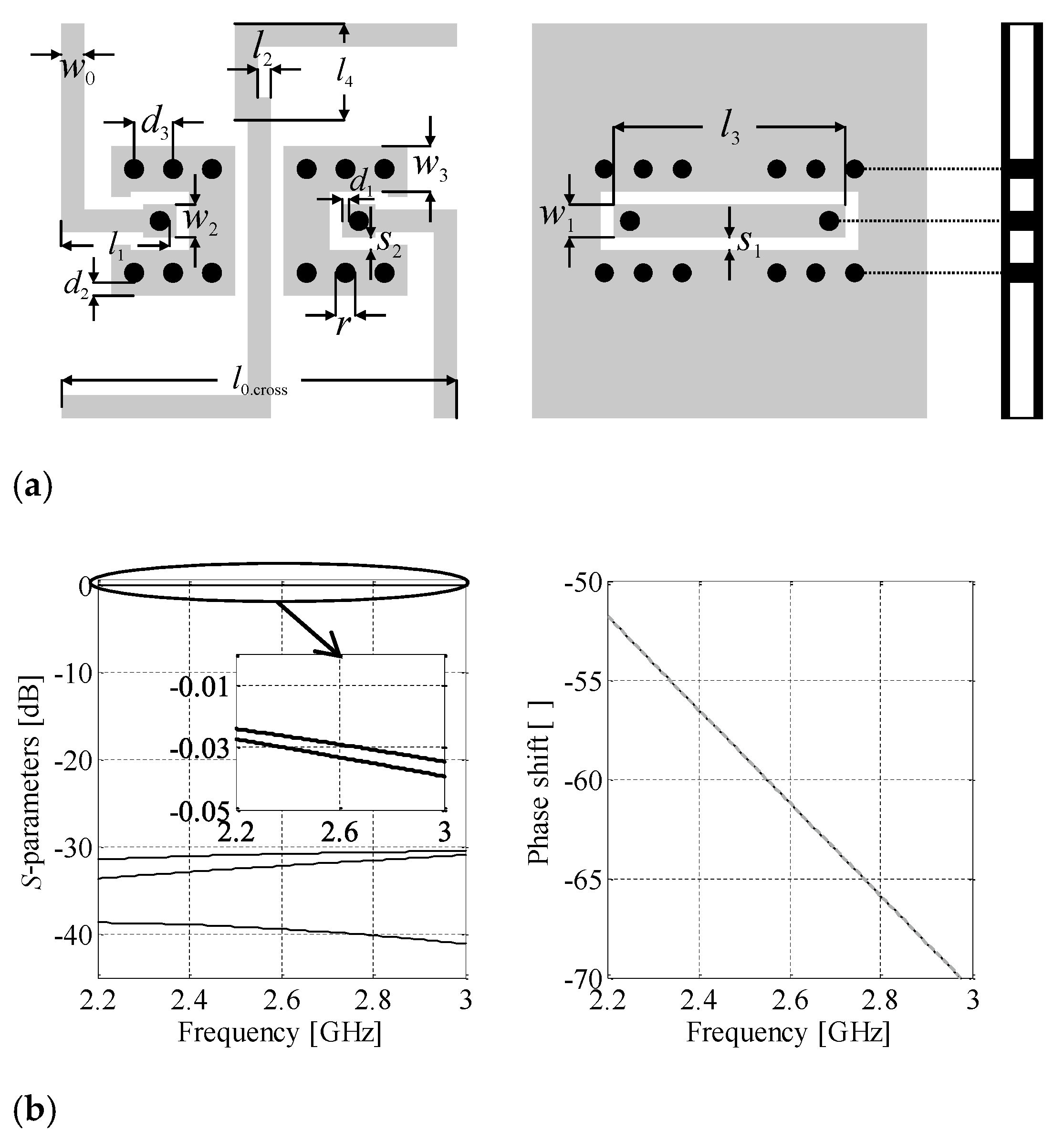
2.2. Models of Butler Matrix Components
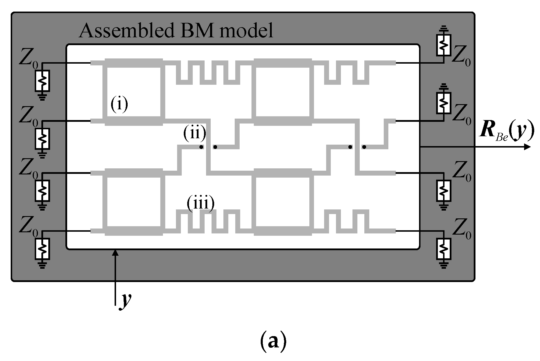
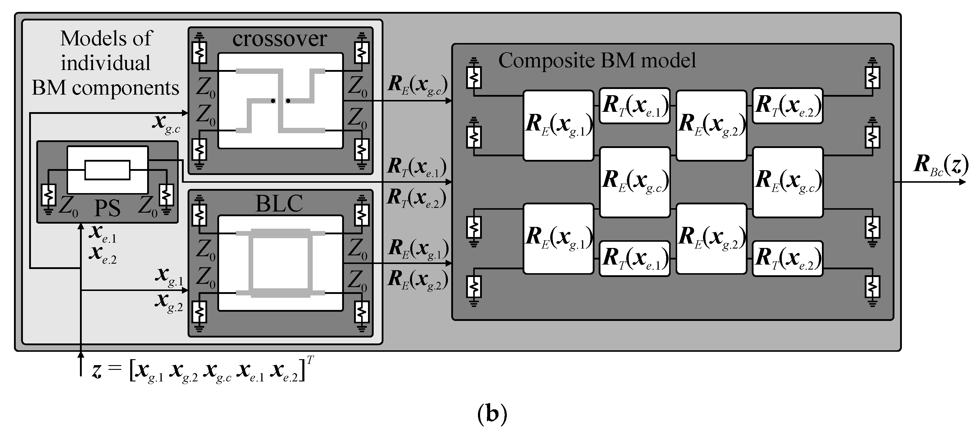
2.3. Butler Matrix Representations
2.4. Optimization Algorithms
2.4.1. Trust-Region-Based Optimization
2.4.2. Bisection-Based Heuristic
- Set i = 0, x0.1, and x0.2; set Δx = |x0.1 − x0.2|; set x(0) = 0.5(x0.1 + x0.2).
- Generate interval [x1(i), x2(i)] around the point x(i), where x1(i) = x(i) − αΔx and x2(i) = x(i) + αΔx.
- If U(x1(i))U(x2(i)) ≥ 0, set , i = i + 1 and go to step 2; otherwise go to step 4.
- Set x(i+1) = 0.5(x1(i) + x2(i)), x1(i+1) = x1(i), x2(i+1) = x2(i), i = i + 1.
- If U(x1(i))U(x(i)) < 0, set x2(i) = x(i) and go to step 7; otherwise go to step 6.
- If U(x(i))U(x2(i)) < 0, set x1(i) = x(i) and go to step 7.
- If |x(i) − x(i−1)| ≤ ε, set x* = x(i) and END; otherwise go to step 4.
3. Methodology
3.1. Synthesis of Butler Matrix and Its Components
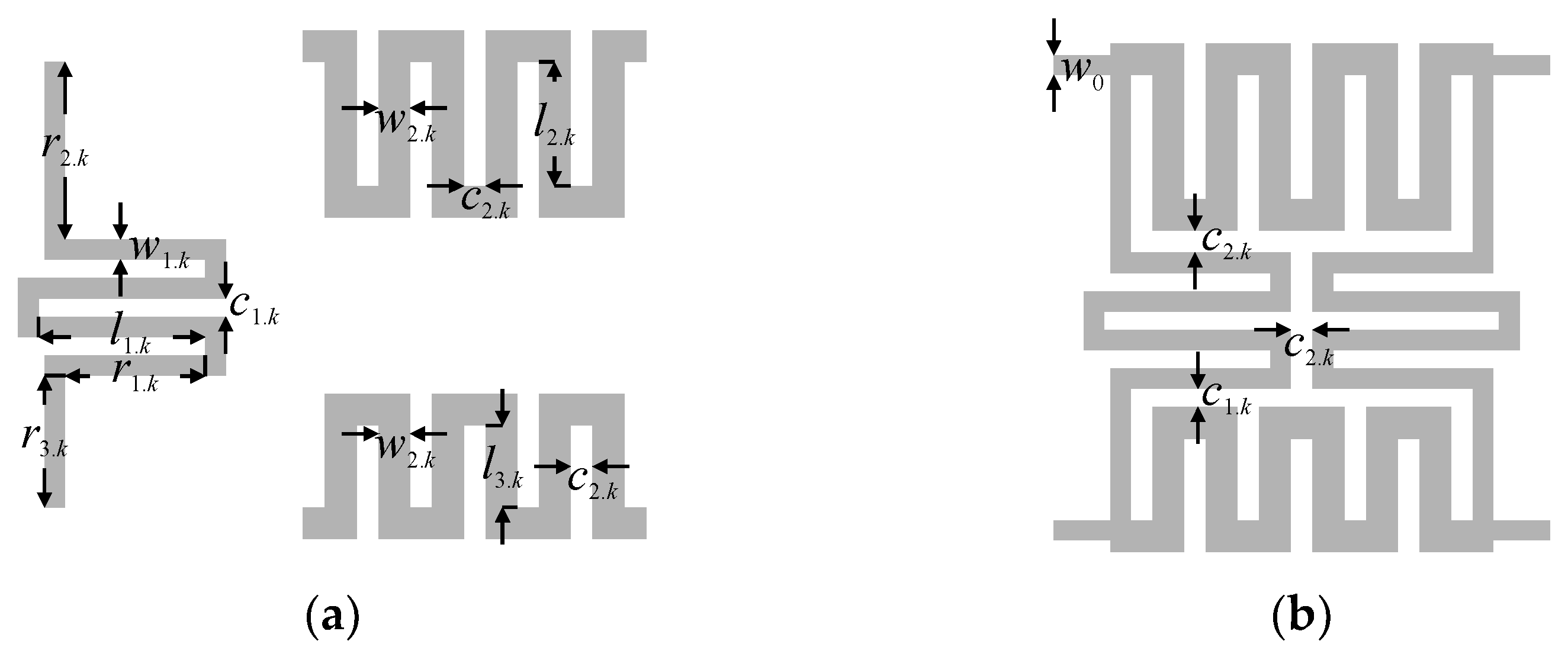
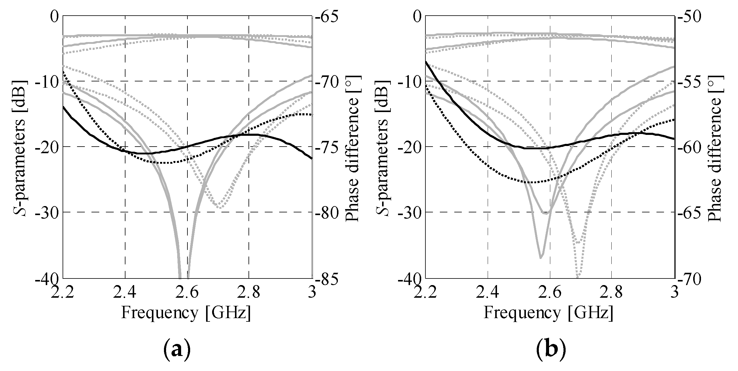
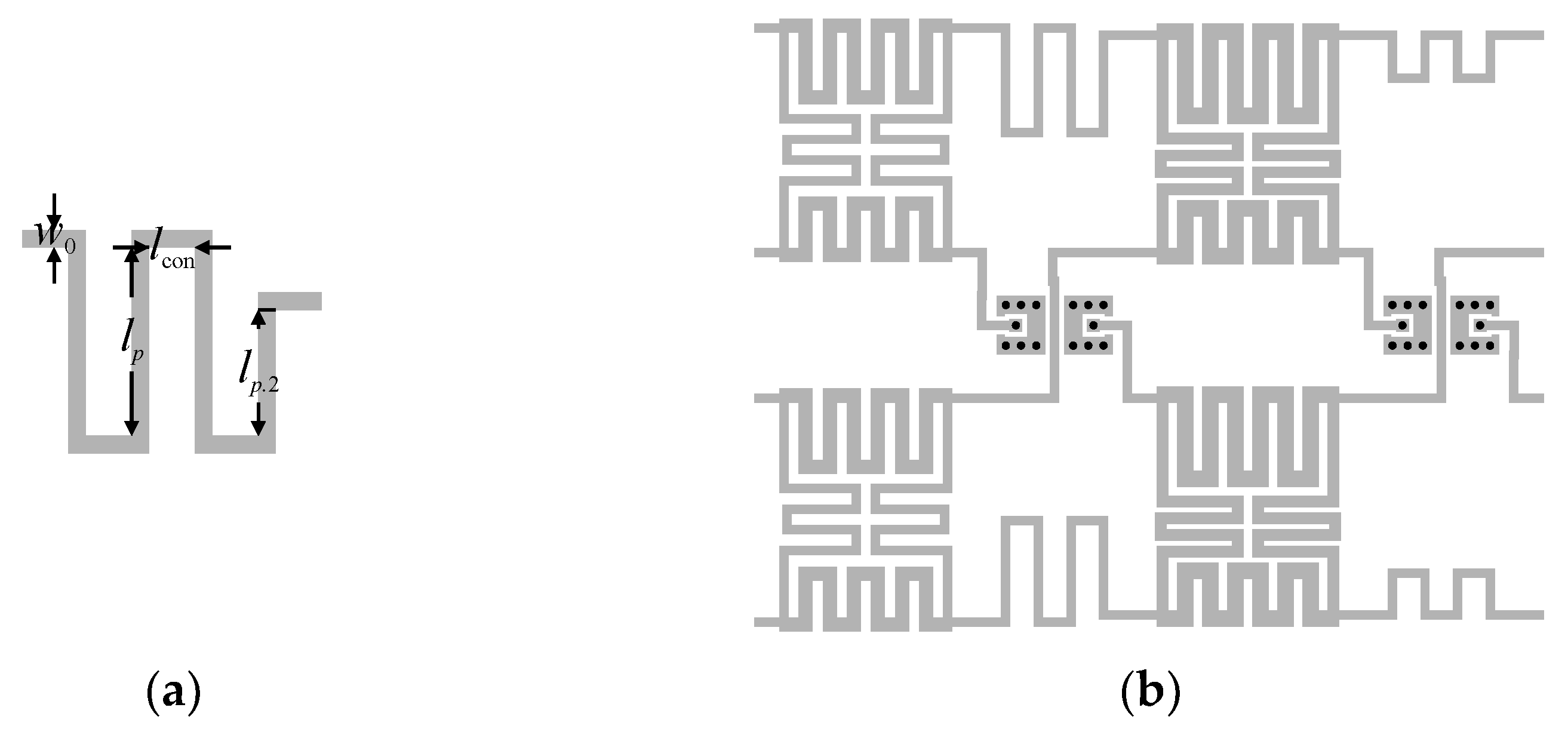
3.2. Sequential Design of BM Components
- Decompose ideal BLC model to individual TLs.
- Use electrical parameters of TLs as the reference for development of miniaturized BLC sections.
- Optimize the BLC sections to match electrical parameters of the reference TLs.
- Construct miniaturized BLC using the optimized cells and define the vector of its design parameters xg.k.
- Optimize compact BLC using objective function (11) and algorithm of Section 2.4.1.
3.3. Butler Matrix Optimization and Fine-Tuning
3.4. Summary of the Design Framework
- Define the desired performance of the Butler matrix.
- Perform synthesis of the BM structure using (4)–(6).
- Perform fine-tuning of the crossover to match length of its TLs and extract βc (cf. Section 3.2).
- Use (7), (9), (10) to synthesize the BLCs.
- Adjust performance of synthesized BLCs through minimization of (11).
- Set k = 1.
- Perform topology development of kth miniaturized BLC and optimize its EM model.
- If k = 2, go to step 9; otherwise set k = k + 1 and go to step 7.
- Optimize ideal models of phase shifters through minimization of (12), set p = 1.
- Generate initial dimensions of pth PS and optimize its EM model (cf. Section 3.2).
- If p = 4, go to step 12; otherwise set p = p + 1 and go to step 10.
- Optimize composite model of the BM.
- Perform fine-tuning of the BM.
4. Numerical Results and Experiment
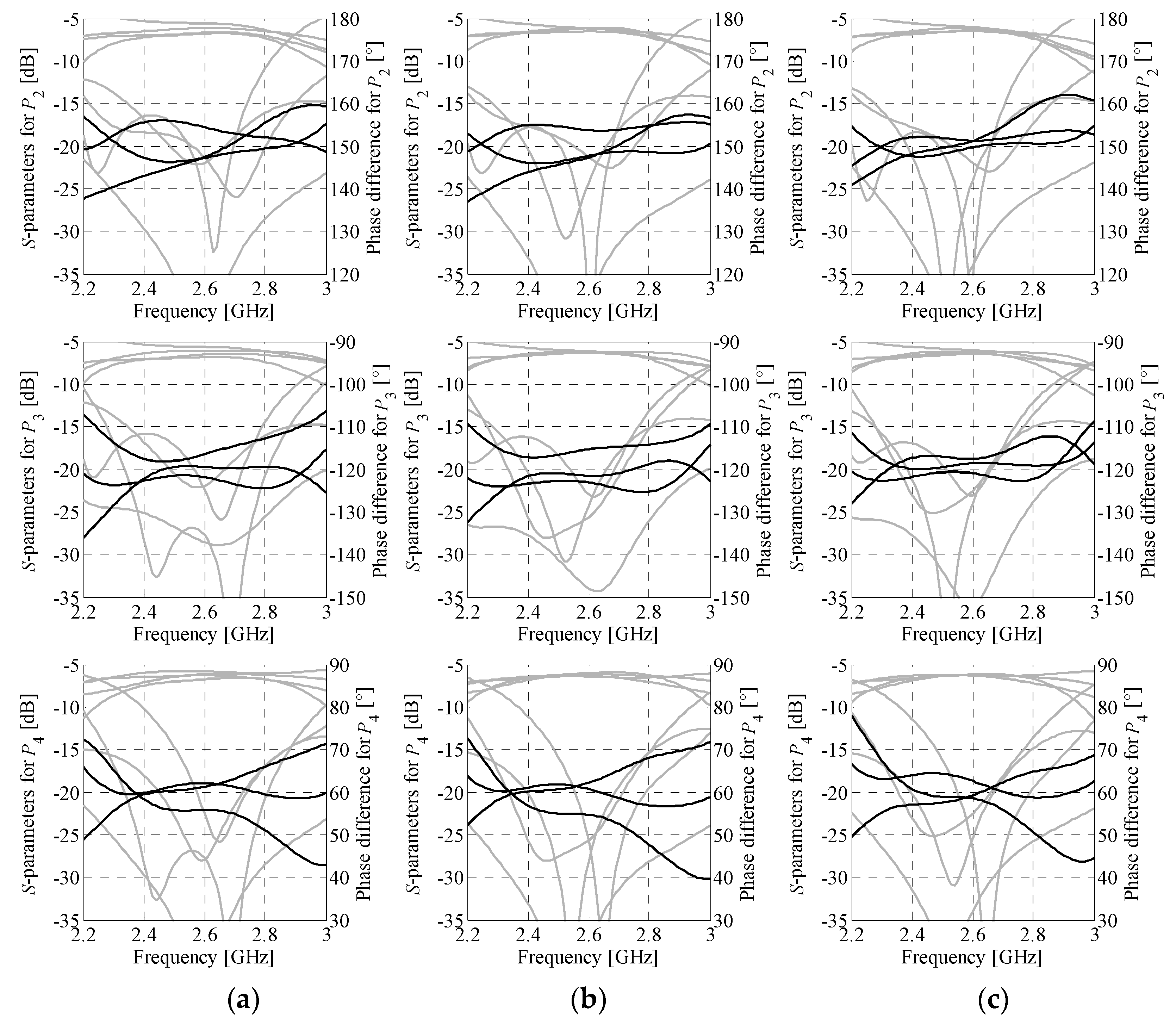
4.1. Butler Matrix 1
4.2. Butler Matrix 2
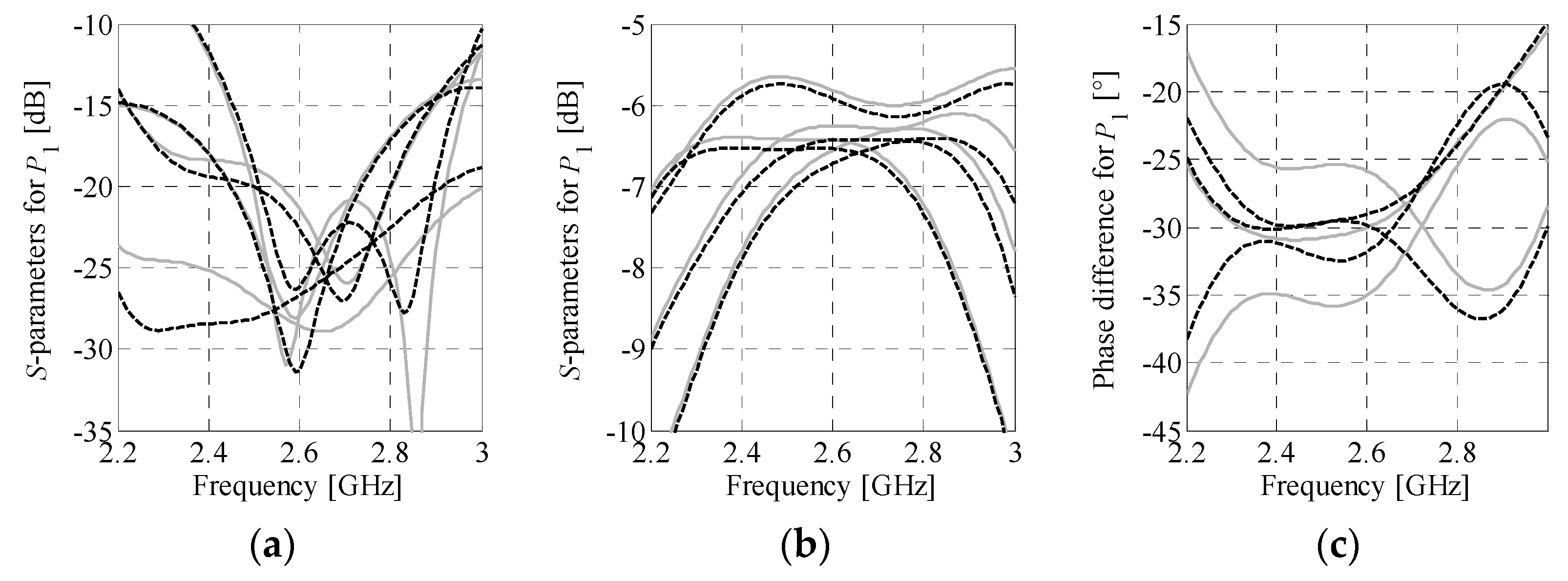
4.3. Numerical and Experimental Validation
4.4. Comparison with Benchmark Structures
5. Conclusions
Author Contributions
Funding
Institutional Review Board Statement
Informed Consent Statement
Data Availability Statement
Conflicts of Interest
References
- Song, C.; Pan, L.; Jiao, Y.; Jia, J. A High-Performance Transmitarray Antenna with Thin Metasurface for 5G Communication Based on PSO (Particle Swarm Optimization). Sensors 2020, 20, 4460. [Google Scholar] [CrossRef] [PubMed]
- Naqvi, S.I.; Hussain, N.; Iqbal, A.; Rahman, M.; Forsat, M.; Mirjavadi, S.S.; Amin, Y. Integrated LTE and Millimeter-Wave 5G MIMO Antenna System for 4G/5G Wireless Terminals. Sensors 2020, 20, 3926. [Google Scholar] [CrossRef] [PubMed]
- Lian, R.; Wang, Z.; Yin, Y.; Wu, J.; Song, X. Design of a Low-Profile Dual-Polarized Stepped Slot Antenna Array for Base Station. IEEE Antennas Wirel. Propag. Lett. 2016, 15, 362–365. [Google Scholar] [CrossRef]
- Alhalabi, R.A.; Rebeiz, G.M. High-Efficiency Angled-Dipole Antennas for Millimeter-Wave Phased Array Applications. IEEE Trans. Antennas Propag. 2008, 56, 3136–3142. [Google Scholar] [CrossRef]
- Rafii, V.; Nourinia, J.; Ghobadi, C.; Pourahmadazar, J.; Virdee, B.S. Broadband Circularly Polarized Slot Antenna Array Using Sequentially Rotated Technique for CC-Band Applications. IEEE Antennas Wirel. Propag. Lett. 2013, 12, 128–131. [Google Scholar] [CrossRef]
- Ojaroudiparchin, N.; Shen, M.; Zhang, S.; Pedersen, G.F. A Switchable 3-D-Coverage-Phased Array Antenna Package for 5G Mobile Terminals. IEEE Antennas Wirel. Propag. Lett. 2016, 15, 1747–1750. [Google Scholar] [CrossRef]
- Hansen, R.C. Phased Array Antennas, 2nd ed.; Wiley: Hoboken, NJ, USA, 2009. [Google Scholar]
- Ogurtsov, S.; Koziel, S. Systematic Approach To Sidelobe Reduction In Linear Antenna Arrays Through Corporate-Feed-Controlled Excitation. IET Microw. Antennas Propag. 2017, 11, 779–786. [Google Scholar] [CrossRef]
- Ogurtsov, S.; Koziel, S. On Alternative Approaches to Design of Corporate Feeds for Low-Sidelobe Microstrip Linear Arrays. IEEE Trans. Antennas Propag. 2018, 66, 3781–3786. [Google Scholar] [CrossRef]
- Ogurtsov, S.; Koziel, S. A Conformal Circularly Polarized Series-Fed Microstrip Antenna Array Design. IEEE Trans. Antennas Propag. 2019, 68, 873–881. [Google Scholar] [CrossRef]
- Chu, H.; Li, P.; Guo, Y.-X. A Beam-Shaping Feeding Network in Series Configuration for Antenna Array With Cosecant-Square Pattern and Low Sidelobes. IEEE Antennas Wirel. Propag. Lett. 2019, 18, 742–746. [Google Scholar] [CrossRef]
- Slomian, I.; Piekarz, I.; Wincza, K.; Gruszczynski, S. Microstrip Antenna Array With Series Feeding Network Designed With the Use of Slot-Coupled Three-Way Power Divider. IEEE Antennas Wirel. Propag. Lett. 2012, 11, 667–670. [Google Scholar] [CrossRef]
- Wincza, K.; Gruszczynski, S. Microstrip Antenna Arrays Fed by a Series-Parallel Slot-Coupled Feeding Network. IEEE Antennas Wirel. Propag. Lett. 2011, 10, 991–994. [Google Scholar] [CrossRef]
- Al Abbas, E.; Abbosh, A.M.; Bialkowski, K. Tunable In-Phase Power Divider for 5G Cellular Networks. IEEE Microw. Wirel. Compon. Lett. 2017, 27, 551–553. [Google Scholar] [CrossRef]
- Huang, Y.; Wu, K.-L.; Fang, D.-G.; Ehlert, M. An Integrated LTCC Millimeter-Wave Planar Array Antenna With Low-Loss Feeding Network. IEEE Trans. Antennas Propag. 2005, 53, 1232–1234. [Google Scholar] [CrossRef]
- Kim, S.; Yoon, S.; Lee, Y.; Shin, H. A Miniaturized Butler Matrix Based Switched Beamforming Antenna System in a Two-Layer Hybrid Stackup Substrate for 5G Applications. Electronics 2019, 8, 1232. [Google Scholar] [CrossRef]
- Park, Y.; Bang, J.; Choi, J. Dual-Circularly Polarized 60 GHz Beam-Steerable Antenna Array with 8 × 8 Butler Matrix. Appl. Sci. 2020, 10, 2413. [Google Scholar] [CrossRef]
- Kim, Y.-J.; Kim, Y.-B.; Dong, H.-J.; Cho, Y.S.; Lee, H.L. Compact Switched-Beam Array Antenna with a Butler Matrix and a Folded Ground Structure. Electronics 2019, 9, 2. [Google Scholar] [CrossRef]
- Tajik, A. Shafiei Alavijehm A.; Fakharzadeh, M. Asymmetrical 4 × 4 Butler Matrix and Its Application For Single Layer 8 x 8 Butler Matrix. IEEE Trans. Ant. Prop. 2019, 67, 5372–5379. [Google Scholar] [CrossRef]
- Liu, C.; Xiao, S.; Guo, Y.-X.; Tang, M.-C.; Bai, Y.-Y.; Wang, B.-Z. Circularly Polarized Beam-Steering Antenna Array With Butler Matrix Network. IEEE Antennas Wirel. Propag. Lett. 2011, 10, 1278–1281. [Google Scholar] [CrossRef]
- Balanis, C.A. Modern Antenna Handbook; John Wiley & Sons: New York, NY, USA, 2008. [Google Scholar]
- Tseng, C.-H.; Chen, C.-J.; Chu, T.-H. A Low-Cost 60-GHz Switched-Beam Patch Antenna Array with Butler Matrix Network. IEEE Antennas Wirel. Propag. Lett. 2008, 7, 432–435. [Google Scholar] [CrossRef]
- Ren, H.; Arigong, B.; Zhou, M.; Ding, J.; Zhang, H. A Novel Design of 4×4 Butler Matrix with Relatively Flexible Phase Differences. IEEE Antennas Wirel. Propag. Lett. 2015, 15, 1277–1280. [Google Scholar] [CrossRef]
- Moody, H. The Systematic Design of The Butler Matrix. IRE Trans. Antennas Propag. 2004, 12, 786–788. [Google Scholar] [CrossRef]
- Der, E.T.; Jones, T.R.; Daneshmand, M. Miniaturized 4 × 4 Butler Matrix and Tunable Phase Shifter Using Ridged Half-Mode Substrate Integrated Waveguide. IEEE Trans. Microw. Theory Tech. 2020, 68, 3379–3388. [Google Scholar] [CrossRef]
- Ali, A.A.M.; Fonseca, N.J.G.; Coccetti, F.; Aubert, H. Design and Implementation of Two-Layer Compact Wideband Butler Matrices in SIW Technology for Ku-Band Applications. IEEE Trans. Antennas Propag. 2010, 59, 503–512. [Google Scholar] [CrossRef]
- Tian, G.; Yang, J.-P.; Wu, W. A Novel Compact Butler Matrix Without Phase Shifter. IEEE Microw. Wirel. Compon. Lett. 2014, 24, 306–308. [Google Scholar] [CrossRef]
- Xu, H.-X.; Wang, G.-M.; Wang, X. Compact Butler Matrix Using Composite Right/Left Handed Transmission Line. Electron. Lett. 2011, 47, 1081. [Google Scholar] [CrossRef]
- Koziel, S.; Kurgan, P. Low-Cost Optimization Of Compact Branch-Line Couplers And Its Application To Miniaturized Butler Matrix Design. In Proceedings of the 44th European Microwave Conference, Rome, Italy, 6–9 October 2014; pp. 227–230. [Google Scholar] [CrossRef]
- Letavin, D.A.; Shabunin, S.N. Construction of a 4x4 Butler Microstrip Matrix with Reduced Dimensions. In Proceedings of the 2020 Ural Symposium on Biomedical Engineering, Radioelectronics and Information Technology (USBEREIT), Yekaterinburg, Russia, 14–15 May 2020; pp. 257–260. [Google Scholar] [CrossRef]
- Karamzadeh, S.; Rafii, V.; Kartal, M.; Virdee, B.S. Compact and Broadband 4 × 4 SIW Butler Matrix With Phase and Magnitude Error Reduction. IEEE Microw. Wirel. Compon. Lett. 2015, 25, 772–774. [Google Scholar] [CrossRef]
- Lian, J.-W.; Ban, Y.-L.; Xiao, C.; Yu, Z.-F. Compact Substrate-Integrated 4 × 8 Butler Matrix With Sidelobe Suppression for Millimeter-Wave Multibeam Application. IEEE Antennas Wirel. Propag. Lett. 2018, 17, 928–932. [Google Scholar] [CrossRef]
- Bhowmik, P.; Moyra, T. Modelling and Validation of a Compact Planar Butler Matrix by Removing Crossover. Wirel. Pers. Commun. 2017, 27, 788–5132. [Google Scholar] [CrossRef]
- Tseng, C.-H.; Chang, C.-L. A Rigorous Design Methodology for Compact Planar Branch-Line and Rat-Race Couplers With Asymmetrical T-Structures. IEEE Trans. Microw. Theory Tech. 2012, 60, 2085–2092. [Google Scholar] [CrossRef]
- Ren, H.; Zhou, M.; Zhang, H.; Arigong, B. A Novel Dual-Band Zero-Phase True Crossover With Arbitrary Port Impedance. IEEE Microw. Wirel. Components Lett. 2019, 29, 29–31. [Google Scholar] [CrossRef]
- Chu, H.N.; Ma, T.-G. An Extended 4×4 Butler Matrix With Enhanced Beam Controllability and Widened Spatial Coverage. IEEE Trans. Microw. Theory Tech. 2018, 66, 1301–1311. [Google Scholar] [CrossRef]
- Tseng, C.-H.; Chen, H.-J. Compact Rat-Race Coupler Using Shunt-Stub-Based Artificial Transmission Lines. IEEE Microw. Wirel. Compon. Lett. 2008, 18, 734–736. [Google Scholar] [CrossRef]
- Ahmed, O.; Sebak, A.; Denidni, T. Compact UWB Printed Monopole Loaded With Dielectric Resonator Antenna. Electron. Lett. 2011, 47, 7–8. [Google Scholar] [CrossRef]
- Lin, C.-C. Compact Bow-Tie Quasi-Self-Complementary Antenna for UWB Applications. IEEE Antennas Wirel. Propag. Lett. 2012, 11, 987–989. [Google Scholar] [CrossRef]
- Koziel, S.; Ciaurri, D.E.; Leifsson, L. Surrogate-Based Methods. In Computational Optimization, Methods and Algorithms. Studies in Computational Intelligence; Koziel, S., Yang, X.S., Eds.; Springer: Berlin/Heidelberg, Germany, 2011; Volume 356, pp. 33–59. [Google Scholar]
- Leal-Romo, F.D.J.; Rayas-Sanchez, J.E.; Chavez-Hurtado, J.L. Surrogate-Based Analysis and Design Optimization of Power Delivery Networks. IEEE Trans. Electromagn. Compat. 2020, 62, 2528–2537. [Google Scholar] [CrossRef]
- Feng, F.; Na, W.; Liu, W.; Yan, S.; Zhu, L.; Ma, J.; Zhang, Q.-J. Multifeature-Assisted Neuro-transfer Function Surrogate-Based EM Optimization Exploiting Trust-Region Algorithms for Microwave Filter Design. IEEE Trans. Microw. Theory Tech. 2020, 68, 531–542. [Google Scholar] [CrossRef]
- Pozar, D.M. Microwave Engineering, 4th ed.; John Wiley & Sons: Hoboken, NJ, USA, 2012. [Google Scholar]
- Hong, J.; Lancaster, M.J. Microstrip Filters for RF/Microwave Applications; Wiley: New York, NY, USA, 2001. [Google Scholar]
- Conn, A.R.; Gould, N.I.M.; Toint, P.L. Trust Region Methods; Society for Industrial & Applied Mathematics (SIAM): Philadelphia, PA, USA, 2000. [Google Scholar]
- Bekasiewicz, A. Low-Cost Automated Design of Compact Branch-Line Couplers. Sensors 2020, 20, 3562. [Google Scholar] [CrossRef]
- Arfken, G. Mathematical Methods for Physicists, 3rd ed.; Academic Press: Orlando, FL, USA, 1985. [Google Scholar]
- Wong, Y.S.; Zheng, S.Y.; Chan, W.S. Quasi-arbitrary phase-difference hybrid coupler. IEEE Trans. Microw. Theory Tech. 2012, 60, 1530–1539. [Google Scholar] [CrossRef]
- Deb, K. Multi-Objective Optimization Using Evolutionary Algorithms; John Wiley Sons, Ltd.: Hoboken, NJ, USA, 2001; p. 497. [Google Scholar]
- Coello, C.A.C.; Van Veldhuizen, D.A.; Lamont, G.B. Evolutionary Algorithms for Solving Multi-Objective Problems; Springer Science and Business Media LLC: New York, NY, USA, 2002. [Google Scholar]
- Kurgan, P.; Filipcewicz, J.; Kitlinski, M. Development of a Compact Microstrip Resonant Cell Aimed at Efficient Microwave Component Size Reduction. IET Microw. Antennas Propag. 2012, 6, 1291. [Google Scholar] [CrossRef]
- Tajik, A.; Fakharzadeh, M.; Mehrany, K. DC to 40-GHz Compact Single-Layer Crossover. IEEE Microw. Wirel. Compon. Lett. 2018, 28, 642–644. [Google Scholar] [CrossRef]
- Ding, K.; Kishk, A.A. 2-D Butler Matrix and Phase-Shifter Group. IEEE Trans. Microw. Theory Tech. 2018, 66, 5554–5562. [Google Scholar] [CrossRef]
- Hassan, A.T.; Kishk, A.A. Efficient Procedure to Design Large Finite Array and Its Feeding Network With Examples of ME-Dipole Array and Microstrip Ridge Gap Waveguide Feed. IEEE Trans. Antennas Propag. 2020, 68, 4560–4570. [Google Scholar] [CrossRef]
- Mroczka, J. The Cognitive Process in Metrology. Measurement 2013, 46, 2896–2907. [Google Scholar] [CrossRef]
- Chen, B.; He, J.; Guo, Y.; Pan, S.; Ye, X.; Fan, J. Multi-Ports ([2n) 2×-Thru De-Embedding: Theory, Validation, and Mode Conversion Characterization. IEEE Trans. Electromagn. Compat. 2019, 61, 1261–1270. [Google Scholar] [CrossRef]
- Ji, B.; Chen, Z.; Chen, S.; Zhou, B.; Li, C.; Wen, H. Joint Optimization for Ambient Backscatter Communication System With Energy Harvesting for IoT. Mech. Syst. Signal Process. 2020, 135, 106412. [Google Scholar] [CrossRef]



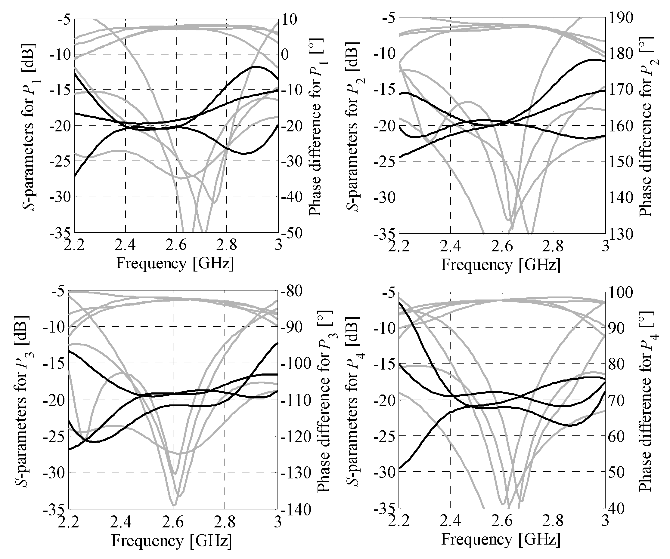
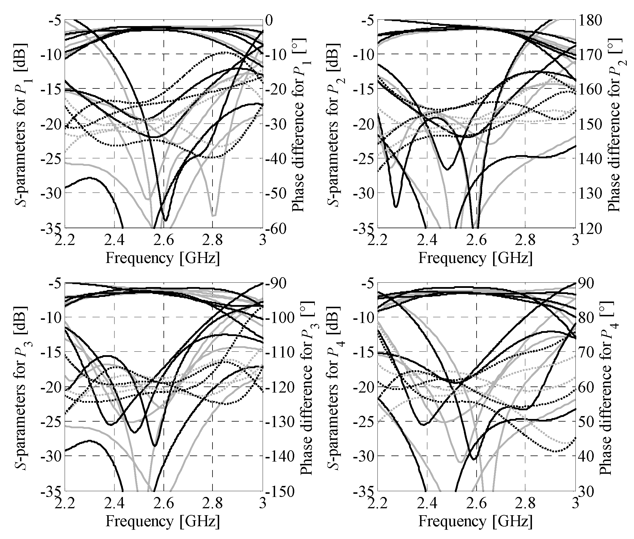
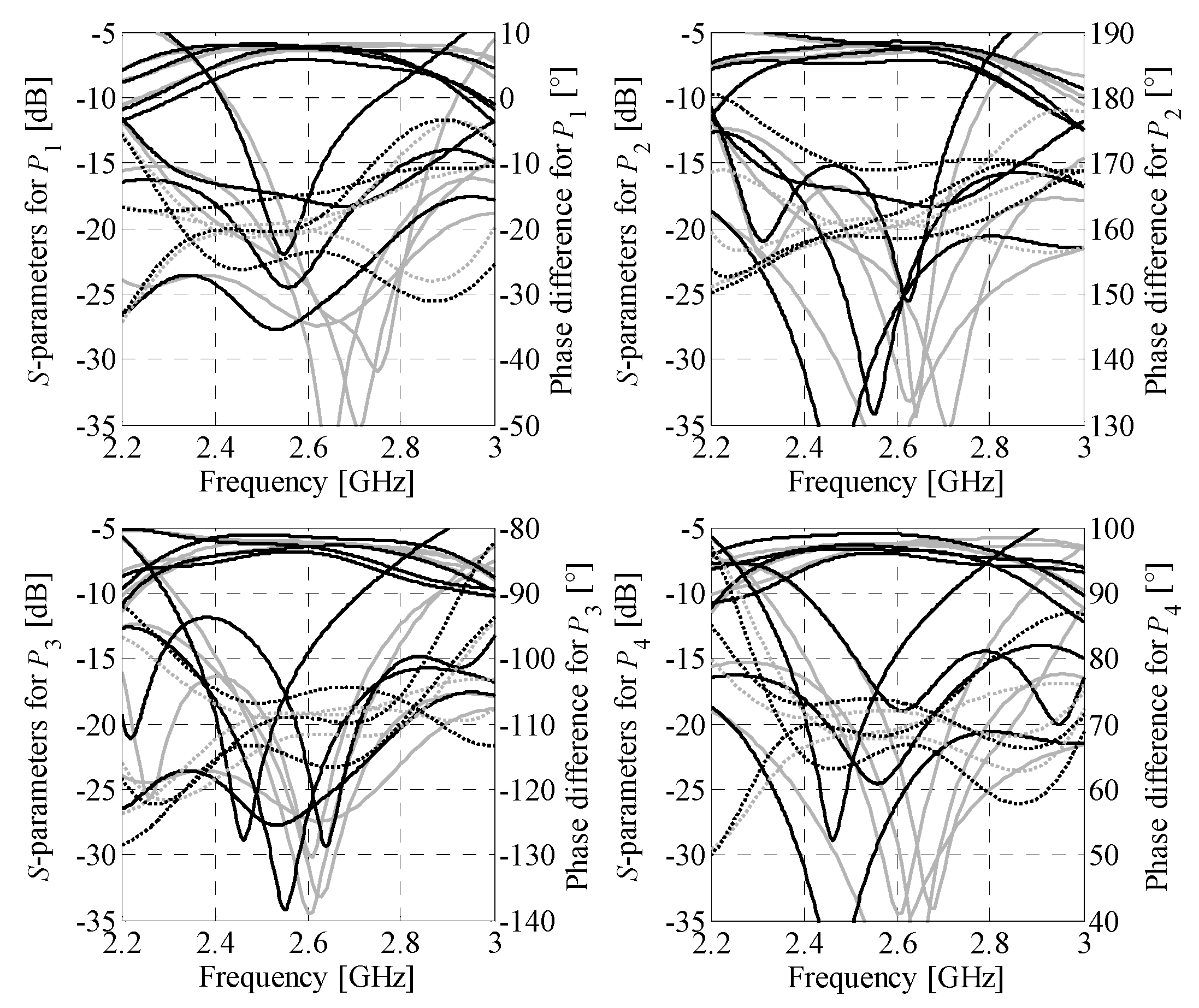
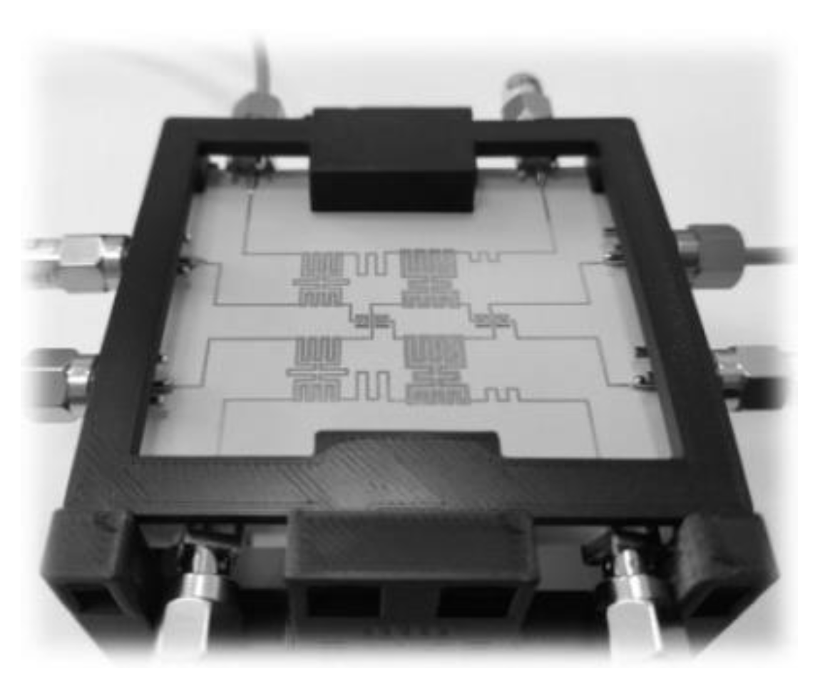
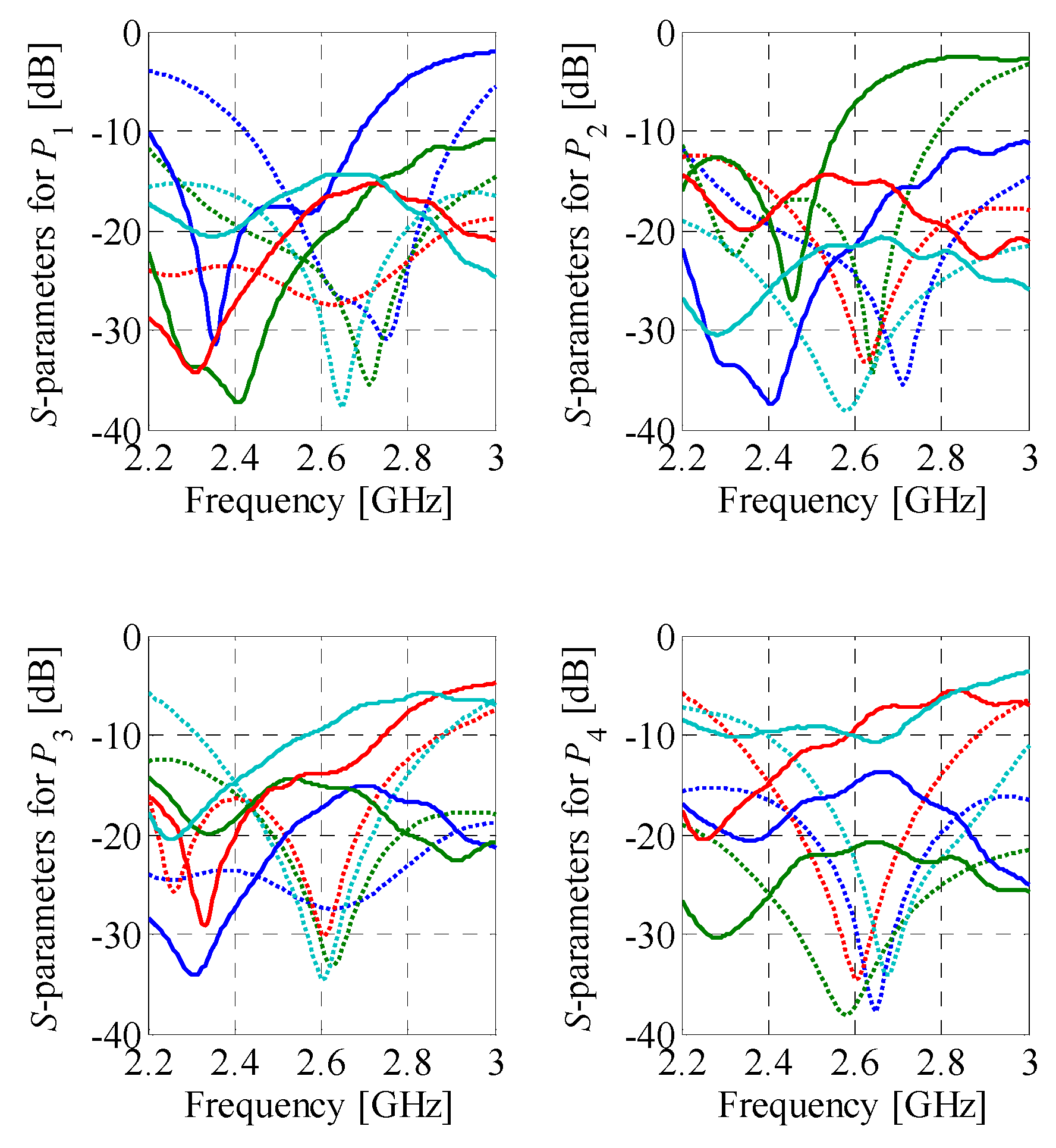

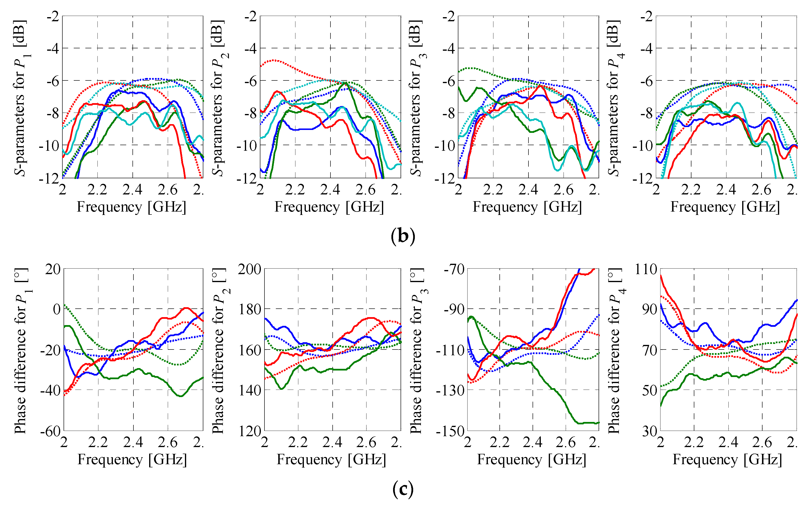
| Excitation | Port P1 | Port P2 | Port P3 | Port P4 |
|---|---|---|---|---|
| RBW (dB) | −21.2 | −15.5 | −17.3 | −16.1 |
| IBW (dB) | 18.4 | 17.6 | 17.6 | 18.1 |
| ΔMBW (dB) | 0.79 | 0.75 | 0.74 | 0.45 |
| ΔMf0 (dB) | 0.51 | 0.45 | 0.41 | 0.14 |
| Target phase (°) | −30 | 150 | −120 | 60 |
| ΔPBW (°) | ±4.9 | ±4.7 | ±4.0 | ±4.3 |
| ΔPf0 (°) | ±1.6 | ±1.3 | ±2.5 | ±2.6 |
| Method | EM Model Type | No. of Model Evaluations | Cost | Total Cost | Performance Figures * | ||||
|---|---|---|---|---|---|---|---|---|---|
| (RBe) | (h) | (RBe) | (h) | RBW (dB) | ΔMf0 (dB) | ΔPf0 (°) | |||
| Direct | RBe | 134 | 134 | 91.6 | 134 | 91.6 | −15.2 | 0.59 | ±3.2 |
| This work | BLC # | 60 | 6.6 | 4.5 | 19.4 | 13.2 | −15.5 | 0.51 | ±2.6 |
| PS # | 120 | 1.8 | 1.2 | ||||||
| RBe | 11 | 11 | 7.5 | ||||||
| Excitation | Port P1 | Port P2 | Port P3 | Port P4 |
|---|---|---|---|---|
| RBW (dB) | −14.9 | −17.1 | −18.3 | −14.5 |
| IBW (dB) | 20.1 | 20.7 | 20.7 | 20.1 |
| ΔMBW (dB) | 0.68 | 0.93 | 0.68 | 0.50 |
| ΔMf0 (dB) | 0.38 | 0.52 | 0.28 | 0.10 |
| Target phase (°) | −30 | 150 | −120 | 60 |
| ΔPBW (°) | ±3.6 | ±4.3 | ±3.8 | ±3.1 |
| ΔPf0 (°) | ±1.3 | ±1.0 | ±1.6 | ±2.1 |
| Excitation * | Port P1 | Port P2 | Port P3 | Port P4 |
|---|---|---|---|---|
| RBW (dB) | −17.6 | −10.8 | −14.5 | −9.1 |
| IBW (dB) | 15.8 | 14.5 | 10.3 | 10.9 |
| ΔMBW (dB) | 2.01 | 2.75 | 3.99 | 1.05 |
| ΔMf0 (dB) | 1.34 | 1.91 | 2.59 | 0.85 |
| Target phase (°) | −30 | 150 | −120 | 60 |
| ΔPBW (°) | ±14.3 | ±9.06 | ±18.4 | ±9.23 |
| ΔPf0 (°) | ±7.48 | ±7.83 | ±10.9 | ±8.79 |
| Designs | Performance Figures * | Size | Relative Size (%) $ | |||||
|---|---|---|---|---|---|---|---|---|
| f0 (GHz) | BW & (%) | ΔMf0 (dB) | Δθ1–4 (°) | ΔPf0 (°) | Dimensions (mm × mm) | Dimensions (λg × λg) | ||
| Conventional [21] | 1.0 | 7.0 | 0.60 | −45, 135, −135, 45 | ±4.0 | 233 × 191 | 1.29 × 1.06 | 100 |
| [23] | 5.8 | 7.3 | 0.45 | −30, 150, −120, 60 | ±3.8 | 71.4 × 119 | 1.89 × 3.15 | 437 |
| [27] | 6.0 | 7.2 | 0.40 | −45, 135, −135, 45 | ±0.9 | 58.9 × 57.9 | 1.96 × 1.93 | 279 |
| [16] | 28 | 3.2 | 4.70 | −45, 135, −135, 45 | ±16 | 16.8 × 14.9 | N/A # | N/A # |
| [28] ! | 1.8 | 5.5 | 2.40 | −45, 135, −135, 45 | ±5.9 | 99.5 × 127 | 0.82 × 1.04 | 62.8 |
| [30] | 1.0 | 5.9 | 2.30 | −45, 135, −135, 45 | ±1.8 | 164 × 121 | 1.00 × 0.74 | 54.1 |
| [29] | 1.0 | N/A | 1.20 | −45, 135, −135, 45 | ±1.0 | 87.8 × 82.4 | 0.49 × 0.46 | 16.3 |
| This work (BM1) | 2.6 | 8.4 | 0.51 | −30, 150, −120, 60 | ±2.6 | 24.0 × 29.0 | 0.34 × 0.42 | 10.5 |
| This work (BM2) | 2.6 | 7.6 | 0.52 | −20, 160, −110, 70 | ±2.1 | 25.9 × 29.6 | 0.37 × 0.42 | 11.6 |
Publisher’s Note: MDPI stays neutral with regard to jurisdictional claims in published maps and institutional affiliations. |
© 2021 by the authors. Licensee MDPI, Basel, Switzerland. This article is an open access article distributed under the terms and conditions of the Creative Commons Attribution (CC BY) license (http://creativecommons.org/licenses/by/4.0/).
Share and Cite
Bekasiewicz, A.; Koziel, S. Low-Cost Unattended Design of Miniaturized 4 × 4 Butler Matrices with Nonstandard Phase Differences. Sensors 2021, 21, 851. https://doi.org/10.3390/s21030851
Bekasiewicz A, Koziel S. Low-Cost Unattended Design of Miniaturized 4 × 4 Butler Matrices with Nonstandard Phase Differences. Sensors. 2021; 21(3):851. https://doi.org/10.3390/s21030851
Chicago/Turabian StyleBekasiewicz, Adrian, and Slawomir Koziel. 2021. "Low-Cost Unattended Design of Miniaturized 4 × 4 Butler Matrices with Nonstandard Phase Differences" Sensors 21, no. 3: 851. https://doi.org/10.3390/s21030851
APA StyleBekasiewicz, A., & Koziel, S. (2021). Low-Cost Unattended Design of Miniaturized 4 × 4 Butler Matrices with Nonstandard Phase Differences. Sensors, 21(3), 851. https://doi.org/10.3390/s21030851


