Machining Safety in Dry Rough Milling of Casting Magnesium Alloy AZ91D Using Carbide End Mills with Different Geometries
Abstract
1. Introduction
2. Materials, Methodology, Aims, and Scope of the Study
3. Results
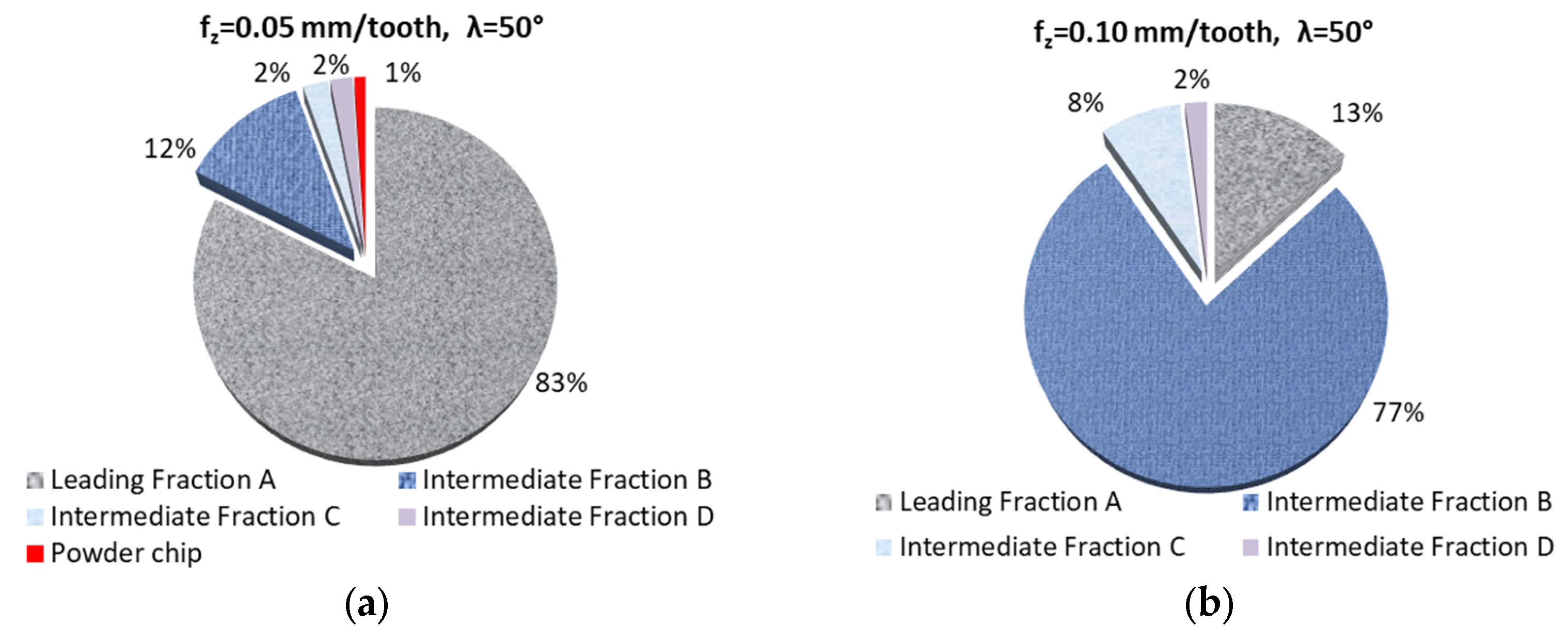
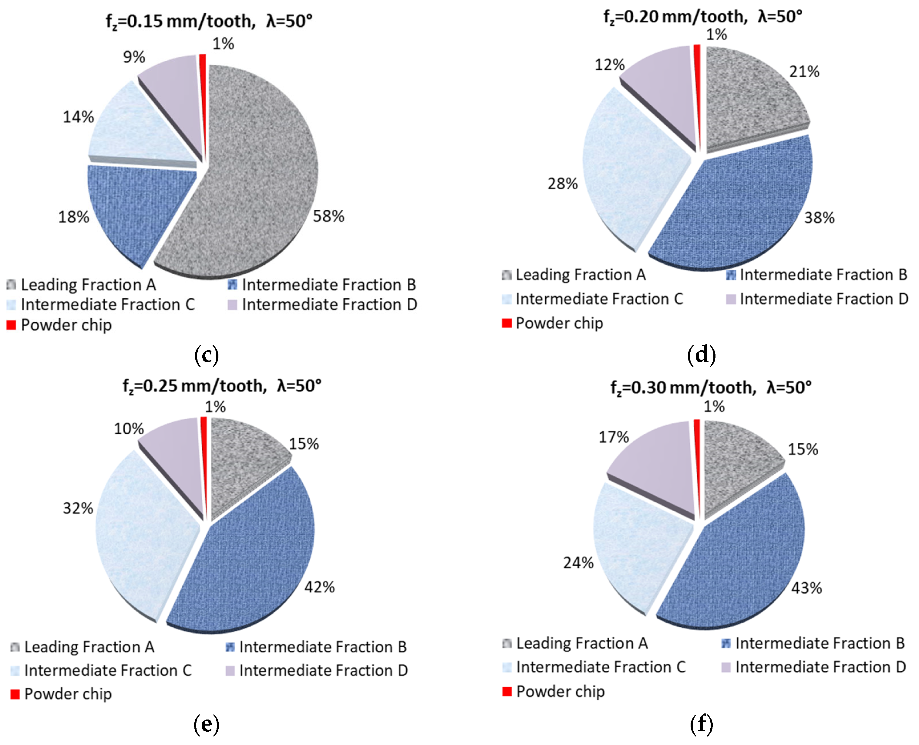
3.1. Fractions and Percentage Share of Chips
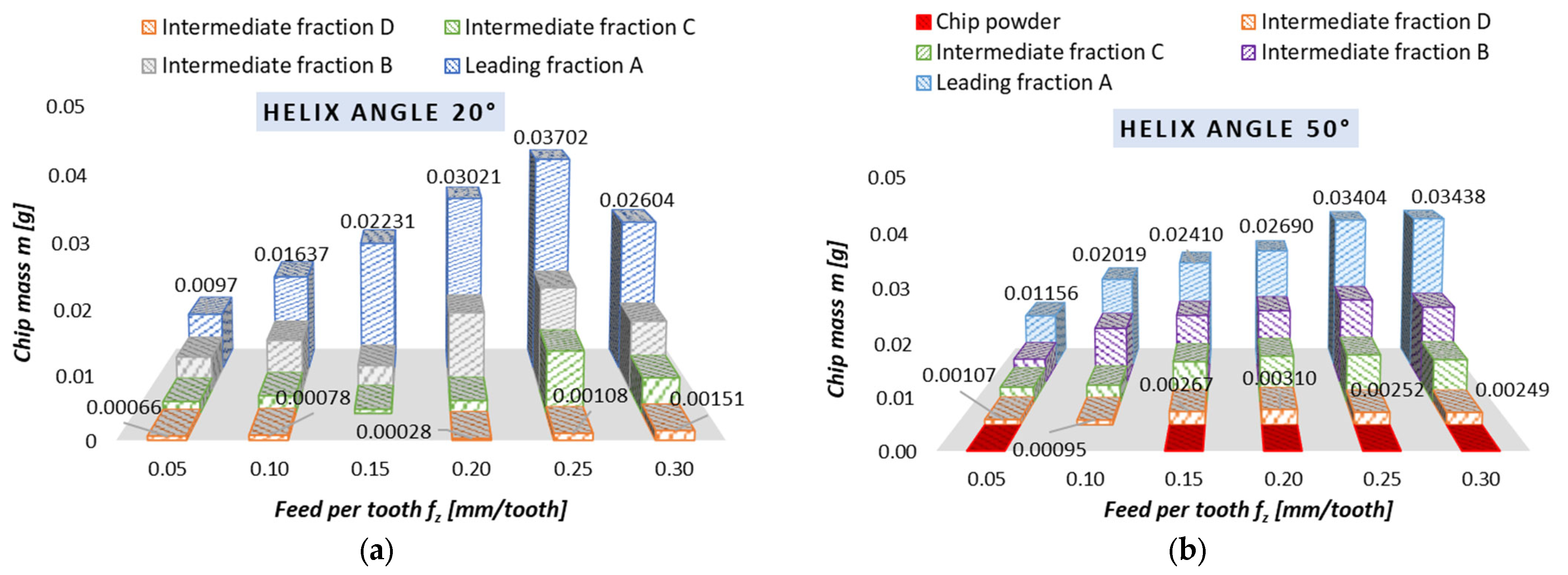
3.2. Chips Mass
- -
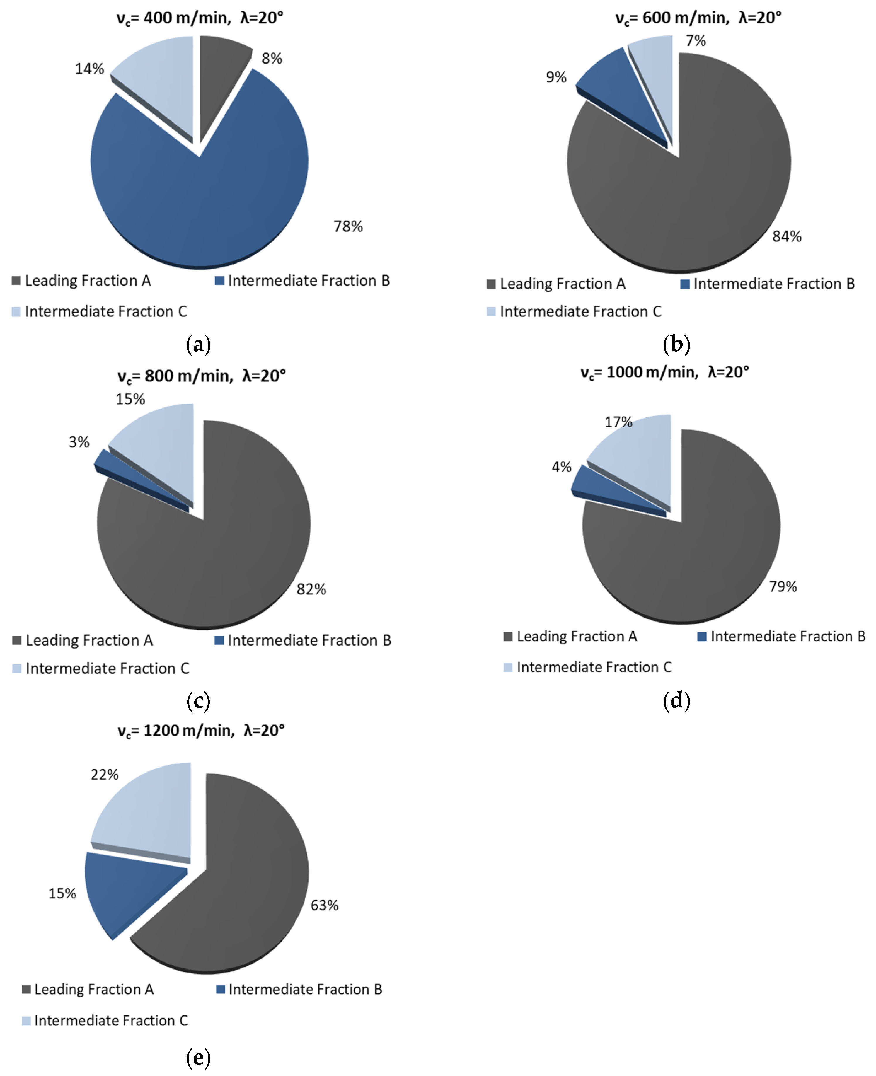
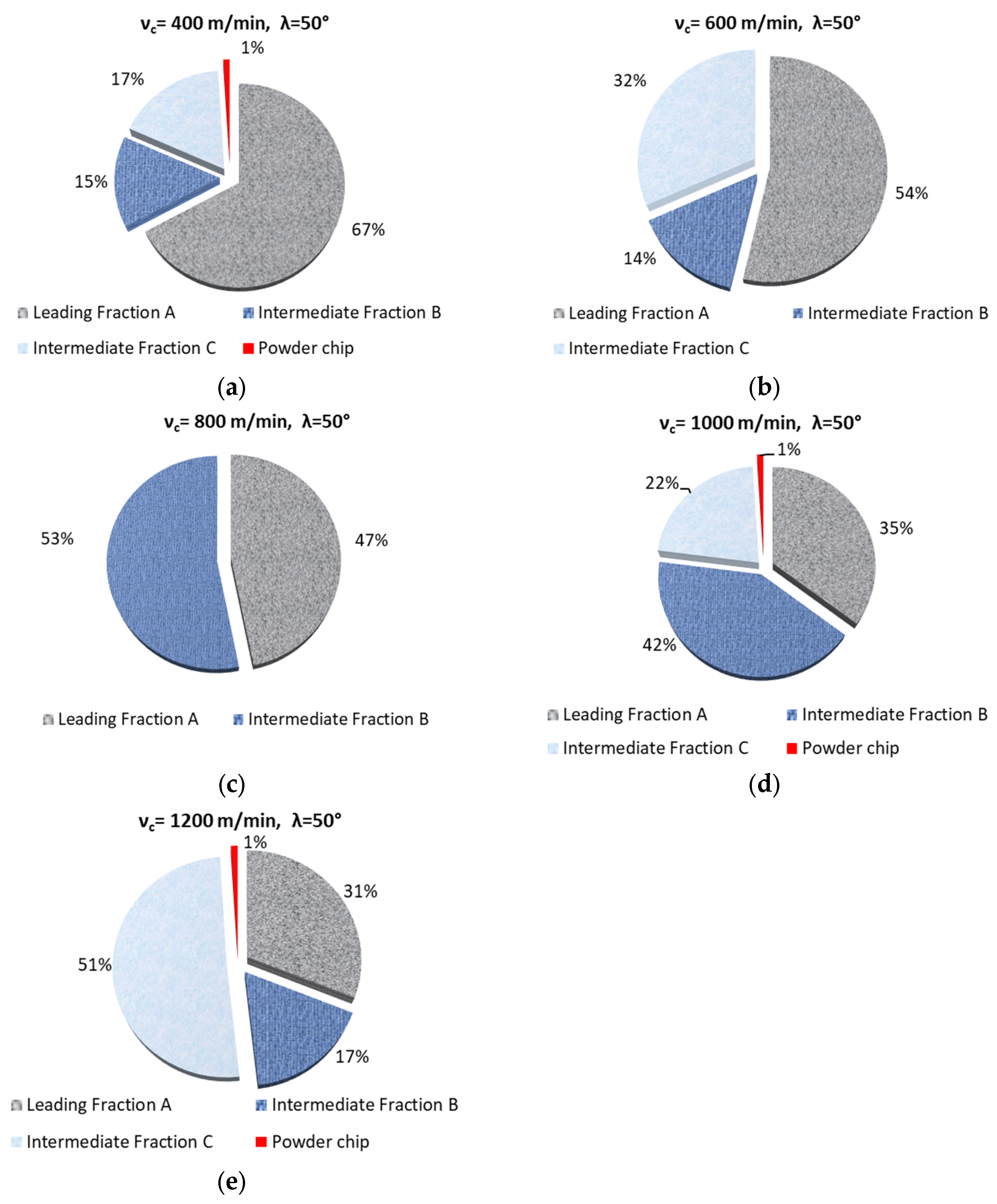
- there are 2 chip fractions (for a helix angle of 50° and vc of 800 m/min),
- -
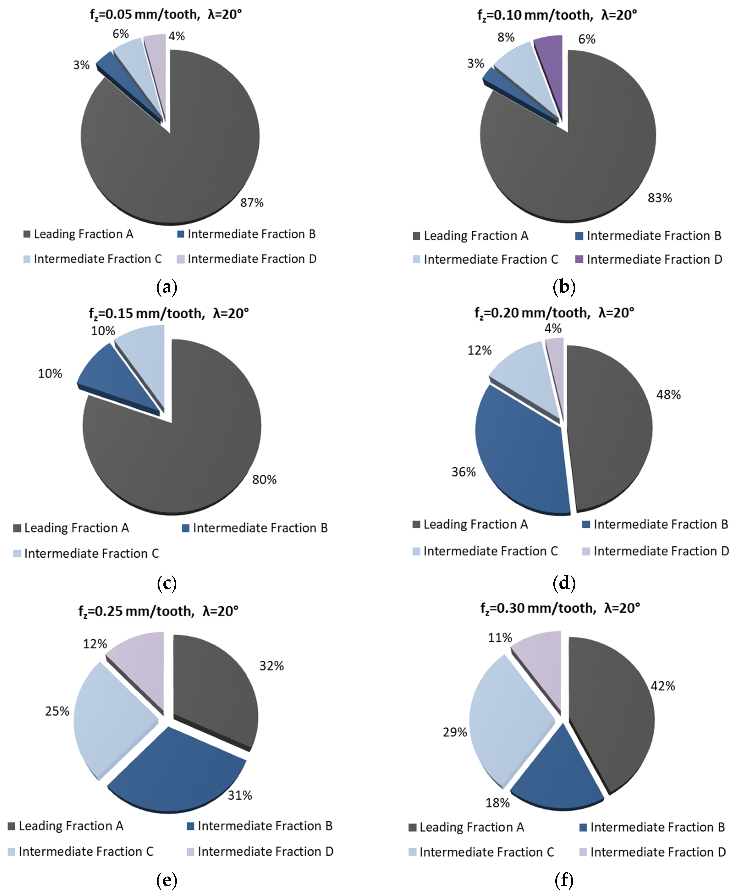
- there are 3 chip fractions (for a helix angle of 20° and the entire tested range of vc, for fz of 0.15 mm/tooth, for a helix angle of 50° and vc of 600 m/min),
- -
- there are 4 fractions of chips (for a helix angle of 50° and fz of 0.10 mm/tooth).
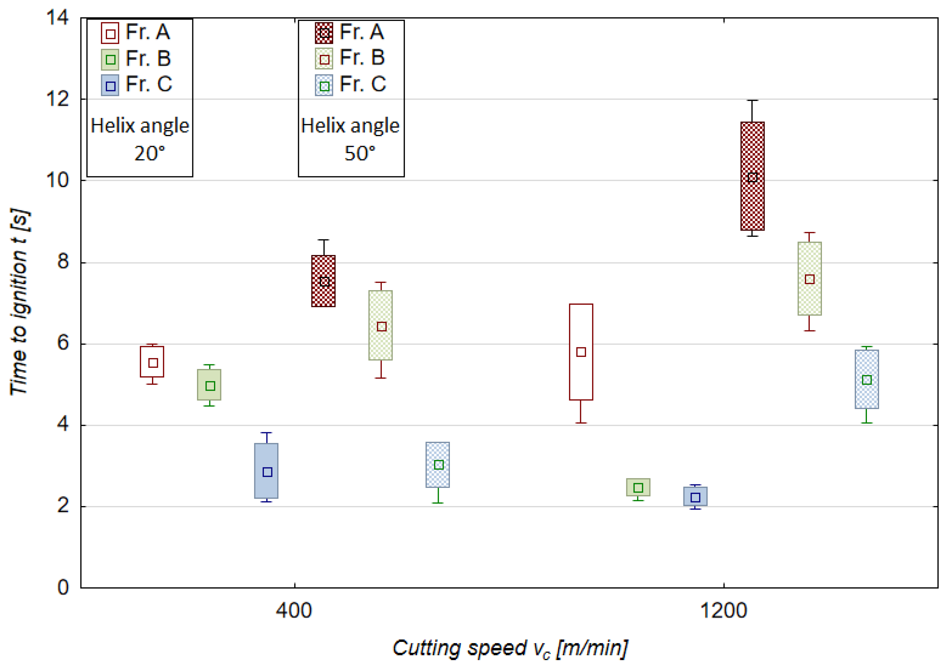
3.3. Time to Ignition, Temperature of Ignition
3.4. Chip Morphology, Chip Ignition Stages
4. Discussion
5. Conclusions
- -
- It is possible to implement safe, effective, as well as reliable dry milling of magnesium alloys, and therefore ensure safe maintenance of machine tools without a potential risk of damaging their components.
- -
- The best and most preferred machining conditions are those which generate only two or three chip fractions (e.g., full range vc and fz for 20° helix angle tool).
- -
- -
- The use of the 20° helix angle tool produces no chip powder, a product which is considered the most harmful and potentially dangerous chip fraction; this tool should therefore be the first choice for rough machining of magnesium alloys.
- -
- The most advantageous machining areas are those where the A fraction constitutes about 50% of the share in all chip fractions; this situation occurs for the entire vc range (without vc equal to 400 m/min) for λs = 20° and vc 400–800 m/min for λs = 50°; the range 0.05–0.20 mm/tooth for λs = 20° and for 0.05 and 0.15 mm/tooth for λs = 50°.
- -
- The unit mass of chips is an important indicator for estimating machining safety in terms of ignition susceptibility of individual chip fractions; unit chip mass of fraction A is within the following ranges: for vc and λs = 20—from 0.02260 to 0.04466 g; for vc and λs = 50°—from 0.01961 to 0.02759 g; for fz and λs = 20°—from 0.00970 to 0.03702 g; for fz and λs = 50°—from 0.01156 to 0.03438 g.
- -
- For the 50° helix angle tool, it was observed that the use of higher machining parameters led to a higher unit mass of leading fraction A (a similar trend was observed for the 20° helix angle tool and the feed of 0.25 mm/tooth).
- -
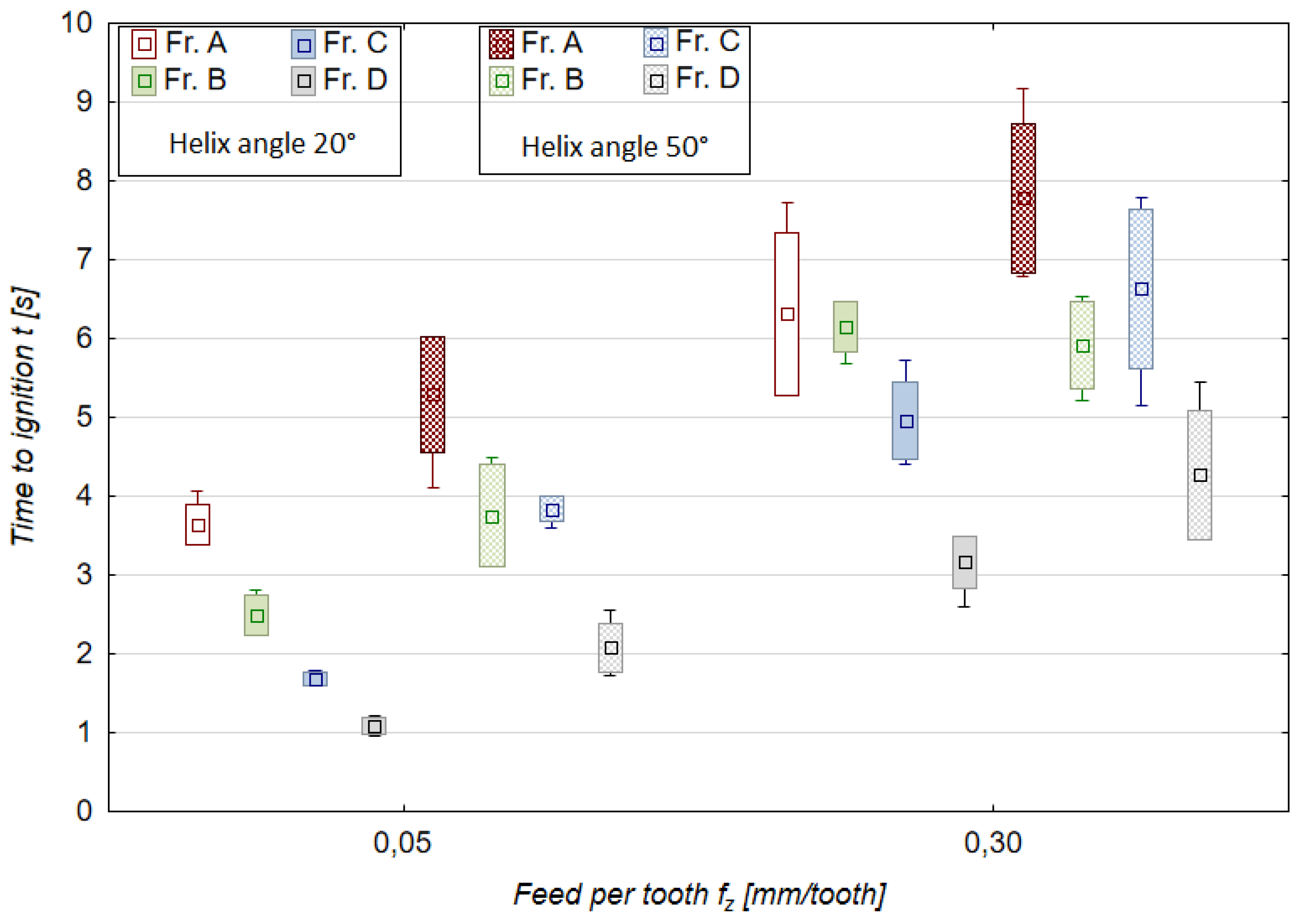
- The longest time to chip ignition was observed for leading fraction A, and it should be emphasized that the ignition of intermediate fraction D was not immediate (the chips ignited after approx. 1–3.5 s for the variable feed per tooth and after 2–4 s for the variable cutting speed), which is an important finding regarding ignition susceptibility and sudden ignition hazard when carrying out machining operations.
- -
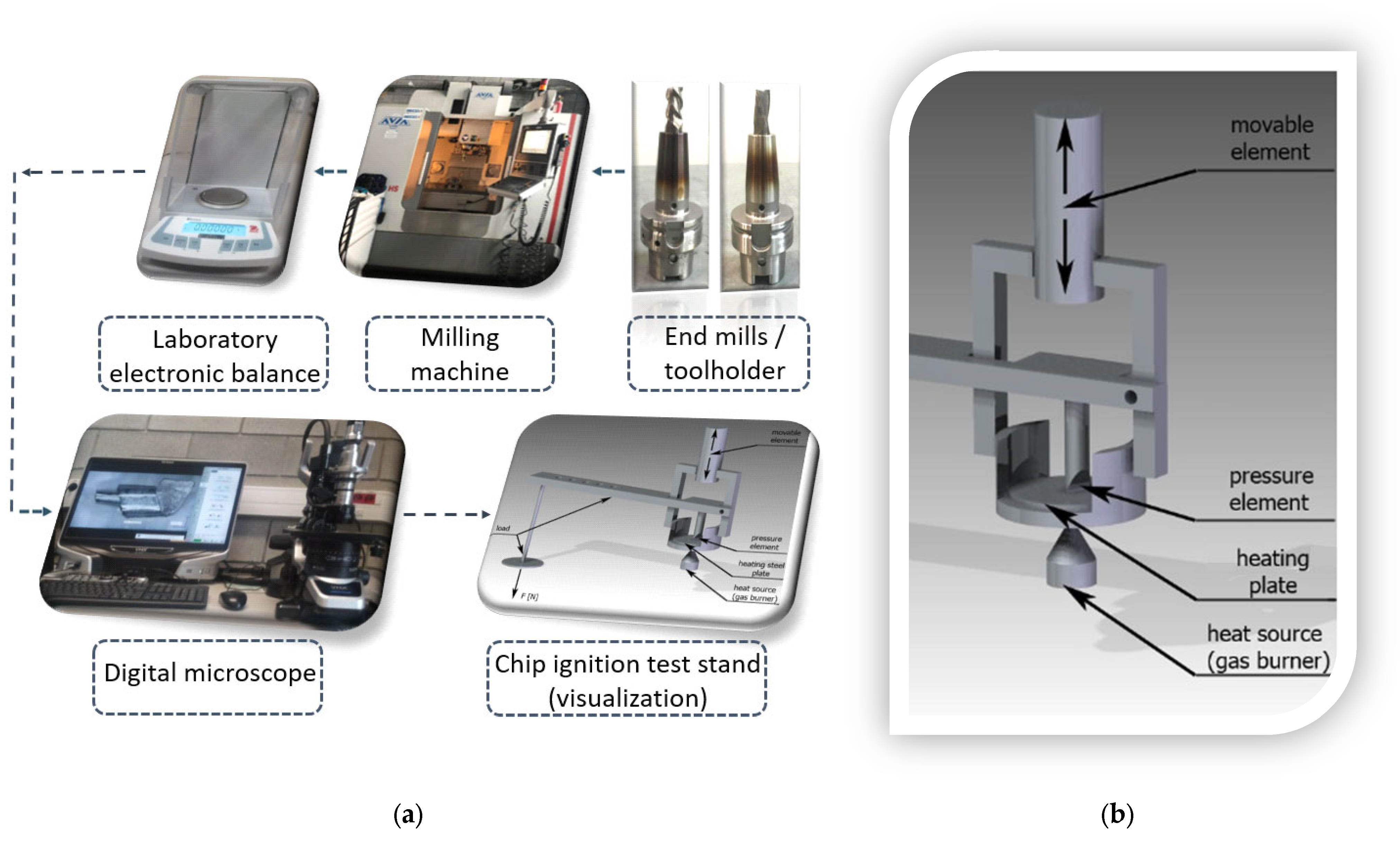
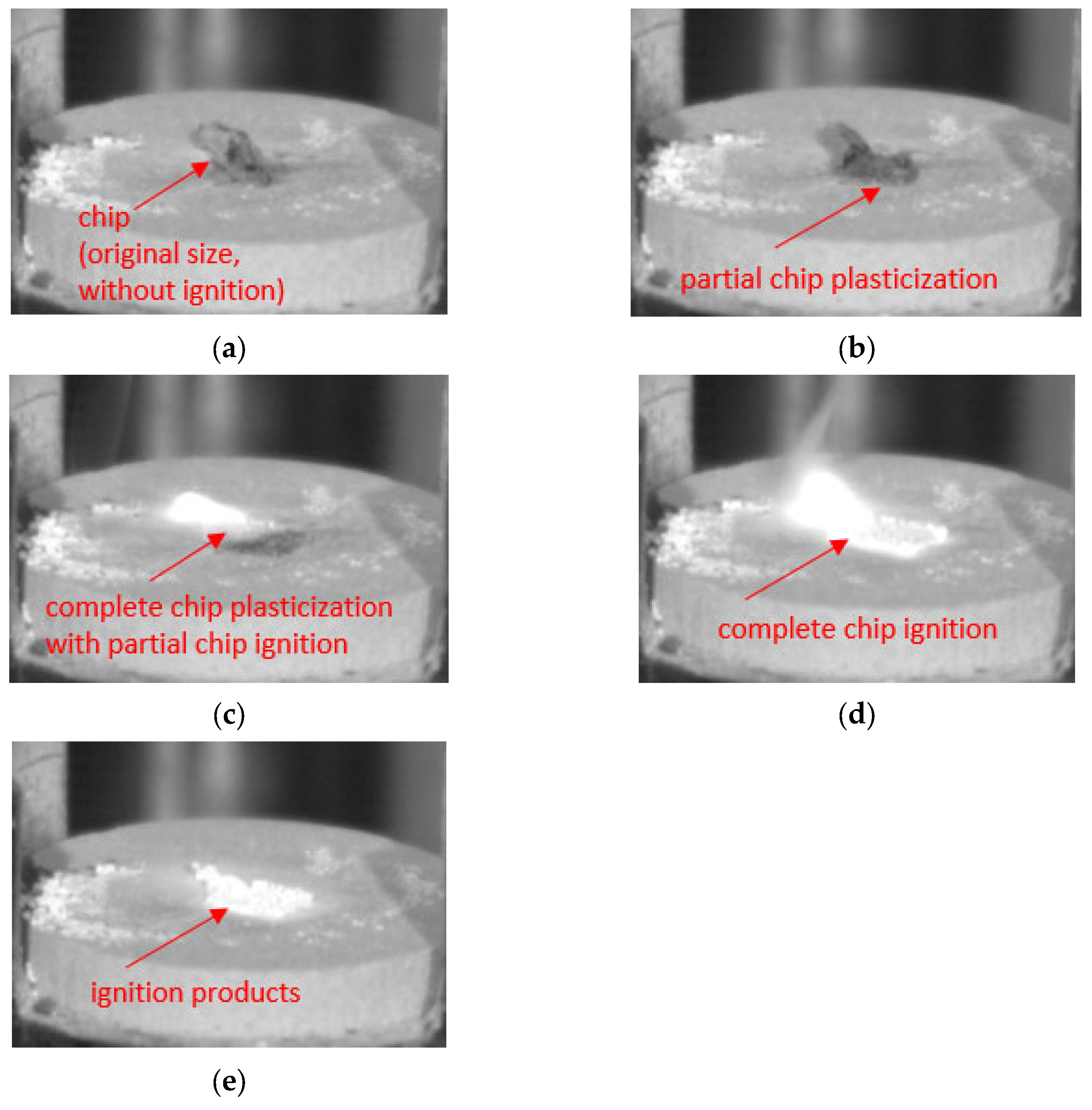
- Both time to ignition as well as ignition temperature (determined outside of the milling machine, at a specially designed and constructed test stand) are important safety indicators, as they make it possible to estimate machining conditions that are considered safe working areas for a given machine tool.
- -
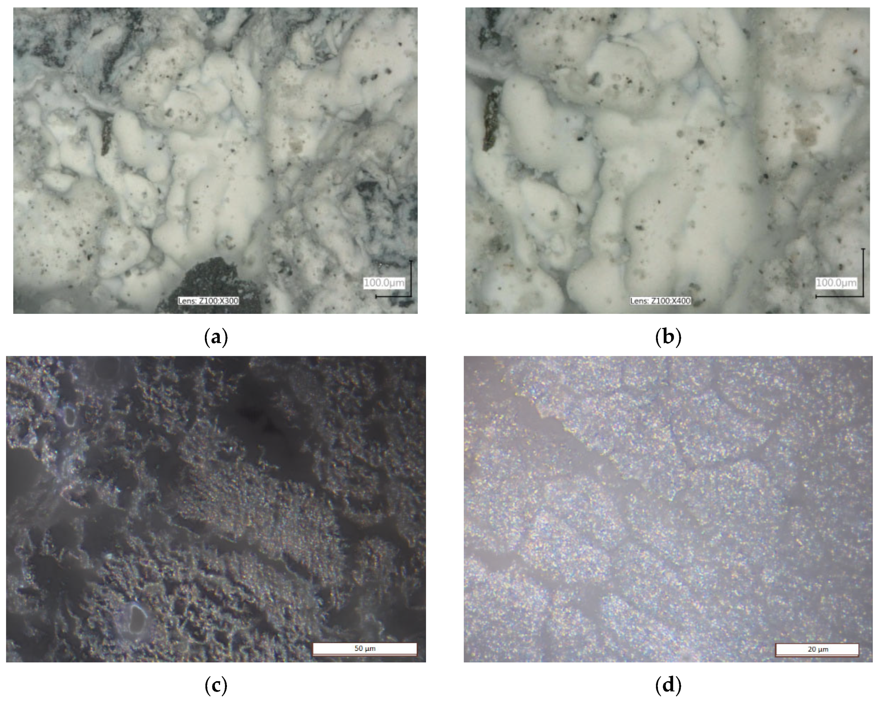
- The AZ91D alloy chip surfaces (obtained by SEM and metallographic examination) were free from ignition or intense oxidation products and had clearly outlined edges; hence, under the presented machining conditions, no risk of chip ignition was observed during machining.
Funding
Institutional Review Board Statement
Informed Consent Statement
Data Availability Statement
Conflicts of Interest
Abbreviations
| λs | Helix angle |
| vc | Cutting speed |
| fz | Feed per tooth |
| ap | Axial depth of cut |
| ae | Radial depth of cut |
| z | Number of blade, tooth |
| HSM | High speed machining |
| HSC | High speed cutting |
| HPC | High performance cutting |
| SEM | Scanning electron microscopy |
| Tav | Average temperature |
| Tmax | Maximum temperature |
| Fr. A | Chip fraction (leading A) |
| Fr. B | Chip fraction (intermediate B) |
| Fr. C | Chip fraction (intermediate C) |
| Fr. D | Chip fraction (intermediate D) |
References
- Semotiuk, L. An analysis of the operational characteristics of innovative tool structures used in high speed rough milling processes. Eksploat. I Niezawodn.-Maint. Reliab. 2009, 1, 46–53. [Google Scholar]
- Karimi, M.; Nosouhi, R. An experimental investigation on temperature distribution in high-speed milling of AZ91C magnesium alloy. AUT J. Mech. Eng. 2021, 5, 419–426. [Google Scholar] [CrossRef]
- Kryzhanivskyy, V.; Saoubi, R.M.; Ståhl, J.E.; Bushlya, V. Tool–chip thermal conductance coefficient and heat flux in machining: Theory, model and experiment. Int. J. Mach. Tools Manuf. 2019, 147, 103468. [Google Scholar] [CrossRef]
- Karaguzel, U.; Bakkal, M.; Budak, E. Modeling and Measurement of Cutting Temperatures in Milling. Procedia CIRP 2016, 46, 173–176. [Google Scholar] [CrossRef]
- Liu, C.; Liu, B.; Zhou, Y.; He, Y.; Chi, D.; Gao, X.; Liu, Q. A Real-Time Cutting Temperature Monitoring of Tool in Peripheral Milling Based on Wireless Transmission. Int. J. Therm. Sci. 2023, 186, 108084. [Google Scholar] [CrossRef]
- Ravi Kumar, N.V.; Blandin, J.J.; Suery, M.; Grosjean, E. Effect of alloying elements on the ignition resistance of magnesium alloys. Scr. Mater. 2003, 49, 225–230. [Google Scholar] [CrossRef]
- Zhou, H.; Li, W.; Wang, M.X.; Zhao, Y. Study on ignition proof AZ91D magnesium alloy chips with cerium addition. J. Rare Earth 2005, 23, 466–469. [Google Scholar]
- Lin, P.Y.; Zhou, H.; Li, W.; Li, W.P.; Sun, N.; Yang, R. Interactive effect of cerium and aluminum on the ignition point and the oxidation resistance of magnesium alloy. Corros. Sci. 2008, 50, 2669–2675. [Google Scholar] [CrossRef]
- Liu, M.; Shih, D.S.; Parish, C.; Atrens, A. The ignition temperature of Mg alloys WE43, AZ31 and AZ91. Corros. Sci. 2012, 54, 139–142. [Google Scholar] [CrossRef]
- Zagórski, I. Safety in Rough Milling of Magnesium Alloys Using Tools with Variable Cutting Edge Geometry. Adv. Sci. Technol. Res. J. 2023, 17, 181–191. [Google Scholar] [CrossRef]
- Habrat, D.; Stadnicka, D.; Habrat, W. Analysis of the legal risk in the scientific experiment of the machining of magnesium alloys. In Advances in Manufacturing Engineering and Materials; Hloch, S., Klichova, D., Krolczyk, G.M., Chattopadhyaya, S., Ruppenthalova, L., Eds.; Lecture Notes in Mechanical Engineering; Springer: Cham, Switzerland, 2019; pp. 421–430. [Google Scholar] [CrossRef]
- Gziut, O.; Kuczmaszewski, J.; Zagórski, I. Analysis of chip fragmentation in AZ91HP alloy milling with respect to reducing the risk of chip. Eksploat. I Niezawodn.-Maint. Reliab. 2016, 18, 73–79. [Google Scholar] [CrossRef]
- Gziut, O.; Kuczmaszewski, J.; Zagórski, I. Impact of depth of cut on chip formation in AZ91HP magnesium alloy milling with tools of varying cutting edge geometry. Adv. Sci. Technol. Res. J. 2015, 9, 49–56. [Google Scholar] [CrossRef] [PubMed][Green Version]
- Kuczmaszewski, J.; Zagórski, I.; Gziut, O.; Legutko, S.; Krolczyk, G.M. Chip fragmentation in the milling of AZ91HP magnesium alloy. Stroj. Vestn.-J. Mech. Eng. 2017, 63, 628–642. [Google Scholar] [CrossRef]
- Legutko, S. Development trends in machines operation maintenance. Eksploat. I Niezawodn.-Maint. Reliab. 2009, 2, 8–16. [Google Scholar]
- Sahoo, S.K.; Sahoo, B.N.; Panigrahi, S.K. Investigation into machining performance of microstructurally engineered in-situ particle reinforced magnesium matrix composite. J. Magnes. Alloys 2023, 11, 916–935. [Google Scholar] [CrossRef]
- Skoczylas, A.; Kłonica, M. Selected Properties of the Surface Layer of C45 Steel Samples after Slide Burnishing. Materials 2023, 16, 6513. [Google Scholar] [CrossRef]
- Skoczylas, A.; Zaleski, K.; Zaleski, R.; Gorgol, M. Analysis of surface properties of nickel alloy elements exposed to impulse shot peening with the use of positron annihilation. Materials 2021, 14, 7328. [Google Scholar] [CrossRef]
- Kuczmaszewski, J.; Pieśko, P. Wear of milling cutters resulting from high silicon aluminium alloy cast AlSi21CuNi machining. Eksploat. I Niezawodn.-Maint. Reliab. 2014, 16, 37–41. [Google Scholar]
- Zgórniak, P.; Grdulska, A. Investigation of temperature distribution during milling process of AZ91HP magnesium alloys. Mech. Mech. Eng. 2012, 16, 33–40. [Google Scholar]
- Zgórniak, P.; Stachurski, W.; Ostrowski, D. Application of thermographic measurements for the determination of the impact of selected cutting parameters on the temperature in the workpiece during milling process. Stroj. Vestn.-J. Mech. Eng. 2016, 62, 657–664. [Google Scholar] [CrossRef][Green Version]
- Cichosz, P.; Karolczak, P.; Waszczuk, K. Review of Cutting Temperature Measurement Methods. Materials 2023, 16, 6365. [Google Scholar] [CrossRef] [PubMed]
- Fang, F.Z.; Lee, L.C.; Liu, X.D. Mean flank temperature measurement in high speed dry cutting. J. Mater. Process. Technol. 2005, 167, 119–123. [Google Scholar] [CrossRef]
- Hou, J.; Zhao, N.; Zhu, S. Influence of Cutting Speed on Flank Temperature during Face Milling of Magnesium Alloy. Mater. Manuf. Process. 2011, 26, 1059–1063. [Google Scholar] [CrossRef]
- Le Coz, G.; Marinescu, M.; Devillez, A.; Dudzinski, D.; Velnom, L. Measuring temperature of rotating cutting tools: Application to MQL drilling and dry milling of aerospace alloys. Appl. Therm. Eng. 2012, 36, 434–441. [Google Scholar] [CrossRef]
- de Oliveira Moreira, M.; Abrão, A.M.; Ferreira, R.A.; Porto, M.P. Temperature Monitoring of Milling Processes Using a Directional-Spectral Thermal Radiation Heat Transfer Formulation and Thermography. Int. J. Heat Mass Transf. 2021, 171, 121051. [Google Scholar] [CrossRef]
- Masoudi, S.; Gholami, M.A.; Lariche, M.J.; Vafadar, A. Infrared temperature measurement and increasing infrared measurement accuracy in the context of machining process. Adv. Prod. Eng. Manag. 2017, 12, 353–362. [Google Scholar] [CrossRef]
- Guimarães, B.; Rosas, J.; Fernandes, C.M.; Figueiredo, D.; Lopes, H.; Paiva, O.C.; Silva, F.S.; Miranda, G. Real-Time Cutting Temperature Measurement in Turning of AISI 1045 Steel through an Embedded Thermocouple—A Comparative Study with Infrared Thermography. J. Manuf. Mater. Process. 2023, 7, 50. [Google Scholar] [CrossRef]
- Li, T.; Long, H.; Shi, T.; Yang, J.; Duan, J. Cutting temperature measurement using a novel near-infrared two-color pyrometer under dry and wet cutting of Ti-6Al-4V alloy. J. Mater. Process. Technol. 2022, 309, 117751. [Google Scholar] [CrossRef]
- Hou, J.; Zhou, W.; Zhao, N. Methods for prevention of ignition during machining of magnesium alloys. Key Eng. Mater. 2010, 447–448, 150–154. [Google Scholar] [CrossRef]
- Zhao, N.; Hou, J.; Zhu, S. Chip ignition in research on high-speed face milling AM50A magnesium alloy. In Proceedings of the 2nd International Conference on Mechanic Automation and Control Engineering, Inner Mongolia, China, 15–17 July 2011. [Google Scholar] [CrossRef]
- Han, D.; Zhang, J.; Huang, J.; Lian, Y.; He, G. A review on ignition mechanisms and characteristics of magnesium alloys. J. Magnes. Alloys 2020, 8, 329–344. [Google Scholar] [CrossRef]
- Akyuz, B. Machinability of magnesium and its alloys. Online J. Sci. Technol. 2011, 1, 31–38. [Google Scholar]
- Guo, Y.B.; Salahshoor, M. Process mechanics and surface integrity by high-speed dry milling of biodegradable magnesium–calcium implant alloys. CIRP Ann.-Manuf. Technol. 2010, 59, 151–154. [Google Scholar] [CrossRef]
- Guo, Y.; Liu, Z. Sustainable High Speed Dry Cutting of Magnesium Alloys. Mater. Sci. Forum Online 2012, 723, 3–13. [Google Scholar] [CrossRef]
- PN-ISO 3685:1996; Tool-Life Testing with Single-Point Turning Tools. SMC, Sektor Maszyn i Inżynierii: Pass, Poland, 1996. (In Polish)
- ISO 3685:1993; Tool-Life Testing with Single-Point Turning Tools. International Organization for Standardization: Geneva, Switzerland, 1993.



| Machining Conditions | Research Object, Machinability Indicators | Reference |
|---|---|---|
| Dry Rough Down End-Milling (different helix angles): ap = 0.5–6.0 mm, fz = 0.15 mm/tooth, vc = 800 m/min, ae = 14 mm | Fractions of chips and their metallographic images, chip mass, percentage share of chip fractions, time to ignition, ignition temperature, stages preceding chip ignition | [10] |
| Dry Rough Down End-Milling (different rake angles): ap = 0.5–3.0 mm, fz = 0.05–0.30 mm/tooth, vc = 400–1200 m/min, ae = 14 mm | Fractions of chips and their metallographic images, chip mass, dimensions | [12] |
| Dry Rough Down End-Milling (different rake angles): ap = 0.5–3.0 mm, fz = 0.05 and 0.15 mm/tooth, vc = 800 m/min, ae = 14 mm | Fractions of chips and their metallographic images | [13] |
| Dry Rough Down End-Milling (different rake angles): ap = 6.0 mm, fz = 0.05–0.30 mm/tooth, vc = 400–1200 m/min, ae = 14 mm | Fractions of chips and their metallographic images, chip mass, percentage share of chip fractions, dimensions of chips, share of individual fractions in the total chip population | [14] |
| Type of Chip Fraction | Cutting Speed vc [m/min] | ||||
|---|---|---|---|---|---|
| 400 | 600 | 800 | 1000 | 1200 | |
| Leading fraction A |  | 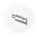 | 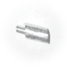 | 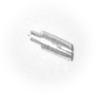 |  |
| Intermediate fraction B |  |  | 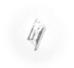 | 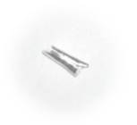 |  |
| Intermediate fraction C |  |  | 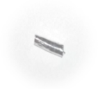 | 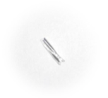 | 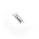 |
| Intermediate fractions D | None | None | None | None | None |
| Chip powder | None | None | None | None | None |
| Type of Chip Fraction | Cutting Speed vc [m/min] | ||||
|---|---|---|---|---|---|
| 400 | 600 | 800 | 1000 | 1200 | |
| Leading fraction A |  | 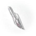 |  | 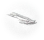 | 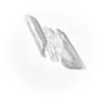 |
| Intermediate fraction B | 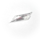 |  | 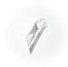 |  | 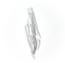 |
| Intermediate fraction C |  |  | None | 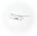 | 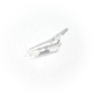 |
| Intermediate fraction D | None | None | None | None | None |
| Powder chip | 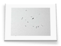 | None | None | 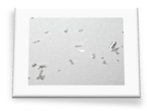 |  |
| Type of Chip Fraction | Feed per Tooth fz [mm/tooth] | |||||
|---|---|---|---|---|---|---|
| 0.05 | 0.10 | 0.15 | 0.20 | 0.25 | 0.30 | |
| Leading fraction A |  |  |  | 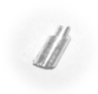 |  |  |
| Intermediate fraction B |  |  |  | 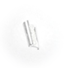 | 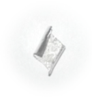 |  |
| Intermediate fraction C | 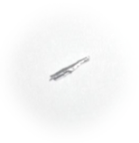 | 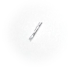 |  |  |  | 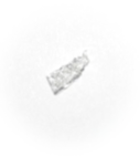 |
| Intermediate fraction D |  |  | None | 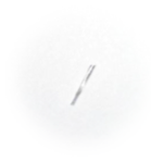 |  | 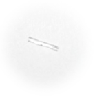 |
| Powder chip | None | None | None | None | None | None |
| Type of Chip Fraction | Feed per Tooth fz [mm/tooth] | |||||
|---|---|---|---|---|---|---|
| 0.05 | 0.10 | 0.15 | 0.20 | 0.25 | 0.30 | |
| Leading fraction A | 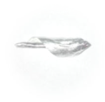 | 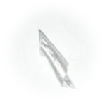 | 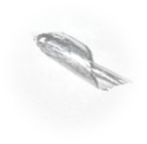 | 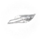 | 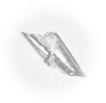 | 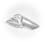 |
| Intermediate fraction B | 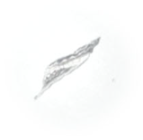 |  |  |  | 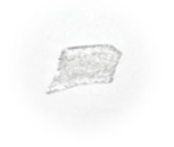 | 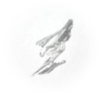 |
| Intermediate fraction C | 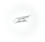 | 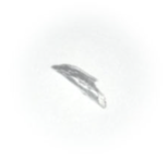 | 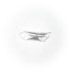 |  |  | 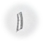 |
| Intermediate fraction D |  | 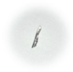 | 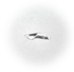 | 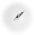 | 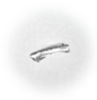 |  |
| Powder chip |  | None |  |  |  |  |
Disclaimer/Publisher’s Note: The statements, opinions and data contained in all publications are solely those of the individual author(s) and contributor(s) and not of MDPI and/or the editor(s). MDPI and/or the editor(s) disclaim responsibility for any injury to people or property resulting from any ideas, methods, instructions or products referred to in the content. |
© 2025 by the author. Licensee MDPI, Basel, Switzerland. This article is an open access article distributed under the terms and conditions of the Creative Commons Attribution (CC BY) license (https://creativecommons.org/licenses/by/4.0/).
Share and Cite
Zagórski, I. Machining Safety in Dry Rough Milling of Casting Magnesium Alloy AZ91D Using Carbide End Mills with Different Geometries. Materials 2025, 18, 1104. https://doi.org/10.3390/ma18051104
Zagórski I. Machining Safety in Dry Rough Milling of Casting Magnesium Alloy AZ91D Using Carbide End Mills with Different Geometries. Materials. 2025; 18(5):1104. https://doi.org/10.3390/ma18051104
Chicago/Turabian StyleZagórski, Ireneusz. 2025. "Machining Safety in Dry Rough Milling of Casting Magnesium Alloy AZ91D Using Carbide End Mills with Different Geometries" Materials 18, no. 5: 1104. https://doi.org/10.3390/ma18051104
APA StyleZagórski, I. (2025). Machining Safety in Dry Rough Milling of Casting Magnesium Alloy AZ91D Using Carbide End Mills with Different Geometries. Materials, 18(5), 1104. https://doi.org/10.3390/ma18051104


