

Investigation of Distortion, Porosity and Residual Stresses in Internal Channels Fabricated in Maraging 300 Steel by Laser Powder Bed Fusion

 ,
,  , , , and
Abstract
1. Introduction
2. Materials and Methods
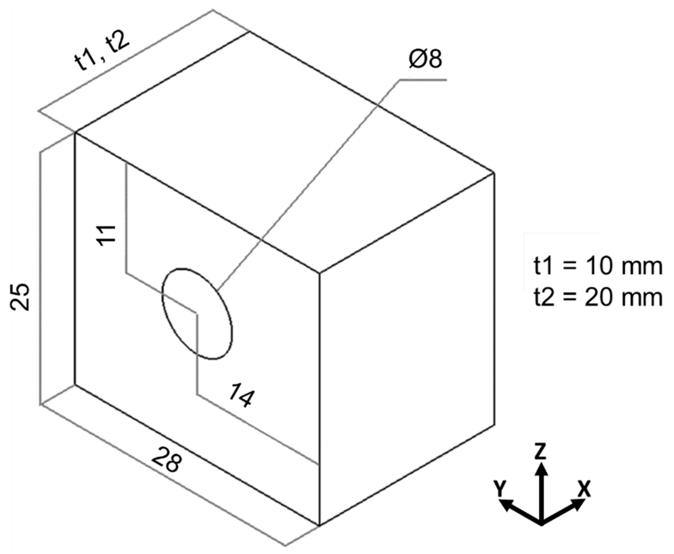
2.1. Specimen Design
2.2. Material
2.3. LPBF Processing
2.4. Characterization
2.4.1. Three-Dimensional Scanning
2.4.2. Density Measurement
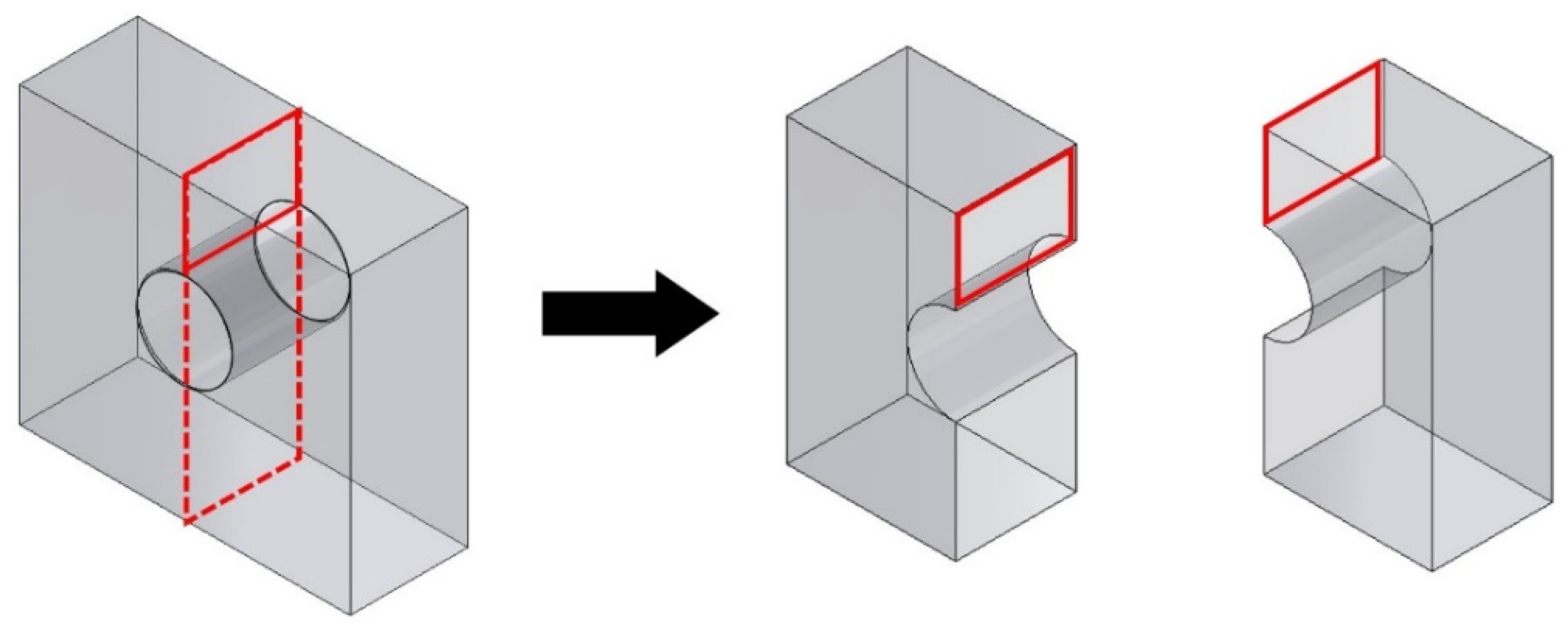
2.4.3. Computed Tomography
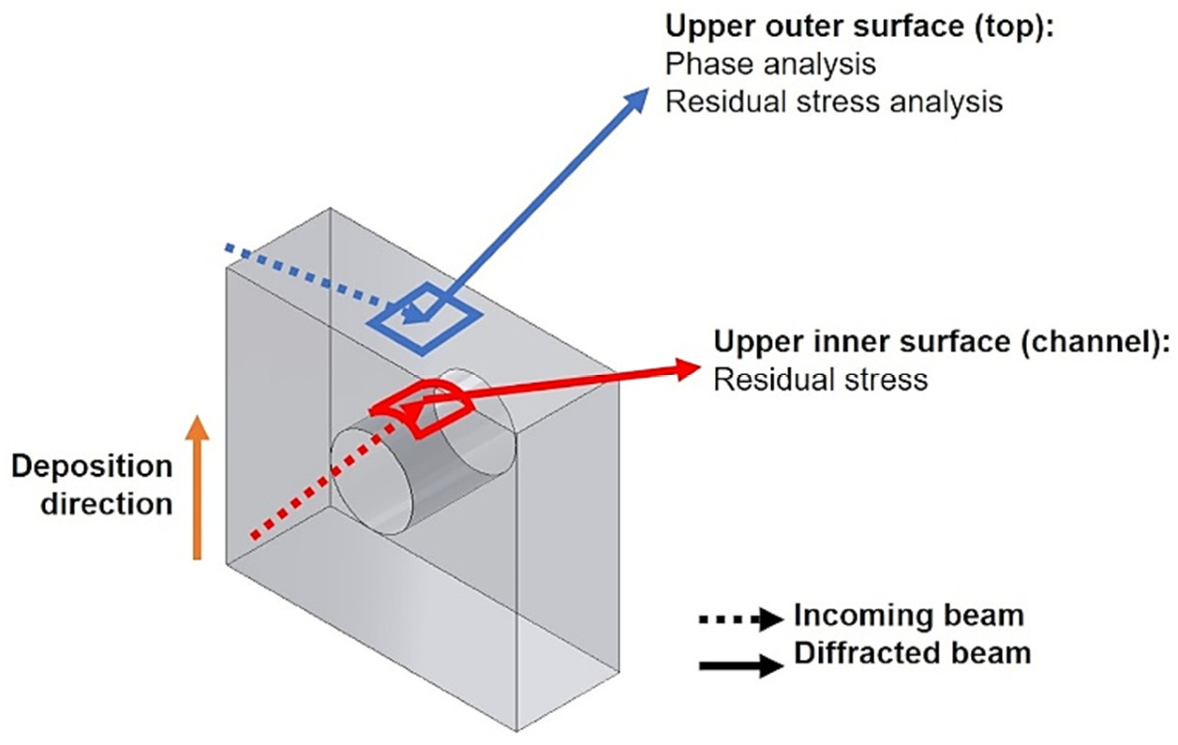
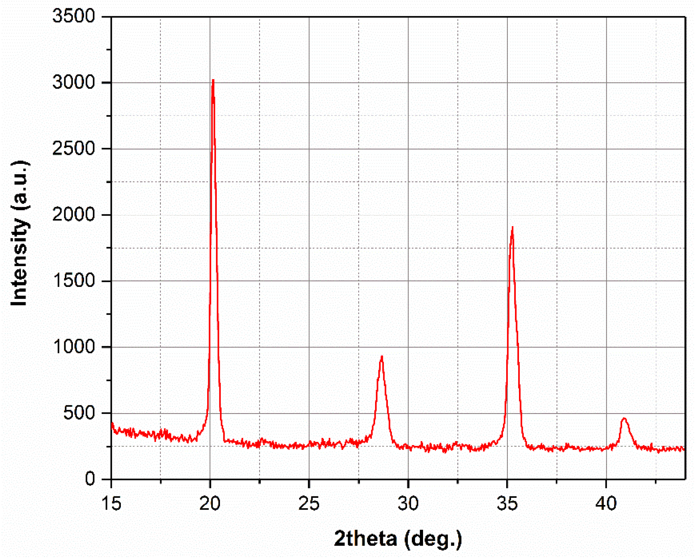
2.4.4. X-Ray Diffraction
2.4.5. Microstructural Analysis
3. Results and Discussion
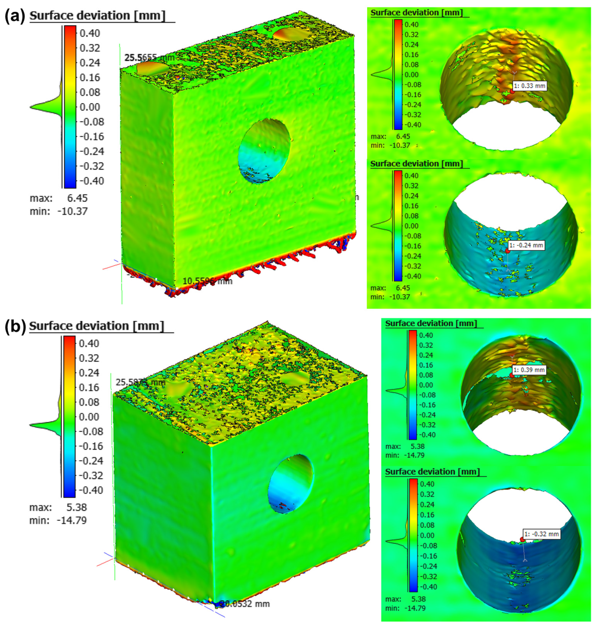
3.1. Distortions
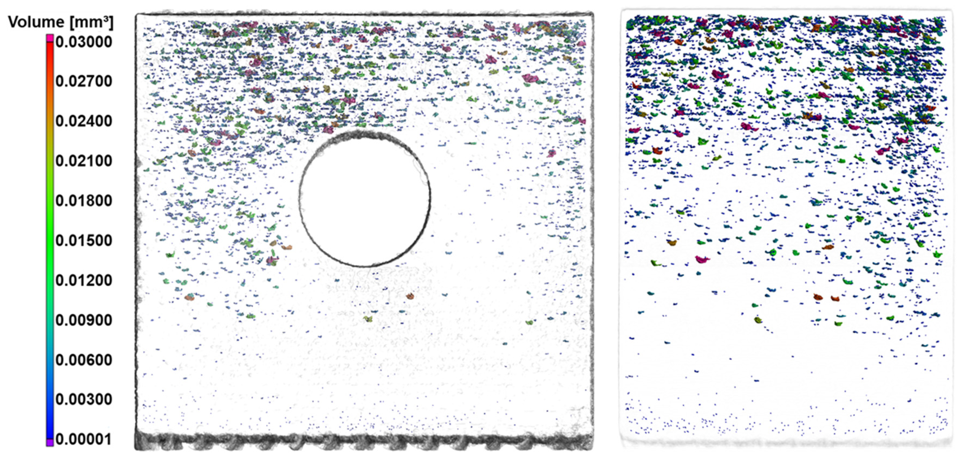
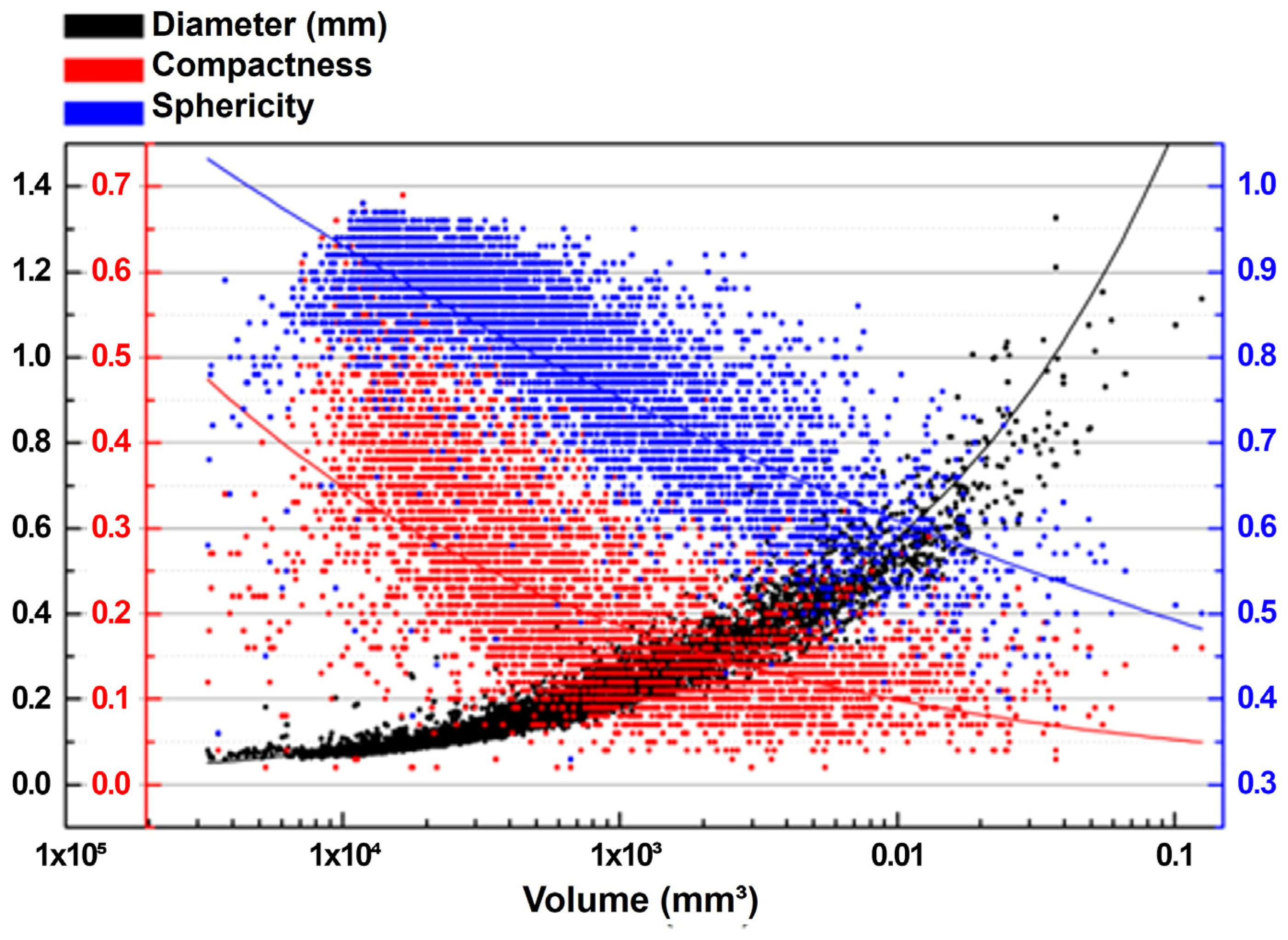
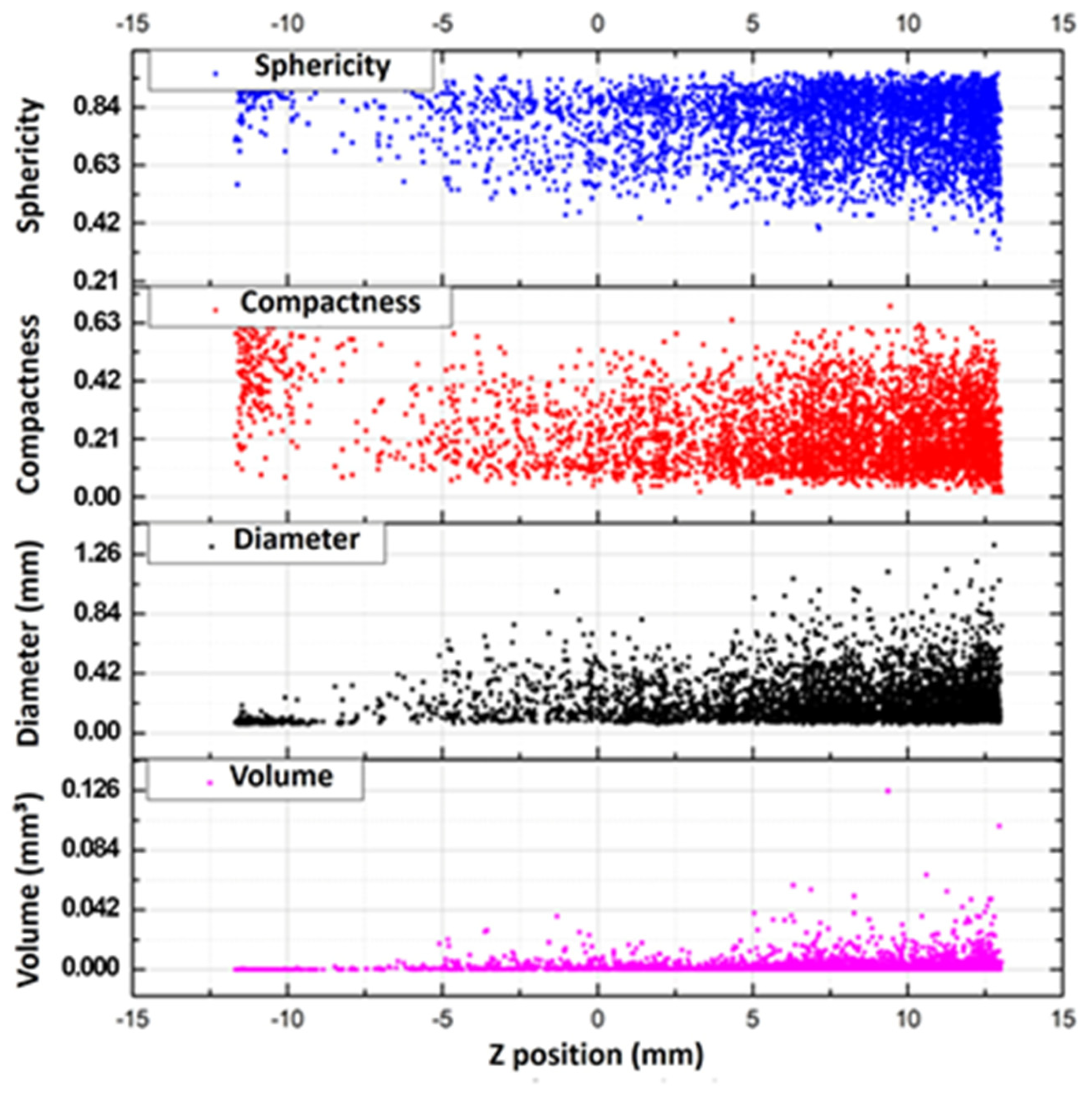
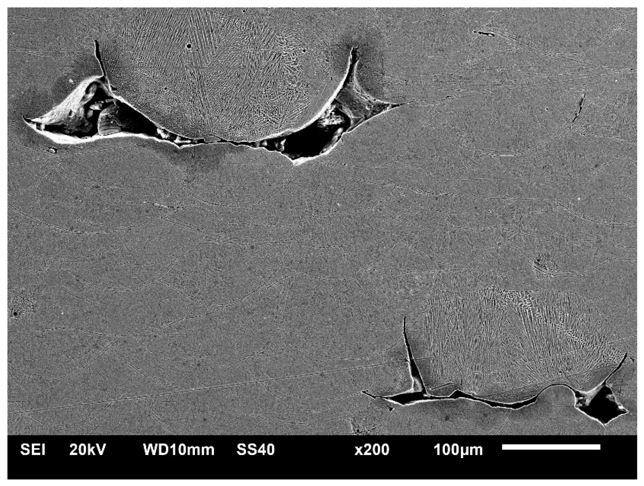
3.2. Porosity
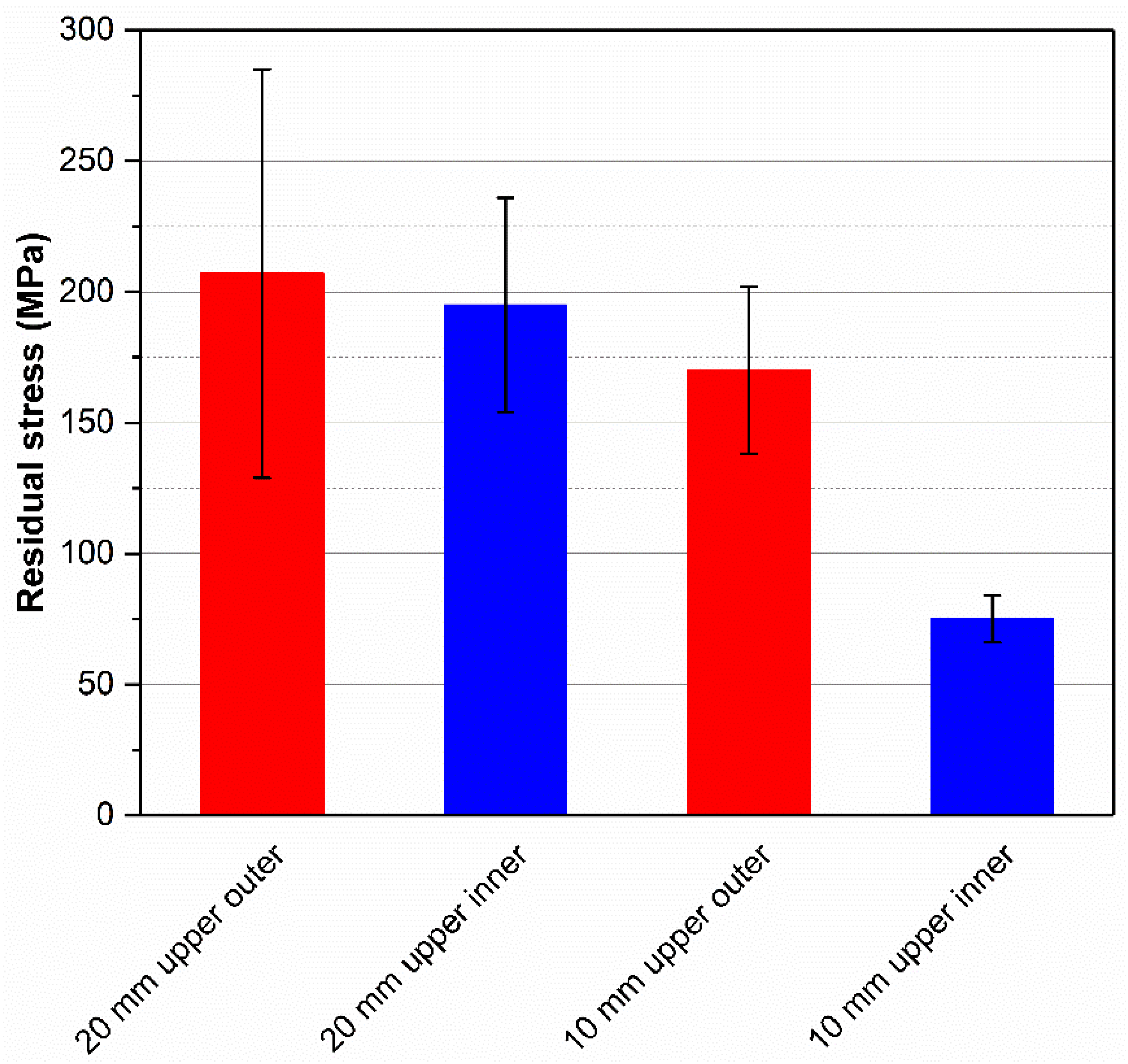
3.3. Residual Stresses
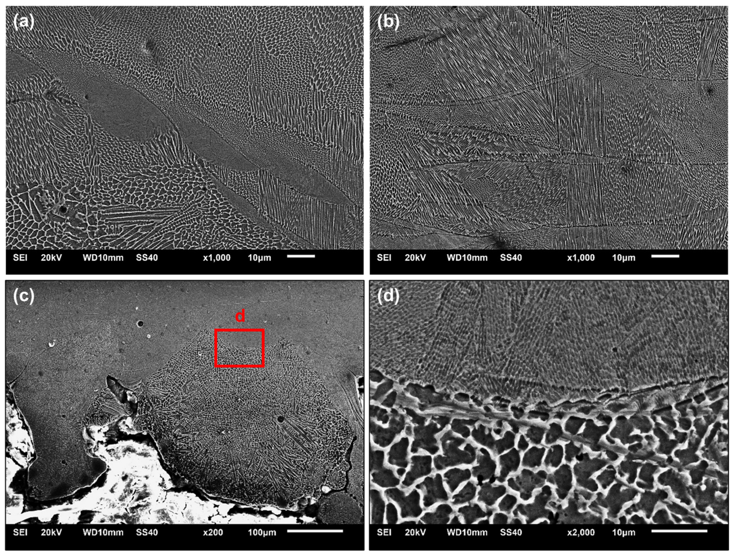
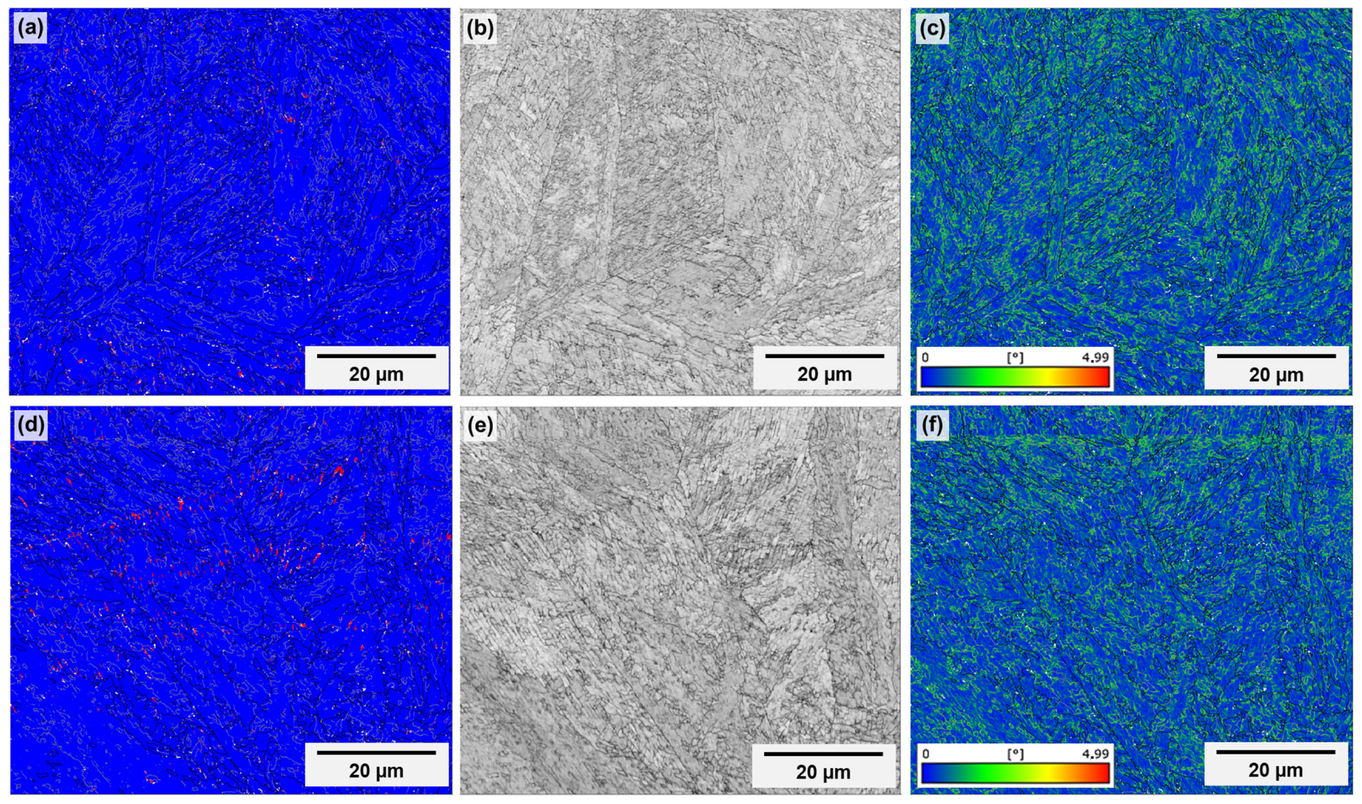
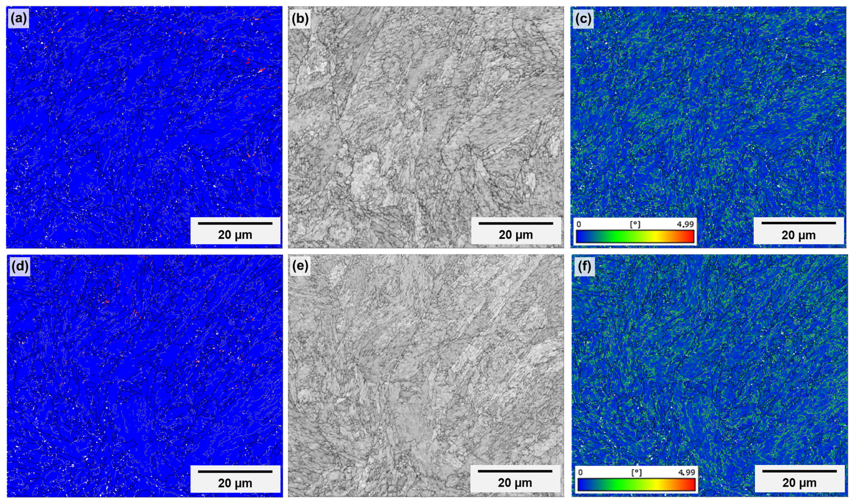
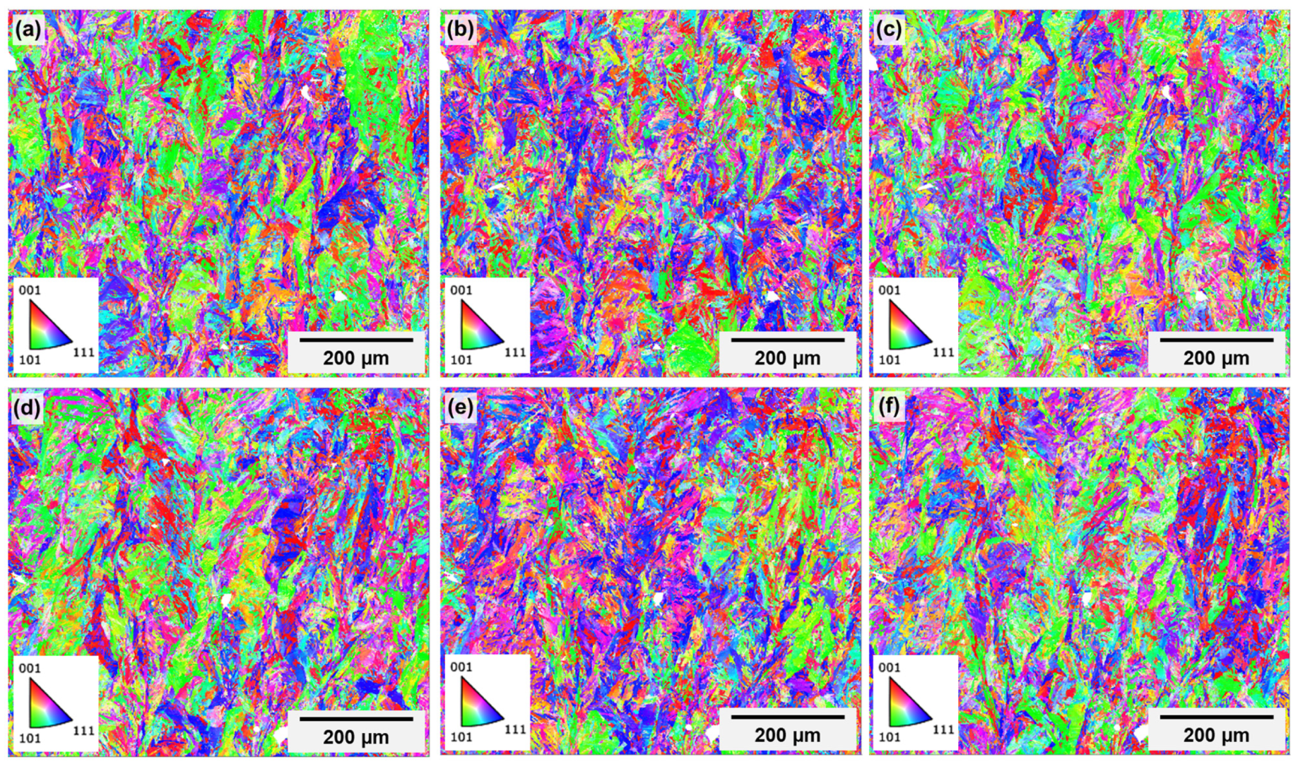
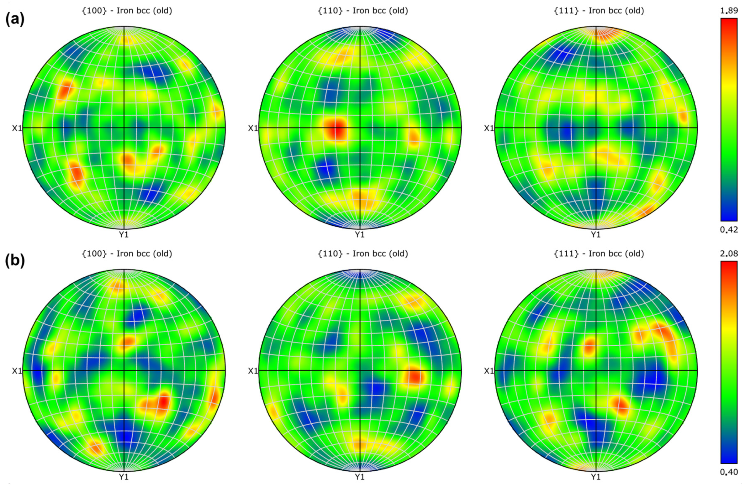
3.4. Microstructure
4. Conclusions
- Distortion in channels is primarily due to the lack of support structures, decreasing with increasing channel length. Statistical analyses showed that channel length exerts a significant influence on diameter variation. Distortion might affect the cooling efficiency of the channel due to its likely effects on fluid flow.
- High levels of porosity were observed above the channels, which can be attributed to layer irregularities caused by the absence of support. The porosity is characterized by large, irregular pores, which are more prevalent in the upper regions of specimens. The presence of porosity might reduce heat transfer between the channel and the part’s surface, also affecting the process’s efficiency when it comes to the cooling of forming tools.
- Residual stresses are tensile in nature, which can be ascribed to a “warping” tendency, and increase with channel length, as opposed to distortion, suggesting that higher levels of distortion contribute to a stress relief effect, with the same effect also being attributed to the presence of pores. On the top surface of specimens, stresses are higher than at the top of the channel. This effect may be critical because it makes the part prone to cracking and wear during operation. However, such effects might be at least partially mitigated by heat treatment, which will be the object of future study.
- Regardless of the specimen region, the microstructure is composed of cellular and columnar grains of the martensitic phase with different degrees of refinement, with no detectable presence of retained or reversed austenite. The upper inner region of the channel has an extremely irregular surface composed of partially melted particles. Such irregularity suggests an elevated roughness, which can also affect fluid flow and cooling efficiency.
- The crystallographic texture of martensite is nearly random, possibly due to a combination of the energy input and an optimized laser scanning strategy.
Author Contributions
Funding
Institutional Review Board Statement
Informed Consent Statement
Data Availability Statement
Acknowledgments
Conflicts of Interest
Abbreviations
| AM | Additive manufacturing |
| EBSD | Electron backscatter diffraction |
| KAM | Kernel average misorientation |
| LED | Light emitting diode |
| LPBF | Laser powder bed fusion |
| SEM | Scanning electron microscope/microscopy |
| XRD | X-ray diffraction |
References
- Guo, L.; Zhang, L.; Anderson, J.; Ojo, O. Additive Manufacturing of 18% Nickel Maraging Steels: Defect, Structure and Mechanical Properties: A Review. J. Mater. Sci. Technol. 2022, 120, 227–252. [Google Scholar] [CrossRef]
- Takata, N.; Nishida, R.; Suzuki, A.; Kobashi, M.; Kato, M. Crystallographic Features of Microstructure in Maraging Steel Fabricated by Selective Laser Melting. Metals 2018, 8, 440. [Google Scholar] [CrossRef]
- Mooney, B.; Kourousis, K.I.; Raghavendra, R.; Agius, D. Process Phenomena Influencing the Tensile and Anisotropic Characteristics of Additively Manufactured Maraging Steel. Mater. Sci. Eng. A 2019, 745, 115–125. [Google Scholar] [CrossRef]
- Asnafi, N.; Rajalampi, J.; Aspenberg, D.; Alveflo, A. Production Tools Made by Additive Manufacturing through Laser-Based Powder Bed Fusion. Berg. Huttenmann. Monatshefte 2020, 165, 125–136. [Google Scholar] [CrossRef]
- Law, W.K.; Wong, K.C.; Wang, H.; Sun, Z.; Lim, C.S. Microstructure Evolution in Additively Manufactured Steel Molds: A Review. J. Mater. Eng. Perform. 2021, 30, 6389–6405. [Google Scholar] [CrossRef]
- Tan, C.; Wang, D.; Ma, W.; Chen, Y.; Chen, S.; Yang, Y.; Zhou, K. Design and Additive Manufacturing of Novel Conformal Cooling Molds. Mater. Des. 2020, 196, 109147. [Google Scholar] [CrossRef]
- Feng, S.; Kamat, A.M.; Pei, Y. Design and Fabrication of Conformal Cooling Channels in Molds: Review and Progress Updates. Int. J. Heat Mass Transf. 2021, 171, 121082. [Google Scholar] [CrossRef]
- Dahmen, T.; Klingaa, C.G.; Baier-Stegmaier, S.; Lapina, A.; Pedersen, D.B.; Hattel, J.H. Characterization of Channels Made by Laser Powder Bed Fusion and Binder Jetting Using X-Ray CT and Image Analysis. Addit. Manuf. 2020, 36, 101445. [Google Scholar] [CrossRef]
- Belloli, F.; Demir, A.G.; Previtali, B. Understanding the Deformation Mechanisms of Horizontal Internal Channels during the LPBF of 18Ni300 Maraging Steel. J. Manuf. Process 2021, 71, 237–248. [Google Scholar] [CrossRef]
- Liu, C.; Cai, Z.; Dai, Y.; Huang, N.; Xu, F.; Lao, C. Experimental Comparison of the Flow Rate and Cooling Performance of Internal Cooling Channels Fabricated via Selective Laser Melting and Conventional Drilling Process. Int. J. Adv. Manuf. Technol. 2018, 96, 2757–2767. [Google Scholar] [CrossRef]
- Günther, J.; Leuders, S.; Koppa, P.; Tröster, T.; Henkel, S.; Biermann, H.; Niendorf, T. On the Effect of Internal Channels and Surface Roughness on the High-Cycle Fatigue Performance of Ti-6Al-4V Processed by SLM. Mater. Des. 2018, 143, 1–11. [Google Scholar] [CrossRef]
- Minguella-Canela, J.; Planas, S.M.; Iglesias, V.C.d.M.; López, M.A.d.l.S. Quantitative Analysis of the Effects of Incorporating Laser Powder Bed Fusion Manufactured Conformal Cooling Inserts in Steel Moulds over Four Types of Defects of a Commercially Produced Injected Part. J. Mater. Res. Technol. 2023, 23, 5423–5439. [Google Scholar] [CrossRef]
- Grosjean, C.; Borneat, J.C.; Hauteville, R.; Lefebvre, F.; Joffre, T. Effects of Channel Contour Laser Strategies on Fatigue Properties and Residual Stresses of Laser Powder Bed Printed Maraging Steel. Int. J. Adv. Manuf. Technol. 2022, 123, 3109–3120. [Google Scholar] [CrossRef]
- Baier, M.; Sinico, M.; Paggi, U.; Witvrouw, A.; Thijs, L.; Dewulf, W. Improving Metal Additive Manufacturing Part Design and Final Part Precision Using Feedback from X-Ray Computed Tomography. In Proceedings of the Special Interest Group Meeting on Advancing Precision in Additive Manufacturing, Nantes, France, 16–18 September 2019; EUSPEN: Bedfordshire, UK, 2019; pp. 23–26. [Google Scholar]
- Li, D.; Liu, X.; Hou, P.; Liao, H.; Qi, P.; Nie, R.; Shang, Y.; Jiao, Z. Deformation Prediction and Shape Compensation Model of Circular Channels Using Laser Powder Bed Fusion. J. Mater. Res. Technol. 2023, 27, 3968–3978. [Google Scholar] [CrossRef]
- Yang, T.; Chen, X.; Liu, T.; Wei, H.; Zhu, Z.; Liao, W. Effect of Processing Parameters on Overhanging Channel Forming Quality during Laser Powder Bed Fusion of AlSi10Mg. J. Manuf. Process 2024, 109, 537–548. [Google Scholar] [CrossRef]
- Islam, S.A.; Hao, L.; Javaid, Z.; Xiong, W.; Li, Y.; Jamil, Y.; Chen, Q.; Han, G. Surface Roughness of Interior Fine Flow Channels in Selective Laser Melted Ti-6Al-4V Alloy Components. Micromachines 2024, 15, 348. [Google Scholar] [CrossRef]
- Tian, Y.; Ren, H.; He, J.; Zha, X.; Lin, K.; Zhou, M.; Xiong, Y. Surface Roughness Improvement of Ti-6Al-4V Alloy Overhang Structures via Process Optimization for Laser-Powder Bed Fusion. J. Manuf. Process 2024, 110, 434–446. [Google Scholar] [CrossRef]
- Wang, D.; Mai, S.; Xiao, D.; Yang, Y. Surface Quality of the Curved Overhanging Structure Manufactured from 316-L Stainless Steel by SLM. Int. J. Adv. Manuf. Technol. 2016, 86, 781–792. [Google Scholar] [CrossRef]
- Cortina, M.; Arrizubieta, J.I.; Calleja, A.; Ukar, E.; Alberdi, A. Case Study to Illustrate the Potential of Conformal Cooling Channels for Hot Stamping Dies Manufactured Using Hybrid Process of Laser Metal Deposition (LMD) and Milling. Metals 2018, 8, 102. [Google Scholar] [CrossRef]
- Muvunzi, R.; Hagedon-Hansen, D.; Matope, S.; Madyibi, X.; Swart, C.B.; Nagel, M. Industry Case Study: Process Chain for Manufacturing of a Large Hybrid Hot Stamping Tool with Conformal Cooling Channels. Int. J. Adv. Manuf. Technol. 2020, 110, 1723–1730. [Google Scholar] [CrossRef]
- Pujante, J.; González, B.; Garcia-Llamas, E. Pilot Demonstration of Hot Sheet Metal Forming Using 3D Printed Dies. Materials 2021, 14, 5695. [Google Scholar] [CrossRef] [PubMed]
- Chantzis, D.; Liu, X.; Politis, D.J.; Shi, Z.; Wang, L. Design for Additive Manufacturing (DfAM) of Hot Stamping Dies with Improved Cooling Performance under Cyclic Loading Conditions. Addit. Manuf. 2021, 37, 101720. [Google Scholar] [CrossRef]
- Böhler Additive Manufacturing Powder: W722 AMPO/Fe-Based Alloys 2023. Available online: https://www.bohler-edelstahl.com/app/uploads/sites/248/productdb/api/w722-ampo_en_gb.pdf (accessed on 19 February 2025).
- Król, M.; Snopinski, P.; Hajnys, J.; Pagac, M.; Lukowiec, D. Selective Laser Melting of 18Ni-300 Maraging Steel. Materials 2020, 13, 4268. [Google Scholar] [CrossRef] [PubMed]
- Du Plessis, A.; Yadroitsev, I.; Le Roux, S.G. X-Ray Microcomputed Tomography in Additive Manufacturing: A Review of the Current Technology and Applications. 3D Print. Addit. Manuf. 2018, 5, 227–247. [Google Scholar] [CrossRef]
- Mugwagwa, L.; Yadroitsava, I.; Makoana, N.W.; Yadroitsev, I. Residual Stress in Laser Powder Bed Fusion. In Fundamentals of Laser Powder Bed Fusion of Metals; Yadroitsev, I., du Plessis, A., Yadroitsava, I., MacDonald, E., Eds.; Elsevier: Amsterdam, The Netherlands, 2021; pp. 245–276. [Google Scholar]
- Bartlett, J.L.; Li, X. An Overview of Residual Stresses in Metal Powder Bed Fusion. Addit. Manuf. 2019, 27, 131–149. [Google Scholar] [CrossRef]
- Noyan, I.C.; Cohen, J.B. Residual Stress: Measurement by Diffraction and Interpretation, 1st ed.; Springer: New York, NY, USA, 1987. [Google Scholar]
- Prevéy, P.S. X-Ray Diffraction Residual Stress Techniques. In Metals Handbook; ASM International: Novelty, OH, USA, 1986; Volume 10, pp. 380–392. [Google Scholar]
- Song, J.; Tang, Q.; Feng, Q.; Han, Q.; Ma, S.; Chen, H.; Guo, F.; Setchi, R. Effect of Remelting Processes on the Microstructure and Mechanical Behaviours of 18Ni-300 Maraging Steel Manufactured by Selective Laser Melting. Mater. Charact. 2022, 184, 111648. [Google Scholar] [CrossRef]
- Bai, Y.; Zhao, C.; Wang, D.; Wang, H. Evolution Mechanism of Surface Morphology and Internal Hole Defect of 18Ni300 Maraging Steel Fabricated by Selective Laser Melting. J. Mater. Process. Technol. 2022, 299, 117328. [Google Scholar] [CrossRef]
- Shange, M.; Yadroitsava, I.; Du Plessis, A.; Yadroitsev, I. Roughness and Near-Surface Porosity of Unsupported Overhangs Produced by High-Speed Laser Powder Bed Fusion. 3D Print. Addit. Manuf. 2022, 9, 288–300. [Google Scholar] [CrossRef]
- Hastie, J.C.; Kartal, M.E.; Carter, L.N.; Attalah, M.M.; Mulvihill, D.M. Classifying Shape of Internal Pores within AlSi10Mg Alloy Manufactured by Laser Powder Bed Fusion Using 3D X-Ray Micro Computed Tomography: Influence of Processing Parameters and Heat Treatment. Mater. Charact. 2020, 163, 110225. [Google Scholar] [CrossRef]
- Nudelis, N.; Mayr, P. A Novel Classification Method for Pores in Laser Powder Bed Fusion. Metals 2021, 11, 1912. [Google Scholar] [CrossRef]
- Baumgärtner, B.; Hussein, J.; Hausotte, T. Investigation of the Shape and Detectability of Pores with X-Ray Computed Tomography. J. Manuf. Mater. Process. 2023, 7, 103. [Google Scholar] [CrossRef]
- Sola, A.; Nouri, A. Microstructural Porosity in Additive Manufacturing: The Formation and Detection of Pores in Metal Parts Fabricated by Powder Bed Fusion. J. Adv. Manuf. Process. 2019, 1, e10021. [Google Scholar] [CrossRef]
- Liu, Y.; Wang, G.; Zeng, D. Prediction of Pore Evolution during Selected Laser Melting Solidification by a Finite Element-Phase Field Model. Model. Simul. Mat. Sci. Eng. 2020, 28, 065004. [Google Scholar] [CrossRef]
- Ghods, S.; Schultz, E.; Pahuja, R.; Montelione, A.; Wisdom, C.; Arola, D.; Ramulu, M. Powder Reuse and Its Contribution to Porosity in Additive Manufacturing of Ti6Al4V. Materialia 2021, 15, 100992. [Google Scholar] [CrossRef]
- Shange, M.; Yadroitsava, L.; Pityana, S.; Yadroitsev, I.; Du Plessis, A. Determining the Effect of Surface Roughness and Porosity at Different Inclinations of LBPF Parts. In Proceedings of the RAPDASA 2019, Durban, South Africa, 6–8 November 2019; RAPDASA: Pretoria, South Africa, 2019; pp. 40–51. [Google Scholar]
- Oliveira, J.P.; LaLonde, A.D.; Ma, J. Processing Parameters in Laser Powder Bed Fusion Metal Additive Manufacturing. Mater. Des. 2020, 193, 108762. [Google Scholar] [CrossRef]
- Brennan, M.C.; Keist, J.S.; Palmer, T.A. Defects in Metal Additive Manufacturing Processes. J. Mater. Eng. Perform. 2021, 30, 4808–4818. [Google Scholar] [CrossRef]
- Cortina, M.; Arrizubieta, J.I.; Ruiz, J.E.; Lamikiz, A. Thermomechanical Analysis of Additively Manufactured Bimetallic Tools for Hot Stamping. J. Manuf. Process 2020, 57, 905–918. [Google Scholar] [CrossRef]
- Tomanek, L.B.; Stutts, D.S.; Pan, T.; Liou, F. Influence of Porosity on the Thermal, Electrical, and Mechanical Performance of Selective Laser Melted Stainless Steel. Addit. Manuf. 2021, 39, 101886. [Google Scholar] [CrossRef]
- Mugwagwa, L.; Yadroitsev, I.; Matope, S. Effect of Process Parameters on Residual Stresses, Distortions, and Porosity in Selective Laser Melting of Maraging Steel 300. Metals 2019, 9, 1042. [Google Scholar] [CrossRef]
- Mugwagwa, L.; Dimitrov, D.; Matope, S.; Yadroitsev, I. Influence of Process Parameters on Residual Stress Related Distortions in Selective Laser Melting. Procedia Manuf. 2018, 21, 92–99. [Google Scholar] [CrossRef]
- Yao, Y.; Fan, L.; Ding, R.; Franke, C.; Yang, Z.; Liu, W.; Li, T.; Chen, H. On the Role of Cellular Microstructure in Austenite Reversion in Selective Laser Melted Maraging Steel. J. Mater. Sci. Technol. 2024, 184, 180–194. [Google Scholar] [CrossRef]
- Wu, L.; Das, S.; Gridin, W.; Leuders, S.; Kahlert, M.; Vollmer, M.; Niendorf, T. Hot Work Tool Steel Processed by Laser Powder Bed Fusion: A Review on Most Relevant Influencing Factors. Adv. Eng. Mater. 2021, 23, 2100049. [Google Scholar] [CrossRef]
- Kizhakkinan, U.; Seetharaman, S.; Raghavan, N.; Rosen, D.W. Laser Powder Bed Fusion Additive Manufacturing of Maraging Steel: A Review. J. Manuf. Sci. Eng. 2023, 145, 110801. [Google Scholar] [CrossRef]
- Kolomy, S.; Sedlak, J.; Zouhar, J.; Slany, M.; Benc, M.; Dobrocky, D.; Barenyi, I.; Majerik, J. Influence of Aging Temperature on Mechanical Properties and Structure of M300 Maraging Steel Produced by Selective Laser Melting. Materials 2023, 16, 977. [Google Scholar] [CrossRef] [PubMed]
- Mooney, B.; Kourousis, K.I. A Review of Factors Affecting the Mechanical Properties of Maraging Steel 300 Fabricated via Laser Powder Bed Fusion. Metals 2020, 10, 1273. [Google Scholar] [CrossRef]
- Mutua, J.; Nakata, S.; Onda, T.; Chen, Z.C. Optimization of Selective Laser Melting Parameters and Influence of Post Heat Treatment on Microstructure and Mechanical Properties of Maraging Steel. Mater. Des. 2018, 139, 486–497. [Google Scholar] [CrossRef]
- Tan, C.; Zhou, K.; Kuang, M.; Ma, W.; Kuang, T. Microstructural Characterization and Properties of Selective Laser Melted Maraging Steel with Different Build Directions. Sci. Technol. Adv. Mater. 2018, 19, 746–758. [Google Scholar] [CrossRef]
- Habassi, F.; Houria, M.; Barka, N.; Jahazi, M. Influence of Post-Treatment on Microstructure and Mechanical Properties of Additively Manufactured C300 Maraging Steel. Mater. Charact. 2023, 202, 112980. [Google Scholar] [CrossRef]
- Sun, H.; Chu, X.; Liu, Z.; Gisele, A.; Zou, Y. Selective Laser Melting of Maraging Steels Using Recycled Powders: A Comprehensive Microstructural and Mechanical Investigation. Metall. Mater. Trans. A 2021, 52, 1714–1722. [Google Scholar] [CrossRef]
- Schwartz, A.J.; Kumar, M.; Adams, B.L.; Field, D.P. (Eds.) Electron Backscatter Diffraction in Materials Science, 2nd ed.; Springer: Berlin/Heidelberg, Germany, 2009. [Google Scholar]
- Kannan, R.; List, F.; Joslin, C.; Rossy, A.M.; Nandwana, P. Effect of Volumetric Energy Density on Microstructure and Properties of Grade 300 Maraging Steel Fabricated by Laser Powder Bed Fusion. Metall. Mater. Trans. A 2023, 54, 1062–1069. [Google Scholar] [CrossRef]

| Source | Ni | Co | Mo | Ti | Al | Mn | Si | C | P | S |
|---|---|---|---|---|---|---|---|---|---|---|
| Supplier | 18.0 | 9.30 | 4.90 | 1.10 | 0.15 | ≤0.15 | ≤0.10 | ≤0.03 | ≤0.01 | ≤0.01 |
| Measured (average) | 18.60 | 8.44 | 4.70 | 0.95 | 0.16 | 0.03 | <0.005 | <0.005 | <0.005 | <0.005 |
| Measured (error) | 0.23 | 0.16 | 0.14 | 0.06 | 0.06 | <0.00 | <0.00 | <0.00 | <0.00 | <0.00 |
| Parameter | Value |
|---|---|
| Laser wavelength | 1070 nm |
| Laser power | 200 W |
| Laser focus size | 0.07 mm |
| Scanning speed | 350 mm/s |
| Layer thickness | 30 µm |
| Hatch spacing | 120 µm |
| Atmosphere | Argon 4.6 |
| Preheating | 80 °C |
| Printing direction | Horizontal |
| Scanning strategy | 67° rotation between subsequent layers |
| Parameter | t1 = 10 mm | t2 = 20 mm |
|---|---|---|
| Designed diameter (mm) | 8.0 | 8.0 |
| Printed diameter (mm) | 7.871 | 7.990 |
| Deviation (%) | −1.6% | −0.1% |
| Parameter | F-Value | df 1 | df 2 | p-Value |
|---|---|---|---|---|
| Diameter (mm) | 4.70 | 1 | 7 | 0.067 |
| Parameter | F-Value | df 1 | df 2 | p-Value |
|---|---|---|---|---|
| Diameter (mm) | 22.5 | 1 | 7 | 0.002 |
Disclaimer/Publisher’s Note: The statements, opinions and data contained in all publications are solely those of the individual author(s) and contributor(s) and not of MDPI and/or the editor(s). MDPI and/or the editor(s) disclaim responsibility for any injury to people or property resulting from any ideas, methods, instructions or products referred to in the content. |
© 2025 by the authors. Licensee MDPI, Basel, Switzerland. This article is an open access article distributed under the terms and conditions of the Creative Commons Attribution (CC BY) license (https://creativecommons.org/licenses/by/4.0/).
Share and Cite
Silva, B.C.d.S.; Callegari, B.; Seixas, L.F.; Król, M.; Sitek, W.; Matula, G.; Krzemiński, Ł.; Coelho, R.S.; Batalha, G.F. Investigation of Distortion, Porosity and Residual Stresses in Internal Channels Fabricated in Maraging 300 Steel by Laser Powder Bed Fusion. Materials 2025, 18, 1019. https://doi.org/10.3390/ma18051019
Silva BCdS, Callegari B, Seixas LF, Król M, Sitek W, Matula G, Krzemiński Ł, Coelho RS, Batalha GF. Investigation of Distortion, Porosity and Residual Stresses in Internal Channels Fabricated in Maraging 300 Steel by Laser Powder Bed Fusion. Materials. 2025; 18(5):1019. https://doi.org/10.3390/ma18051019
Chicago/Turabian StyleSilva, Bruno Caetano dos Santos, Bruna Callegari, Luã Fonseca Seixas, Mariusz Król, Wojciech Sitek, Grzegorz Matula, Łukasz Krzemiński, Rodrigo Santiago Coelho, and Gilmar Ferreira Batalha. 2025. "Investigation of Distortion, Porosity and Residual Stresses in Internal Channels Fabricated in Maraging 300 Steel by Laser Powder Bed Fusion" Materials 18, no. 5: 1019. https://doi.org/10.3390/ma18051019
APA StyleSilva, B. C. d. S., Callegari, B., Seixas, L. F., Król, M., Sitek, W., Matula, G., Krzemiński, Ł., Coelho, R. S., & Batalha, G. F. (2025). Investigation of Distortion, Porosity and Residual Stresses in Internal Channels Fabricated in Maraging 300 Steel by Laser Powder Bed Fusion. Materials, 18(5), 1019. https://doi.org/10.3390/ma18051019