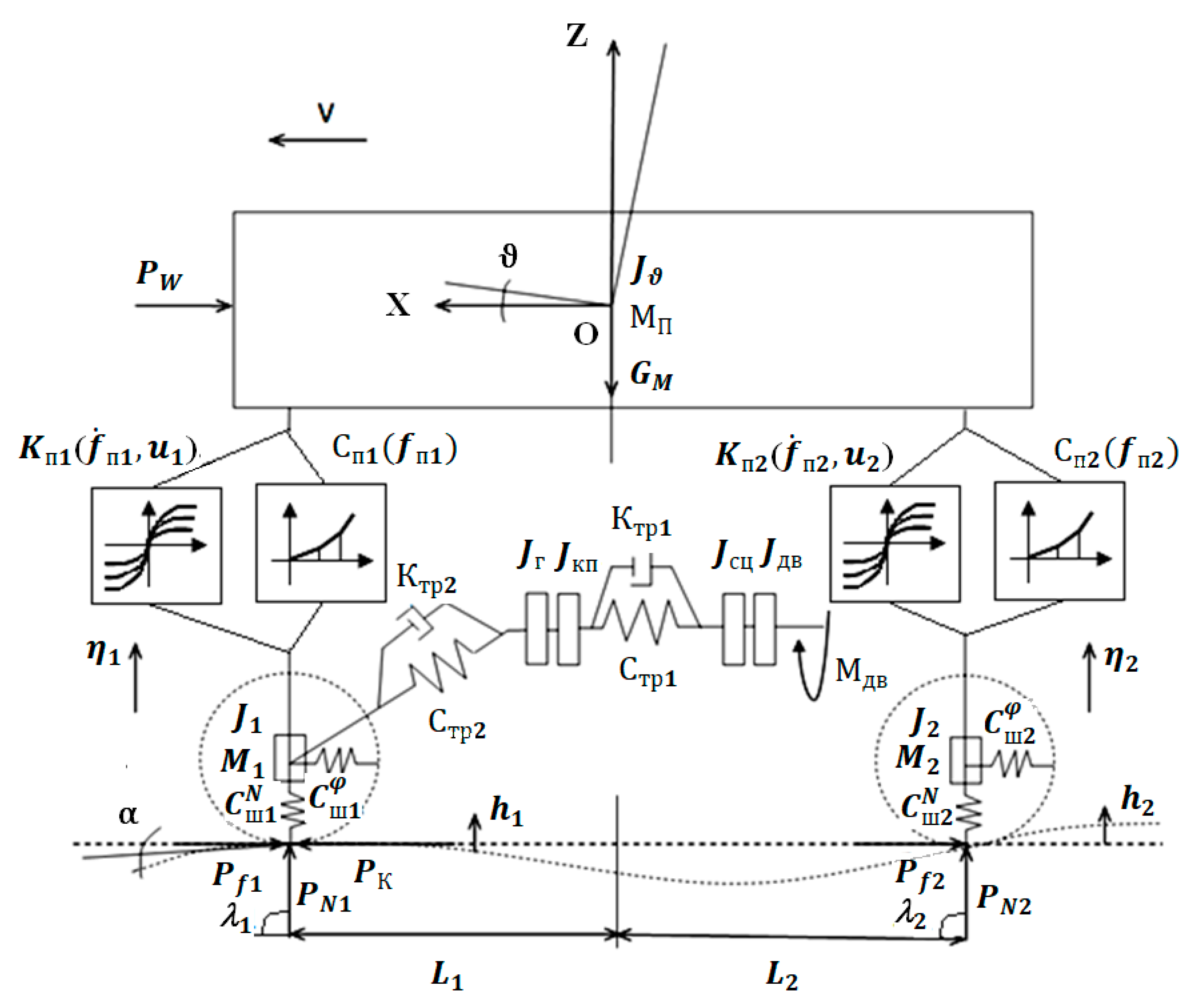
2.1. Design Scheme of a Car with Adaptive Suspension, Accepted Assumptions
So, let us consider a dynamic model of a front-wheel drive car with adaptive suspension [
5] moving on a non-straight road surface (
Figure 1). By the term “adaptive suspension”, we mean such a system of springing a car, the performance characteristics of which can be changed during its movement, depending on road conditions.
Figure 1 shows the following notation:
JДВ—flywheel that simulates rotating parts and links of a drive motor;
JСЦ—flywheel that simulates the rotating parts of the clutch disc and the drive links of the gearbox attached to it;
JКП—flywheel that simulates the rotating parts of the driven links of the gearbox;
JГ—flywheel that simulates rotating parts from the synchronizer of the engaged transmission to their car wheels;
СП1 (fП1), СП2 (fП2) —functional analogs of elastic elements with nonlinear performance characteristics of the front and rear suspensions, respectively;
KП1 (fП1, u1), KП2 (fП2,
u2) —functional analogues of adaptive shock absorbers for the front and rear suspensions;
fП1, fП2—the deformation of the front and rear suspension, respectively;
u1,
u2—control actions on the adaptive shock absorbers of the front and rear suspension, accordingly;
СТР1,
СТР2,
KТР1,
KТР2—coefficients of stiffness and damping of the corresponding sections of the transmission;
CNш1,
CNш2,
Cϕш1,
Cϕш2—coefficients of normal and angular stiffness of tires wheels of the front and rear axles, respectively;
α—angle of descent (ascent);
ϑ—angle of rotation of the sprung mass in the plane
XOZ;
MП—the mass of the sprung;
М1,
М2—unsprung masses, front and rear respectively;
η1,
η2—vertical movements of the corresponding unsprung masses;
h1,
h2—height of road profile irregularities under the corresponding wheels;
Pk—traction force;
Pf1,
Pf2—rolling resistance forces of the respective wheels;
PN1,
PN2 —reactions are normal for the wheels;
λ1,
λ2—the angles of inclination of the normal reactions;
PW—the force of air resistance.
The following assumptions are made when creating a dynamic car model:
The movement is flat (there is no movement in the transverse plane), the height of the road irregularities under the left and right sides is the same and the movement of unsprung masses occurs only perpendicular to the road plane, in the longitudinal direction along with the sprung mass;
We consider passenger cars of the middle class of segment B, up to 4.2 m long;
Front-wheel drive cars are considered;
There is no slippage at the point of contact of the wheel with the support surface;
Energy dissipation in suspension springs and silent blocks is not taken into account;
Deformation of silent blocks and similar suspension elements is not taken into account.
When developing the dynamic model, the model proposed by the authors V. A. Umnyashkin, N. M. Filkin, and R. S. Muzafarov was used as a basis [
6].
2.2. Mathematical Model of a Front-Wheel Drive Vehicle with Adaptive Suspension
Taking into account the accepted assumptions, the dynamical system under study has ten degrees of freedom. Let us write a vector of generalized coordinates:
here,
X—longitudinal movement of the vehicle;
Z—vertical movement of the sprung mass;
ϑ—angle of rotation of the sprung mass in the plane XOZ;
η1,
η2—vertical movements of the corresponding unsprung masses;
φдв,
φсц,
φкп,
φг—angles of rotation of parts of the corresponding sections of the transmission.
It should be noted that the dynamical system under study contains nonholonomic connections. Therefore, drawing up a mathematical model of car movement based on Lagrange equations of the second kind is unacceptable in this case. To create a mathematical model of the motion of the dynamical system under study, we use a special form of Lagrange equations of the second kind—Lagrange equations of the second kind with redundant coordinates [
7,
8,
9]:
here,
Т—kinetic energy of the system; П—potential energy of the system; Ф—Rayleigh dissipative function that characterizes the rate of mechanical energy dissipation;
Qk—generalized force, corresponding to the K-th generalized coordinate
; ′—the differential operator in the variable t;
—Lagrange multiplier [
10];
—additional Lagrange functions;
k ∈ {1, 2, …, 12}.
Redundant coordinates are not independent. Therefore, equations connecting redundant coordinates with independent generalized coordinates should be added to Equation (1)
here,
,
—projections of velocity vectors of points
N1 and
N2 per axle
OX.
Operating mode of the dynamic system under study—the transition process, which is “hitting a car on an unevenness and its subsequent passage”. In the mathematical formulation, the implementation of this process [
8,
9,
10,
11] corresponds to the solution of the Cauchy problem with the given initial conditions:
To use the developed functional analogs of elastic elements and adjustable shock absorbers in the mathematical model of car movement [
12,
13,
14], it is necessary to calculate partial derivatives of potential energy П and the dissipative function
Ф systems based on generalized coordinates and velocities. Calculation of the partial derivative of the terms of the potential energy of the system associated with elastic elements of suspensions from generalized coordinates is carried out by the relation:
For deformation of elastic elements
,
there is a function of vertical movement of the sprung mass Z, angle of rotation of the sprung mass ϑ and vertical displacements of the unsprung masses
,
. Perform the following transformations:
Applying the theorem on the derivative of an integral with a variable upper limit of integration, we obtain
Similar results can be obtained when differentiating over other generalized coordinates, as well as for calculating the derivative of the dissipative function Ф by generalized speeds.
Taking into account the results obtained, Equation (1) will take the Form (4).
here and further,
t—the “time” variable; ·—the differentiation operator for the variable
t.
Thus, the differential Equation (4), together with the initial conditions (3) and additional Equation (2), represent a mathematical model of the dynamic system under study “the movement of a front-wheel drive car with an adjustable suspension over standardized individual irregularities”.
2.4. Analysis of Bench Tests of the Dynamic System under Study
It should be noted that the results 1, 2, 3 obtained in the
Section 2.2 fully confirmed by experimental studies of cars, in particular, bench tests of the VW PASSAT CC car on a full-scale, stand of the front right quarter of the suspension of the VW PASSAT CC car (
Figure 2).
The stand (
Figure 2) includes a base 2, on which two symmetrically arranged vertical guides 1 of the movable load 3—a simulator of the “right front quarter” of the VW PASSAT CC car body—are fixed. The lower support 4 (silent block) of the right front suspension arm 5 is fixed to the movable load and and the upper support 6 of the shock strut 8 of the right front wheel 9. The elastic element 7 of the right front wheel is mounted on the shock strut. The composition of the stand also includes adjustable drive motor 10, the gear actuator support of the vibrator 12, 11 gauge “level” right front wheel, the sensor 13 measuring the force acting from the side wheel bearing 9 12 vibrator, 14 gauge measuring “bending the wheel”, the monitor 15 personal computer, recording the measured parameters and the control unit 16 of the degree of dissipation of adaptive suspension and oscillation frequency supports of the vibrator. The sensor 14 actually measures the distance from the center of the wheel 9 to the support 12 of the vibrator, i.e., the “dynamic radius” of the wheel. When the wheel is detached from the support, this sensor also measures the total distance from the center of the wheel to the support of the vibrator. However, in this case the measured value is equal to the sum of “static radius” wheels and a value of “rebound wheels”—the distance between the wheel surface and support. Thus, simulation of the vehicle on uneven, i.e., the simulation of the vertical oscillatory motion of a wheel, carried out by implementing a vertical reciprocating motion of the support 12. Moreover, the speed of movement along the irregularities is modeled by selecting the appropriate oscillation frequency of the support 12 and can be smoothly “changed” by adjusting the speed of the drive motor 10. “The height of the irregularities”, i.e., the oscillation amplitude of the support 12, can be continuously adjusted. However, in our experiments, the “height of the irregularities” was unchanged and was equal to 50 mm. All measurements were recorded on the PC 15, and the control of the frequency of vibrations of the support and of the degree of dissipation of the adaptive shock absorber were carried out using the control complex 16.
The movement of the vehicle on uneven leads to vertical oscillations of the wheel 9 and the movable load (the car body) 3. In some high-speed modes of motion of the irregularities (i.e., at certain vibration frequencies of the support 12 of the vibrator) and certain settings of the degree of dissipation of the shock absorber, the emerging phenomenon is “separating” wheels 9 from the support 12. In this case, as a rule, the amplitude of the vertical vibrations of the body and the amplitude of the vertical accelerations of the body increase significantly. These circumstances, in combination, significantly worsen the handling and safety of the car and dramatically increase the dynamic load of passengers and cargo, while significantly reducing the comfort and speed of the car as a whole and the effectiveness of stabilizing the position of its body.
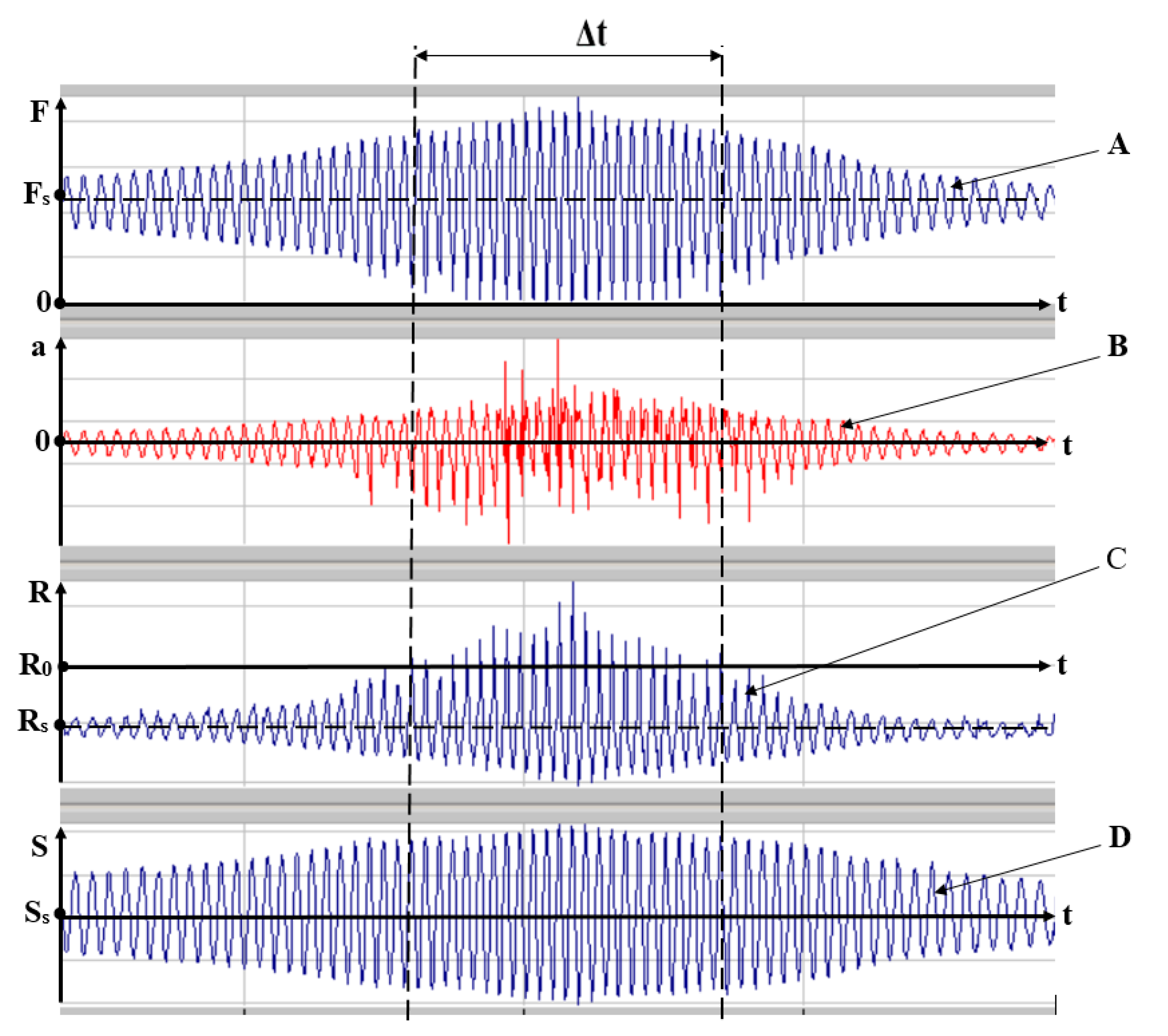
Figure 3 shows a fragment of the oscillogram test of the front suspension of the VOLKSWAGEN PASSAT CC car, which records the process of detaching the wheel 9 from the support 12.
Here, the curve A shows the amount of force F acting from the side of the wheel 9 on the support 12 of the vibrator, while Fs is the force acting on the support in the static state of the wheel (when the car is stationary). Curve B shows the value of the vertical acceleration a of the moving load 3-the simulator of the “right front quarter” of the body of the VW PASSAT CC car. The curve C shows the distance R from the center of the wheel to the support 12 of the vibrator. At the same time, Rs characterizes this distance in the static state of the car, when the car is stationary, and R0 is numerically equal to the “static radius” of the wheel 9. The curve D shows the value of the vertical movement (vibration) S of the moving load 3 (car body), Ss determines the vertical position of the car body in the static state of the car when the car is stationary. In these graphs, the abscissa axis is the “time” axis t of the process.
Note that if the condition is met,
There is a separation of the wheel 9 from the support 12. The uneven movement of the vehicle leads to vertical oscillations of the wheel 9 and the movable load (the car body) 3. In some uneven high-speed driving modes of the vehicle (i.e., at certain vibration frequencies of the support 12 of the vibrator) and the corresponding settings of the attenuator, the emerging phenomenon is “separating” wheels 9 from the support 12. Wheel detachments occur in the section Δt of the waveform. In this case, as a rule, the amplitude S(t) of the vertical vibrations of the body and the amplitude a(t) of the vertical accelerations of the body increase significantly, which is clearly recorded in the section Δt of the oscillogram. These circumstances, in combination, significantly worsen the handling and safety of the car and dramatically increase the dynamic load of passengers and cargo, while significantly reducing the comfort and speed of the car as a whole and the effectiveness of stabilizing the position of its body. We emphasize that it is on the section Δt of the waveform that the condition (5) is satisfied, i.e., the distance R from the center of the wheel periodically exceeds the value of the static radius R0 of the wheel, while, at the same time, the force F from the wheel on the support 12 periodically decreases to zero, i.e., the wheel 9 periodically breaks away from the support 12.
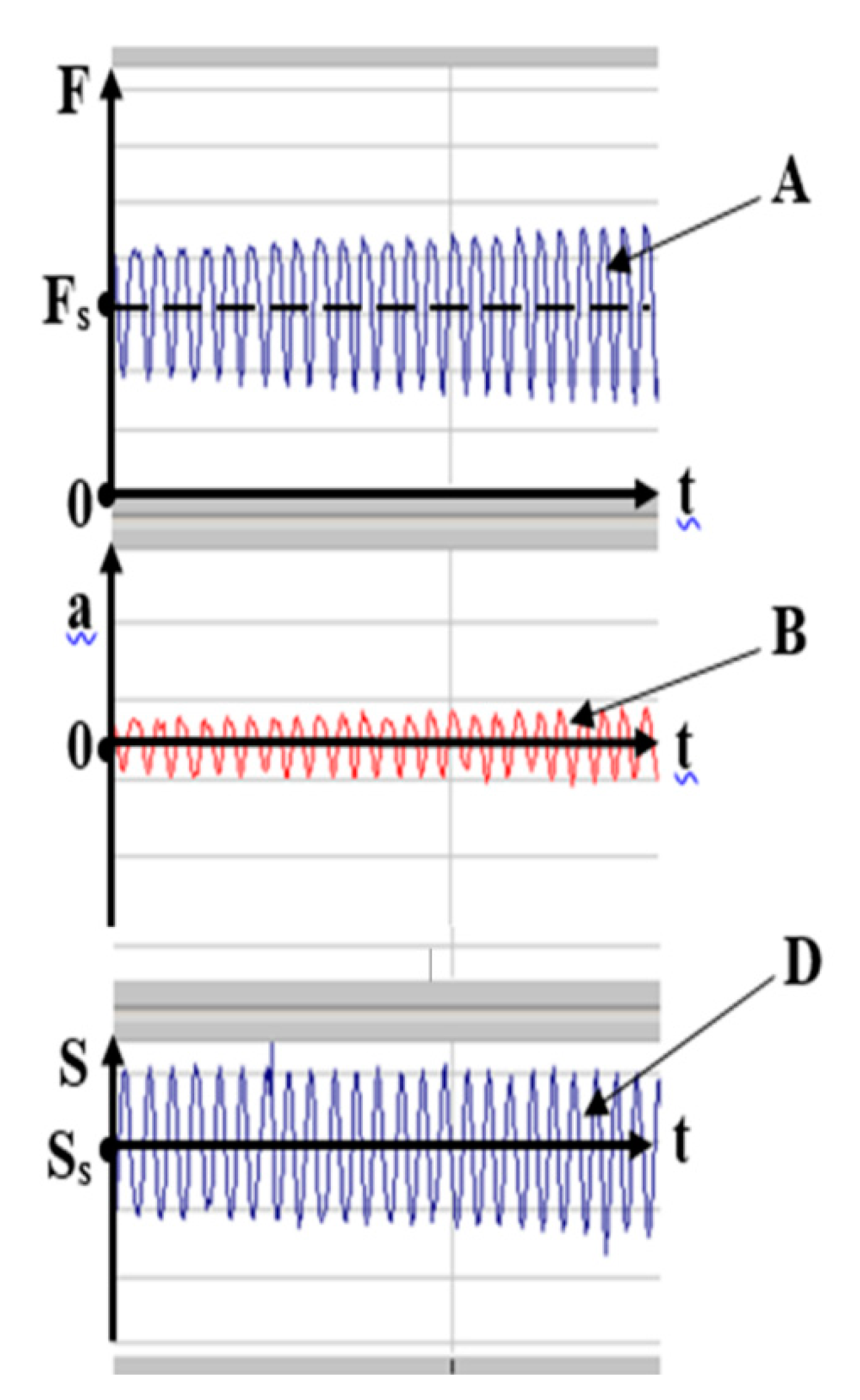
It should also be emphasized that this mode of wheel separation is fixed when using the standard, factory “tuning algorithm” of the shock absorber. These negative effects are eliminated throughout the entire range of frequencies mounts vibrator (all speeds of the driving mode of the vehicle on uneven) by, for example, the use of elastic elements of our design, or through the use of adaptive dampers our design. Of course, the noted negative phenomena will be even more effectively eliminated with the simultaneous introduction of elastic elements and adaptive shock absorbers of our designs into the suspension scheme.
Note that a direct comparison of the waveforms shown in
Figure 3 and
Figure 4 fully confirms the theoretical conclusions 1, 2, 3 mentioned in the
Section 2.2.
Thus, comparative theoretical and experimental simulation tests of the suspension of the VW PASSAT CC car when it moves along standard irregularities showed that
At some high-speed modes of movement of the car, there are inevitably modes of separation of the wheel from the supporting surface (from the surface of the roadway).
During the process of separation of the wheel from the road surface, as well as “approximation” to this process, the performance of the vehicle is much worse, in particular, disturbed wheels in contact with the surface of the roadway significantly increased the amplitude of the vertical oscillations of the body and the amplitude of the vertical accelerations of the body, which in turn, together, significantly affect the handling and safety and dramatically increase the dynamic loading of passengers and cargo, at the same time significantly reducing comfort, the speed of the car as a whole, and the effectiveness of stabilizing the position of its body.
The noted negative phenomena are eliminated in the entire speed range of the vehicle mode of movement on irregularities due to the use of elastic elements and adaptive shock absorbers of our designs in the vehicle springing systems.
2.5. Non-Local Use of Local Analysis Results
Thus, on the basis of a theoretical, “numerical” analysis of the dynamic system, it was possible to obtain information that is of great practical importance when creating structures for promising cars. However, strictly speaking, all the conclusions obtained are valid only for one car design—a passenger car of the middle class of the B segment, for the VW PASSAT CC car—and without further reservations, we cannot extend these findings even to other B-segment mid-range passenger cars. Moreover, we cannot even extend our conclusions to other “similar objects”, i.e., to other points in the space of constructive parameters of the dynamical system under study.
We show how this can still be done, i.e., back to the solution in this paper to the problem: Under what conditions the results obtained in the construction of the laws of motion of the dynamic system that are studied by numerical integration of differential equations of motion of its mathematical model (i.e., a “calculating” one point of the parameter space) can be used as a “nonlocal”, i.e., can be extended to the whole space of the design parameters of the studied dynamic system?
To this end, we introduce the space G1 of the design parameters of the dynamical system under study and the “extended” space G [
15,
16,
17]:
Next, we only need to bring the differential Equations (2) and (4) to the normal form [
1,
2] and make sure that the right-hand sides of the above-mentioned normal form in the space (6) satisfy the known Lipschitz conditions [
3]. If this property of the dynamical system under study holds, then, according to Picard’s theorem [
3], the solution of the Cauchy problem for Equations (2)–(4) exists and in the space G continuously depends on the parameters of the dynamical system under study. Hence the possibility of non-local use of the results of local analysis, i.e., the possibility of extending the analysis results only (directly calculated) point in space (6) on the whole space (6).
Thus, to address the question about the possibility of “non-local use of the results of local analysis of dynamic systems” enough to give the equations of motion of the studied dynamic system to normal and, further, to ensure that in the extended space of the design parameters of the studied dynamic system right part of the above mentioned normal form satisfy the well-known Lipschitz conditions.
We present a formulation of Picard’s theorem [
6].
Let us give a system of n first-order ordinary differential equations in “normal form”.
Let the initial condition also be given.
where (t0; X0) is some fixed point of (n + 1)-dimensional space.
Definition 1. By solving the system (7) on the interval (α; β) it is called a vector function X(t) Є C1(α; β), converting system (7) into a vector identity on the marked interval.
Definition 2. The solution of the Cauchy problem (7)–(8) is the solution of the system (7) that satisfies the condition (8).
Picard’s Theorem: Let the vector—function F(t, X) defined on the set
where
a,
b—some constants; and ∈
R;
b ∈
R;
R— the set of real numbers.
Let F (t, X) be continuous on the set with respect to t and all components of the vector X, and for any points (t, X1) and (t, X2) of the set, the Lipschitz condition is satisfied with respect to the argument X:
Then the solution of the Cauchy problem (7)—(8) exists, is unique, and is continuously differentiable at least on the segment
where
On the marked segment, the solution does not go beyond the set
The segment (9) is called the Picard segment, and the value is called the Lipschitz constant.
Note that for the example under consideration—solving the problem of “analyzing the dynamic properties of a VW PASSAT CC car equipped with adaptive suspension and moving at variable speed along an indirect road surface profile and developing recommendations for their radical improvement”, the Lipschitz conditions are feasible for all points in space (6).
It is interesting to note that similar comparative results were obtained in experimental studies of the dynamic properties of LADA-KALINA and RENAULT DUSTER cars on full-scale stands of the front right part of the suspension of the corresponding cars (the cars under study can be conditionally attributed to passenger cars of the middle class of the B segment). A good coincidence of the results obtained in this case indirectly confirms the validity of the approach we propose to implement the possibility of generalizing the results of studies of dynamical systems i.e., to implement the possibility of “non-local use of the results of local analysis”.

