Article

A Variable Parameter Ambient Vibration Control Method Based on Quasi-Zero Stiffness in Robotic Drilling Systems

1
School of Mechanical & Electronical Engineering, Lanzhou University of Technology, Lanzhou 730050, China
2
Department of Mechanical Engineering, University of Auckland, Private Bag 92019, Auckland 1142, New Zealand
*
Author to whom correspondence should be addressed.
Machines 2021, 9(3), 67; https://doi.org/10.3390/machines9030067
Submission received: 19 February 2021 / Revised: 15 March 2021 / Accepted: 19 March 2021 / Published: 21 March 2021
(This article belongs to the Section Automation and Control Systems)

Abstract

:
Vibrations in the aircraft assembly building will affect the precision of the robotic drilling system. A variable stiffness and damping semiactive vibration control mechanism with quasi-zero stiffness characteristics is developed. The quasi-zero stiffness of the mechanism is realized by the parallel connection of four vertically arranged bearing springs and two symmetrical horizontally arranged negative stiffness elements. Firstly, the quasi-zero stiffness parameters of the mechanism at the static equilibrium position are obtained through analysis. Secondly, the harmonic balance method is used to deal with the differential equations of motion. The effects of every parameter on the displacement transmissibility are analyzed, and the variable parameter control strategies are proposed. Finally, the system responses of the passive and semiactive vibration isolation mechanisms to the segmental variable frequency excitations are compared through virtual prototype experiments. The results show that the frequency range of vibration isolation is widened, and the stability of the vibration control system is effectively improved without resonance through the semiactive vibration control method. It is of innovative significance for ambient vibration control in robotic drilling systems.

1. Introduction

In the aviation manufacturing field, a lot of drilling and riveting is required to be carried out for assembly [1]. Due to the large size and complex profile of the parts of aircraft to be assembled, such as the wing, fuselage, engine and so on, it is difficult for traditional multiaxis machining centers to meet the flexibility of manufacturing and assembly of such large and complex structural parts. Robotic drilling has advantages of high efficiency, spatial accessibility, stability, flexibility and a fast refactoring capability for the assembly of large parts with complex shapes [2,3].
Robotic drilling systems can greatly improve the efficiency and precision of drilling and reduce the cost with their high flexibility and adaptability. Such systems have now been well researched and widely applied [4,5,6]. A robotic arm able to provide better stiffness than traditional industrial robots was proposed to improve the quality of holes in the drilling process [7]. Due to detrimental effects on surface finish in machining systems, a novel pregenerated matrix-based real-time chatter monitoring method for robotic drilling was presented in [8]. Andreas et al. presented a multisensor measurement system for robotic drilling. The system achieves high position accuracy and low vertical deviation [9]. Rodríguez et al. used liquefied CO2 as a cutting fluid for drilling CFRP-Ti6Al4V stacks as an alternative to dry-drilling, which effectively prolonged the life of the drilling system [10]. A method for extracting the geometric primitives of a circle in a three-dimensional space from a discrete point cloud data set obtained by a laser stripe sensor was introduced to the robotic drilling process in [11].
However, the improvement of the accuracy of robotic drilling systems is limited by the impact of ambient vibration in the aircraft assembly building. Ambient vibrations in the assembly building are independent of the robotic drilling system and are difficult to be controlled. The operation of other large equipment and the traveling of heavy overhead cranes are the main sources of ambient vibrations in the assembly building. The natural vibration frequency of large machine tools is relatively high. Taking large lathes and milling machines as examples, the frequency caused by spindle rotation is generally above 20 Hz, and that of some high-rotating lathes is above 100 Hz. Overhead cranes are essential large equipment for aircraft assembly. Taking for instance the double-beam type 100 T crane, the natural frequency of the full-load main beam structure is about 1 Hz. Generally, the frequency of the vibrations generated by large carrier vehicles is relatively low, and the range is between 5 and 8 Hz. Features of ambient vibrations, such as a wide frequency band and strong randomness, put forward a higher demand for vibration controllers. Therefore, it is necessary to design a suitable ambient vibration control system for robotic drilling systems.
At present, vibration control systems in different fields are well developed. A special magnetorheological damper is used to control the torsional vibration of a large turbo-generator rotor [12]. A vibration control system for milling is designed to mitigate the degradation of machined parts and tools caused by vibration in [13]. Arka et al. designed a vibration control system for spar-type floating wind turbines to reduce the vibration effect caused by the marine environment [14]. In [15], a boundary control approach method was used to control a two-link rigid-flexible wing. Al et al. studied the vibration control of a smart shell reinforced by graphene nanoplatelets under external load from the perspective of materials [16].
With the development of nonlinear structure research, new progress has been made in vibration control. As a typical nonlinear structure, the quasi-zero stiffness structure has characteristics of high static stiffness and low dynamic stiffness via the parallel connection of a positive and negative stiffness element. It can effectively widen the vibration isolation frequency band and improve the vibration isolation efficiency of the system.
In 1989, Alabuzhev systematically put forward a theory of a quasi-zero stiffness vibration control method and designed various mechanisms [17]. Based on this theory, a three-spring prototype of a quasi-zero stiffness vibration isolator with a spring fixed diagonally providing negative stiffness was further put forth in [18]. Cheng et al. found that the changes in load and excitation amplitude had impacts on vibration control performance [19]. A quasi-zero stiffness vibration isolator based on a shear lever mechanism was presented in [20], which cannot only guarantee the function of quasi-zero stiffness, but also has an adjustable capacity to adapt to a variation of load. A cam-roller vibration control system based on a quasi-zero stiffness mechanism was proposed in [21]. A kind of quasi-zero stiffness isolator equipped with three springs diagonally was designed in [22], which provides a wider quasi-zero stiffness region.
With the lucubration of the quasi-zero stiffness vibration control method, its practical application is also expanding. A practical application of a 2-DOF quasi-zero stiffness isolator was carried out in antiseismic engineering [23]. A vertical 2-DOF dynamic vibration absorber based on a quasi-zero stiffness mechanism was developed as well to abate the low-frequency vibration of high-speed trains in order to improve seat comfort [24]. Moreover, a quasi-zero stiffness mechanism was applied to pipeline vibration isolation in [25] to attenuate the lateral vibration of a pipeline for liquid transportation caused by foundation excitation.
This paper develops a quasi-zero stiffness vibration control method for a robotic drilling system. Considering the influence of nonlinear factors on the stability of the system, variable parameter methods are introduced on the basis of passive structure to make the system maintain stable vibration control performance. The organization of the paper is as follows. Section 1 describes the proposed system, analyzes its statics characteristics and determines the range of structural parameters. In Section 2, the dynamic equation of the system is established, the transfer rate characteristics of the system are derived and the effects of every parameter on the system are analyzed. The variable parameter methods are proposed in Section 3. In Section 4, the vibration control capability of the system is verified by ADAMS simulation. Finally, some conclusions and prospects are given in Section 5.

2. Design of the Vibration Control Mechanism Based on Quasi-Zero Stiffness

2.1. Structural Design

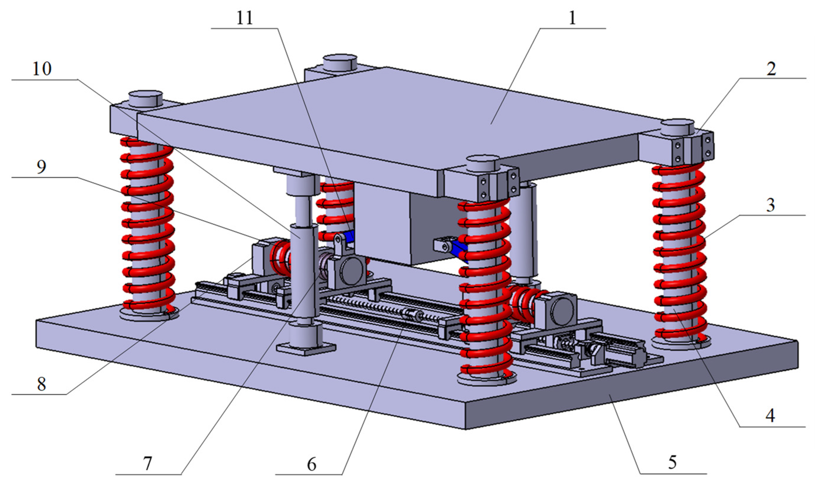
The robotic drilling system comprises a base, an industrial robot, an end-effector and a vibration control system, as shown in Figure 1. The structural stiffness of the robot is neglected as it is much higher than the springs. We only focus on studying the vibration control system. Here, the industrial robot and the load table of the vibration control system are considered mass. In addition, in Figure 2, the first group of springs near the middle in the horizontal direction mainly plays a buffering role, its stiffness is significantly less than that of other springs in the structure, and its influence on the system is negligible.
The system includes the load platform, bearing springs, negative stiffness elements, linear guide module and base. Bearing springs are arranged around the load platform symmetrically, and the direction constraint is realized through the guide rail. The negative stiffness elements are composed of two horizontal springs, connecting rods and several linear guide blocks. The restoring force of the springs acts on the platform through the connecting rods. The positive and negative stiffness elements are connected in parallel to form a typical quasi-zero stiffness structure. The linear guide module is driven by a servo motor to regulate the system stiffness actively. In order to be driven by a single motor, two ball screws with positive and negative threads, respectively, are connected by a coupling.

2.2. Passive Structural Parameters Analysis

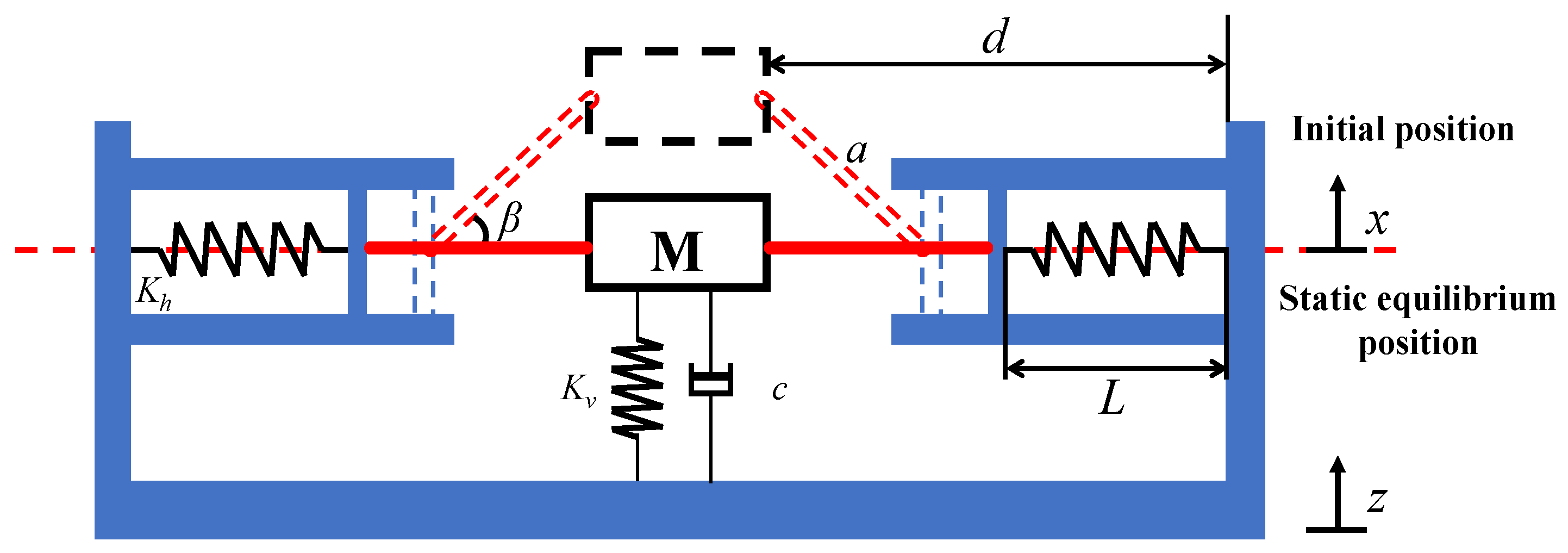
A schematic diagram of the quasi-zero stiffness structure is shown in Figure 3. The connecting rods are horizontal when the system is under load and in static equilibrium. The stiffness of the vertical and horizontal springs are Kv and Kh, respectively. The initial length of the horizontal spring is L0, the length after being compressed is L, the connecting rod length is a, the structural parameter is d, β represents the angle between the connecting rod and the static equilibrium position and the load quality is M. Taking the static equilibrium position as the coordinate origin, when the vibration control system is excited, the displacement from the static equilibrium position is x, and the expression of the spring restoring force F is:
F = F v + F h
F v = K v x
F h = 2 K h L 0 L tan β
L = d a 2 x 2
tan β = x a 2 x 2
Here, Fv and Fh are the restoring force of the vertical and horizontal springs, respectively. Substituting Equations (2)–(5) into Equation (1), the restoring force of the system can be derived as:
F = K v x + 2 K h d a 2 x 2 L 0 a 2 x 2 1 x
By differentiating Equation (6) with respect to the displacement x, the stiffness of the system is obtained as:
K = K v + 2 K h d L 0 a 2 x 2 + x 2 d L 0 a 2 x 2 3 2 1
The dimensionless parameters are introduced as:
f = F K v L 0 ;   u = x L 0 ;   α = K h K v λ 1 = a L 0 ;   λ 2 = d L 0 = L 0 + a 2 h L 0
where f is the dimensionless restoring force, u is the dimensionless displacement, λ1 and λ2 are the configuration parameters and α is the spring ratio.
Thus, the dimensionless restring force f and the dimensionless stiffness k can be derived from Equations (6) and (7) as
f = u + 2 α λ 2 λ 1 2 u 2 1 λ 1 2 u 2 1 u
K = K v + 2 K h d L 0 a 2 x 2 x 2 d L 0 a 2 x 2 3 2 1
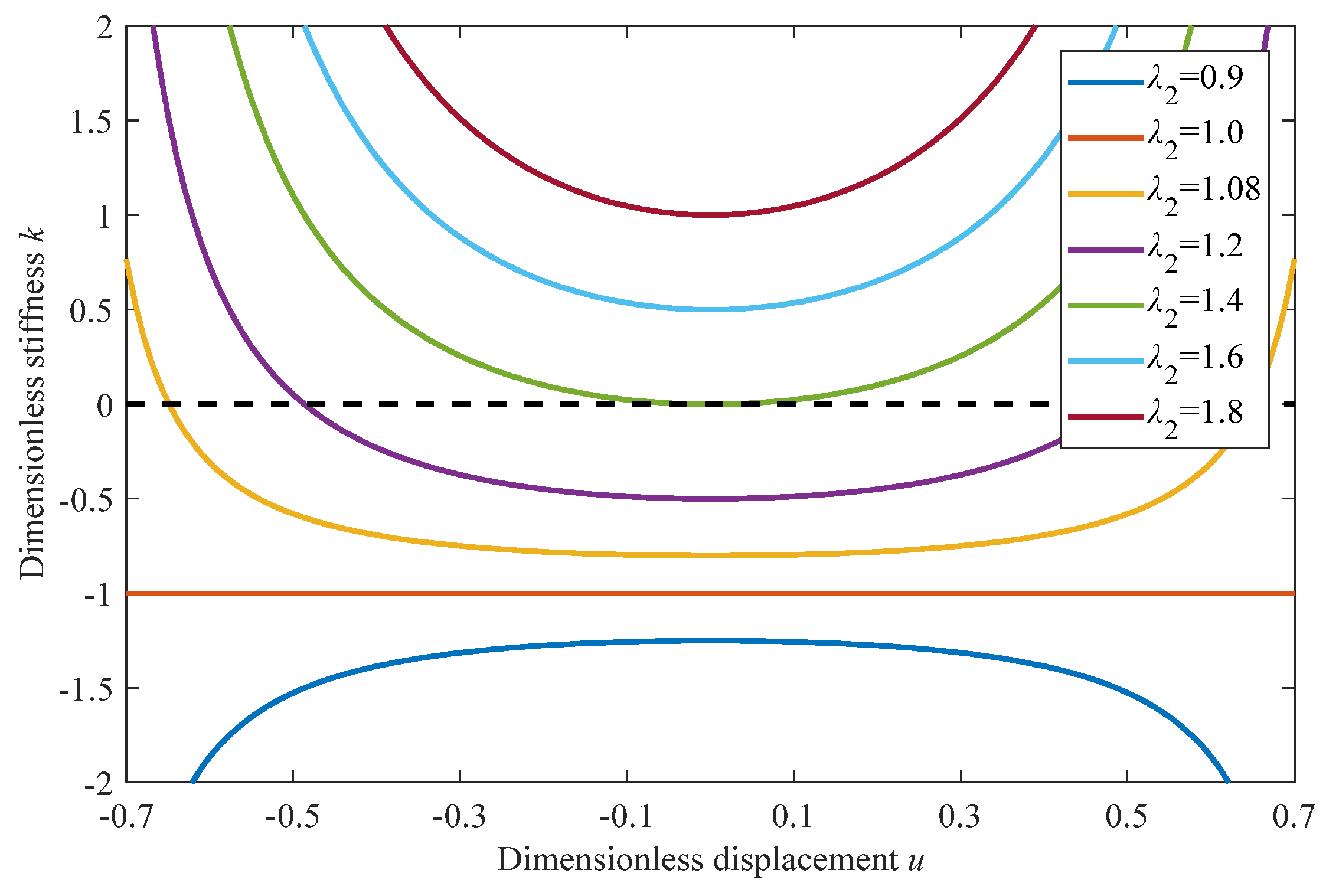
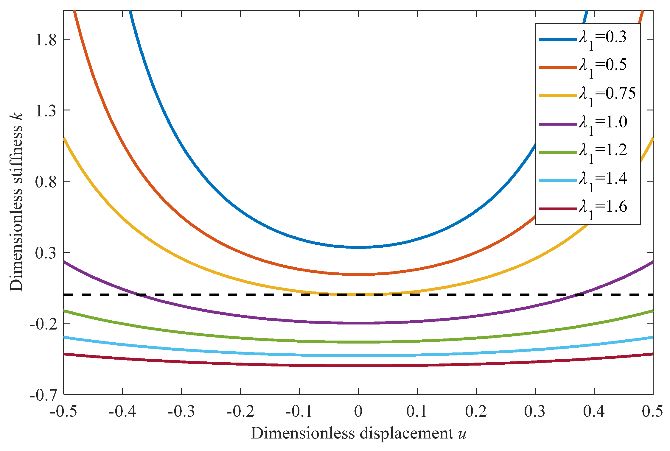
Equation (9) defines the relations among the static displacement, configurative parameters λ1 and λ2, the spring ratio α and the system stiffness, which are illustrated as Figure 4, Figure 5 and Figure 6.
As shown in Figure 4, the configurative parameter λ2 is set as a variable, while λ1 and α are set as constants. For the value of λ2 > 1, the system stiffness value is at the minimum at the static equilibrium position and greater than −1. It is obvious that the system is underloaded when the stiffness is negative. Therefore, configurative parameters should be selected to ensure that the system stiffness at the static equilibrium position is zero or greater than zero. For the value of λ2 < 1, the stiffness curve appears as an inverse bathtub curve, and the stiffness value is less than −1. The system does not achieve vibration control in this case, and the relevant analysis will not be made subsequently.
As shown in Figure 5, the configurative parameter λ1 is set as a variable, while λ2 and α are set as constants. For the value of λ2 = 1 and α = 1, the effects of λ1 on system stiffness are analyzed. The system stiffness value is at the minimum at the static equilibrium position, and both the stiffness and curvature decrease with λ1 increasing. Therefore, under the premise that the stiffness of the system at the static equilibrium position is zero or greater than zero, the configurative parameter λ1 should be as large as possible.
As shown in Figure 6, the configurative parameters λ1 and λ2 are set as constants, while α is set as a variable. For the value of λ2 = 0.8 and λ2 = 1.4, the effects of α on system stiffness are analyzed as well. The stiffness of the system decreases with α increasing. Under the condition that the stiffness value of the system at the static equilibrium position is zero or greater than zero, the spring ratio α should be as large as possible.
According to the above analysis, each parameter is required to satisfy that the system stiffness value at the static equilibrium position is equal to or greater than zero, thus we have
K sep = 1 + 2 α λ 2 λ 1 1 λ 1 0
where Ksep represents the system stiffness value at the static equilibrium position.
Therefore, when designing a passive vibration control system, the parameters should meet the following requirement:
λ 2 1 ,   but   λ 2 > 1 λ 2 1 < λ 1 α < λ 1 2 1 + λ 1 λ 2

3. Dynamics Analysis and Modeling

3.1. Dynamic Modeling and Solution of Quasi-Zero Stiffness Vibration Control Mechanism

In order to facilitate the subsequent dynamic analysis, an approximation of the dimensionless spring restoring force fa is made by expanding Equation (8) into a third-order Taylor series form at u = 0.
f a = 1 + 2 α λ 2 λ 1 1 λ 1 u + α λ 2 1 λ 1 2 u 3
The static equilibrium point is taken as the origin of coordinates of the mass M, and the coordinate directions of the mass and base are shown in Figure 7. The system is stimulated by the simple harmonic excitation z = Zcoswt, where Z is the excitation amplitude, and w is the excitation frequency. The differential equation of motion is established as follows.
M x ¨ + F a + c x ˙ z ˙ = 0
where Fa is the approximation of spring restoring force. Let y = xz, then convert Equation (13) into the form of the relative motion differential equation
M y ¨ + F a + c y ˙ = M Z e ω 2 cos ω t
The dimensionless parameters are defined as follows:
q = y L 0 ;   z e = Z e L 0 ;   ω n = K v M = ω ω n ;   ξ = c 2 K v M ;   τ = ω n t
Substitute the dimensionless parameters into Equation (14), we obtain
q ¨ + 2 ξ q ˙ + η q + ε q 3 = z e 2 cos γ τ
where η = 1 + 2 α λ 2 λ 1 1 λ 1 and ε = α λ 2 1 λ 1 3 .
Equation (15) can be solved by the harmonic balance method, and the steady-state response of the equation is assumed to be
q = A cos τ + θ
where A represents the response amplitude and θ the initial phase.
Let ϕ = Ωτ + θ, and substitute Equation (16) into the differential Equation (15), thus
η 2 A cos ϕ 2 ξ A sin ϕ + ε A 3 cos 3 ϕ = z e 2 cos ϕ θ
By using trigonometric functional relationships, the term of cos3ϕ is simplified as (3cosϕ)/4 by neglecting cos3ϕ. Let the coefficients of terms containing sinϕ and cosϕ on both sides of the equation be equal; we can get
η A + 3 4 ε A 3 A 2 = z e 2 cos θ
2 ξ A = z e 2 sin θ
By using sin2θ + cos2θ = 1, we can get the amplitude–frequency characteristic equation of the vibration control system:
A 2 z e 2 4 + 4 ξ 2 2 η 3 2 ε A 2 A 2 2 + η A + 3 4 ε A 3 2 = 0
The absolute displacement transmissibility of vibration is defined as the ratio of absolute displacements of the mass to that of the base
T a = A 2 + Z e 2 + 2 A Z e cos ϕ Z e = A Z e 2 + 1 + 2 A η A + 3 4 ε A 3 A γ 2 Z e γ 2

3.2. Stability Analysis

For the nonlinearity of the quasi-zero stiffness structure, the vibration control system may be unstable in some cases. In the unstable region, the system will not be able to achieve vibration control or even cause damage to the vibration isolated system, so it is essential to analyze the stability of the vibration control system.
The Mathieu equation discriminant method is used to analyze the stability of the system. A small perturbation n(t) is introduced into the steady-state solution of the dimensionless differential equation of motion.
The expression of the solution of the equation can be written as follows:
q = q 1 t + n t
where q1(t) is the steady-state solution.
Substituting Equation (22) into Equation (15)
q ¨ 1 + n ¨ + 2 ξ q ˙ 1 + n ˙ + η q 1 + n + ε q 1 3 + n 3 + 3 q 1 n 2 + 3 q 1 2 n = z e 2 cos τ
By combining Equations (23) and (15) and omitting the nonlinear high-order terms (the influence of high-order small perturbation on the system is very small), the differential equation of small perturbation n(t) is obtained:
n ¨ + 2 ξ n ˙ + η + 3 ε A 2 cos 2 τ + θ n = 0
Equation (24) is a Mathieu equation with a damping term. Let τ = τθ/Ω, and assume the solution for differential equation n(t) is:
n t = n 1 cos τ + n 2 sin τ
Substituting Equation (25) into Equation (24), combined with the trigonometric function, we have
n 1 2 cos τ n 2 2 sin τ + 2 ξ n 1 sin τ + n 2 cos τ + η n 1 cos τ + n 2 sin τ + 3 ε A 2 n 1 1 4 cos 3 τ + 3 4 cos τ + n 2 1 4 sin 3 τ + 1 4 sin τ = 0
The higher-order terms in Equation (26) could be ignored. Let the coefficients of both cosΩτ and sinΩτ equal zero to obtain the coefficient equations:
9 4 ε A 2 + η 2 n 1 + 2 ξ n 2 = 0 2 ξ n 1 + 3 4 ε A 2 + η 2 n 2 = 0
Let the discriminant of the coefficient equations be equal to 0, and the determination equation under the stability boundary conditions is obtained:
Δ = 4 + 3 ε A 2 2 η + 4 ξ 2 2 + 27 16 ε 2 A 4 + 3 ε A 2 η + η 2 = 0
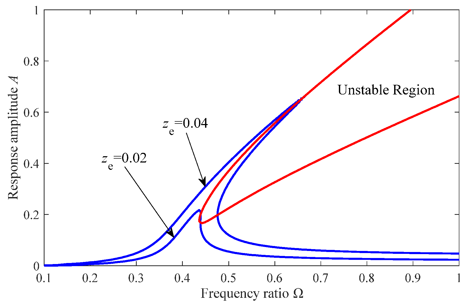
When ∆ < 0, the response of the vibration control system is unstable, and the corresponding unsteady region is as shown in Figure 8. When the excitation magnitude ze = 0.04, there are two intersection points between the amplitude–frequency characteristic and the stability boundary curves. The solution obtained in the unstable region is unstable; when the excitation amplitude decreases, the curves will not intersect, so the steady-state solution is always stable.

3.3. The Effects of the Parameters on Vibration Control Performance

3.3.1. Effects of Stiffness Ratio on Vibration Control Performance

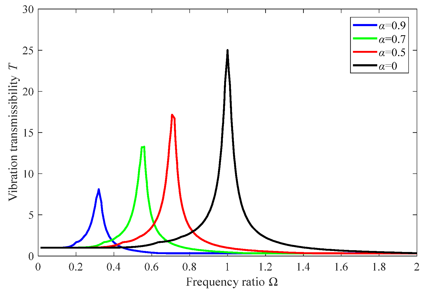
In order to study the effects of the nonlinear stiffness term on absolute displacement transmissibility, the stiffness value of the horizontal spring is set as a variable, while other parameters of the system are set as constants. As shown in Figure 9, both the frequency ratio at the peak value point and the peak value reduce with the increase of horizontal spring stiffness. Within the effective range of the stiffness value, the absolute displacement transmissibility is significantly reduced, and the vibration control performance is improved with the increase of the stiffness value. In addition, the effective range of frequency for vibration control increases with the increase of the stiffness of the horizontal spring.

3.3.2. Effects of Damping Coefficient on Vibration Control Performance

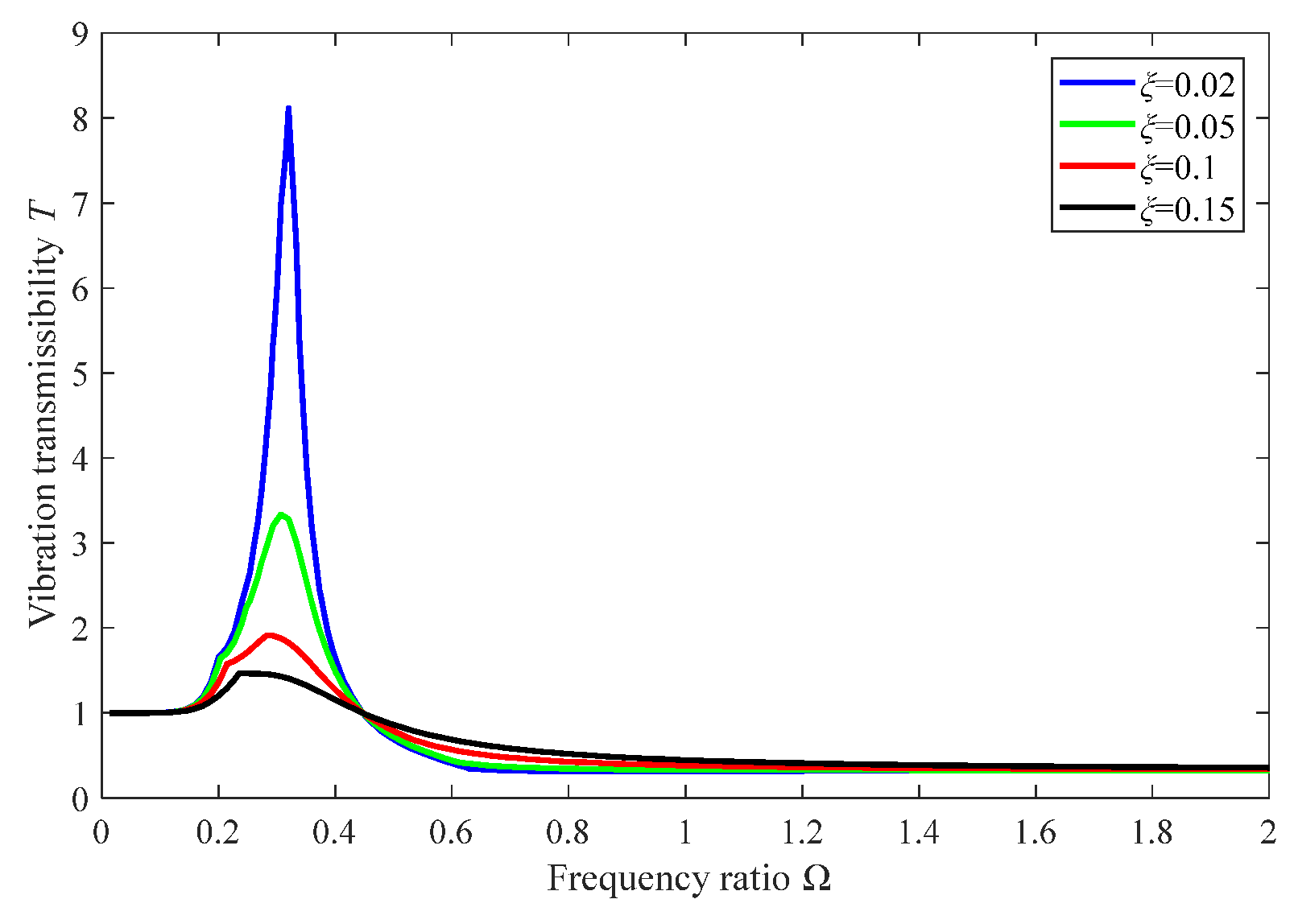
By setting the damping coefficient of the vertical damper as a variable, the absolute displacement transmissibility curves of various vertical damping conditions are obtained. As shown in Figure 10, with the increase of the damping coefficient, the resonance peak value of the system decreases correspondingly. However, the absolute displacement transmissibility decreases with the increase of the excitation frequency. Therefore, the appropriate damping coefficient is found out to ensure the vibration control efficacy of the system at medium and high frequencies while reducing the resonance peak value.
To sum up, the increase of the horizontal stiffness of the system and reduction of the vertical damping are conducive to reducing the absolute displacement transmissibility and improving the vibration control performance of the system.

4. Parameter Adjustment

The excitation characteristics of ambient vibration and the influence of different parameters on the absolute displacement transmissibility of the system are analyzed. The vibration suppression capacity of the system will be further optimized through parameter adjustment.

4.1. Variable Stiffness Control

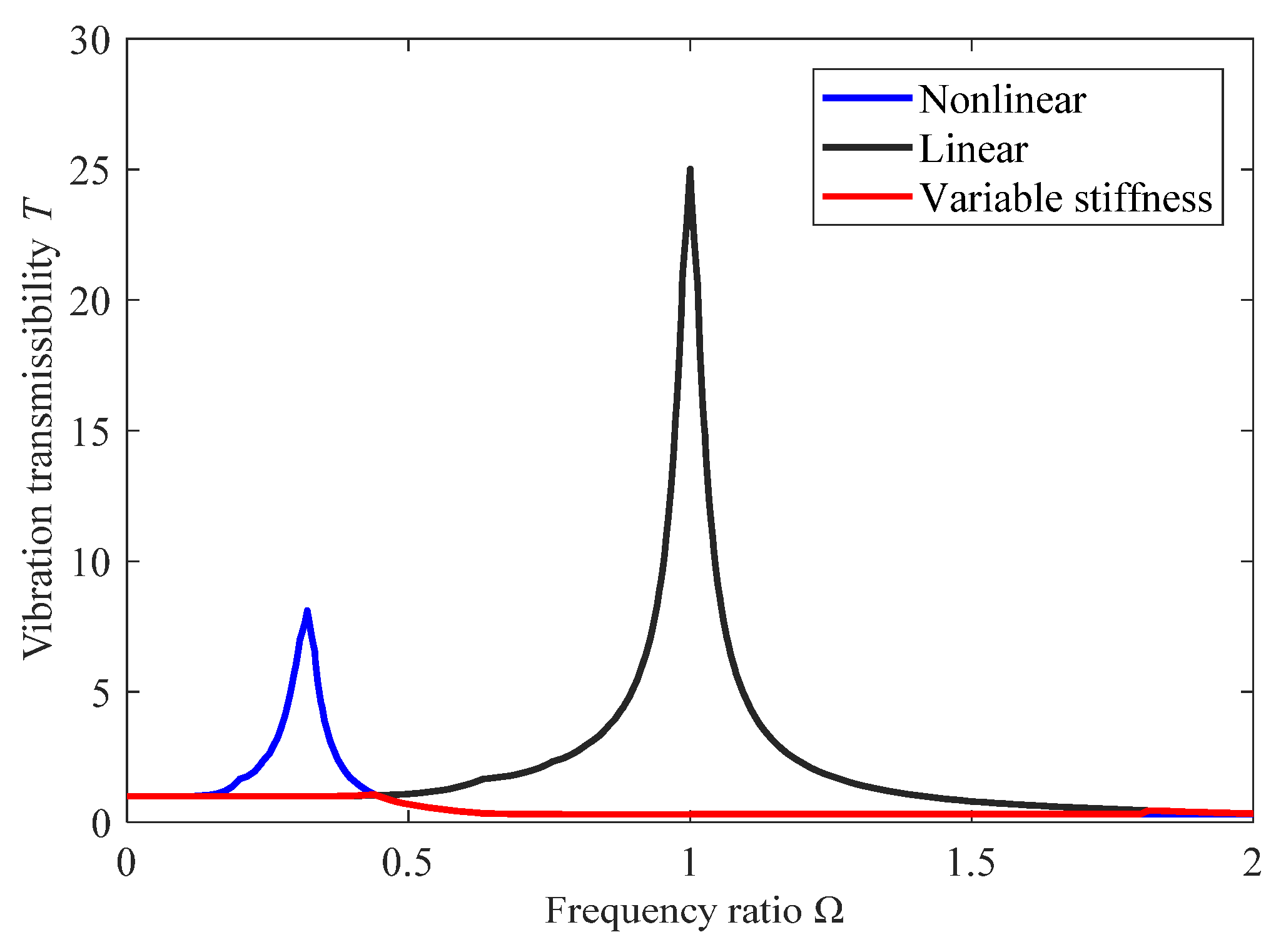
In order to ensure the stability of the system, the resonance region should first be avoided. It is known that the stiffness ratio affects the frequency interval in which the system resonates. Although the quasi-zero stiffness system can effectively reduce the resonance frequency, resonance will still occur in the low-frequency range, which is not allowed to exist in engineering applications. However, under the same conditions, the equivalent linear vibration isolation system has no resonance, and the vibration isolation performance is good; when the excitation frequency is large, it is obvious that the improvement of the vibration isolation performance of the nonlinear system is gradually weakened and lower than that of the linear system.
According to the above analysis, a piecewise variable stiffness method is adopted to control the system, which sets the input stiffness for adjustment according to different frequency segments of excitation. Figure 11 shows the transmissibility curves of the quasi-zero stiffness system and the linear system. It can be seen that when the excitation frequency ratio is 0.37, the transmissibility curve of the quasi-zero stiffness isolation system intersects with the equivalent linear system, taking 0.37 as the first frequency-critical point. When the frequency is high, it can be found that the transmissibility difference between the two systems gradually decreases, and 1.8 is selected as the second frequency-critical point. The vibration isolation effect of the variable stiffness system is obviously better than that of the passive system because it avoids the resonance frequency bands.
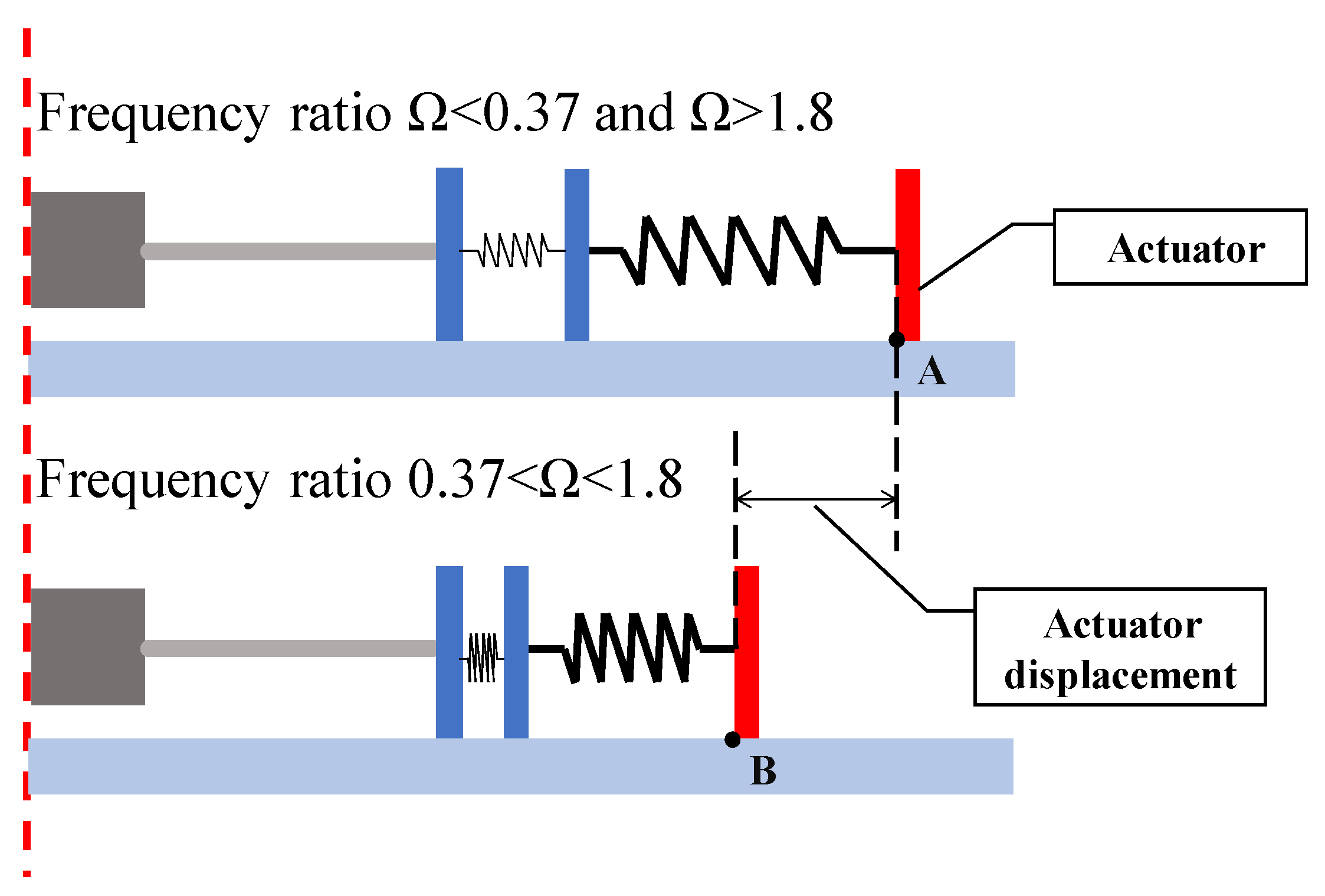
As shown in Figure 12, when the frequency ratio Ω < 0.37 or Ω > 1.8, the actuating slider is at Position A, and the negative stiffness element will not work in the structure. When the frequency ratio is 0.37 < Ω < 1.8, the actuating slider will be moved to Position B through the linear module so that the structure will have quasi-zero stiffness characteristics.

4.2. Variable Damping Control

It can be seen from the amplitude–frequency characteristic curve that the curve will jump under a certain excitation amplitude, which will have a great influence on the stability of the system. It is essential to determine the antijump condition of the system.
When a jump appears in the system, there will be at least two points on the curve that satisfy dΩ/dA = 0, and when dΩ/dA ≠ 0, the amplitude of the frequency is unique, so the system is stable. Therefore, there exists a critical value of the excitation amplitude to make sure that only one point of the amplitude–frequency characteristic curve satisfies dΩ/dA = 0. If the amplitude is greater than this critical condition, it will cause the jump phenomena of the system; otherwise, it will not.
The derivative of Equation (20) with respect to A is obtained
2 A 4 + 4 3 A 2 Z e 2 d d A + 8 ζ 2 A 4 η A 6 ε A 3 2 + 2 4 A 2 ζ 2 2 η A 2 3 2 ε A 4 d d A + 2 η A + 3 4 ε A 3 η + 9 4 ε A 2 = 0
Let dΩ/dA = 0, in the above equation, and further simplify
2 4 + 8 ζ 2 4 η 6 ε A 2 2 + 2 η + 3 4 ε A 2 η + 9 4 ε A 2 = 0
Equation (30) is a quadratic equation of one variable of Ω2, which is obtained by solving
2 = η + 3 2 ε A 2 2 ζ 2 ± 1 4 64 ζ 4 + 9 ε 2 A 4 64 η ζ 2 96 ε A ζ 2
Substituting the above equation into Equation (30),
A 2 z e 2 η + 3 2 ε A 2 2 ζ 2 ± 1 4 64 ζ 4 + 9 ε 2 A 4 64 η ζ 2 96 ε A ζ 2 2 + 4 ξ 2 2 η 3 2 ε A 2 A 2 η + 3 2 ε A 2 2 ζ 2 ± 1 4 64 ζ 4 + 9 ε 2 A 4 64 η ζ 2 96 ε A ζ 2 + η A + 3 4 ε A 3 2 = 0
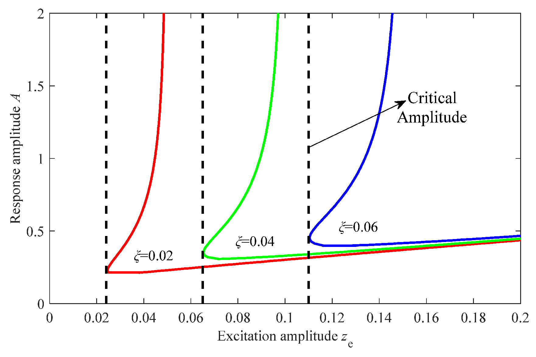
The curve of response amplitude A with excitation amplitude ze is shown in Figure 13. When the excitation amplitude is larger than the critical value, there are two amplitude points of the response, which are the jump-down and jump-up amplitude points. The larger the excitation amplitude, the larger the corresponding jump amplitude is. When the amplitude is equal to the critical value, the two jump points coincide. In this case, there is only one point of the amplitude–frequency characteristic curve that satisfies dΩ/dA = 0, and the system jump phenomenon disappears. When the excitation amplitude is less than the critical value, the jump amplitude point does not exist; that is, there is no jumping phenomenon in the system. Therefore, the critical value zc is the maximum permissible excitation amplitude under the premise that the vibration control system does not occur in the jumping phenomenon. Due to the randomness of ambient vibration, the excitation amplitude is uncontrollable, so it is necessary to adjust the parameters to avoid the influence of large amplitude on the stability.
The influence of the damping coefficient on the critical excitation amplitude is shown in Figure 13 as well. When the damping coefficient increases, the jump-up amplitude increases and the jump-down amplitude decreases. The critical excitation amplitude also increases obviously with the increase of the damping coefficient. Therefore, the variation of the damping coefficient is beneficial to avoid the occurrence of the jumping phenomenon.
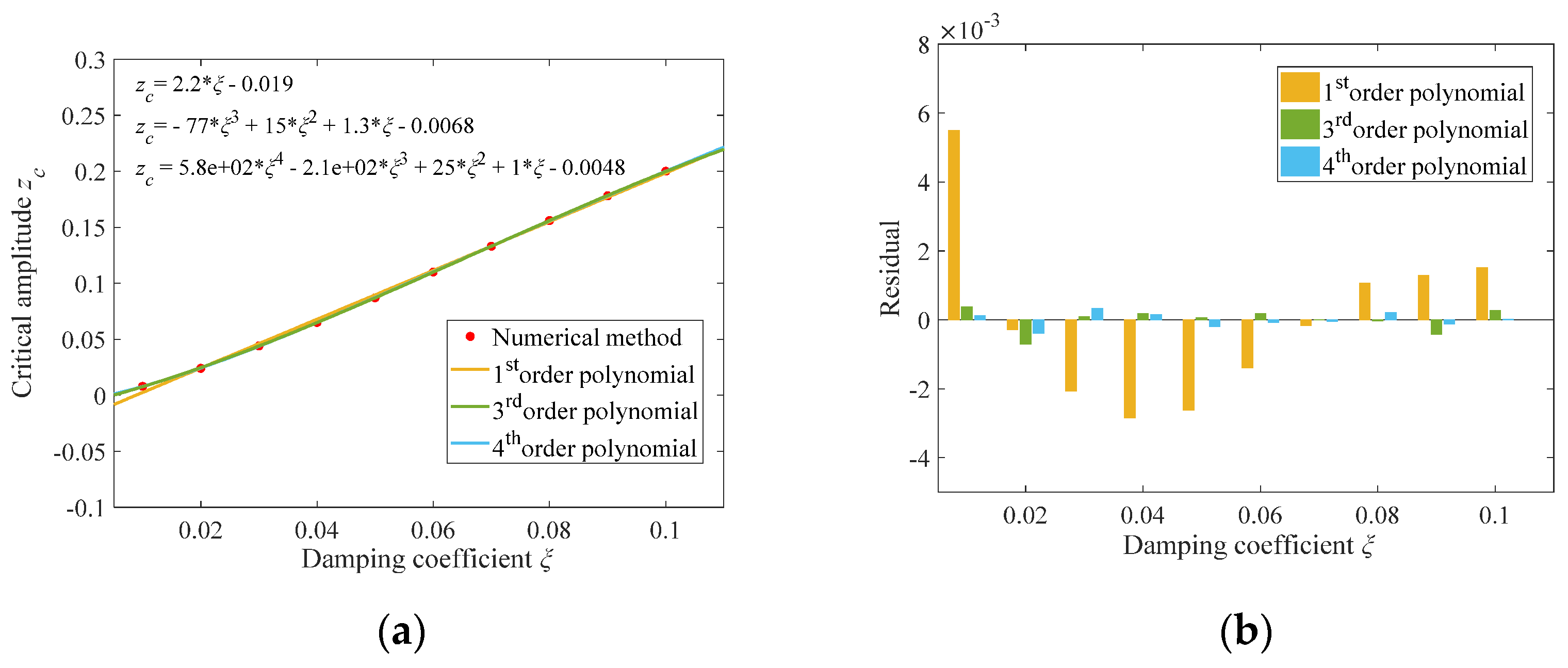
Because the equation of the jump amplitude is too complicated and difficult to analyze, the relationship between damping coefficient and critical amplitude is analyzed by numerical method. By data fitting, three fitting curves of first-, third- and fourth-order polynomials are plotted, respectively, as shown in Figure 14a. The error of the fitting curves is analyzed by the residual diagram, as shown in Figure 14b. Figure 14 shows that the third- and fourth-order curves are obviously more accurate than the first-order fitting curve, and the difference between the two curves is slight, so the third-order polynomial is selected.
z c = 77 ξ 3 + 15 ξ 2 + 1.3 ξ 0.0068

5. Simulation

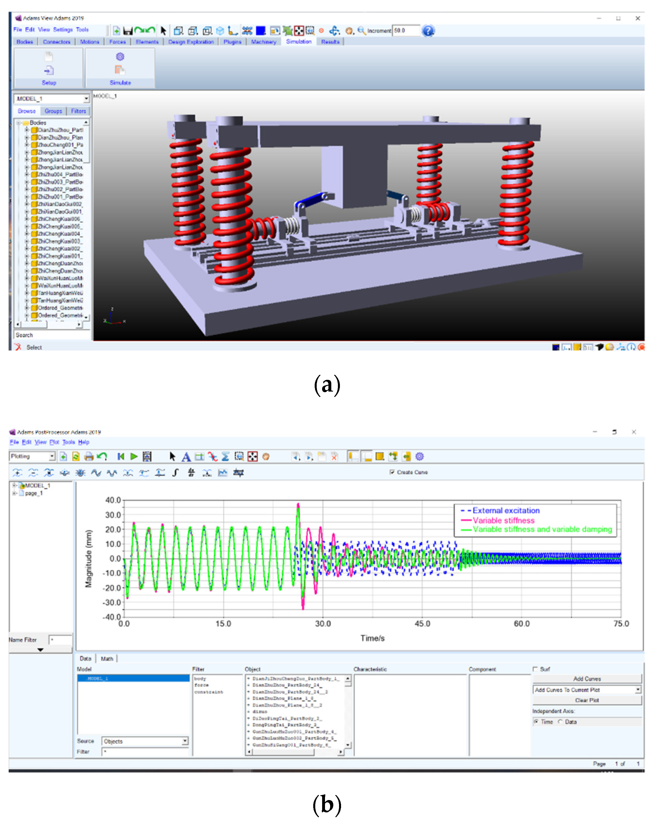
In order to verify the feasibility of the theoretical analysis results, this paper sets simulation parameters according to the KR-12-R1810-2 KUKA Industrial Robot, as shown in Table 1. Figure 15 shows the simulation operation interface.

5.1. Simulation of the Vibration Control System with Variable Stiffness

The external excitation is designed as a piecewise sinusoidal signal with variable frequency and invariable magnitude, and the expressions are shown as follows. The vibration control ability of different systems under the same excitation condition is compared and analyzed through simulations.
2 sin 3 t ,   0   s ~ 25   s 2 sin 10 t ,   26   s ~ 50   s 2 sin 40 t ,   51   s ~ 75   s
As shown in Figure 16, the two passive systems both have obvious resonance in different frequency bands. Especially in the time domain of 25–50 s, the response magnitude is about 12 times the excitation magnitude, and it will cause instability of the system. However, the system with variable stiffness can actively regulate the system to avoid instability according to excitation frequencies. It will effectively avoid resonance, broaden the frequency domain of vibration isolation and achieve stable vibration control.

5.2. Simulation of the Vibration Control System with Variable Stiffness and Damping

Considering that the excitation magnitude is also random, the variable magnitude feature is added.
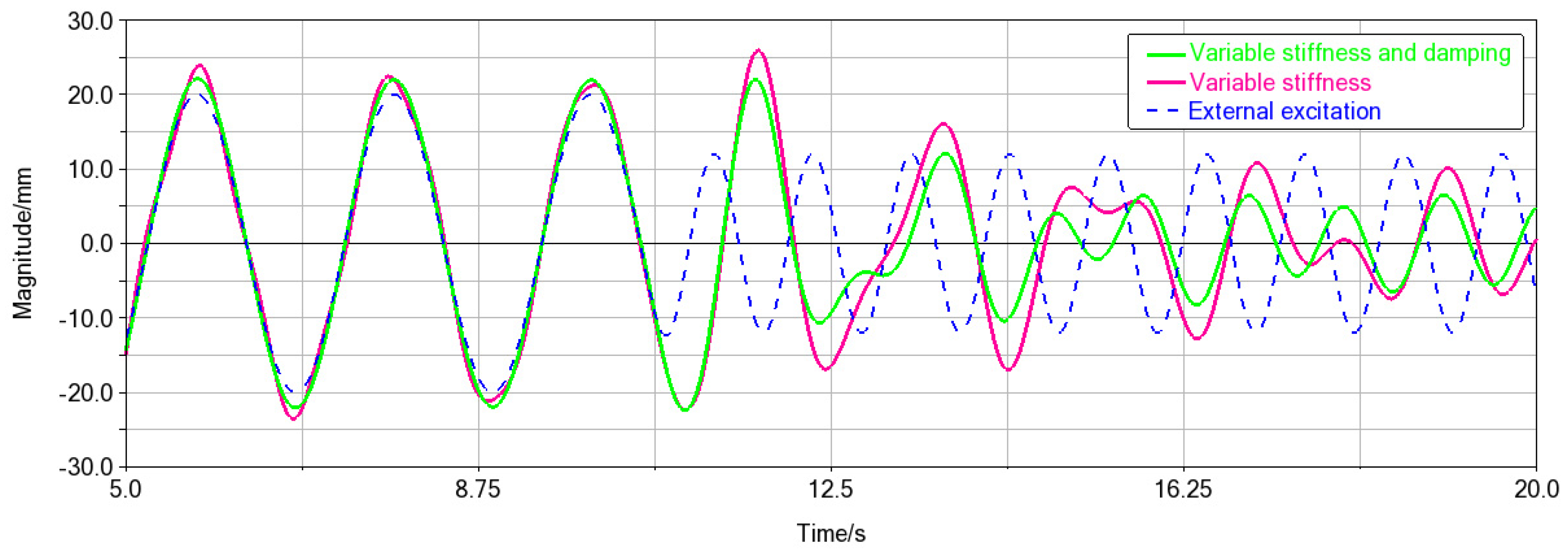
20 sin 3 t ,   0   s ~ 10   s 12 sin 6 t ,   11   s ~ 20   s
Under the condition that the excitation amplitude increases and the damping coefficient remains constant, the system will have an unstable region. As shown in Figure 17, due to the influence of instability, the vibration control of the variable stiffness system is not realized, and the response magnitude is obviously greater than that of the excitation, which may even affect the normal operation of the system. The variable damping active control is added to ensure the stability of the system under the condition of large magnitude and realize the optimization of the variable stiffness system.

6. Conclusions

An ambient vibration control system is developed to improve the precision and efficiency of robotic drilling systems. Based on the quasi-zero stiffness mechanism, a passive system is proposed, and the value ranges of system parameters are determined by static analysis. This paper studied the forced vibration of the system under basic harmonic excitation. The approximate dynamics equation in the form of the Duffing equation is obtained by approximating the system recovery force. The harmonic balance method is used to solve the amplitude–frequency characteristic equation effectively. Based on the functional relationship between the absolute displacement transmissibility and the excitation frequency of the system, the influence of stiffness ratio, damping coefficient and amplitude on the transmissibility is analyzed.
By adjusting the system stiffness ratio, the resonance frequency band is avoided, and the vibration isolation frequency band is broadened. Meanwhile, the stability and robustness of the system are improved under the condition of large excitation by adjusting the damping coefficient. The ADAMS simulation results show that the ambient vibrations are effectively suppressed by the semiactive vibration control system of variable parameters compared with the passive vibration control system under different frequency and amplitude excitation conditions.
At present, nonlinear dynamic vibration absorption systems have become a research hotspot in the field of vibration control. On the basis of the proposed structure, the nonlinear energy sink [26] theory can be introduced to further improve the vibration isolation performance.

Author Contributions

Conceptualization and methodology, C.Z. and L.Z.; formal analysis, C.Z., F.Q. and M.W.; writing—original draft preparation, C.Z.; supervision, L.Z. and J.S.D.; Funding acquisition, L.Z. All authors have read and agreed to the published version of the manuscript.

Funding

This research was funded by the National Natural Science Foundation of China, grant number 51765031 and Natural Science Foundation of Gansu Province, China, grant number 20JR5RA457.

Institutional Review Board Statement

Not applicable.

Data Availability Statement

Not applicable.

Acknowledgments

The authors gratefully acknowledge the helpful comments and suggestions of the reviewers, which have improved the presentation.

Conflicts of Interest

The authors declare no conflict of interest.

References

  1. Calawa, R.; Smith, S.; Moore, I.; Jackson, T. HAWDE five axis wing surface drilling machine. In Proceedings of the Aerospace Manufacturing and Automated Fastening Conference and Exhibition, St. Louis, MO, USA, 20–23 September 2004. [Google Scholar]
  2. Zhang, L.X.; Dhupia, J.S.; Wu, M.L.; Huang, H. A Robotic Drilling End-Effector and Its Sliding Mode Control for the Normal Adjustment. Appl. Sci. 2018, 8, 1892. [Google Scholar] [CrossRef] [Green Version]
  3. Zhang, L.X.; Dhupia, J.S.; Wu, M.L. Analysis and comparison of control strategies for normal adjustment of a robotic drilling end-effector. J. Vibroeng. 2018, 20, 2651–2667. [Google Scholar]
  4. Schneider, U.; Drust, M.; Ansaloni, M.; Lehmann, C.; Pellicciari, M.; Leali, F.; Gunnink, J.W.; Verl, A. Improving robotic machining accuracy through experimental error investigation and modular compensation. Int. J. Adv. Manuf. Technol. 2016, 85, 3–15. [Google Scholar] [CrossRef]
  5. Cano, R.; de Garayo, O.I.; Castillo, M.A.; Marin, R.; Ascorbe, H.; de los Santos, J.R. Flexible and Low-Cost Robotic System for Drilling Material Stacks. SAE Tech. Pap. 2016. [Google Scholar] [CrossRef]
  6. Mejri, S.; Gagnol, V.; Le, T.P.; Sabourin, L.; Ray, P.; Paultre, P. Dynamic characterization of machining robot and stability analysis. Int. J. Adv. Manuf. Technol. 2016, 82, 351–359. [Google Scholar] [CrossRef]
  7. Sun, L.F.; Liang, F.Y.; Fang, L.J. Design and performance analysis of an industrial robot arm for robotic drilling process. Ind. Robot 2019, 46, 7–16. [Google Scholar] [CrossRef]
  8. Tao, J.F.; Qin, C.J.; Xiao, D.Y.; Shi, H.T.; Liu, C.L. A pre-generated matrix-based method for real-time robotic drilling chatter monitoring. Chin. J. Aeronaut. 2019, 32, 2755–2764. [Google Scholar] [CrossRef]
  9. Andreas, F.; Jens, K.; Ira, E. Multi-sensor measurement system for robotic drilling. Robot Comput-Integr. Manuf. 2017, 47, 4–10. [Google Scholar]
  10. Rodríguez, A.; Calleja, A.; de Lacalle, L.N.L.; Pereira, O.; Rubio-Mateos, A.; Rodríguez, G. Drilling of CFRP-Ti6Al4V stacks using CO2-cryogenic cooling. J. Manuf. Process. 2021, 64, 58–66. [Google Scholar] [CrossRef]
  11. Al, K.T.; Bendemra, H.; Anwar, M.; Swart, D.; Dias, J. Introducing data analytics to the robotic drilling process. Ind. Robot 2018, 45, 371–378. [Google Scholar]
  12. Kumar, T.; Kumar, R.; Jain, S.C. Numerical Investigation of Semi-active Torsional Vibration Control of Heavy Turbo-generator Rotor using Magnetorheological Fluid Dampers. J. Vib. Eng. Technol. 2021. [Google Scholar] [CrossRef]
  13. Christopher, L.; Antoine, A.; Maxime, M. A magneto-rheological damper for on-site machining vibration control: From design to experimental characterization of its performance. Vibroeng. Procedia 2020, 34, 34–38. [Google Scholar]
  14. Arka, M.; Saptarshi, S.; Arunasis, C.; Sourav, D. Sway vibration control of floating horizontal axis wind turbine by modified spar-torus combination. Ocean Eng. 2021, 219, 108232. [Google Scholar]
  15. He, W.; Wang, T.T.; He, X.Y.; Yang, L.J.; Kaynak, O. Dynamical Modeling and Boundary Vibration Control of a Rigid-Flexible Wing System. IEEE ASME Trans. Mechatron. 2020, 25, 2711–2721. [Google Scholar] [CrossRef]
  16. Al, F.M.S.H.; Moghadam, S.A.; Dehini, R.; Shan, L.J.; Habibi, M.; Safarpour, H. Vibration control of a smart shell reinforced by graphene nanoplatelets under external load: Semi-numerical and finite element modeling. Thin-Walled Struct. 2021, 159, 107242. [Google Scholar]
  17. Alabuzhev, P.; Gritchin, A.; Kim, L.; Migirenko, G.; Chon, V.; Stepanov, P. Vibration Protecting and Measuring Systems with Quasi-Zero Stiffness; Rivin, E., Ed.; Hemisphere Pub. Corp.: New York, NY, USA, 1989; pp. 10–54. [Google Scholar]
  18. Carrella, A.; Brennan, M.J.; Waters, T.P.; Lopes, V., Jr. Force and displacement transmissibility of a nonlinear isolator with high-static-low-dynamic-stiffness. Int. J. Mech. Sci. 2012, 55, 22–29. [Google Scholar] [CrossRef]
  19. Cheng, C.; Li, S.M.; Wang, Y.; Jiang, X.X. Dynamic Analysis of Quasi-Zero Stiffness Vibration Isolator Considering Load Variation. J. Vib. Meas. Diag. 2017, 37, 743–749. [Google Scholar]
  20. Shi, P.C.; Yang, J.F.; Li, J.; Xiao, P. Design and simulation of shear-tension spring-type quasi-zero stiffness isolator. Vibroeng. Procedia 2020, 33, 159–163. [Google Scholar] [CrossRef]
  21. Ye, K.; Ji, J.C.; Brown, J. Design of a quasi-zero stiffness isolation system for supporting different loads. J. Sound Vib. 2020, 471, 115198. [Google Scholar] [CrossRef]
  22. Zhao, F.; Ji, J.C.; Ye, K.; Luo, Q.T. An innovative quasi-zero stiffness isolator with three pairs of oblique springs. Int. J. Mech. Sci. 2021, 192, 106093. [Google Scholar] [CrossRef]
  23. Zhu, G.N.; Liu, J.Y.; Cao, Q.J.; Cheng, Y.F.; Lu, Z.C.; Zhu, Z.B. A two degree of freedom stable quasi-zero stiffness prototype and its applications in aseismic engineering. Sci. China Techol. Sci. 2020, 63, 496–505. [Google Scholar] [CrossRef]
  24. Sun, Y.; Gong, D.; Zhou, J.S.; Sun, W.J.; Xia, Z.H. Low frequency vibration control of railway vehicles based on a high static low dynamic stiffness dynamic vibration absorber. Sci. China Techol. Sci. 2019, 62, 60–69. [Google Scholar] [CrossRef]
  25. Ding, H.; Ji, J.C.; Chen, L.Q. Nonlinear vibration isolation for fluid-conveying pipes using quasi-zero stiffness characteristics. Mech. Syst. Signal Process. 2019, 121, 675–688. [Google Scholar] [CrossRef]
  26. Ding, H.; Chen, L.Q. Designs, analysis, and applications of nonlinear energy sinks. Nonlinear Dyn. 2020, 100, 3061–3107. [Google Scholar] [CrossRef]
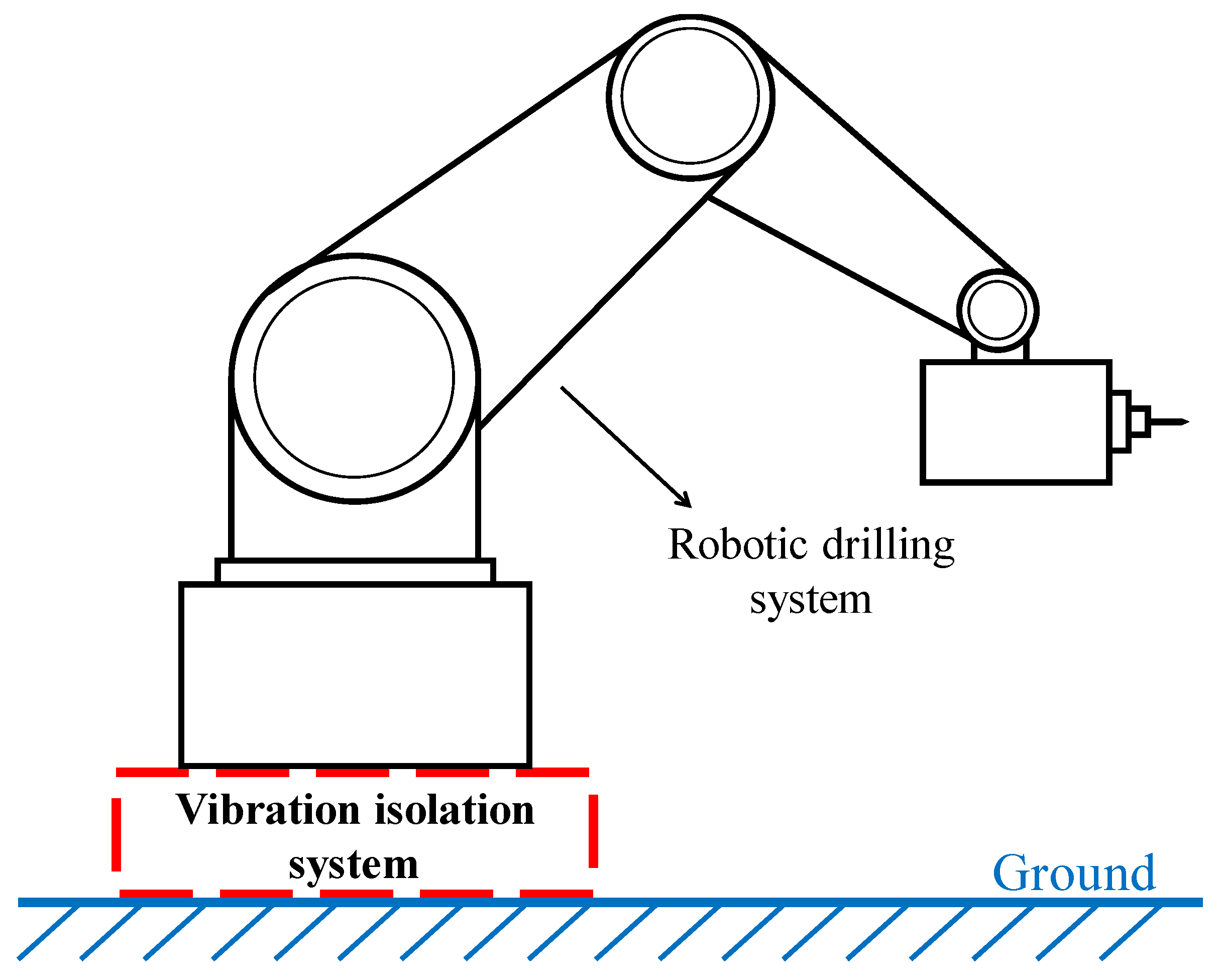
Figure 1. Robotic drilling system model.
Machines 09 00067 g001
Figure 2. Model of a variable stiffness quasi-zero stiffness vibration control system (1—load platform; 2—linear guide block; 3—bearing spring; 4—linear guide rail; 5—base; 6—linear guide module; 7—buffer spring; 8—driving block; 9—horizontal spring; 10—damper; 11—connecting rod).
Machines 09 00067 g002
Figure 3. Schematic diagram of the passive vibration control system.
Machines 09 00067 g003
Figure 4. Dynamic stiffness curves for α = 1, λ1 = 0.8 with λ2.
Machines 09 00067 g004
Figure 5. Dynamic stiffness curves for α = 1, λ2 = 1.4 with λ1.
Machines 09 00067 g005
Figure 6. Dynamic stiffness curves for λ1 = 0.8, λ2 = 1.4 with α.
Machines 09 00067 g006
Figure 7. Schematic diagram of the quasi-zero stiffness vibration isolation system.
Machines 09 00067 g007
Figure 8. Amplitude–frequency characteristics and stability curves.
Machines 09 00067 g008
Figure 9. Effect of stiffness ratio on transmissibility.
Machines 09 00067 g009
Figure 10. Effect of damping coefficient on transmissibility.
Machines 09 00067 g010
Figure 11. Effect of the damping coefficient on transmissibility.
Machines 09 00067 g011
Figure 12. Realization of input stiffness by the actuator.
Machines 09 00067 g012
Figure 13. Effect of the damping coefficient on critical amplitude.
Machines 09 00067 g013
Figure 14. Fit curves. ((a) Fitting curves of first-, third- and fourth-order polynomials (b) Residual analysis).
Machines 09 00067 g014
Figure 15. Simulation operation interface. (a) Structural design interface. (b) Analysis interface.
Machines 09 00067 g015
Figure 16. Time domain response of the variable stiffness system.
Machines 09 00067 g016
Figure 17. Time domain response of variable stiffness and damping system.
Machines 09 00067 g017
Table 1. Simulation parameters.
NameValue
Mass M300 kg
Stiffness of horizontal spring Kh27 N/mm
Stiffness of vertical spring Kv30 N/mm
Vertical damping coefficient c0.12 N·s/mm
Connecting rod length a160 mm
Original length of horizontal spring L0200 mm
Configurative parameter d280 mm
Excitation amplitude Z1 mm
Publisher’s Note: MDPI stays neutral with regard to jurisdictional claims in published maps and institutional affiliations.