
Fischer-Tropsch Diesel and Biofuels Exergy and Energy Analysis for Low Emissions Vehicles

 ,
,  ,
,  ,
,  and
and 
Abstract
:1. Introduction

| Ref. | Year | Engine Characteristics | Operating Conditions | Fuel Type | Energy Efficiency (%) | Exergy Efficiency (%) | Outcomes |
|---|---|---|---|---|---|---|---|
| [26] | 2016 | 1-cylinder 4 stroke Antor 3LD510 | 12 different speeds (1000–3000 rpm) Full load | Diesel D75-92/B10-20/E5 | 27.18–31.42 @ 1400 rpm 24.13–27.62 @ 2800 rpm | 25.37–29.34 @ 1400 rpm 22.53–25.82 @ 2800 rpm | ↑ speed ↓ efficiency ηdiesel > ηblends ψdiesel > ψblends |
| [29] | 2016 | 4-cylinders 4 stroke OM 314 Euro II | 5 speeds 5 loads | Diesel D50-78/B0-40/E0-16 | n/a | 25.21–32.88 @ 40% load 31.68–24.20 @ 80% load | ↑ speed ↓ efficiency ↑ load ↑ efficiency |
| [30] | 2017 | 1-cylinder 4 stroke Kirloskar TV-1 | 1500 rpm 6 loads (20–120%) | Diesel D30-45/B50/E5-20 | 23.49–27.05 @ 80% load 25.33–32.19 @ 100% load | 20.91–24.49 @ 80% load 23.29–29.32 @ 100% load | ↑ load ↑ efficiency ηD35/E15/B50 > ηdiesel ψD35/E15/B50 > ψdiesel |
| [31] | 2019 | 4-cylinders 4 stroke Yangdong Y85 | 1600 rpm Full load | Diesel D41-78/B17-49/E5-10 | 25.82–27.08 | n/a | ηdiesel > ηblends |
| [32] | 2019 | 1-cylinder 4 stroke Kirloskar TAF1 | 1500 rpm 5 loads | Diesel D90-98/B1.5-7.5/E0.5-2.5 | 19.25–21.24 @ 40% load 22.73–32.77 @ full load | 21.45–28.21 @ full load | ↑ load ↑ efficiency ηD90/B7.5/E2.5 > ηdiesel ψD90/B7.5/E2.5 > ψdiesel |
| [33] | 2020 | 6-cylinders 4 stroke Scania DC 1102 | 1450 rpm 5 loads (3–92%) | GTL GTL25-75/B25-75 | 14.65–15.05 @ 3% load 43.93–45.27 @ 92% load | 13.70–14.08 @ 3% load 41.12–41.65 @ 92% load | ↑ load ↑ efficiency ηGTL25/B75 > ηGTL ψGTL25/B75 > ψGTL |
| [34] | 2020 | 1-cylinder 4 stroke NSB-8.18 | 1900 rpm 2 loads | Diesel D82/B10/E8 | 21.9–22.0 @ 5.71 kW 22.6–22.9 @ 7.43 kW | n/a | ↑ load ↑ efficiency ηdiesel > ηD82/B10/E8 |
| [27] | 2020 | 1-cylinder 4 stroke | 2 speeds Full load | Diesel D60-75/B20/But5-20 | 30.17–31.92 @ 1400 rpm 26.91–27.83 @ 2800 rpm | 28.13–29.77 @ 1400 rpm 25.03–25.96 @ 2800 rpm | ↑ speed ↓ efficiency ηdiesel > ηblends ψdiesel > ψblends |
2. Materials and Methods
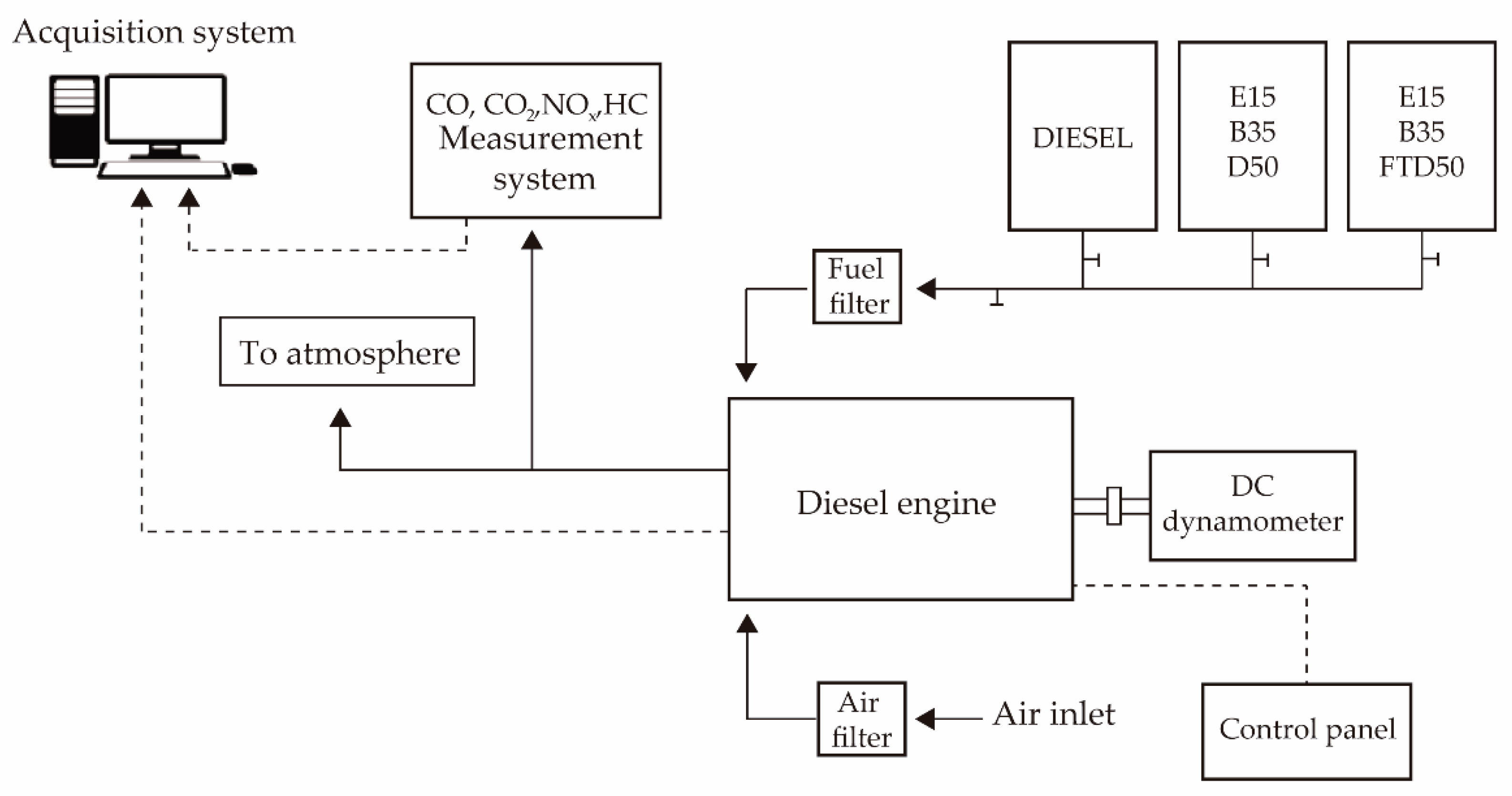
2.1. Experimental Setup
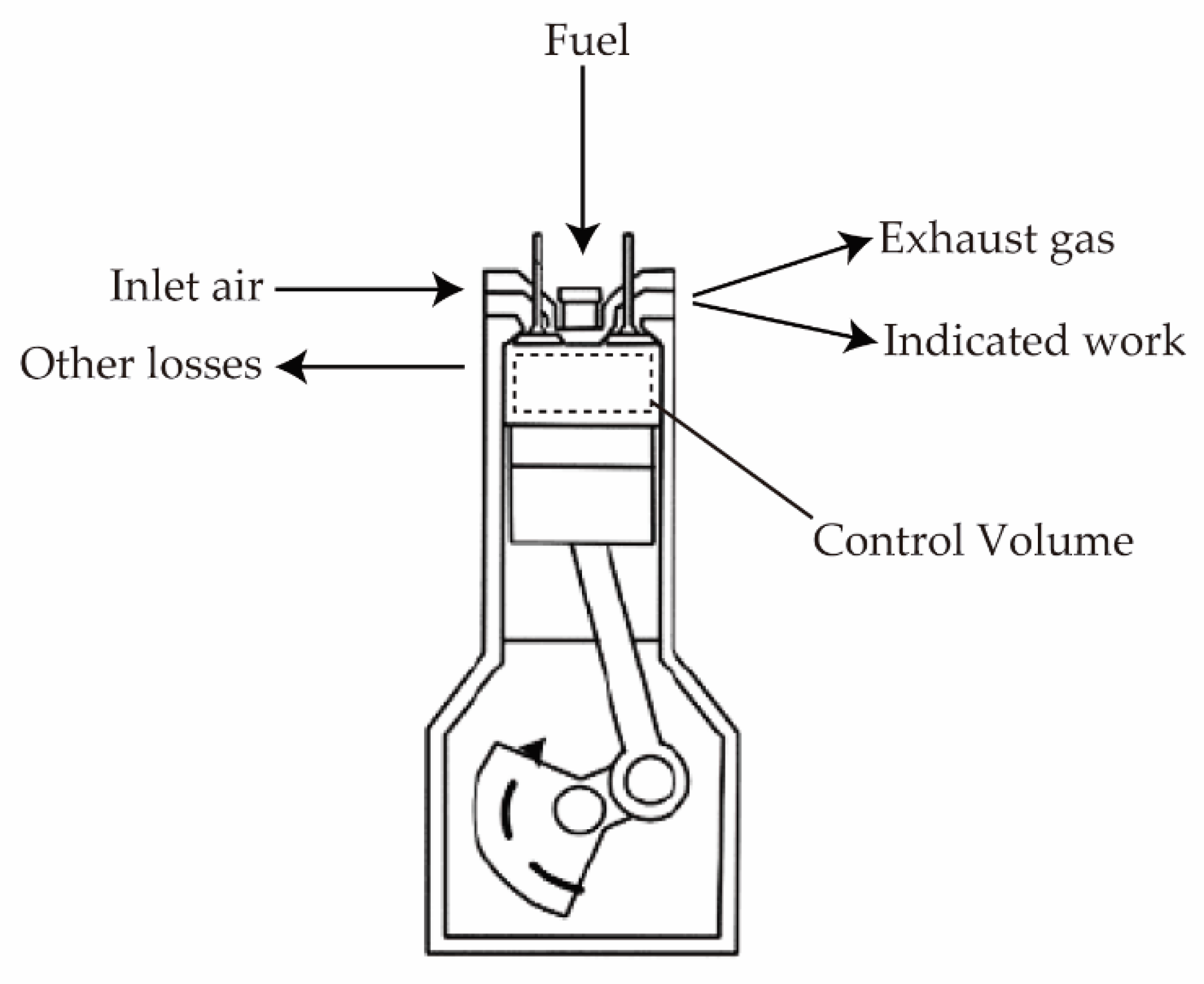
2.2. Thermodynamic Analysis
- The engine operation is studied at the steady-state condition;
- The intake air and the outlet exhaust gases were considered as mixtures of ideal gases;
- The environment (reference state) was considered at T0 = 25 °C and P0 = 101.325 kPa and did not vary with time;
- The kinetic and potential energy effects of incoming fluid streams and outgoing fluid streams were neglected [44].
2.2.1. Energy Analysis
2.2.2. Exergy Analysis
3. Results and Discussions
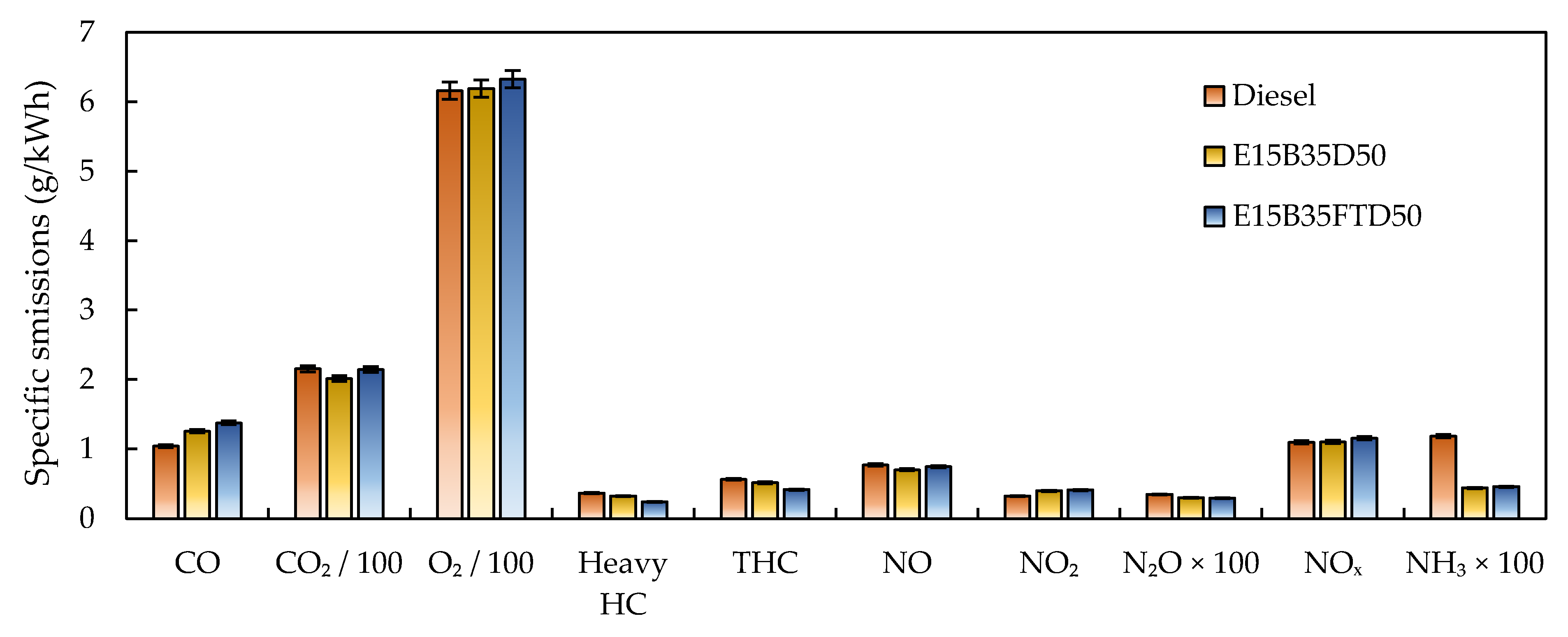
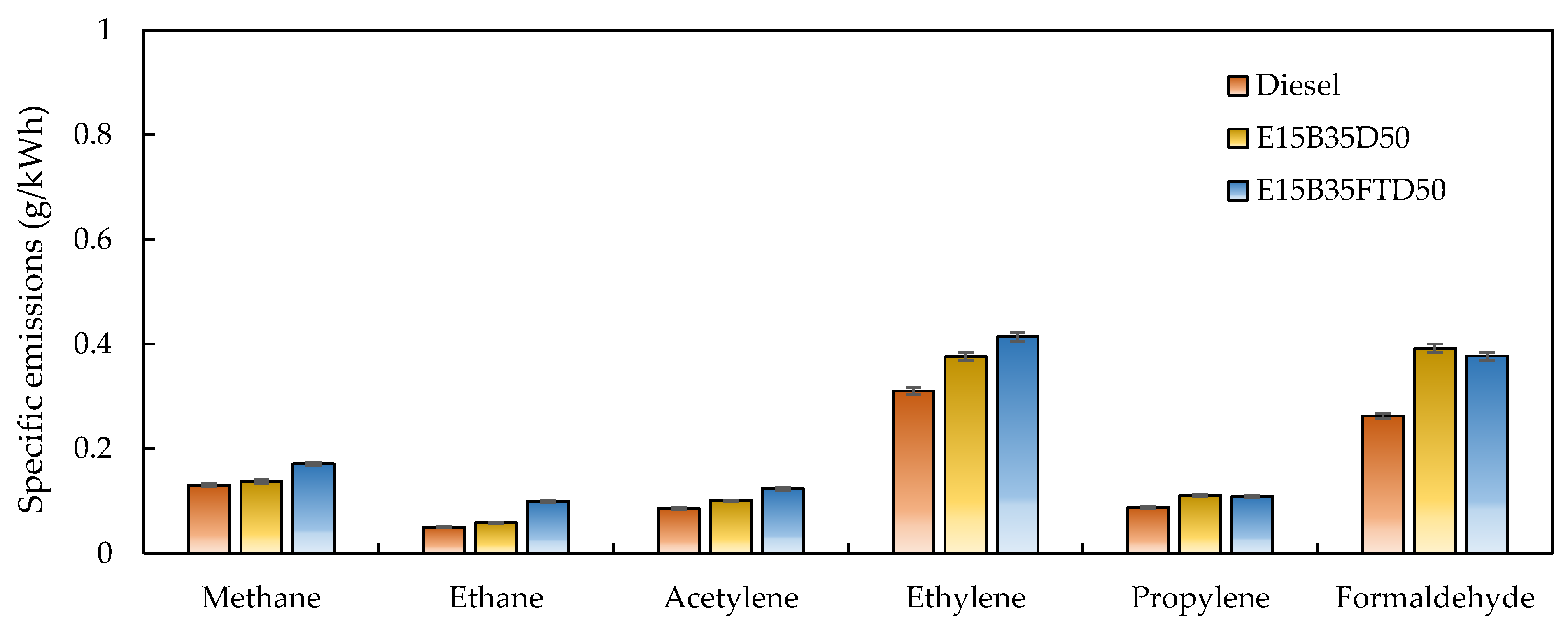
3.1. Gaseous Emissions
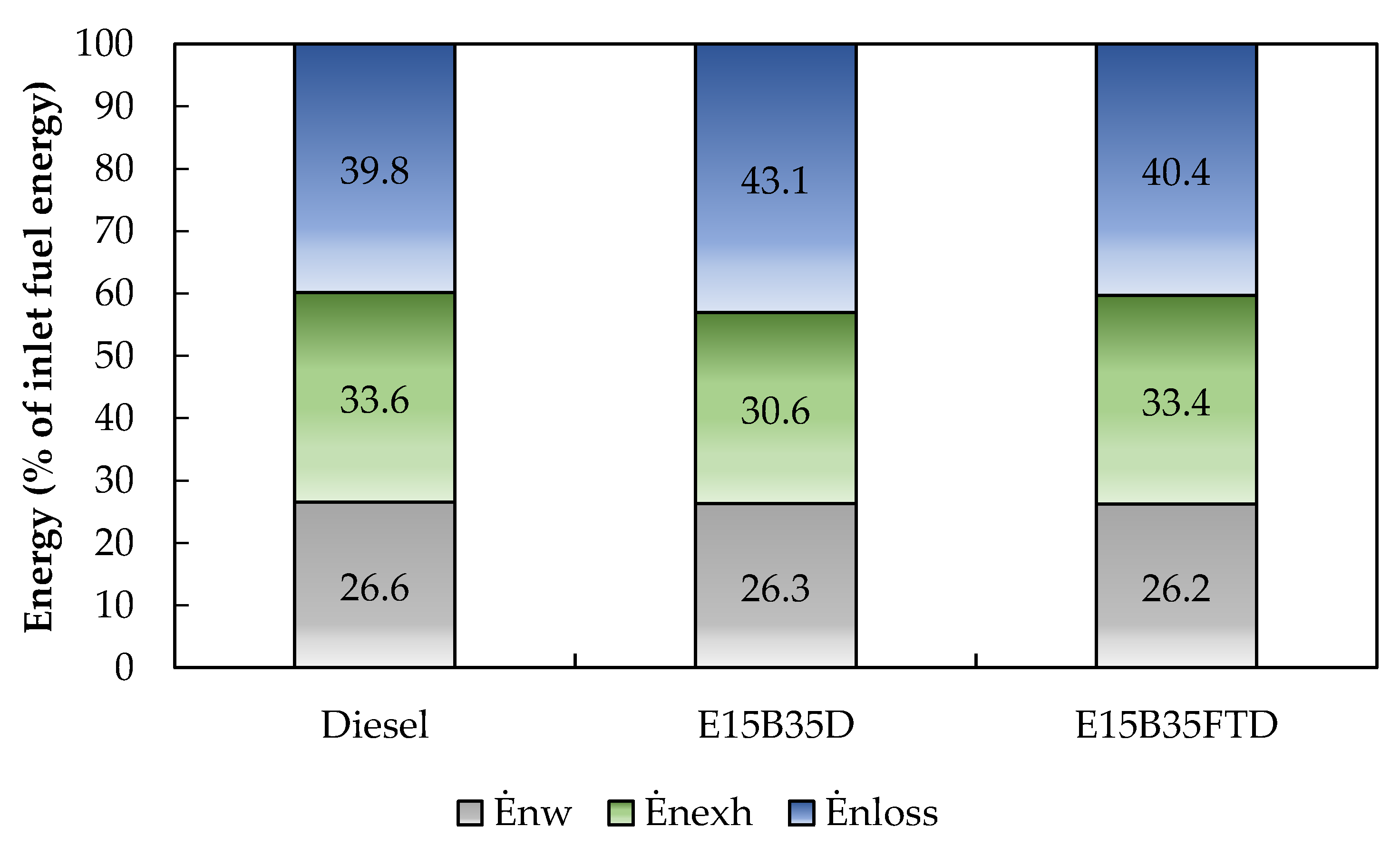
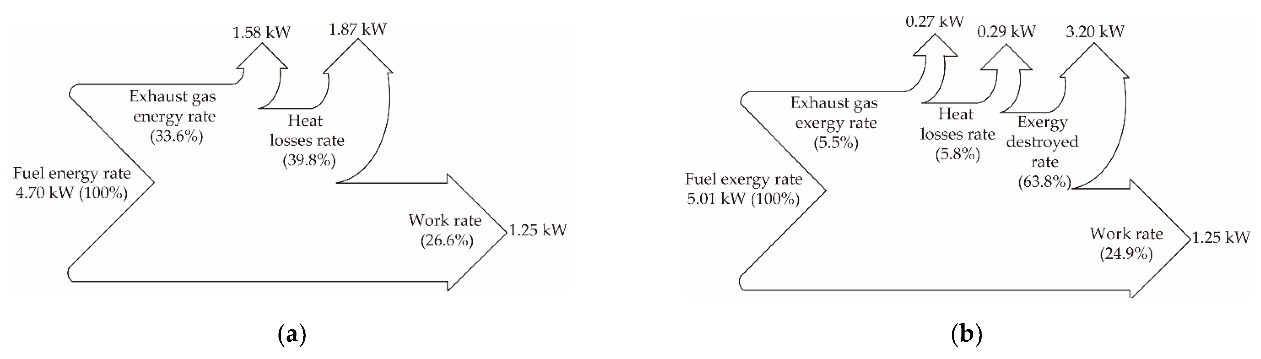
3.2. Energy Analysis
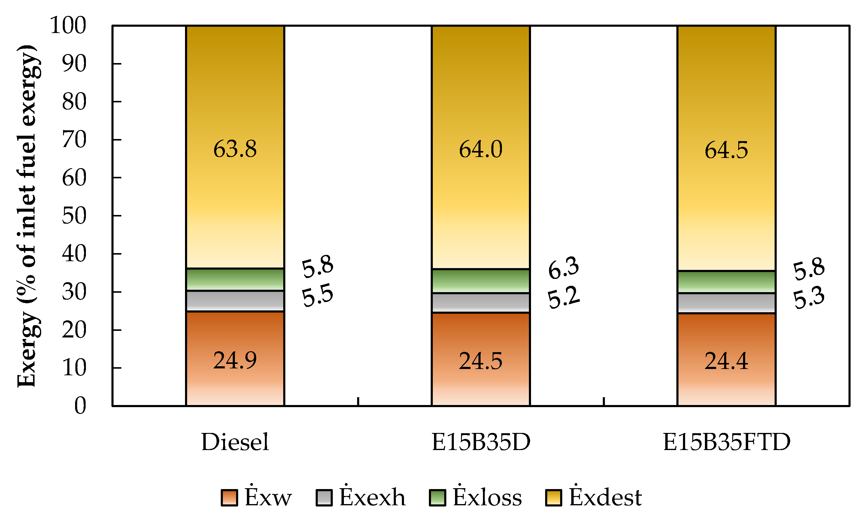
3.3. Exergy Analysis
4. Conclusions
Author Contributions
Funding
Institutional Review Board Statement
Informed Consent Statement
Data Availability Statement
Acknowledgments
Conflicts of Interest
Abbreviations
| BTL | Biomass-to-liquid |
| bTDC | Before the top dead center |
| C2H2 | Acetylene |
| C2H4 | Ethylene |
| C2H6 | Ethane |
| C3H6 | Propylene |
| C3H8 | Propane |
| CH2O | Formaldehyde |
| CH4 | Methane |
| CI | Compression ignition |
| CO | Carbon monoxide |
| CO2 | Carbon dioxide |
| E15B35D50 | 15% ethanol, 35% biodiesel, 50% diesel |
| E15B35FTD50 | 15% ethanol, 35% biodiesel, 50% Fischer-Tropsch diesel |
| FID | Flame ionization detector |
| F-T | Fischer-Tropsch |
| FTD | Fischer-Tropsch diesel |
| FTIR | Fourier transform infrared |
| GTL | Gas-to-liquid |
| HC | Hydrocarbons |
| HEV | Hybrid electric vehicles |
| ICE | Internal combustion engines |
| IMEP | Indicated mean effective pressure |
| LHV | Lower heating value |
| N2O | Nitrous oxide |
| NH3 | Ammonia |
| NO | Nitrogen oxige |
| NO2 | Nitrogen dioxide |
| NOx | Nitrogen oxides |
| PCIS | Pre-chamber ignition system |
| PM | Particulate matter |
| RCCI | Reactivity-controlled compression ignition |
| SI | Sustainability index |
| TDC | Top dead center |
| THC | Total hydrocarbons |
| Symbols | |
| energy rate, W | |
| exergy rate, W | |
| specific exergy, J/kg or J/mol | |
| h | enthalpy, J/kg or J/mol |
| mass flow rate, kg/s | |
| molar flow rate, mol/s | |
| N | engine speed, rpm |
| nR | number of crank revolutions for each power stroke per cylinder, - |
| P | absolute pressure, Pa |
| T | temperature, °C or K |
| Vd | displaced volume, m3 |
| R | universal gas constant, J/kg·K or J/mol·K |
| s | entropy, J/kg·K or J/mol·K |
| Entropy rate, W | |
| x | molar fraction, - |
| Subscripts | |
| 0 | reference state |
| ch | chemical |
| cool | coolant |
| dest | destruction |
| exh | exhaust |
| gen | generation |
| i | individual gaseous species |
| in | inlet |
| out | outlet |
| ph | physical |
| W | work |
| Greek sumbols | |
| activity coefficiency, - | |
| standard chemical exergy, J/mol | |
| energy efficiency, - | |
| chemical exergy factor, - | |
| ψ | exergy efficiency, - |
References
- Correa, G.; Muñoz, P.M.; Rodriguez, C.R. A Comparative Energy and Environmental Analysis of a Diesel, Hybrid, Hydrogen and Electric Urban Bus. Energy 2019, 187, 115906. [Google Scholar] [CrossRef]
- Serrano, J.R.; Novella, R.; Piqueras, P. Why the Development of Internal Combustion Engines Is Still Necessary to Fight against Global Climate Change from the Perspective of Transportation. Appl. Sci. 2019, 9, 4597. [Google Scholar] [CrossRef] [Green Version]
- Dranka, G.G.; Ferreira, P. Electric Vehicles and Biofuels Synergies in the Brazilian Energy System. Energies 2020, 13, 4423. [Google Scholar] [CrossRef]
- Paredes Rojas, J.C.; Torres San Miguel, C.R.; Vázquez Medina, R.; Leal Naranjo, J.A.; Ortiz Hernàndez, F.E.; Costa Castelló, R. Pollutant Emissions and Combustion Efficiency Assessment of Engines Using Biodiesel. Appl. Sci. 2020, 10, 8646. [Google Scholar] [CrossRef]
- Beatrice, C.; Denbratt, I.; Di Blasio, G.; Di Luca, G.; Ianniello, R.; Saccullo, M. Experimental Assessment on Exploiting Low Carbon Ethanol Fuel in a Light-Duty Dual-Fuel Compression Ignition Engine. Appl. Sci. 2020, 10, 7182. [Google Scholar] [CrossRef]
- Shi, J.; Wang, T.; Zhao, Z.; Wu, Z.; Zhang, Z. Cycle-to-Cycle Variation of a Diesel Engine Fueled with Fischer-Tropsch Fuel Synthesized from Coal. Appl. Sci. 2019, 9, 2032. [Google Scholar] [CrossRef] [Green Version]
- Mahmoudi, H.; Jahangiri, H.; Doustdar, O.; Akbari, N.; Wood, J.; Tsolakis, A.; Wyszynski, M.L. Maximizing Paraffin to Olefin Ratio Employing Simulated Nitrogen-Rich Syngas via Fischer-Tropsch Process over Co3O4/SiO2 Catalysts. Fuel Process. Technol. 2020, 208, 106477. [Google Scholar] [CrossRef]
- OECD/FAO. OECD-FAO Agricultural Outlook 2019–2028; OECD: Paris, France, 2019. [Google Scholar]
- Çelebi, Y.; Aydın, H. An Overview on the Light Alcohol Fuels in Diesel Engines. Fuel 2019, 236, 890–911. [Google Scholar] [CrossRef]
- Mendes Guedes, A.D.; Leal Braga, S.; Pradelle, F. Performance and Combustion Characteristics of a Compression Ignition Engine Running on Diesel-Biodiesel-Ethanol (DBE) Blends—Part 2: Optimization of Injection Timing. Fuel 2018, 225, 174–183. [Google Scholar] [CrossRef]
- Emiroğlu, A.O.; Şen, M. Combustion, Performance and Exhaust Emission Characterizations of a Diesel Engine Operating with a Ternary Blend (Alcohol-Biodiesel-Diesel Fuel). Appl. Therm. Eng. 2018, 133, 371–380. [Google Scholar] [CrossRef]
- Valencia Ochoa, G.; Acevedo Peñaloza, C.; Duarte Forero, J. Combustion and Performance Study of Low-Displacement Compression Ignition Engines Operating with Diesel–Biodiesel Blends. Appl. Sci. 2020, 10, 907. [Google Scholar] [CrossRef] [Green Version]
- Choi, K.; Park, S.; Roh, H.G.; Lee, C.S. Combustion and Emission Reduction Characteristics of GTL-Biodiesel Fuel in a Single-Cylinder Diesel Engine. Energies 2019, 12, 2201. [Google Scholar] [CrossRef] [Green Version]
- Venu, H.; Raju, V.D.; Lingesan, S.; Soudagar, M.E.M. Influence of Al2O3nano Additives in Ternary Fuel (Diesel-Biodiesel-Ethanol) Blends Operated in a Single Cylinder Diesel Engine: Performance, Combustion and Emission Characteristics. Energy 2021, 215, 119091. [Google Scholar] [CrossRef]
- Glensor, K.; Muñoz B., M.R. Life-Cycle Assessment of Brazilian Transport Biofuel and Electrification Pathways. Sustainability 2019, 11, 6332. [Google Scholar] [CrossRef] [Green Version]
- García, A.; Monsalve-Serrano, J.; Martínez-Boggio, S.; Roso, V.R.; Santos, N.D.S.A. Potential of Bio-Ethanol in Different Advanced Combustion Modes for Hybrid Passenger Vehicles. Renew. Energy 2020, 150, 58–77. [Google Scholar] [CrossRef]
- García, A.; Monsalve-Serrano, J. Analysis of a Series Hybrid Vehicle Concept That Combines Low Temperature Combustion and Biofuels as Power Source. Results Eng. 2019, 1, 100001. [Google Scholar] [CrossRef]
- Kumar, P.; Sandhu, S.S. Impact Analysis of Partially Premixed Combustion Strategy on the Emissions of a Compression Ignition Engine Fueled with Higher Octane Number Fuels: A Review. Mater. Today Proc. 2021, 45, 5772–5777. [Google Scholar] [CrossRef]
- Macián, V.; Monsalve-Serrano, J.; Villalta, D.; Fogué-Robles, Á. Extending the Potential of the Dual-Mode Dual-Fuel Combustion towards the Prospective EURO VII Emissions Limits Using Gasoline and OMEx. Energy Convers. Manag. 2021, 233, 113927. [Google Scholar] [CrossRef]
- di Blasio, G.; Vassallo, A.; Pesce, F.C.; Beatrice, C.; Belgiorno, G.; Avolio, G. The Key Role of Advanced, Flexible Fuel Injection Systems to Match the Future CO2 Targets in an Ultra-Light Mid-Size Diesel Engine. SAE Int. J. Engines 2019, 12, 129–144. [Google Scholar] [CrossRef]
- Yesilyurt, M.K.; Arslan, M. Analysis of the Fuel Injection Pressure Effects on Energy and Exergy Efficiencies of a Diesel Engine Operating with Biodiesel. Biofuels 2019, 10, 643–655. [Google Scholar] [CrossRef]
- da Silva, J.A.M.; Seifert, V.; de Morais, V.O.B.; Tsolakis, A.; Herreros, J.; Torres, E. Exergy Evaluation and ORC Use as an Alternative for Efficiency Improvement in a CI-Engine Power Plant. Sustain. Energy Technol. Assess. 2018, 30, 216–223. [Google Scholar] [CrossRef]
- Sun, W.; Liu, Z. Parametric Assessment on the Advanced Exergy Performance of a CO2 Energy Storage Based Trigeneration System. Appl. Sci. 2020, 10, 8341. [Google Scholar] [CrossRef]
- Dogan, B.; Cakmak, A.; Yesilyurt, M.K.; Erol, D. Investigation on 1-Heptanol as an Oxygenated Additive with Diesel Fuel for Compression-Ignition Engine Applications: An Approach in Terms of Energy, Exergy, Exergoeconomic, Enviroeconomic, and Sustainability Analyses. Fuel 2020, 275, 117973. [Google Scholar] [CrossRef]
- Karagoz, M.; Uysal, C.; Agbulut, U.; Saridemir, S. Exergetic and Exergoeconomic Analyses of a CI Engine Fueled with Diesel-Biodiesel Blends Containing Various Metal-Oxide Nanoparticles. Energy 2021, 214, 118830. [Google Scholar] [CrossRef]
- Kul, B.S.; Kahraman, A. Energy and Exergy Analyses of a Diesel Engine Fuelled with Biodiesel-Diesel Blends Containing 5% Bioethanol. Entropy 2016, 18, 387. [Google Scholar] [CrossRef]
- Sarıkoç, S.; Örs, İ.; Ünalan, S. An Experimental Study on Energy-Exergy Analysis and Sustainability Index in a Diesel Engine with Direct Injection Diesel-Biodiesel-Butanol Fuel Blends. Fuel 2020, 268, 117321. [Google Scholar] [CrossRef]
- Fayad, M.A.; Fernàndez-Rodríguez, D.; Herreros, J.M.; Lapuerta, M.; Tsolakis, A. Interactions between Aftertreatment Systems Architecture and Combustion of Oxygenated Fuels for Improved Low Temperature Catalysts Activity. Fuel 2018, 229, 189–197. [Google Scholar] [CrossRef] [Green Version]
- Khoobbakht, G.; Akram, A.; Karimi, M.; Najafi, G. Exergy and Energy Analysis of Combustion of Blended Levels of Biodiesel, Ethanol and Diesel Fuel in a DI Diesel Engine. Appl. Therm. Eng. 2016, 99, 720–729. [Google Scholar] [CrossRef]
- Paul, A.; Panua, R.; Debroy, D. An Experimental Study of Combustion, Performance, Exergy and Emission Characteristics of a CI Engine Fueled by Diesel-Ethanol-Biodiesel Blends. Energy 2017, 141, 839–852. [Google Scholar] [CrossRef]
- Krishna, S.M.; Abdul Salam, P.; Tongroon, M.; Chollacoop, N. Performance and Emission Assessment of Optimally Blended Biodiesel-Diesel-Ethanol in Diesel Engine Generator. Appl. Therm. Eng. 2019, 155, 525–533. [Google Scholar] [CrossRef]
- Kavitha, K.R.; Jayaprabakar, J.; Prabhu, A. Exergy and Energy Analyses on Biodiesel–Diesel-Ethanol Blends in a Diesel Engine. Int. J. Ambient. Energy 2019, 0750, 1–5. [Google Scholar] [CrossRef]
- Nabi, M.N.; Hustad, J.E.; Arefin, M.A. The Influence of Fischer–Tropsch-Biodiesel–Diesel Blends on Energy and Exergy Parameters in a Six-Cylinder Turbocharged Diesel Engine. Energy Rep. 2020, 6, 832–840. [Google Scholar] [CrossRef]
- Ferreira, V.P.; Torres, E.A.; da Silva, J.A.M.; Silva, L.F. Evaluation of Ethanol as Additive for NOx and PM Reduction in CI Engines Fueled with Diesel–Biodiesel Blends Using a Pump Assembly. J. Braz. Soc. Mech. Sci. Eng. 2020, 42, 408. [Google Scholar] [CrossRef]
- Fayad, M.A.; Tsolakis, A.; Martos, F.J. Influence of Alternative Fuels on Combustion and Characteristics of Particulate Matter Morphology in a Compression Ignition Diesel Engine. Renew. Energy 2020, 149, 962–969. [Google Scholar] [CrossRef]
- Fayad, M.A.; Herreros, J.M.; Martos, F.J.; Tsolakis, A. Role of Alternative Fuels on Particulate Matter (PM) Characteristics and Influence of the Diesel Oxidation Catalyst. Environ. Sci. Technol. 2015, 49, 11967–11973. [Google Scholar] [CrossRef] [Green Version]
- Soloiu, V.; Gaubert, R.; Moncada, J.; Wiley, J.; Williams, J.; Harp, S.; Ilie, M.; Molina, G.; Mothershed, D. Reactivity Controlled Compression Ignition and Low Temperature Combustion of Fischer-Tropsch Fuel Blended with n-Butanol. Renew. Energy 2019, 134, 1173–1189. [Google Scholar] [CrossRef]
- Herreros, J.M.; Schroer, K.; Sukjit, E.; Tsolakis, A. Extending the Environmental Benefits of Ethanol–Diesel Blends through DGE Incorporation. Appl. Energy 2015, 146, 335–343. [Google Scholar] [CrossRef] [Green Version]
- Serhan, N.; Tsolakis, A.; Wahbi, A.; Martos, F.J.; Golunski, S. Modifying Catalytically the Soot Morphology and Nanostructure in Diesel Exhaust: Influence of Silver De-NOx Catalyst (Ag/Al2O3). Appl. Catal. B Environ. 2019, 241, 471–482. [Google Scholar] [CrossRef]
- Moran, M.J.; Shapiro, H.N.; Boettner, D.D.; Bailey, M.B. Fundamentals of Engineering Thermodynamics, 9th ed.; Wiley: Hoboken, NJ, USA, 2018; ISBN 978-1-119-39138-8. [Google Scholar]
- Kotas, T.J. The Exergy Method of Thermal Plant Analysis; Elsevier: Amsterdam, The Netherlands, 1985; ISBN 0-408-01350-8. [Google Scholar]
- Szargut, J. Exergy Method: Technical and Ecological Applications; WIT Press: Southampton, UK, 2005; ISBN 978-1-85312-753-3. [Google Scholar]
- Dincer, I.; Bicer, Y. Exergy: Energy, Environment and Sustainable Development, 2nd ed.; Elsevier Science: Amsterdam, The Netherlands, 2013; ISBN 978-0-08-097089-9. [Google Scholar]
- Karagoz, M.; Uysal, C.; Agbulut, U.; Saridemir, S. Energy, Exergy, Economic and Sustainability Assessments of a Compression Ignition Diesel Engine Fueled with Tire Pyrolytic Oil—Diesel Blends. J. Clean. Prod. 2020, 264, 121724. [Google Scholar] [CrossRef]
- Sayin, C.; Hosoz, M.; Canakci, M.; Kilicaslan, I. Energy and Exergy Analyses of a Gasoline Engine. Int. J. Energy Res. 2007, 31, 259–273. [Google Scholar] [CrossRef]
- Caliskan, H.; Mori, K. Environmental, Enviroeconomic and Enhanced Thermodynamic Analyses of a Diesel Engine with Diesel Oxidation Catalyst (DOC) and Diesel Particulate Filter (DPF) after Treatment Systems. Energy 2017, 128, 128–144. [Google Scholar] [CrossRef]
- Verma, S.; Das, L.M.; Kaushik, S.C.; Tyagi, S.K. An Experimental Investigation of Exergetic Performance and Emission Characteristics of Hydrogen Supplemented Biogas-Diesel Dual Fuel Engine. Int. J. Hydrogen Energy 2018, 43, 2452–2468. [Google Scholar] [CrossRef]
- Tat, M.E. Cetane Number Effect on the Energetic and Exergetic Efficiency of a Diesel Engine Fuelled with Biodiesel. Fuel Process. Technol. 2011, 92, 1311–1321. [Google Scholar] [CrossRef]
- Rosen, M.A.; Dincer, I.; Kanoglu, M. Role of Exergy in Increasing Efficiency and Sustainability and Reducing Environmental Impact. Energy Policy 2008, 36, 128–137. [Google Scholar] [CrossRef]
- Andrade Torres, F.; Doustdar, O.; Herreros, J.M.; Li, R.; Poku, R.; Tsolakis, A.; Martins, J.; Vieira de Melo, S.A.B. A Comparative Study of Biofuels and Fischer–Tropsch Diesel Blends on the Engine Combustion Performance for Reducing Exhaust Gaseous and Particulate Emissions. Energies 2021, 14, 1538. [Google Scholar] [CrossRef]
- Ghadikolaei, M.A.; Cheung, C.S.; Yung, K.-F. Study of Combustion, Performance and Emissions of Diesel Engine Fueled with Diesel/Biodiesel/Alcohol Blends Having the Same Oxygen Concentration. Energy 2018, 157, 258–269. [Google Scholar] [CrossRef]
- Carvalho, M.; Torres, F.; Ferreira, V.; Silva, J.; Martins, J.; Torres, E. Effects of Diethyl Ether Introduction in Emissions and Performance of a Diesel Engine Fueled with Biodiesel-Ethanol Blends. Energies 2020, 13, 3787. [Google Scholar] [CrossRef]
- Heidari-Maleni, A.; Gundoshmian, T.M.; Karimi, B.; Jahanbakhshi, A.; Ghobadian, B. A Novel Fuel Based on Biocompatible Nanoparticles and Ethanol-Biodiesel Blends to Improve Diesel Engines Performance and Reduce Exhaust Emissions. Fuel 2020, 276, 118079. [Google Scholar] [CrossRef]
- Mofijur, M.; Rasul, M.G.; Hyde, J.; Azad, A.K.; Mamat, R.; Bhuiya, M.M.K. Role of Biofuel and Their Binary (Diesel-Biodiesel) and Ternary (Ethanol-Biodiesel-Diesel) Blends on Internal Combustion Engines Emission Reduction. Renew. Sustain. Energy Rev. 2016, 53, 265–278. [Google Scholar] [CrossRef] [Green Version]
- Guarieiro, L.L.N.; de Souza, A.F.; Torres, E.A.; de Andrade, J.B. Emission Profile of 18 Carbonyl Compounds, CO, CO2, and NOx Emitted by a Diesel Engine Fuelled with Diesel and Ternary Blends Containing Diesel, Ethanol and Biodiesel or Vegetable Oils. Atmos. Environ. 2009, 43, 2754–2761. [Google Scholar] [CrossRef]
- de Carvalho, M.A.S.; Achy, A.R.A.; Junior, L.C.S.S.; Ferreira, V.P.; da Silva, J.A.M.; Pepe, I.M.; Torres, E.A. Mechanical and Emissions Performance of a Diesel Engine Fueled with Biodiesel, Ethanol and Diethyl Ether Blends. J. Braz. Soc. Mech. Sci. Eng. 2020, 42, 182. [Google Scholar] [CrossRef]
- Khan, M.; Tafreshi, R.; Mokahal, A.J.; Mohamed, M.T.; Hanbal, M.Y.; Elturk, J. Single Cylinder GTL ENGINE: An Experimental Comparison between Traditional Diesel and GTL Diesel on Single Cylinder Engine; SAE Technical Papers; SAE International: Warrendale, PA, USA, 5 April 2016. [Google Scholar]
- Gill, S.S.; Tsolakis, A.; Dearn, K.D.; Rodríguez-Fernández, J. Combustion Characteristics and Emissions of Fischer–Tropsch Diesel Fuels in IC Engines. Prog. Energy Combust. Sci. 2011, 37, 503–523. [Google Scholar] [CrossRef]
- Soriano, J.A.; García-Contreras, R.; Leiva-Candia, D.; Soto, F. Influence on Performance and Emissions of an Automotive Diesel Engine Fueled with Biodiesel and Paraffinic Fuels: GTL and Biojet Fuel Farnesane. Energy Fuels 2018, 32, 5125–5133. [Google Scholar] [CrossRef]
- Ye, L.; Shi, Y.; Liu, T.; Zheng, Q.; Ashfaq, M.M.; Sun, C.; Shi, A.; Ajmal, M. Study on Emission and Particulate Matter Characteristics from Diesel Engine Fueled with N-Pentanol/Fischer–Tropsch Diesel. Energy Sources Part A Recovery Util. Environ. Eff. 2020, 1–17. [Google Scholar] [CrossRef]
- de Oliveira, A.; Valente, O.S.; Sodré, J.R. Effects of Ethanol Addition to Biodiesel-Diesel Oil Blends (B7 and B20) on Engine Emissions and Fuel Consumption. MRS Adv. 2017, 2, 4005–4015. [Google Scholar] [CrossRef]
- Martins, J.; Torres, F.; Torres, E.; Pimenta, H.; Ferreira, V. The Use of Biodiesel on the Performance and Emission Characteristics of Diesel Engined Vehicles; SAE Technical Papers; SAE International: Warrendale, PA, USA, 2013; Volume 3, pp. 1–8. [Google Scholar]
- Gnanamoorthi, V.; Devaradjane, G. Effect of Compression Ratio on the Performance, Combustion and Emission of DI Diesel Engine Fueled with Ethanol—Diesel Blend. J. Energy Inst. 2015, 88, 19–26. [Google Scholar] [CrossRef]
- Herreros, J.M.; Gill, S.S.; Lefort, I.; Tsolakis, A.; Millington, P.; Moss, E. Enhancing the Low Temperature Oxidation Performance over a Pt and a Pt-Pd Diesel Oxidation Catalyst. Appl. Catal. B Environ. 2014, 147, 835–841. [Google Scholar] [CrossRef] [Green Version]
- Suarez-Bertoa, R.; Mendoza-Villafuerte, P.; Riccobono, F.; Vojtisek, M.; Pechout, M.; Perujo, A.; Astorga, C. On-Road Measurement of NH 3 Emissions from Gasoline and Diesel Passenger Cars during Real World Driving Conditions. Atmos. Environ. 2017, 166, 488–497. [Google Scholar] [CrossRef]
- Yesilyurt, M.K. The Examination of a Compression-Ignition Engine Powered by Peanut Oil Biodiesel and Diesel Fuel in Terms of Energetic and Exergetic Performance Parameters. Fuel 2020, 278, 118319. [Google Scholar] [CrossRef]
- Tutak, W.; Jamrozik, A.; Pyrc, M.; Sobiepański, M. A Comparative Study of Co-Combustion Process of Diesel-Ethanol and Biodiesel-Ethanol Blends in the Direct Injection Diesel Engine. Appl. Therm. Eng. 2017, 117, 155–163. [Google Scholar] [CrossRef]
- Bourhis, G.; Leduc, P. Energy and Exergy Balances for Modern Diesel and Gasoline Engines. Oil Gas Sci. Technol. Rev. De L’institut Français Du Pétrole 2010, 65, 39–46. [Google Scholar] [CrossRef] [Green Version]
- Hoseinpour, M.; Sadrnia, H.; Tabasizadeh, M.; Ghobadian, B. Energy and Exergy Analyses of a Diesel Engine Fueled with Diesel, Biodiesel-Diesel Blend and Gasoline Fumigation. Energy 2017, 141, 2408–2420. [Google Scholar] [CrossRef]
- Jena, J.; Misra, R.D. Effect of Fuel Oxygen on the Energetic and Exergetic Efficiency of a Compression Ignition Engine Fuelled Separately with Palm and Karanja Biodiesels. Energy 2014, 68, 411–419. [Google Scholar] [CrossRef]
- Şanli, B.G. Energetic and Exergetic Performance of a Diesel Engine Fueled with Diesel and Microalgae Biodiesel. Energy Sources Part A Recovery Util. Environ. Eff. 2019, 41, 2519–2533. [Google Scholar] [CrossRef]
- Özcan, H. Energy and Exergy Analyses of Al2O3-Diesel-Biodiesel Blends in a Diesel Engine. Int. J. Exergy 2019, 28, 29. [Google Scholar] [CrossRef]
- Şanli, B.G.; Uludamar, E. Energy and Exergy Analysis of a Diesel Engine Fuelled with Diesel and Biodiesel Fuels at Various Engine Speeds. Energy Sources Part A Recovery Util. Environ. Eff. 2020, 42, 1299–1313. [Google Scholar] [CrossRef]
| Abbreviation | % Volumetric Make-Up | |||||
| Diesel | 100 diesel | |||||
| E15B35D50 | 15 ethanol + 35 biodiesel + 50 diesel | |||||
| E15B35FTD50 | 15 ethanol + 35 biodiesel + 50 F-T diesel | |||||
| Properties | Diesel | Ethanol | Biodiesel | F-T Diesel | E15B35D50 | E15B35FTD50 |
| Chemical formula | C14H26.1 | C2H5OH | C19H35.3O2 | C16.89H35.77 | C14.13H26.88O1.21 | C15.52H31.53O1.24 |
| Cetane number | 53.9 | 8 | 54.7 | 79 | 47.7 (a) | 59.6 a |
| Heat of vaporization [kJ/kg] | 243 | 858 | 216 | 339 [37] | n/a | n/a |
| Lower heating value [MJ/kg] | 43.11 | 26.83 | 37.8 | 43.90 | 38.86 a | 39.13 a |
| Density at 15 °C [kg/m3] | 827.1 | 789.4 | 883.7 | 784.6 | 841.26 b | 820.01 b |
| Aromatics [wt %] | 24.4 | 0 | ~0 | 0.3 | n/a | n/a |
| Theoretical A-F ratio | 14.56: 1 | 10.33: 1 | 11.77: 1 | 14.91: 1 | 12.92: 1 | 13.20: 1 |
| C/H ratio | 6.41 | 3.97 | 6.43 | 5.67 | 6.02 | 5.65 |
| Carbon content [wt %] | 86.47 | 52.14 | 77.15 | 84.91 | 78.06 | 77.28 |
| Hydrogen content [wt %] | 13.53 | 13.13 | 12.03 | 15.09 | 12.94 | 13.72 |
| Oxygen content [wt %] | 0 | 34.73 | 10.82 | 0 | 9.0 | 9.0 |
| Measure | Instrument | Range | Accuracy of the Measurement Range |
|---|---|---|---|
| Exhaust gas (CO, CO2, NOx, THC) | Multigas 2030 FTIR | 10 ppb-100% full scale | ±5% |
| Exhaust gas (O2) | Testo 340 | 0–25% | ±0.2% |
| Crank angle, engine speed | Digital shaft encoder | - | ±1 rev/min |
| In-cylinder pressure | AVL GH13P pressure sensor | 0–250 bar | ±1% |
| Temperature | K-type thermocouples | of 0–1250 °C | ±2.2 °C |
| Fuel | Fuel Energy Rate (kW) | Work Rate (kW) | Exhaust Gas Energy Rate (kW) | Heat Losses Rate (kW) |
|---|---|---|---|---|
| Diesel | 4.70 | 1.25 | 1.58 | 1.87 |
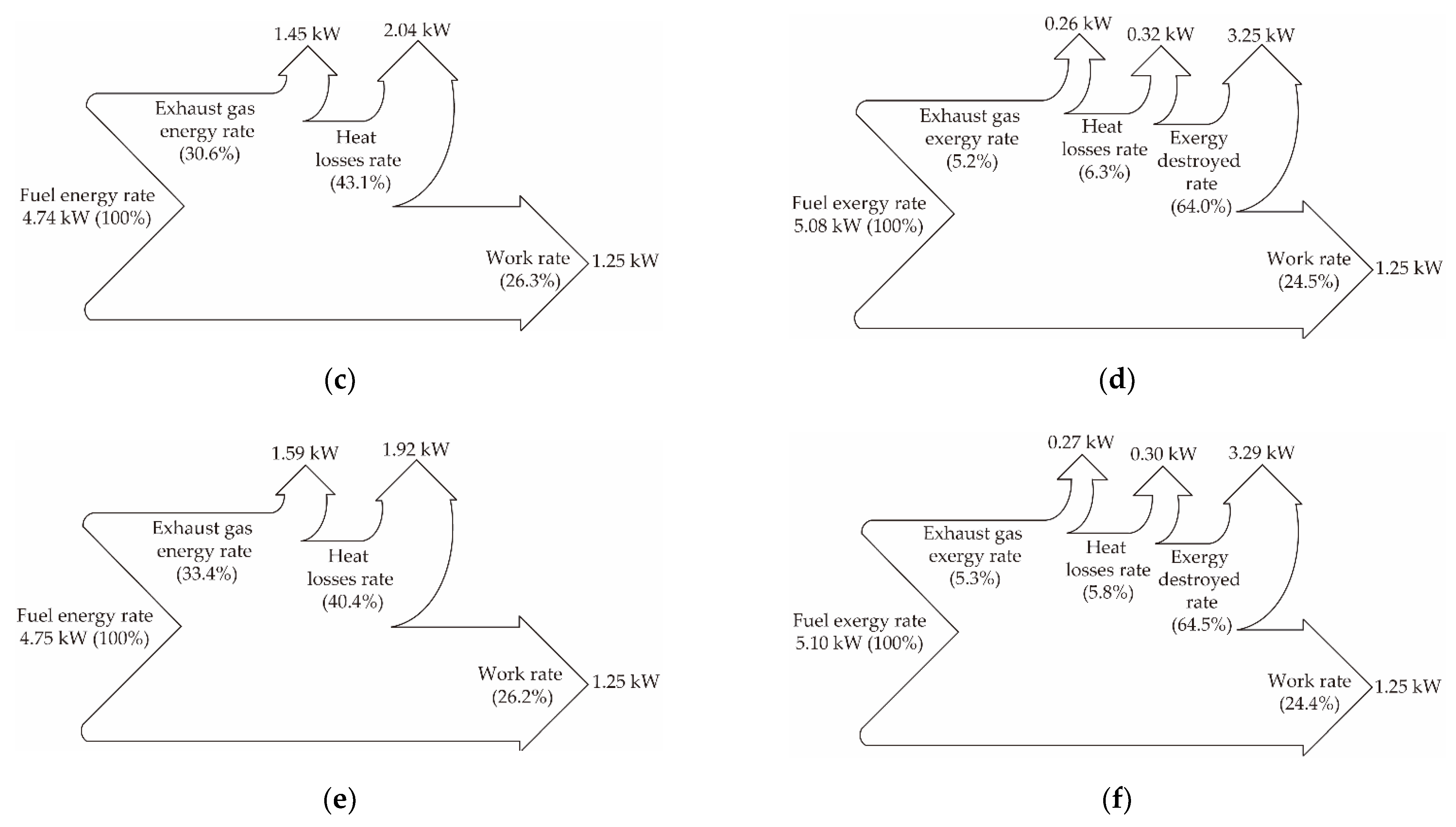
| E15B35D50 | 4.74 | 1.25 | 1.45 | 2.04 |
| E15B35FTD50 | 4.75 | 1.25 | 1.59 | 1.92 |
| Fuel | Fuel Exergy Rate (kW) | Work Rate (kW) | Exhaust Gas Exergy Rate (kW) | Heat Losses Rate (kW) | Exergy Destruction Rate (kW) |
|---|---|---|---|---|---|
| Diesel | 5.01 | 1.25 | 0.28 | 0.29 | 3.20 |
| E15B35D50 | 5.08 | 1.25 | 0.26 | 0.32 | 3.25 |
| E15B35FTD50 | 5.10 | 1.25 | 0.27 | 0.30 | 3.29 |
| Engine Characteristics | Operating Conditions | Fuel Type | Energy Efficiency (%) | Exergy Efficiency (%) | |
|---|---|---|---|---|---|
| 1-cylinder 4 stroke | 1500 rpm 2 bar IMEP (30% load) | Diesel E15/B35/D50 E15/B35/FTD50 | 26.2–26.6 | 24.4–24.9 | ηdiesel > ηblends ψdiesel > ψblends |
Publisher’s Note: MDPI stays neutral with regard to jurisdictional claims in published maps and institutional affiliations. |
© 2021 by the authors. Licensee MDPI, Basel, Switzerland. This article is an open access article distributed under the terms and conditions of the Creative Commons Attribution (CC BY) license (https://creativecommons.org/licenses/by/4.0/).
Share and Cite
Torres, F.A.; Doustdar, O.; Herreros, J.M.; Li, R.; Poku, R.; Tsolakis, A.; Martins, J.; Vieira de Melo, S.A.B. Fischer-Tropsch Diesel and Biofuels Exergy and Energy Analysis for Low Emissions Vehicles. Appl. Sci. 2021, 11, 5958. https://doi.org/10.3390/app11135958
Torres FA, Doustdar O, Herreros JM, Li R, Poku R, Tsolakis A, Martins J, Vieira de Melo SAB. Fischer-Tropsch Diesel and Biofuels Exergy and Energy Analysis for Low Emissions Vehicles. Applied Sciences. 2021; 11(13):5958. https://doi.org/10.3390/app11135958
Chicago/Turabian StyleTorres, Felipe Andrade, Omid Doustdar, Jose Martin Herreros, Runzhao Li, Robert Poku, Athanasios Tsolakis, Jorge Martins, and Silvio A. B. Vieira de Melo. 2021. "Fischer-Tropsch Diesel and Biofuels Exergy and Energy Analysis for Low Emissions Vehicles" Applied Sciences 11, no. 13: 5958. https://doi.org/10.3390/app11135958
APA StyleTorres, F. A., Doustdar, O., Herreros, J. M., Li, R., Poku, R., Tsolakis, A., Martins, J., & Vieira de Melo, S. A. B. (2021). Fischer-Tropsch Diesel and Biofuels Exergy and Energy Analysis for Low Emissions Vehicles. Applied Sciences, 11(13), 5958. https://doi.org/10.3390/app11135958