Article

New Thermal Design Strategy to Achieve an 80-kg-Class Lightweight X-Band Active SAR Small Satellite S-STEP

1
Soletop Co., Ltd., 409 Expo-ro, Yuseong-gu, Daejeon 34051, Korea
2
Satellite System Division, Hanwha System, 304 Cheoin-gu, Yongin City 449-886, Gyeonggi-do, Korea
3
Space Technology Synthesis Laboratory, Department of Smart Vehicle System Engineering, Chosun University (Agency for Defense Development: Additional Post), Pilmun-daero, Dong-gu, Gwangju 61452, Korea
*
Author to whom correspondence should be addressed.
Aerospace 2021, 8(10), 278; https://doi.org/10.3390/aerospace8100278
Submission received: 25 July 2021 / Revised: 15 September 2021 / Accepted: 18 September 2021 / Published: 24 September 2021
(This article belongs to the Special Issue Thermophysics and Heat Transfer for Aerospace Applications)

Abstract

:
The main objective of the S-STEP (the Small Synthetic Aperture Radar (SAR) Technology Experimental Project (S-STEP)) mission is developing an 80-kg-class active X-band SAR observation small satellite. For lighter, smaller, better, and cheaper development of the S-STEP system, a new thermal design strategy is essential. Therefore, we proposed a new thermal design strategy in this study. The main features of the proposed thermal design involve the minimization of heater power consumption by optimizing environmental heat fluxes on the satellite, the provision of long-term SAR imaging duration in both right- and left-looking modes, and the use of a lightweight flexible graphite sheet as a thermal interface for some high-power instruments. These features contribute to minimizing the satellite’s mass budget through heater power minimization and achieving on-orbit system performance of S-STEP. The effectiveness of the proposed thermal design was numerically verified by on-orbit thermal analysis of the S-STEP system. In addition, the thermal design on a key payload component and the multifunctional transmit/receive module structure were verified through a space-simulated thermal vacuum test.

1. Introduction

The so-called NewSpace paradigm refers to the recent commercialization of the space sector. The technology innovations of satellite and launch vehicles, as well as various relevant services, are now leading the rapid advances and growth of global space industries [1]. One of the technologies that plays an important role in the NewSpace era is the emergence of a small satellite constellation. The constellation of multiple satellites effectively reduces the system’s temporal performances, such as revisit and response time, which enables frequent access to the target. The smaller, lighter, faster, better, and cheaper small satellite platform realized a large-scale constellation in orbit based on satellite mass production, which was nearly impossible with large-scale satellites [2]. The reduction of satellite launch cost, via reusable launch vehicles, small-scale launchers, and air-launch-to-orbit, have increased the satellite launch capability, thus contributing to the rapid orbital insertion of small satellites. These advantages make the small satellite platform attractive for implementing various low earth orbit (LEO) constellation missions, such as near real-time earth observation, global internet services, and communication networks, for commercial and military purposes [3,4,5].
The concept of a synthetic aperture radar (SAR), proposed in the 1960s, significantly changed the field of spaceborne remote sensing [6]. Its advantage compared with traditional optical imaging is the ability to obtain high-quality images, even when the target area is in nighttime or covered with obstacles, such as cloud and fog. Owing to this imaging capability, the demand for SAR imagery in space has rapidly increased in various sectors, including government, military, and commercial sectors [7]. The constellation of small satellites with SAR instruments is a solution to meet the increasing demands. To date, many small SAR satellites, such as ICEYE X2, Capella X-SAR, StriX, and QPS-SAR, have been developed and launched by industries globally. They are in-orbital operations to provide SAR images at a 1 m class resolution [8,9,10,11]. To meet the various mission needs on spaceborne SAR imagery, the demand for an active phase array-type SAR antenna has been increasing for small satellite applications, as its electronic beam steering capability provides various SAR imaging modes, including stripmap, spotlight, and ScanSAR.
Proper thermal control is crucial to guarantee the functionality and thermo-mechanical stability of an SAR satellite with many high-power instruments in extreme on-orbit thermal environments. Traditionally, most SAR satellites have adopted flexible deployable SAR antenna panel structures [12] to achieve the desired SAR imaging performance. Thermal designs for SAR satellites have been mostly based on passive thermal control approaches using suitable thermal coatings, paints, thermal fillers, thermal insulators, radiators, multilayer insulation (MLI), and sun-shield. In addition, heat pipes and doublers have been applied to the radiator for effective heat dissipation of some high-power instruments, such as transmit/receive modules (TRMs) and electronics. The heat loss through the radiator was compensated by a heater. To date, several studies [13,14,15] have proposed and investigated the thermal design for SAR satellites based on thermal control hardware.
In addition to the small SAR satellites, Yang et al. [16] proposed a quasi-all-passive thermal control system (TCS) design for the Luojia 1-01 satellite with the problems of low thermal inertia and poor thermal conductivity of the satellite structure. They adopted surface coatings, thermal interface materials, MLI, and active heater control to achieve the minimum system mass and power budgets. Yendler et al. [17] proposed the thermal management system (TMS), which is capable of rejecting 1 kW of waste heat produced in the satellite. The TMS mainly consisted of rollout-type flexible deployable radiator, heat pipes integrated with the satellite structure, and phase change material with high heat storage capacity. They applied TMS to the 12U-class CubeSat and verified its effectiveness through the numerical thermal analysis. Ueno et al. [18] proposed functional thermal control systems for 100 W-class high-power 3U CubeSat. They used a heat storage panel with pitch type CFRP, micro loop heat pipe, and flexible re-deployable radiator. The effectiveness of adopting those thermal hardwares was numerically and experimentally verified. In all, a considerable number of previous studies reported thermal designs for small satellites [16,17,18,19,20,21].
For small SAR satellites, the light weight and compactness of onboard instruments are essential factors due to the limited mass and volume of satellite platforms. For a small satellite constellation mission, these factors would be far more essential because they are directly related to the available number of satellites launched at once. Currently, the adoption of the abovementioned passive thermal hardware might be the most suitable solution for the thermal control of small SAR satellites; however, the thermal design of small SAR satellites needs to be optimized for minimizing system mass and power budget allocated for a thermal control subsystem. In addition, it is necessary to minimize the heater’s power consumption to achieve the compactness of the satellite by solar panel and battery size reduction.
An 80 kg class high-resolution earth observation small satellite with X-band active phase array SAR, named the Small SAR Technology Experimental Project (S-STEP) [22], is under development. For developing an S-STEP system in accordance with a smaller, lighter, faster, better, and cheaper NewSpace paradigm, several mechanical design strategies are being adopted for the satellite [22]. The design strategies involve a bus–payload integrated flat panel-type satellite platform, a multifunctional TRM structure, and a vibration-free orbital deployer (VFOD). The flat panel-type satellite structure does not require flexible deployable structures, and it could be beneficial in terms of the dimensional stability of SAR antenna in extreme on-orbit thermal environments. The TRM assembly of S-STEP functions as a structural stiffener for the satellite structure and provides thermal dissipation through a radiator integrated with TRM. Thus, it can minimize the application of additional stiffener for the structural reinforcement of the satellite. These strategies make it possible to minimize the system mass budget while ensuring the structural safety of vibration-sensitive onboard instruments under launch loads. In particular, the structural design load reduction achieved by VFOD contributes to minimizing the development period and cost by optimizing the verification test process, i.e., streamlining and skipping the test phase or a step at a subsystem level can be positively considered. These advantages make it attractive to be used for implementing the NewSpace small SAR satellite. The effectiveness of these mechanical design strategies has been investigated by Kwon et al. [22]. However, this study did not perform the numerical or experimental verification of those thermal designs. To date, no other previous studies addressed the thermal design strategy for this form of small SAR satellite. In particular, no previous study qualitatively verified the thermal design to achieve the designated SAR imaging duration in both left- and right-looking modes of the small SAR satellite, although it is one of the most important system performance factors.
This study proposes a new thermal design strategy for assuring the functionality and thermal stability of the S-STEP system in an on-orbit thermal environment. The payload–bus integrated flat panel-type unique mechanical design of S-STEP requires efficient thermal control to achieve an SAR imaging duration of 60 s in both left- and right-looking modes and keep all onboard components within allowable temperature thresholds in orbit. For lighter, smaller, better, and cheaper development of the S-STEP system, the proposed thermal design strategy is based on the optimization of environmental heat fluxes acting on the satellite by passive thermal control using surface coatings, MLI, and radiators. In addition, a lightweight flexible graphite sheet with high thermal conductivity is used as conductive thermal paths between some high-power instruments and dedicated radiators. The multifunctional structure of TRM assembly provides effective thermal dissipation capability through the integrated radiators during SAR imaging. These strategies contribute to minimizing the satellite mass budget and heater power consumption, which help realize the implementation of a “lighter” SAR satellite. To verify the effectiveness of the proposed thermal design strategy, an on-orbit thermal analysis of the S-STEP system was performed. Further, the effectiveness of thermal design on the key payload components and multifunctional TRM structure was experimentally evaluated in a space-simulated thermal vacuum environment.

2. S-STEP System Overview

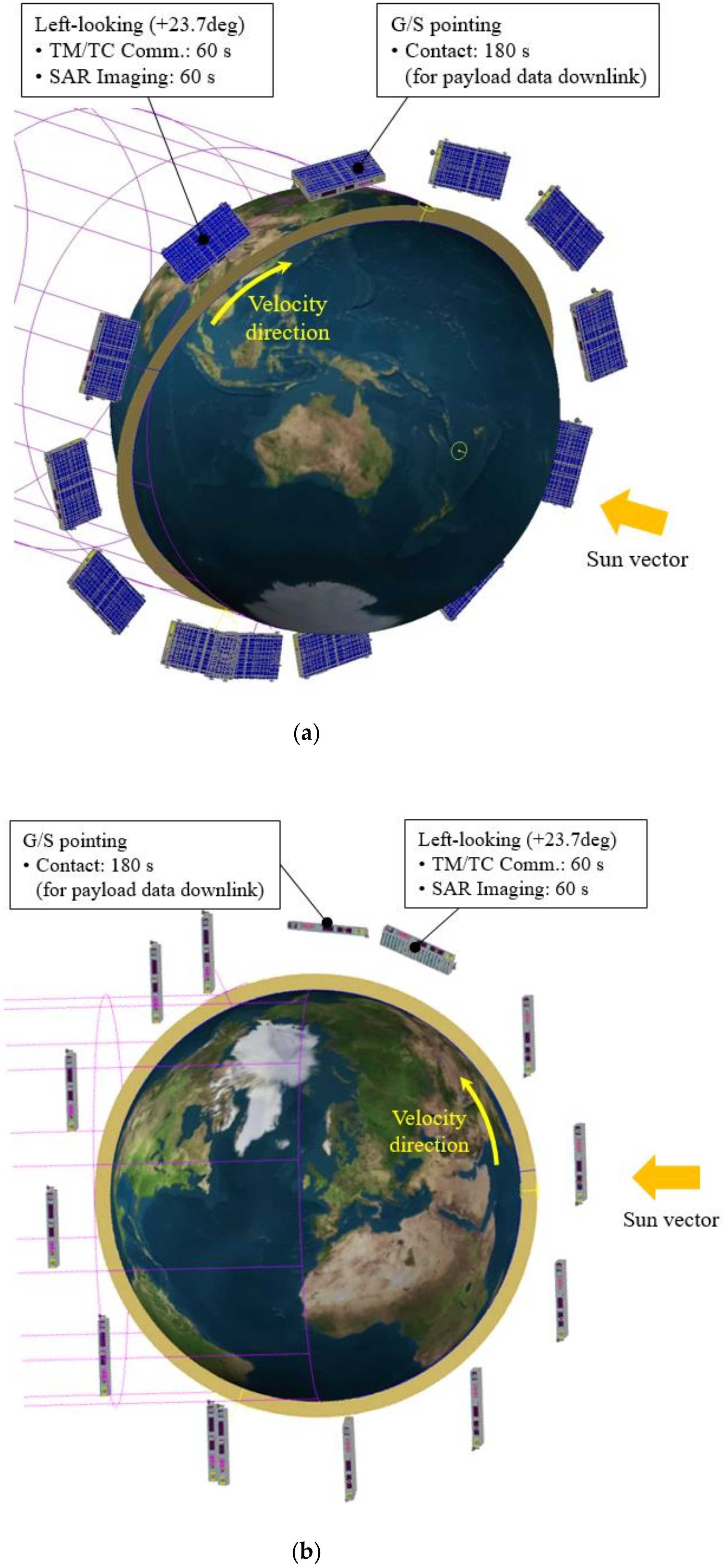
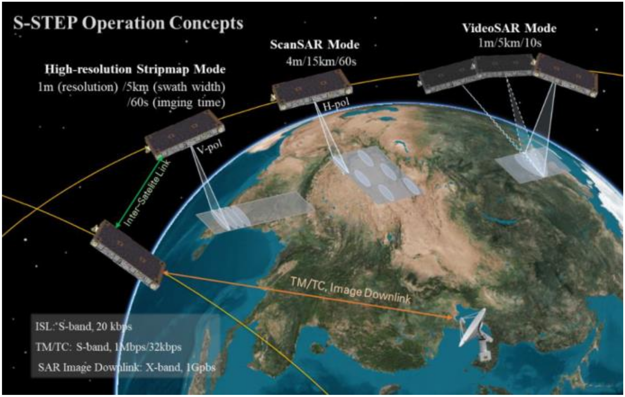
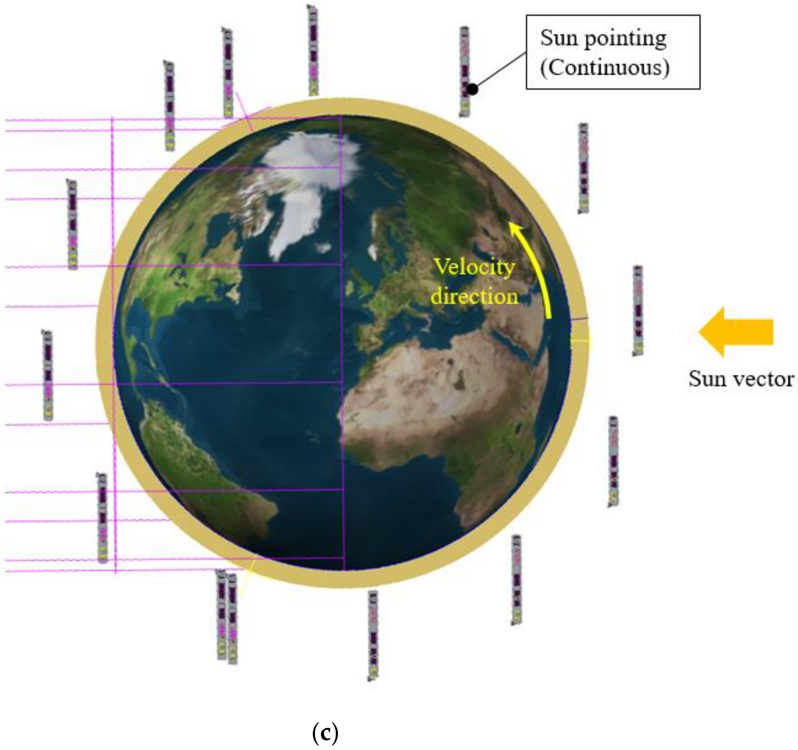
The S-STEP program has been started to develop an 80 kg class lightweight small SAR satellite for high-resolution SAR imagery for environmental investigation, surface mapping, and disaster monitoring. The mission operation concept of the S-STEP system is shown in Figure 1 [22]. The S-STEP system is operated at LEO and provides a 1 m resolution stripmap image, 4 m resolution ScanSAR image, and 1 m resolution VideoSAR for 10 s duration to capture the earth’s targets of interest. The SAR payload of S-STEP is an aperture-coupled cavity-backed microstrip patch array antenna, which can achieve high radio frequency (RF) gain. A total of 192 TRMs were applied to implement electronic beam steering capability in the elevation direction of the antenna. The SAR image data are transferred to an integrated avionics unit (IAU) for storage. The stored data are transmitted to the ground station through a 1 Gbps X-band downlink module. The expected mission lifetime of the S-STEP system is 3 years. The S-STEP program ultimately aims to implement a satellite constellation for near real-time SAR observation. Therefore, the S-band inter-satellite link (ISL) system is considered for immediate communication link between the satellites. Table 1 lists the basic system specifications of S-STEP [22].
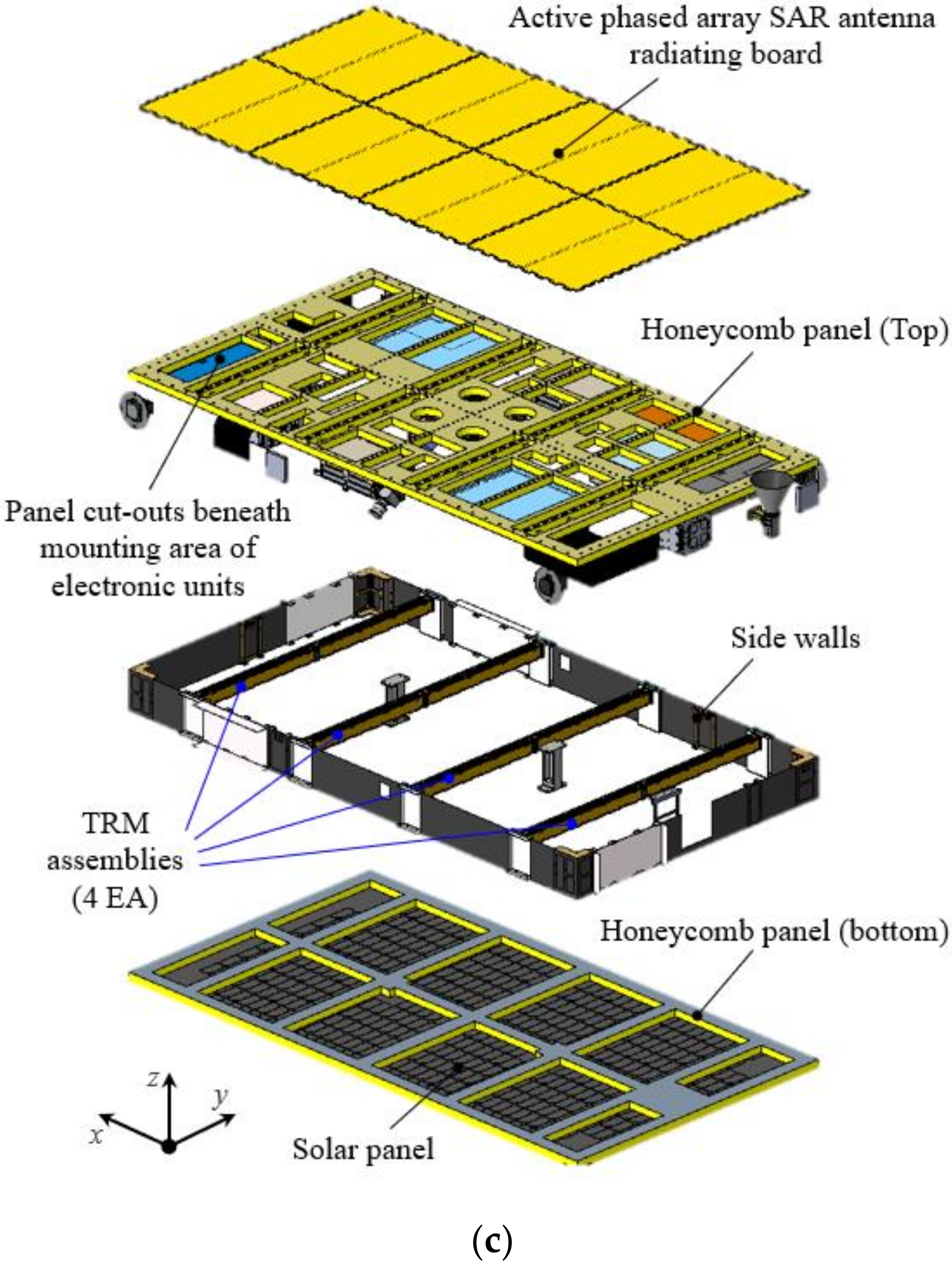
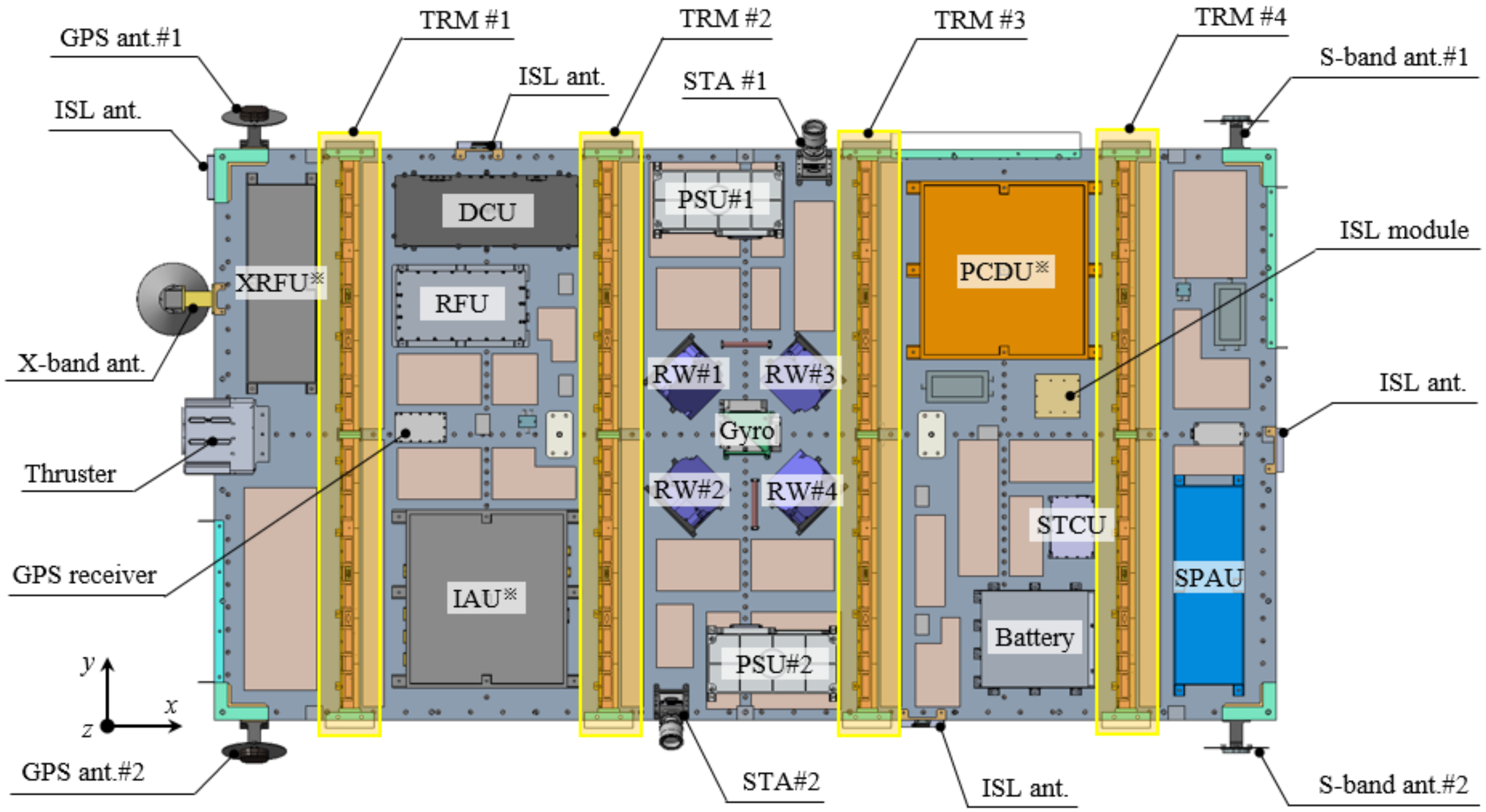
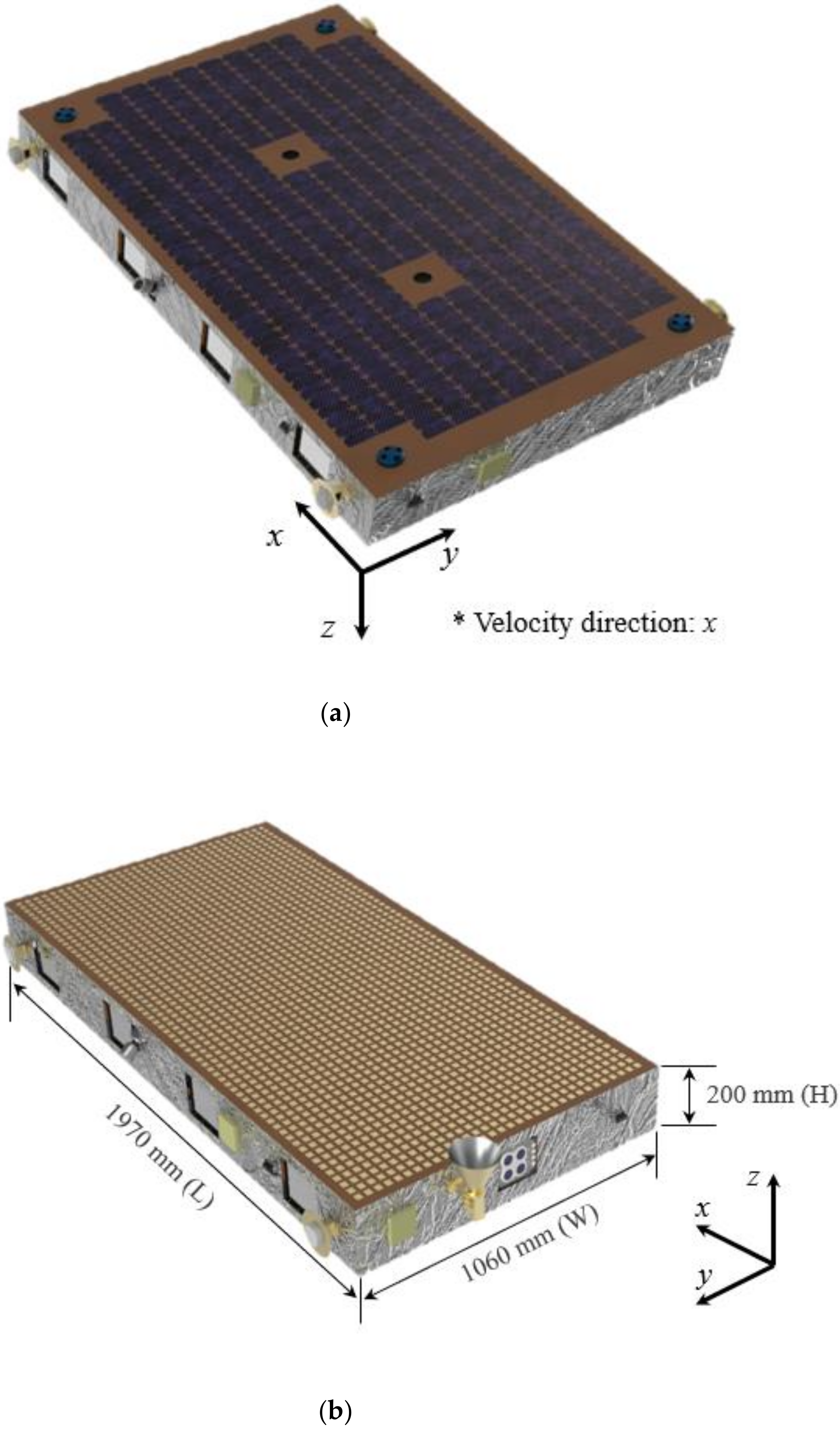
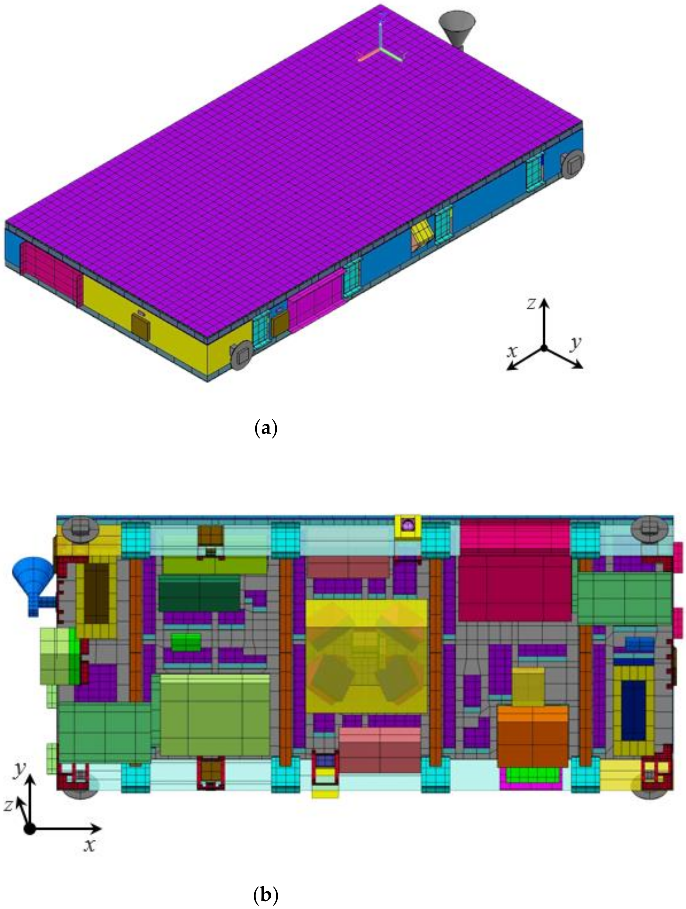
Figure 2 shows the mechanical configurations of the S-STEP satellite. The primary feature of its mechanical design is the bus–payload integrated flat panel-shaped satellite structure. This mechanical configuration is advantageous to ensuring the dimensional stability of the satellite, especially the SAR antenna, in extreme on-orbit thermal environments. One more essential feature of this satellite configuration is the additional 0 g compensation device for on-ground testing of SAR antennas, as it is a nondeployable-type antenna. All payload and bus electronic units are mounted on the top aluminum-skin honeycomb composite panel as the configuration shows in Figure 2c and Figure 3. Four reaction wheels (RWs) in a pyramidal configuration with an optimal tilt angle are mounted at the center of the satellite to minimize the moment of inertia and their power consumption. The X-band antenna for payload data downlink and two S-band antennas for telecommand/telemetry (TM/TC) communication are installed on the side walls in −x, +y, and −y sides of the satellite. The GPS and ISL antennas are also installed on various locations of the side walls. To operate the satellite, 340 W of electrical power is produced at beginning of life (BoL) and stores the power in the battery with 648 Wh capacity. Among the on-board instruments of satellite, the four TRM assemblies require the largest amount of power consumption. In the SAR imaging operation, the stored battery power is mainly used to operate these TRM assemblies.
The satellite is integrated on a VFOD introduced in a previous study [22], which has the dual functions of the orbital insertion of satellite and the entire spacecraft vibration isolation. The main function of VFOD is an on-orbit satellite separation combined with a side-mounting ride-share platform. The additional function of launch vibration isolation was a key factor in minimizing the satellite mass, as the structural reinforcement was reduced by launch load mitigation. The multifunctional structure of payload components, the adoption of a new structural design methodology called Oh-Park methodology [23] for spaceborne electronics, and the proposed thermal design strategy contributed to further satellite mass reduction. The mass of the satellite was 80.3 kg due to these mechanical design strategies. A previous study [22] showed that the SAR performance index with respect to the satellite mass was close to those of the other small SAR satellites developed in accordance with the NewSpace paradigm. This study verified the feasibility of the proposed mechanical design strategies for S-STEP through satellite system-level structural analysis.

3. New Thermal Design Strategy for S-STEP

The primary objective of establishing a new thermal design for S-STEP is to ensure long-term high-resolution SAR imaging duration for 60 s regardless of the right- and left-looking modes of an SAR antenna. In addition, the thermal design shall maintain all onboard components within their allowable temperature limits (Table 2) in extreme on-orbit thermal environments with minimal use of heater power. To accomplish the thermal design objectives, the heat of the high-power components, such as the TRM assemblies, power conditioning and distribution unit (PCDU), IAU, and battery, shall be effectively dissipated to the outer space. These are the main focuses of the proposed thermal design. To implement a “lighter” satellite, the thermal design is mainly based on passive thermal control approaches using surface coatings, MLI, and heat dissipation radiators. The use of thermal hardware that occupy some portion of the mass to some extent, such as heat pipe and doubler used conventionally [13], are avoided for S-STEP.
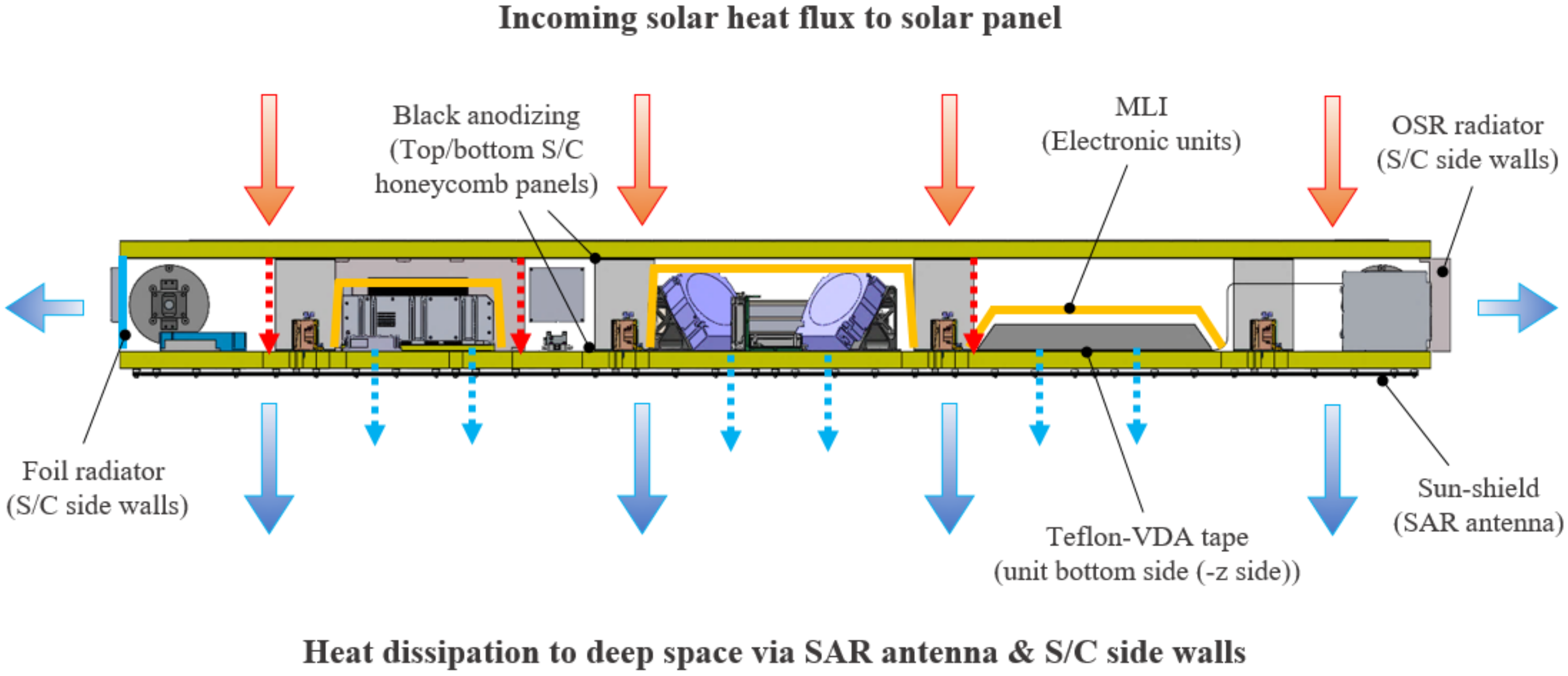
Figure 4 shows the new thermal design concept for the proposed S-STEP system. The front SAR antenna surface (−z side) and side walls (x and y sides) are exposed to relatively lower environmental fluxes. Therefore, these surfaces can be used for dissipating satellite internal heat to outer space. Moreover, the incoming solar heat flux on the solar panel (+z side) can be used as a heat source to compensate for heat loss. The optimization of solar heat flux and heat dissipation of the satellite is achieved by applying various thermal coatings, MLIs, and radiators to control the heat exchange between structural elements and components, which results in minimizing the heater power budget, contributing to further satellite mass reduction due to decreases in solar panel and battery sizes. This thermal design concept is the most innovative and unique aspect of the proposed thermal design strategy for S-STEP that has never been attempted in the previous small SAR satellite programs.
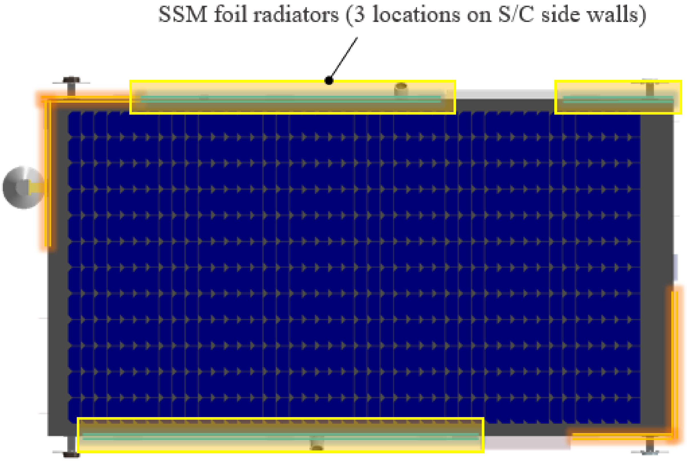
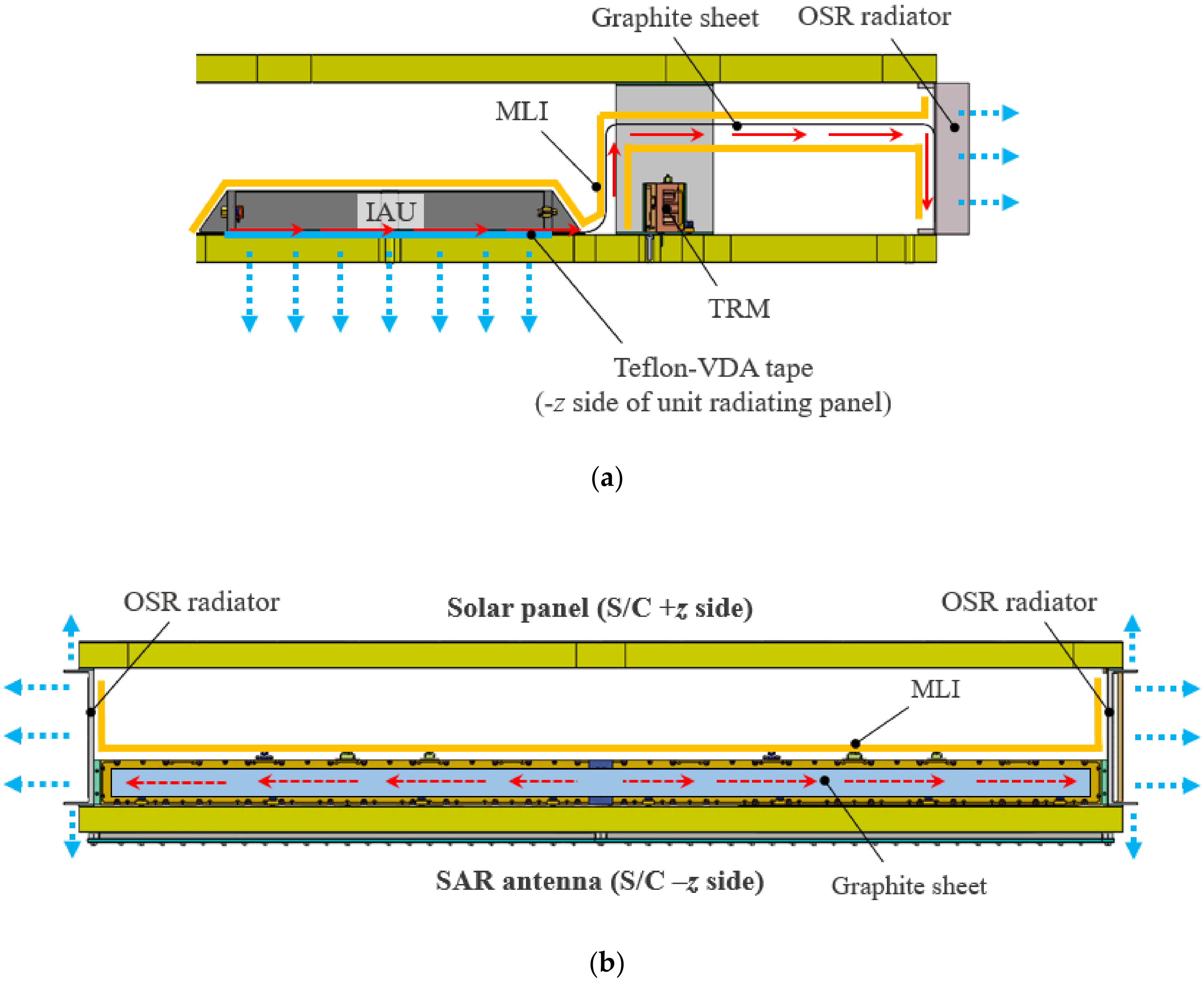
In the thermal design, an RF-transparent sunshield covers the external side of the SAR antenna for heat rejection. The primary satellite structures of aluminum-skin honeycomb panels are black anodized for minimizing the thermal gradient over the entire satellite structure by facilitating the internal heat exchange. The internal waste heats of payload and bus electronic units and solar panels are dissipated via mounting surfaces (−z side) to the SAR antenna. Thus, most honeycomb panel areas, including the mounting areas for electronic units, were cut-out for their effective heat dissipation (Figure 2c). These cut-outs were advantageous to reduce the satellite mass as well. The electronic unit mounting surfaces (+z side) were coated with Teflon-VDA tape with high emissivity. The rest of their surfaces were covered with MLI to avoid the absorption of heat radiated from the solar panel. For further heat dissipation, second surface mirror (SSM) foil radiators were integrated on the sidewalls (Figure 5).
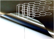
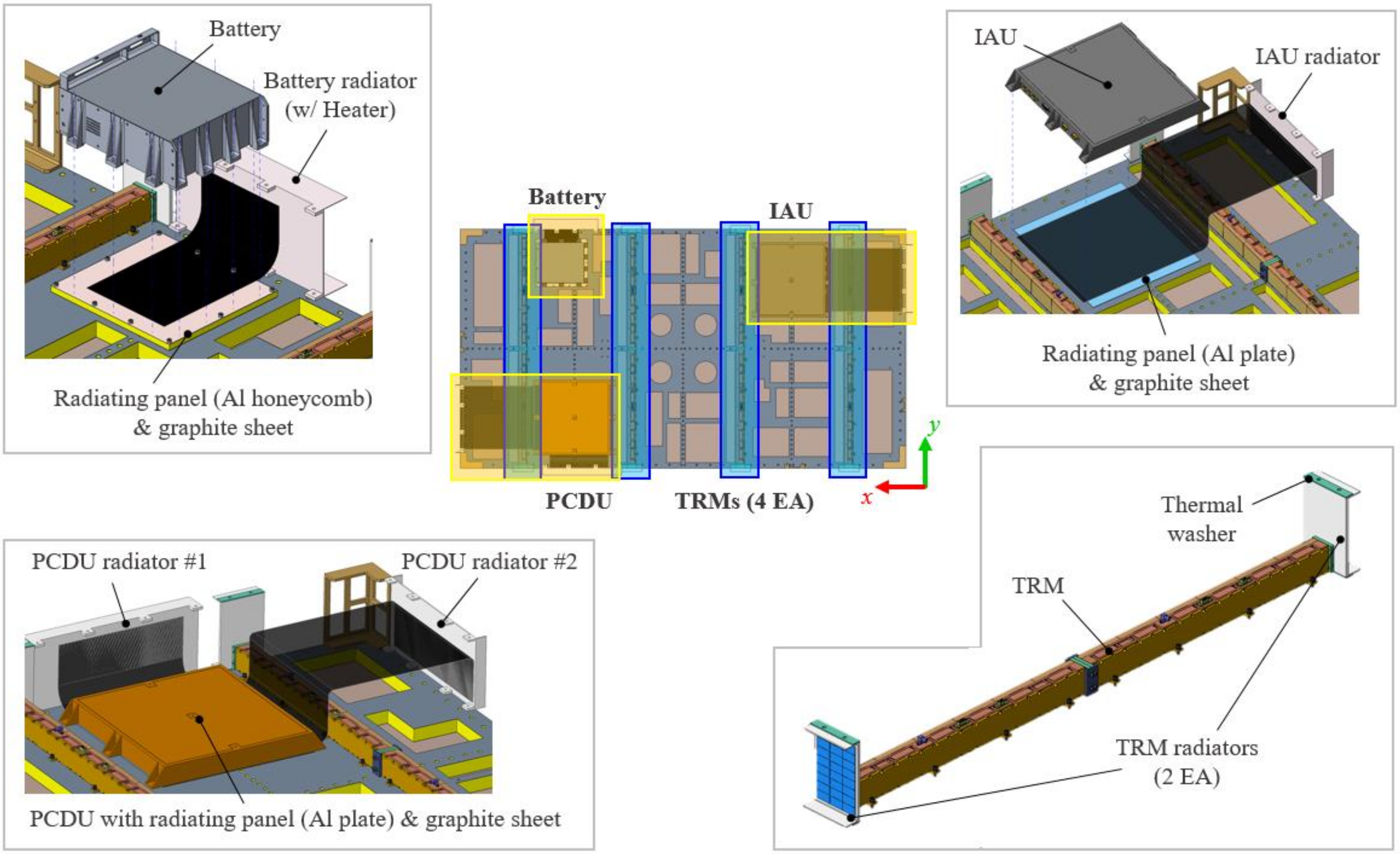
For effective heat dissipation of PCDU, IAU, and battery producing relatively larger amount of waste heat than the others, this study focused on the unique characteristics of a lightweight flexible graphite sheet. The graphite sheet is a popular thermal interface material and has been used in various fields, such as portable devices, electronics, and space engineering [24]. It has many advantages, such as high thermal conductivity in the in-plane direction of the sheet (four times higher than copper), light weight, flexibility to bending, high heat-resistance, and availability to use in a vacuum. All these characteristics make the graphite sheet attractive to use for thermal control of small satellites with a limited mass budget. Table 3 lists the specifications of the graphite sheet used for the S-STEP satellite. In the S-STEP thermal design, the graphite sheet was used to form the heat transfer paths from the IAU, PCDU, and battery to the dedicated radiators, respectively (Figure 6 and Figure 7a). Both ends of the graphite sheet were clamped on the unit and radiator, respectively, to implement a secure thermal contact. For PCDU, where a larger amount of heat rejection is required than others, two radiator assemblies with graphite sheets were applied to the unit. The thermal control solution using a graphite sheet could be more advantageous than the conventional heat pipe in terms of light weight and unnecessity to maintain the orientation to the horizontal plane of the pipe to avoid the gravitational effect during an on-ground test. A total of 15 graphite sheet layers, determined on the basis of a previous study [25], were applied with respect to each component.
In the thermal design, the battery module is the only component requiring heater control for temperature management to maintain the electrical power storage capacity. This fact indicates that the power budget-saving can be expected based on the proposed thermal design strategy. A Kapton polyimide film heater was attached adjacent to the battery radiator. Through the preliminary thermal analysis, the on/off set-points of the heater are set as 15/16 °C, and the heater power was determined as 30 W to satisfy the requirement of heater duty to be lower than 80%.
The effective heat dissipation of TRM is a crucial factor in achieving the long-term SAR imaging duration of 60 s in both left- and right-looking modes of SAR antenna in orbit. In the previous study [22], the concept of the multifunctional TRM assembly structure was introduced as the configuration shown in Figure 6. A single TRM assembly was integrated with two optical solar reflector (OSR) radiators at both ends to effectively dissipate the heat produced during SAR imaging operation (Figure 7b). In this study, the U-shaped configuration of each radiator further enhanced the heat dissipation capability by increasing the radiating area. In addition, the proposed design was intended to dissipate heat to the bent parts of the radiator, even if the incidence angle of heat flux varied with the attitude maneuvering of the satellite. The radiator design also provided mechanical interfaces to integrate the top and bottom honeycomb panels of the satellite. To minimize the thermal gradient over the TRM assembly, a graphite sheet was integrated along its sidereal surface. The TRM assembly was radiatively and conductively decoupled from the satellite using MLI and thermal washers to secure heat dissipation capability.

4. On-Orbit Thermal Analysis of S-STEP

4.1. Overview of Thermal Analysis

To verify the effectiveness of the proposed thermal design strategy in meeting the design objectives of the S-STEP system described in Section 3, a system-level transient on-orbit thermal analysis was performed. Table 4 lists the orbital conditions used for the thermal analysis. The hot and cold conditions are defined in the table to implement critical thermal environments on the satellite. The hot and cold cases corresponded to when the satellite was exposed to the highest and lowest environmental heat fluxes, respectively. The thermal analysis cases are defined in Table 5. Cases 1 and 2, respectively, correspond to the SAR imaging operation in the left-and right-looking modes for the hot environment. Cases 3 and 4, respectively, correspond to the SAR imaging operation in the left-and right-looking modes for the cold environment. Case 5 corresponds to the safe-hold mode for the cold environment.
Figure 8a,b, respectively, show the external and internal configurations of a thermal mathematical model (TMM) of the S-STEP system for on-orbit thermal analysis. A total of 13,718 nodes were used for modeling the TMM. The TMM was constructed using Thermal Desktop [26], a CAD-based geometric interface of the commercial on-orbit thermal analysis tool of Systems Improved Numerical Differencing Analyzer/Fluid Integrator (SINDA/FLUINT) [27]. A RadCAD was used to calculate the radiation exchange factors and orbital heating rates based on the geometrical mathematical model (GMM) created by Thermal Desktop. The GMM and output data of RadCAD were used as inputs for on-orbit thermal analysis using SINDA/FLUINT. The representative orbital profiles of S-STEP created based on the information specified in Table 4 are shown in Figure 9a–c. In the SAR imaging operation, the satellite sequentially performed TM/TC communication (60 s), SAR imaging (60 s), and ground station (G/S) pointing for image data downlink (180 s). In the safe-hold mode, the satellite maintained the Sun-pointing of the solar panel (Figure 9c). Table 6 and Table 7, respectively, list the thermo-physical and -optical properties used for the thermal analysis. The thermal network was implemented using a node-to-node conductor or a surface-to-surface contactor in the thermal desktop.

4.2. Results of Thermal Analysis

Figure 10 shows the representative thermal analysis results for Case 1—the orbital temperature profiles of components newly developed in this program when the left-looking SAR imaging operation was executed in the hot environment. This is the worst hot condition for the S-STEP system among the analysis cases listed in Table 5. Temporal temperature variations occurred due to the changes in incidence angle of satellite with respect to the sun and earth in accordance with the orbital revolution of satellite, as shown in Figure 9. The thermal design to dissipate the heat of electronic units through SAR antenna controlled their temperatures well, especially high-power electronic units, such as PCDU, IAU, and battery, combined with sidewall radiators and thermal paths implemented by the graphite sheet. The key payload components of TRM assemblies were operated under a moderate temperature condition, ranging from 29.6 to 42.2 °C, despite their total heat dissipation of 1460 W (365 W per a single TRM assembly) during SAR imaging operation. Figure 11a,b, respectively, show the predicted maximum and minimum temperatures of all onboard components in Case 1 (left-looking) and Case 2 (right-looking) when the SAR imaging operation is executed in the hot environment. The graph also shows the operating and survival temperature limits of each component. In both cases, the temperatures of all components were maintained within their allowable limits for the operating conditions specified in Table 2. In particular, the high-power components of IAU and PCDU were operated with sufficient temperature margins of more than 6.7 °C by effective heat dissipation via the SAR antenna and sidewall radiators. The battery temperature was maintained above 25.3 °C, and the heater was not operated during the entire orbit. These analysis results indicated that the proposed thermal design strategies were effective for stable satellite operation and achieving the required SAR imaging duration of 60 s, regardless of SAR left- and right-looking modes, even in the worst hot environment.
Figure 12 shows Case 3 analysis results—the orbital temperature profiles of representative onboard components when left-looking SAR imaging operation is executed in the cold environment. The predicted maximum and minimum temperatures of the entire onboard components in Case 3 (left-looking) and Case 4 (right-looking) when the SAR imaging operation was executed in the cold environment are shown in Figure 13a,b, respectively. These figures show that all components were within the temperature ranges of operating conditions. The temperatures of TRMs were moderately maintained within the range of −5.6 to 0 °C in both the left- and right-looking modes of SAR antenna. The battery temperature was maintained above 14 °C by heater control, and the duty was 36%. Figure 14 shows the thermal analysis results in Case 5 (safe-hold mode, cold environment). All non-operating components kept the temperature within the survival limits. The heater duty was 39% in this case. These on-orbit thermal analysis results showed that the proposed S-STEP system would be stably operated throughout the mission duration under the expected on-orbit thermal environment.
The TRM exhibits temperature-dependent RF output characteristics, such as gain and phase errors, which negatively affect in-antenna beam formation [28]. Although the S-STEP SAR payload has an output error compensation function, an additional technique to contribute to the error compensation, in the thermal control perspective, might be to reduce the spatial temperature difference (ΔTs) over the TRM assemblies. Figure 15 shows the analyzed temperature contour of four TRM assemblies at the time when the maximum ΔTs occurred during the left-looking SAR imaging in the hot case. Table 8 summarizes ΔTs of each TRM in the left- and right-looking modes in the hot and cold environments (Cases 1–4). The ΔTs values of TRMs did not increase more than 7.6 °C in all cases.
In this study, we also analyzed ΔTs over the SAR radiating board and satellite primary structure because they are important in assuring the image quality of SAR antenna against the dimensional instability due to thermal distortion. Figure 16a,b, respectively, show the representative temperature contours of SAR radiating board and satellite platform structure in the left-looking SAR imaging operation in the hot environment in which the ΔTs values are 56.6 and 13.5 °C. The antenna root–mean–square (RMS) surface error and antenna best-fit plane (ABFP) angle estimated in the previous study [22], based on those thermal analysis results, were 0.7 mmrms and 0.005°, respectively. These values were sufficiently low to comply with the S-STEP SAR antenna requirements (RMS error of <1.55 mmrms and ABFP angle of <0.02°).

5. Experimental Verification of Key Thermal Design

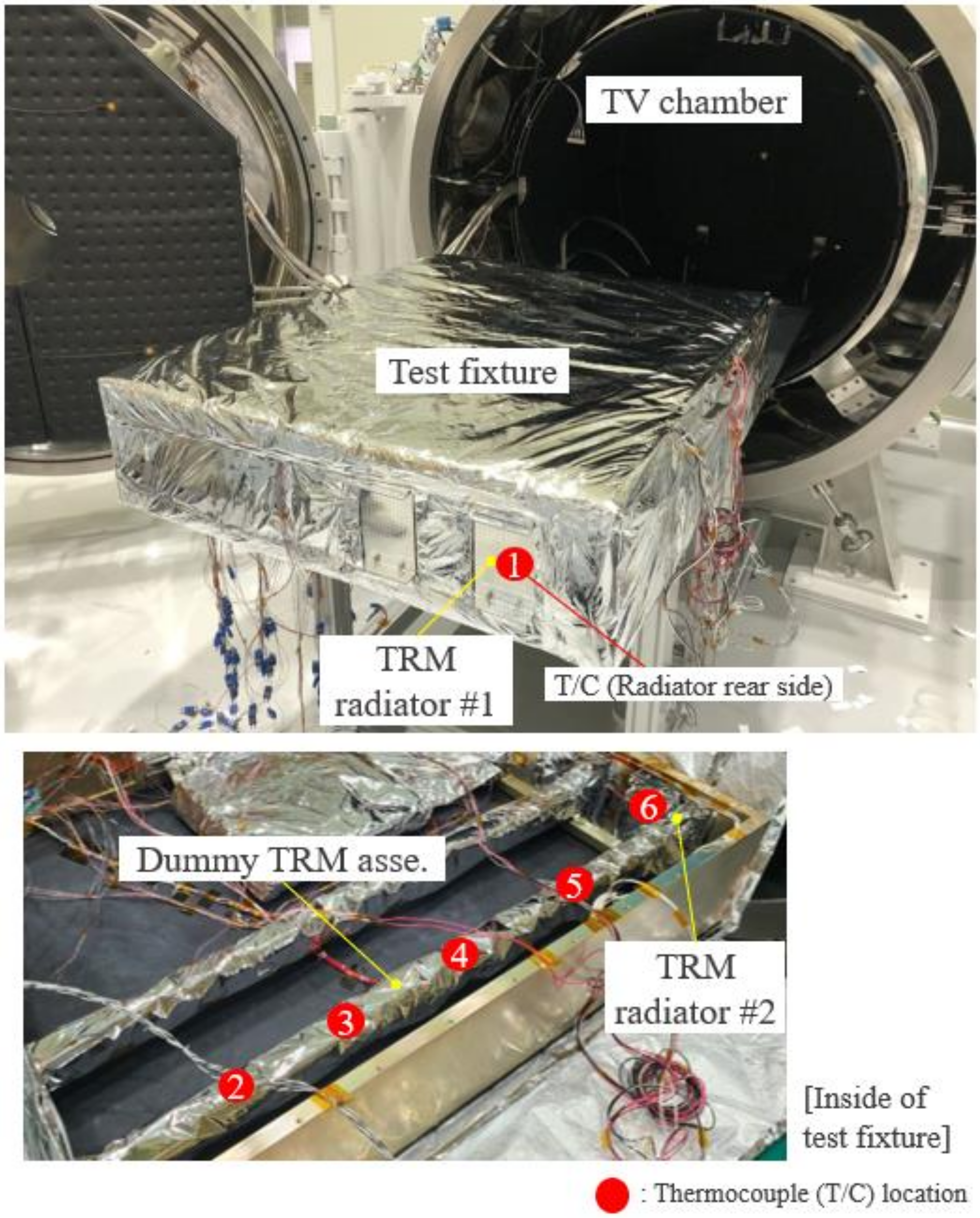
To confirm the design effectiveness of TRM radiators, a space-simulated thermal vacuum (TV) test was performed using a dummy model of TRM assembly with radiators. Figure 17 shows the configuration of the TV test set-up. The test specimen comprises a dummy TRM assembly integrated inside the text fixture. The test specimen, except for the front side of radiators, was entirely covered with MLI, and it was conductively isolated from the chamber base plate to avoid an unnecessary heat outflow from the TRM. The heat dissipation of TRM was simulated by a test heater group with 160 W power capacity attached to various locations of the dummy TRM. The heater was also applied on the rear side of each radiator to simulate the incoming environmental heat flux. In the test, the graphite sheet was not applied to the TRM structure because the test objective was to primarily verify the heat dissipation performance of the integrated radiators.
The specimen was exposed to the thermal environment of −70 °C controlled by a chamber shroud. The operating temperature of the radiators was maintained to 20 °C by the heater control to simulate on-orbit temperature conditions. The temperature reference point was located near the center of TRM to declare thermal stabilization, as when the temperature variation is less than 2 °C/h. The TV test was performed under a pressure level of 10−5 torr. In the test, the ΔTs between the center of the TRM and radiator was the main factor to judge the effectiveness of the proposed thermal design.
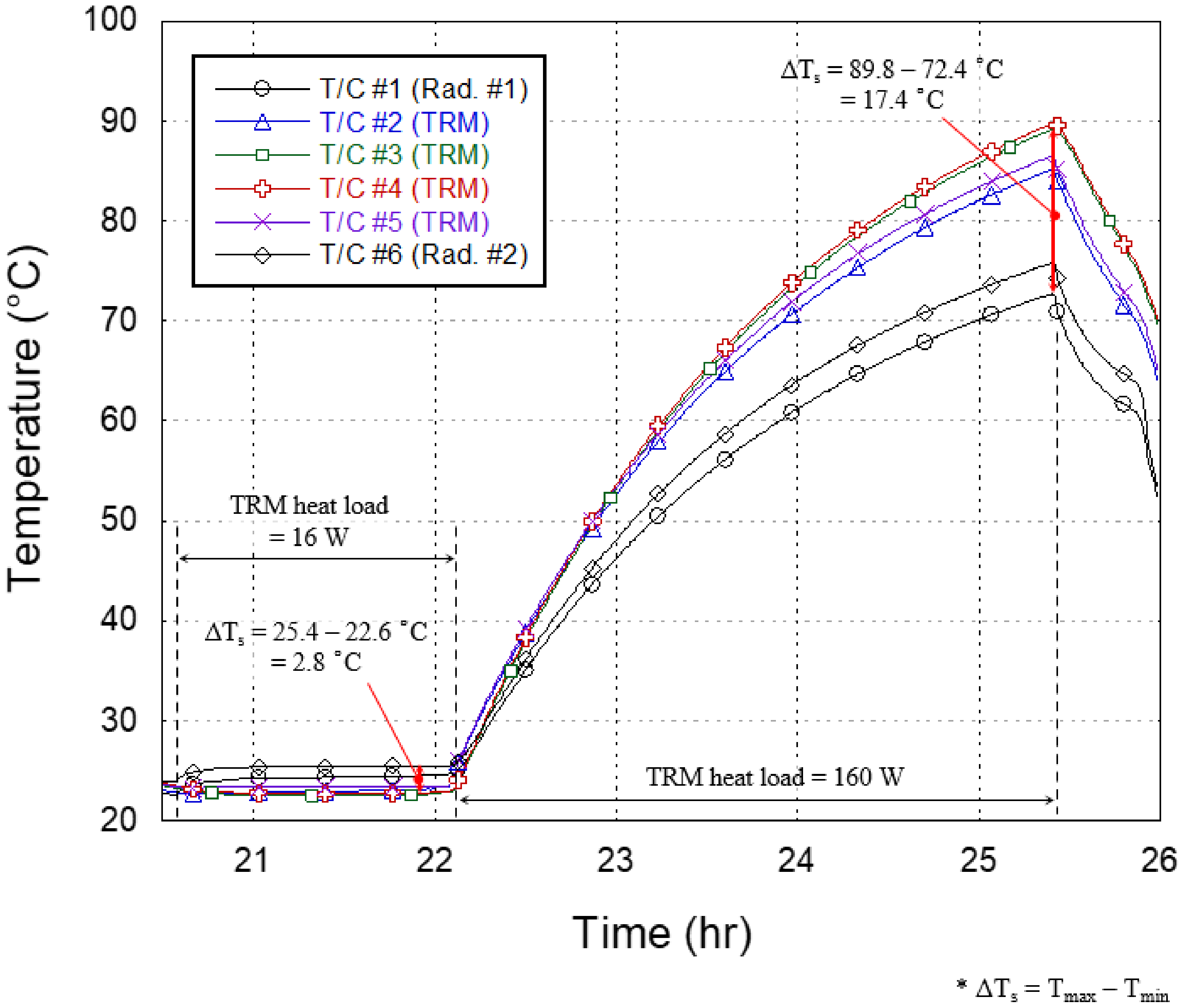
Figure 18 shows the temperature profile obtained by thermocouples when the specimen was thermally stabilized. In the thermal analysis, the orbital average heat dissipation of TRM assembly was approximately 4 W because it was operated for only 60 s during SAR imaging, although its power dissipation was 365 W. In the test, the constant heat load of 16 W was first applied to the TRM, which was a sufficiently high amount of heat load to simulate the orbital average heat dissipation. The TRM reached 25.4 °C, and the maximum ΔT
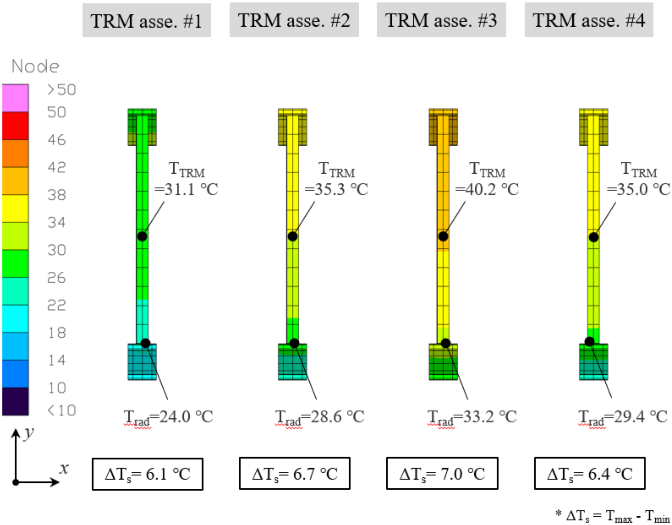
s between the TRM and radiator was 2.8 °C. Meanwhile, the thermal analysis results shown in Figure 15 indicated that the maximum ΔTs value of TRM assemblies #1–#4 was 7.0 °C when the radiator temperatures were ranging from 24.0 to 29.4 °C. Table 8 also shows that ΔTs was less than 7.6 °C in all cases of SAR imaging operations. The thermal conductance value between the TRM and radiator, simply estimated from the heat load and ΔTs observed from the test, was 5.7 W/K. Subsequently, the heat load of 160 W was applied to the TRM to observe further heat dissipation capability. The increase in TRM temperature was only less than 1 °C after 60 s, and the temperature was stabilized at 89.8 °C. The ΔTs at the stabilized temperature was 17.4 °C. The thermal conductance value between the TRM and radiator in this condition increased to 9.2 W/K as the radiated heat energy increases at higher radiator temperature. These test results indicated that the proposed radiator design had sufficient heat dissipation capability for thermal control of TRM assembly in on-orbit SAR imaging operation conditions.

6. Conclusions

In the present study, a new thermal design strategy was proposed for an 80 kg class lightweight active X-band small SAR satellite, S-STEP, for high-resolution earth observation. Considering the bus–payload integrated flat panel-type unique satellite configuration, the proposed thermal design of S-STEP mainly relied on the optimization of environmental heat flux on the satellite by passive thermal control approaches. A lightweight flexible graphite sheet with high thermal conductivity was used for heat dissipation of some high-power components via radiators. A thermal design of the key payload component of TRM assembly with dedicated radiators was proposed. To validate the effectiveness of the proposed thermal design, an on-orbit thermal analysis of S-STEP was performed in various cases of SAR-looking modes. The analysis results showed that the proposed thermal design ensured the required SAR imaging duration of 60 s regardless of left- and right-looking modes of SAR antenna while keeping all onboard components within the allowable temperature range. The spatial temperature differences in the TRM assembly and satellite primary structure of honeycomb panels were also evaluated through the analysis. The results verified that the proposed thermal design contributed to ensuring the thermal stability of the SAR payload. In the future, the effectiveness of thermal design using graphite sheets for high-power components will be experimentally verified through the TV test. In addition, the entire thermal design of S-STEP will be verified through structural–thermal model tests. The new thermal design strategy proposed in this study would be useful and applicable to the flat panel-type small satellite for SAR observation, communication, and internet service missions.

Author Contributions

Conceptualization, H.-U.O.; methodology, H.-U.O. and B.-G.C.; validation, B.-G.C., K.-R.K.; formal analysis, B.-G.C.; investigation, B.-G.C., K.-R.K., H.-U.O.; resources, S.-C.S., H.-U.O.; data curation, B.-G.C., T.-Y.P.; writing—original draft preparation, T.-Y.P.; writing—review and editing, T.-Y.P.; visualization, T.-Y.P., B.-G.C.; supervision, H.K., S.-C.S., H.-U.O.; project administration, H.-U.O.; funding acquisition, H.K., H.-U.O. All authors have read and agreed to the published version of the manuscript.

Funding

This research was funded by the Agency for Defense Development (ADD).

Institutional Review Board Statement

Not applicable.

Informed Consent Statement

Not applicable.

Data Availability Statement

The data used to support the findings of this study are available from the corresponding author upon request.

Acknowledgments

This research was supported by the Agency for Defense Development (ADD).

Conflicts of Interest

The authors declare that they have no conflict of interest.

References

  1. Morgan Stanley. The Space Economy’s Next Giant Leap. 2021. Available online: https://www.morganstanley.com/Themes/global-space-economy (accessed on 1 September 2021).
  2. Kak, A.; Akyildiz, I.F. Large-Scale Constellation Design for the Internet of Space Things/CubeSats. In Proceedings of the 2019 IEEE Globecom Workshops (GC Wkshps), Waikoloa, HI, USA, 9–13 December 2019. [Google Scholar]
  3. Planet Labs Inc. Planet. Available online: https://www.planet.com/ (accessed on 1 September 2021).
  4. Starlink. Available online: https://www.starlink.com/ (accessed on 1 September 2021).
  5. Project Kuiper. Available online: https://www.amazon.jobs/en/teams/projectkuiper (accessed on 1 September 2021).
  6. Li, J. Satellite Remote Sensing Technologies; Springer Nature: Cham, Switzerland, 2021. [Google Scholar]
  7. Paek, S.W.; Balasubramanian, S.; Kim, S.; de Weck, O. Small-satellite synthetic aperture radar for continuous global biospheric monitoring: A review. Remote Sens. 2020, 12, 2546. [Google Scholar] [CrossRef]
  8. Ignatenko, V. ICEYE Microsatellite SAR Constellation Status Update: Evaluation of first commercial imaging modes. In Proceedings of the IEEE International Geoscience and Remote Sensing Symposium (IGARSS), Waikoloa, HI, USA, 26 September–2 October 2020. [Google Scholar]
  9. Capella Space. Available online: https://www.capellaspace.com/capella-unveils-worlds-highest-resolution-commercial-sar-imagery/ (accessed on 1 September 2021).
  10. Synspective. Available online: https://synspective.com/satellite/satellite-strix/ (accessed on 1 September 2021).
  11. i-QPS. Available online: https://i-qps.net/ (accessed on 1 September 2017).
  12. Saito, H.; Akbar, P.; Tanaka, K.; Ijichi, K.; Mita, M.; Pyne, B.; Kaneko, T.; Obata, T. Engineering-Model Results of X-band Synthetic Aperture Radar for Small Satellite and Its Application to Constellation Mission. In Proceedings of the 32nd Annual Small Satellite Conference, Logan, UT, USA, 4–9 August 2018; SSC18-VII-01. pp. 1–9. [Google Scholar]
  13. Perellón, M.; Alvarez, R.; Petrini, P.; Sauer, A.; Dolce, S. Sentinel 1–spacecraft and SAR antenna thermal design, analysis, verification and flight performances. In Proceedings of the 45th International Conference on Environmental Systems (ICES), Bellevue, WA, USA, 12 July 2015. [Google Scholar]
  14. Cohen, M. NovaSAR-S low cost spaceborne SAR payload design, development and deployment of a new benchmark in spaceborne radar. In Proceedings of the IEEE Radar Conference (RadarConf), Seattle, WA, USA, 8–12 May 2017. [Google Scholar]
  15. Tan, C.; Yu, Z.; Sun, H.; Shi, G.; Liu, X.; Zhou, Y.; Li, G. Integrated design of X-band phased array antenna with LTCC 3D T/R module. IEICE Electron. Express 2020, 17, 1–6. [Google Scholar] [CrossRef]
  16. Yang, L.; Li, Q.; Kong, L.; Gu, S.; Zhang, L. Quasi-all-passive thermal control system design and on-orbit validation of Luojia 1-01 satellite. Sensors 2019, 19, 827. [Google Scholar] [CrossRef] [PubMed] [Green Version]
  17. Yendler, B.; Meginnis, A.; Reif, A. Thermal Management for High Power Cubesats. In Proceedings of the 34th Annual Small Satellite Conference, Logan, UT, USA, 28 July 2020; pp. 1–19. [Google Scholar]
  18. Ueno, A.; Yamada, K.; Miyata, K.; Nagano, H. Proposal of Functional Thermal Control Systems for High-Power Micro-Satellite and Its Demonstration under Thermal Vacuum Condition. J. Electron. Cool. Therm. Control 2018, 8, 1–17. [Google Scholar] [CrossRef] [Green Version]
  19. Manente, M.; Trezzolani, F.; Magarotto, M.; Fantino, E.; Selmo, A.; Bellomo, N.; Pavarin, D. REGULUS: A propulsion platform to boost small satellite missions. Acta Astronaut. 2019, 157, 241–249. [Google Scholar] [CrossRef]
  20. AlShehhi, A.; AlMarar, A.; AlShehhi, Y.; AlAmeri, M. Thermal design evaluation of Loop Heat Pipe for small satellite applications using graphene Nano-Particles. In Proceedings of the 70th International Astronautical Congress (IAC), Washington, DC, USA, 21–25 October 2019. [Google Scholar]
  21. Sharath, B.K.; Joteppa, S.; Dibbi, S.; Chippalkatti, V.; Rajendran, P.; Uma Ravindra, M. Thermal Investigation of Power Supply Module (QDR-PSM) for Space Application Using Numerical and Experimental Approach. In Advances in Small Satellite Technologies; Springer: Singapore, 2020; pp. 493–508. [Google Scholar]
  22. Kwon, S.C.; Son, J.H.; Song, S.C.; Park, J.H.; Koo, K.R.; Oh, H.U. Innovative Mechanical Design Strategy for Actualizing 80 kg-Class X-Band Active SAR Small Satellite of S-STEP. Aerospace 2021, 8, 149. [Google Scholar] [CrossRef]
  23. Park, T.Y.; Oh, H.U. New PCB strain-based structural design methodology for reliable and rapid evaluation of spaceborne electronics under random vibration. Int. J. Fatigue 2021, 146, 106147. [Google Scholar] [CrossRef]
  24. Kaneka Corporation. High Thermal Conductive Graphite Sheet, GraphinityTM 2021. Available online: http://www.elecdiv.kaneka.co.jp/english/graphite/index.html (accessed on 1 September 2021).
  25. Park, D.; Miyata, K.; Nagano, H. Thermal design and validation of radiation detector for the ChubuSat-2 micro-satellite with high-thermal-conductive graphite sheets. Acta Astronaut. 2017, 136, 387–394. [Google Scholar] [CrossRef]
  26. C&R Technologies. Thermal Desktop User’s Manual–A Cad Based System for Thermal Analysis and Design; Version 6.1; C&R Technologies: Boulder, CO, USA, 2019. [Google Scholar]
  27. C&R Technologies. SINDA/FLUINT User’s Manual–General Purpose Thermal/Fluid Network Analyzer; Version 6.1; C&R Technologies: Boulder, CO, USA, 2019. [Google Scholar]
  28. Adolph, M.; Hackenberg, U.; Reber, R.; Rieger, R.; Schweizer, B.; Adelseck, B.; Brugger, H.; Lorcher, M. High-precision temperature drift compensated T/R-module for satellite based SAR applications. In Proceedings of the IEEE European Microwave Conference, Paris, France, 4–6 October 2005. [Google Scholar]
Figure 1. Mission operation concept for S-STEP system [22].
Aerospace 08 00278 g001
Figure 2. Mechanical configurations of S-STEP satellite: (a) view from S/C −z side, (b) view from S/C +z side, and (c) exploded view.
Aerospace 08 00278 g002aAerospace 08 00278 g002b
Figure 3. Internal configuration of S-STEP satellite (DCU: digital control unit; RFU: radio frequency unit; PSU: power supply unit; TRM: transmit/receive module; STA: star tracker assembly; RW: reaction wheel; ISL: inter-satellite link; IAU: integrated avionics unit; SPAU: S-band power amplifier unit; XRFU: X-band RF unit; PCDU: power conditioning and distribution unit; GPS: global positioning system; STCU: star tracker control unit).
Aerospace 08 00278 g003
Figure 4. The proposed thermal design concept for S-STEP satellite.
Aerospace 08 00278 g004
Figure 5. Allocation of SSM foil radiators on S-STEP satellite.
Aerospace 08 00278 g005
Figure 6. Thermal design concept for high-power components.
Aerospace 08 00278 g006
Figure 7. Examples of thermal paths for heat dissipation of high-power components: (a) IAU and (b) TRM.
Aerospace 08 00278 g007
Figure 8. Thermal mathematical model (TMM) of S-STEP satellite: (a) view from +z side and (b) internal configuration.
Aerospace 08 00278 g008
Figure 9. Representative orbital temperature profiles of S-STEP in left-looking SAR imaging operation: (a) hot environment, (b) cold environment, and (c) safe-hold mode.
Aerospace 08 00278 g009aAerospace 08 00278 g009b
Figure 10. Predicted on-orbit temperature profiles of components newly developed in S-STEP program (Cases 1) (SAR left-looking mode in hot environment).
Aerospace 08 00278 g010
Figure 11. Predicted maximum and minimum temperatures of S-STEP components in hot environment (Cases 1 and 2): (a) SAR left-looking mode and (b) SAR right-looking mode.
Aerospace 08 00278 g011aAerospace 08 00278 g011b
Figure 12. Predicted on-orbit temperature profiles of components newly developed in S-STEP program (Cases 4) (SAR right-looking mode in cold environment).
Aerospace 08 00278 g012
Figure 13. Predicted maximum and minimum temperatures of S-STEP components in cold environment (Cases 3 and 4): (a) SAR left-looking mode and (b) SAR right-looking mode.
Aerospace 08 00278 g013aAerospace 08 00278 g013b
Figure 14. Predicted maximum and minimum temperatures of S-STEP components in safe-hold mode in cold environment (Case 5).
Aerospace 08 00278 g014
Figure 15. Spatial temperature differences (ΔTs) of TRMs in SAR left-looking mode in hot environment (Case 1).
Aerospace 08 00278 g015
Figure 16. Spatial temperature differences (ΔTs) of (a) SAR radiating board (b) S/C honeycomb panels in SAR left-looking mode in hot environment (Case 1).
Aerospace 08 00278 g016
Figure 17. Thermal vacuum (TV) test set-up of dummy TRM assembly with radiators.
Aerospace 08 00278 g017
Figure 18. Temperature profiles obtained from thermocouples (T/C) of dummy TRM assembly.
Aerospace 08 00278 g018
Table 1. System specifications for S-STEP [22].
ItemSpecification
Mission lifetime3 years
Satellite mass80.3 kg
Satellite volume1970 mm × 1060 mm × 200 mm
PowerGeneration340 W (BoL)
Storage648 Wh
Inter-satellite linkRF (S-band)
TM/TC/Image downlinkS-band/X-band
Attitude pointing accuracy0.085° (3σ)
Resolution (@ SAR look angle: 25°)
-
1 m (Stripmap)
-
4 m (ScanSAR)
-
1 m (VideoSAR)
Swath (elevation × azimuth)
-
5 km × 420 km (Stripmap)
-
15 km × 420 km (ScanSAR)
-
5 km × 5 km (VideoSAR)
Image acquisition time (per single pass)
-
60 s (Stripmap)
-
10 s (VideoSAR)
Table 2. Allowable temperature limits of S-STEP components.
Component ListAllowable Temperature Limits [℃]
OperatingNon-Operating
CategoryItemTminTmaxTminTmax
PayloadTRM#1−2060−3070
#2−2060−3070
#3−2060−3070
#4−2060−3070
DCU−2050−3060
RFU−2050−3060
PSU#1−2050−3060
#2−2050−3060
SAR antenna
(Radiating board)
−6060--
BusC&DHIAU−2050−3570
EPSPCDU−2050−3570
Battery−3060--
Solar panel−55110--
CSS-band ant.#1−4080−5585
#2−4080−5585
SPAU−2050−3570
X-band ant.−4070−5585
XRFU−2050−3570
ISL ant.#1−4085--
#2−4085--
#3−4085--
#4−4085--
ISL module−2565--
ADCSGyro#1−4065−5585
#2−4065−5585
#3−4065−5585
STA#1−2040−3070
#2−2040−3070
STCU−2050−3070
GPS Receiver−2060−4085
GPS ant.#1−2555−3060
#2−2555−3060
MAG−2570--
CSS (Coarse Sun Sensor)#1−2570--
#2−2570--
#3−2570--
#4−2570--
RW#1−2060−3070
#2−2060−3070
#3−2060−3070
#4−2060−3070
PropulsionThruster−2040−4065
Table 3. Specifications of lightweight flexible graphite sheet [24].
ItemSpecification
ManufacturerKANEKA Co.
Configuration Aerospace 08 00278 i001
Thickness40 μm
Conductivity
-
1500 W/m/K (In-plane)
-
5 W/m/K (Out-of-plane)
Density2 g/cm3
Flexibility
-
Minimum curvature radius = 2 mm, 180° angle
-
Withstands repeated bending more than 10,000 times
-
Ease of manufacturing such as punching and bending
Features
-
High electromagnetic shielding effect
-
Extremely low water absorption
-
Availability to use in vacuum environment
Table 4. Orbital conditions used for on-orbit thermal analysis.
ItemCold CaseHot Case
Altitude (km)523.87524.96
RAAN (deg)352.34186.03
Eccentricity0.000755150.00075515
Orbit inclination (deg)44.244.2
Date (yyyy.mm.dd hh:mm:ss)2024.03.08 07:19:072025.12.25 00:25:12
Beta angle (deg)−0.94−67.49
Solar constant (W/m2)12871420
Albedo0.300.35
Planetary flux (W/m2)227249
Table 5. On-orbit thermal analysis case definition.
Analysis CaseEnvironmental ConditionOperation PhaseAttitudeSAR Payload OperationG/S
Contact
1Hot caseSAR imagingLeft-lookingOperationO
2Hot caseSAR imagingRight-lookingOperationO
3Cold caseSAR imagingLeft-lookingOperationO
4Cold caseSAR imagingRight-lookingOperationO
5Cold caseSafe-holdSun pointingNon-operationX
Table 6. Thermo-physical properties used for thermal analysis.
MaterialConductivity (W/m/K)Density (kg/m3)Specific Heat (J/kg/K)Remark
Al-60611702768879.2Unit, radiator, brackets
Al-7075121.22770961.2Honeycomb panel (Facesheet)
CFRP301910711.76Solar panel
Graphite sheetkX = 1200
kY = 1200
kZ = 5
12001200Graphite sheet, 15 layers stacked [25]
Honeycomb corekX = 3.25
kY = 2.17
kZ = 7.71
129.75921.6Honeycomb panel (Core)
Foil radiator03001200Foil radiator
Kevlar honeycomb0.40961420SAR antenna radiating board
RF-35A20.292280990SAR antenna radiating board
Sun shield10002061200Sun shield
MLI03001200MLI
Table 7. Thermo-optical properties used for thermal analysis.
MaterialAbsorptivity [α]Emissivity [ε]α/εRemark
Alodine0.350.075.00Radiator, structural brackets
Black anodizing0.880.881.00Honeycomb facesheet, battery mounting I/F plate, foil radiator (Inside)
Kapton0.350.400.88Honeycomb core (Edge)
Gold coating0.230.054.60TRM (SAR ant. side)
Graphite sheet0.660.302.20Graphite sheet
MLI0.050.051.00MLI, electronic units
OSR0.11 (BOL)
0.24 (EOL)
0.800.14 (BOL)
0.30 (EOL)
Radiator
PTFE0.120.850.14SAR antenna (+z-axis)
Solar cell0.610.830.90Solar panel
Sun shield0.460.143.29Sun shield (Inside)
0.43 (BOL)
/0.56 (EOL)
0.690.62 (BOL)
0.81 (EOL)
Sun shield (Outside)
Teflon tape0.11 (BOL)
/0.25 (EOL)
0.720.15 (BOL)
0.35 (EOL)
Foil radiator, bottom side of electronic units (+z-axis), solar panel
Antenna0.250.750.33GPS ant., ISL ant., S-band ant.
VDA0.0650.0232.83GPS ant., ISL ant., S-band ant.
Al-VDA0.090.0283.214Honeycomb panel (Local)
Table 8. Spatial temperature difference (ΔTs) of TRM according to SAR imaging modes.
Orbital
Condition
Analysis CaseOperationSpatial Temperature Diff. (ΔTs)
TRM #1TRM #2TRM #3TRM #4
Hot caseCase 1SAR imaging
(Left-looking)
6.16.77.06.4
Case 2SAR imaging
(Right-looking)
6.47.67.46.5
Cold caseCase 3SAR imaging
(Left-looking)
2.73.83.14.0
Case 4SAR imaging
(Right-looking)
2.73.93.03.7
Publisher’s Note: MDPI stays neutral with regard to jurisdictional claims in published maps and institutional affiliations.

