Abstract
Thin-walled tubes have gained wide applications in aerospace, automobile and other engineering fields due to their excellent energy absorption and lightweight properties. In this study, a novel method of entropy-weighted TOPSIS was adopted to study the energy absorption characteristics of a thin-walled circular tube under axial crushing. Three types of thin-walled circular tubes, namely, aluminum (Al) tubes, carbon-fiber-reinforced plastics (CFRP) tubes and CFRP-Al hybrid thin-walled tubes, were fabricated. Quasi-static axial crushing tests were then carried out for these specimens, and their failure modes and energy absorption performance were analyzed. The CFRP material parameters were obtained through tensile, compression and in-plane shear tests of CFRP laminates. The finite element models for the quasi-static axial crushing of these three types of circular tubes were established. The accuracy of the finite element models was verified by comparing the simulation results with the test results. On this basis, the effects of the geometric dimension and ply parameters of a CFRP-Al hybrid thin-walled circular tube on the axial crushing energy absorption characteristics were studied based on an orthogonal design and entropy-weighted TOPSIS method. The results showed that Al tube thickness, CFRP ply thickness and orientation have great effect on the energy absorption performance of a CFRP-Al hybrid thin-walled circular tube, whereas the tube diameter and length have little effect. The energy absorption capability of a CFRP-Al hybrid tube can be improved by increasing the thickness of the Al tube and the CFRP tube as well as the number of ±45° plies.
1. Introduction
Due to their excellent energy absorption efficiency, thin-walled tubes are widely used as energy absorption structures in aerospace, automobile and other engineering fields and are used to dissipate the kinetic energy generated by impacts as well as to improve the crashworthiness of the system [1,2,3,4]. Carbon-fiber-reinforced plastics (CFRPs) have the advantages of being lightweight, with a high strength and an excellent energy absorption property, and have gradually replaced metal materials for thin-walled structure designs. However, the energy absorption of CFRP mainly relies on overall buckling and brittle fracture deformations, and its failure mechanism and failure mode are complex [5,6]. Researchers have paid a lot of attention to failure-guiding mechanisms, damage evolution processes, and stiffness control methods of thin-walled tubes to improve their mechanical properties and crushing stability [7,8,9].
Hybrid thin-walled tubes, composed of composite and metal, can use the stable plastic deformation of metal to guide and control the progressive failure of the composite to improve their energy absorption characteristics. Therefore, hybrid thin-walled tubes have attracted the attention of scholars. Yu et al. [10] established the finite element model of a CFRP/AA6061 tube, which was an aluminum alloy tube wrapped in carbon-fiber-reinforced plastics, and verified the accuracy of the finite element model through crushing tests. Shen et al. [11] conducted quasi-static axial compression tests of square carbon fiber/aluminum alloy tubes with different braided angles, tube lengths and tube thicknesses, and then studied the influence of the braided angles on specific energy absorption and the deformation modes of the hybrid square tubes. Feng et al. [12] took aluminum/carbon fiber composite tubes with different cross-sections as the research objects, and axial compression tests and simulations were used to study the influence of the composite ply number and ply angle on the performance. Kalhor et al. [13] established an axial crushing finite element model of a square stainless steel/glass fiber composite tube and studied the influence of the composite ply thickness and ply sequence on the energy absorption characteristics. An artificial neural network was then adopted to optimize the design parameters of the composite tube. Reuter et al. [14] performed tests and simulations of the crashworthiness of an aluminum/carbon fiber composite thin-walled tube. The results showed that the specific energy absorption of the composite tube was significantly higher than that of a single aluminum tube. Zhu et al. [15,16] conducted quasi-static axial compression tests on an aluminum tube, a CFRP tube and a CFRP/aluminum alloy composite tube. The failure modes under different loading angles were studied and the influence of the ply number on the energy absorption characteristics of the CFRP tube and the composite tube were analyzed. Sun et al. [17] studied the crashworthiness of a CFRP tube and a CFRP/aluminum alloy composite tube by quasi-static compression tests and explored the interaction mechanism between the external CFRP and the internal aluminum alloy of the composite tube. Yang et al. [18] studied the energy absorption characteristics of circular CFRP/GFRP hybrid tubes and tubes filled with different skeletons. Zhu et al. [19] analyzed the energy absorption characteristics of an aluminum-foam-filled aluminum tube with a CFRP skeleton and the results exhibited a larger specific energy absorption of the aluminum-foam-filled aluminum tube with a square hole CFRP skeleton. It was also found that the energy absorbed by the plastic deformation of the aluminum foam accounted for the main part of the total energy absorption.
The evaluation of the energy absorption characteristics of thin-walled tubes needs to consider multiple performance indicators, which is a typical multi-attribute decision-making problem. TOPSIS (technique for order preference by similarity to an ideal solution) can convert multiple performance indexes into a single comprehensive index for evaluation and analysis, and has been widely used in the field of multi-attribute decision making. Jiang et al. [20] replaced the material of a steel bumper anti-collision beam with CFRP and used the entropy-weighted TOPSIS method to optimize the stacking sequence of the CFRP anti-collision beam to achieve the goal of weight reduction under the premise of ensuring the crashworthiness of the anti-collision beam. Ni et al. [21] established a multi-objective optimization model with minimum energy consumption and an optimal machining quality and optimized the cutting parameters and hob parameters by using the improved grey wolf algorithm and TOPSIS method. Wang et al. [22] used the improved NSGA-II algorithm to carry out the multi-objective lightweight design of a car subframe and determined the optimal compromise solution of the Pareto front by the TOPSIS method. Pirmohammad et al. [23] studied the effect of the length ratio of an inner tube to an outer tube on the crashworthiness of a cone tube filled with polyurethane foam and obtained the best length ratio of the inner tube to the outer tube by the TOPSIS method. Ebrahimi-Nejad et al. [24] analyzed the influence of the damping coefficient and spring stiffness on suspension performance and then used the TOPSIS method to carry out a multi-objective optimization of the suspension system and determined the optimal scheme.
In this paper, a unidirectional carbon fiber/epoxy resin pre-preg was used to fabricate CFRP laminates through a vacuum-assisted resin infusion process. The material parameters were obtained through mechanical property tests. Through quasi-static axial crushing tests and finite element simulations, the energy absorption characteristics and failure modes of an Al tube, a CFRP tube and a CFRP-Al hybrid tube were compared and analyzed. On this basis, the orthogonal experimental design and entropy-weighted TOPSIS method were employed to study the influence of the structural size and ply parameters on the energy absorption characteristics of a CFRP-Al hybrid thin-walled circular tube.
The rest of this paper is structured as follows. The next section presents the mechanical property tests of CFRP. Section 3 describes the quasi-static axial crushing test and finite element simulation. In Section 4, the orthogonal experimental design and entropy-weighted TOPSIS method are reported to study the crashworthiness of the CFRP-Al hybrid thin-walled circular tube. Finally, Section 5 draws a few main conclusions.
2. Mechanical Property Test of CFRP
2.1. Fabrication of CFRP Laminates
Unidirectional carbon fiber/epoxy resin pre-preg was used to fabricate CFRP laminates by the vacuum-assisted resin infusion process. The main parameters of the carbon fiber/epoxy resin pre-preg are shown in Table 1, and the fabrication process of the CFRP laminate is shown in Figure 1. ρ0 is the in-plane density of carbon fiber pre-preg; Cr and Cb are the epoxy resin content and the fiber content; t0 is the thickness of the unidirectional carbon fiber/epoxy pre-preg.

Table 1.
Parameters of unidirectional carbon fiber/epoxy pre-preg.
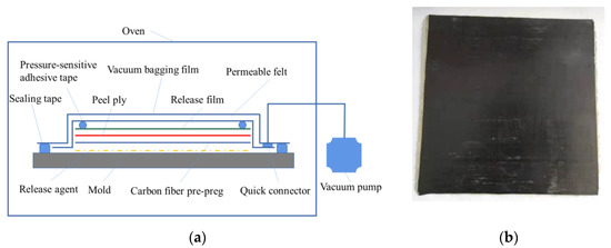
Figure 1.
Fabrication of the CFRP laminate: (a) Schematic of vacuum-assisted resin infusion process; (b) CFRP laminate.
2.2. Mechanical Properties Test of CFRP
The fabricated CFRP laminates were cut into tensile and compressive specimens with 0° and 90° stacking angles, respectively. At the same time, the laminates with 45°/−45° stacking angles were made into in-plane shear specimens. In order to prevent relative sliding between the specimen and the fixture, the resin strengthening sheets were bonded on both sides of the specimen to increase the clamping force. The size of each specimen is shown in Table 2. l1 and l2 are the length of the specimen and epoxy tab; h1 and h2 are the thickness of the specimen and epoxy tab; b is the width of the specimen.
Table 2.
Specimen specification.
The mechanical properties of CFRP were tested using an electronic universal material testing machine. The loading velocity of the tensile, compressive and in-plane shear tests were set as 2 mm/min, 1.3 mm/min and 2 mm/min, respectively. The tensile specimens and test process of CFRP are shown in Figure 2. The calculated mechanical parameters of CFRP are shown in Table 3.
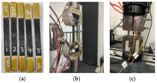
Figure 2.
Mechanical tests of CFRP: (a) tensile specimens; (b) tensile test; (c) compression test.
Table 3.
Mechanical parameters of CFRP.
3. Quasi-Static Axial Crushing Test and Numerical Simulation
3.1. Crashworthiness Evaluation Index
The energy absorption characteristics can be evaluated by the total energy absorption (EA), specific energy absorption (SEA), peak crushing force (PCF), average load (Fmean) and crushing force efficiency (CFE).
- (1)
- The total energy absorption is the total energy absorbed by the thin-walled tube during the crushing process, which can be obtained by calculating the integral of the load in the compression displacement range. The calculation formula is:where l is the crushing distance of the thin-walled tube, and F is the instantaneous crushing force of the thin-walled tube in the compression process.
- (2)
- Specific energy absorption is the energy absorbed by the unit mass of the thin-walled tube, which is an important index to evaluate the energy absorption ability of the structure. The calculation formula is:where m is the mass of the crushed thin-walled tube.
- (3)
- The peak crushing force is the maximum crushing force of the thin-walled tube in the crushing process, which usually appears at the initial stage of the thin-walled tube crushing, and represents the threshold value of the structure damage.
- (4)
- The average load represents the absorbed energy within the unit crushing distance:
- (5)
- The crushing force efficiency is used to evaluate load fluctuation during the crushing process of the thin-walled tube. The larger the crushing force efficiency, the smaller the load fluctuation, indicating that the energy absorption performance of the thin-walled tube is better. The calculation formula can be expressed as follows:
3.2. Specimen Fabrication
In the fabrication process of CFRP thin-walled circular tubes, the unidirectional carbon fiber/epoxy resin pre-preg was rolled onto the suitable inner core mold, according to the required ply angle, thickness and stacking sequence. Then, it was cured in the oven. After demolding and cutting, the CFRP circular tube specimens were obtained. The carbon fiber/epoxy resin pre-preg was coated on the outside of an Al tube to fabricate the CFRP-Al hybrid tube specimen. Three types of tubes, i.e., Al tubes, CFRP tubes and CFRP-Al hybrid tubes, were fabricated, as shown in Figure 3. The specifications of the specimens are listed in Table 4.
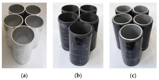
Figure 3.
Three types of thin-walled circular tubes: (a) Al tubes; (b) CFRP tubes; (c) CFRP-Al tubes.
Table 4.
Specifications of the circular tubes.
3.3. Quasi-Static Axial Crushing Test
The quasi-static axial crushing test was carried out using an electronic universal testing machine. The loading velocity was set as 2 mm/min and the compression distance was set as 70 mm. The failure modes of three types of the thin-walled tubes after the quasi-static crushing test are shown in Figure 4, and the load–displacement curves obtained from the tests are shown in Figure 5.
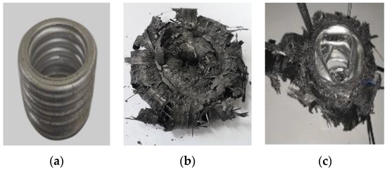
Figure 4.
Failure modes of three types of circular tubes after quasi-static crushing tests: (a) Al tubes; (b) CFRP tubes; (c) CFRP-Al tubes.
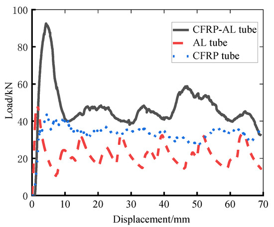
Figure 5.
Load–displacement curves obtained from quasi-static crushing tests.
It can be seen from the above figures that during the crushing process of Al tubes, after reaching the initial peak crushing force, steady-state progressive plastic deformation occurs, resulting in an accordion failure mode. The CFRP circular tube absorbs energy mainly through the fiber fracture, matrix failure and interlayer fracture. With the increase in the compression distance, the CFRP tube is gradually stratified into the inner and outer layers. The outer layer of the CFRP circular tube is torn and rolled out, whereas the inner layer is bent and fractured, forming a “flowering” failure mode. The failure mode of the inside Al tube of the CFRP-Al hybrid tube is diamond failure. Bending failure and brittle fracture of the fiber occur in the outside CFRP layer, and the generated debris filled in the metal folds. Guided by the plastic deformation of the aluminum tube, the failure process of the CFRP-Al hybrid tube is more stable than that of the CFRP tube.
According to the quasi-static axial crushing test results, the energy absorption performance evaluation indexes of the three types of tubes are calculated, as shown in Table 5. It can be seen that the specific energy absorption and crushing force efficiency of the CFRP circular tube are higher than those of the Al circular tube and CFRP-Al hybrid circular tube. The crashworthiness of the CFRP-Al circular tube is also better than that of the Al tube, indicating that the carbon-fiber-reinforced plastics have better energy absorption capacity.
Table 5.
Evaluation indexes of energy absorption characteristics for the three types of circular tubes.
3.4. Finite Element Model
Finite element models of the three types of the thin-walled circular tubes for the quasi-static axial crushing simulation were established. The Al tube and the CFRP tube were simulated using the single shell, whereas the CFRP-Al hybrid tube was modeled by the double shell method. The axial crushing finite element model is shown in Figure 6. The basic mechanical property parameters of the Al alloy are listed in Table 6.
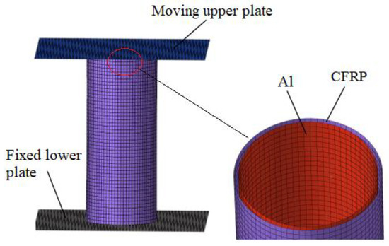
Figure 6.
Finite element model of the CFRP-Al hybrid circular tube.
Table 6.
Mechanical property parameters of Al alloy.
In the quasi-static axial crushing finite element models of the thin-walled circular tubes, the lower plate is fixed, whereas the upper plate can move along the axial direction. LS-DYNA was used to perform the finite element simulation of the axial crushing. MAT20 was used for the material model of the upper and lower plates, which were taken as rigid parts. MAT24 and MAT54 were adopted to define the material properties of the Al tube and CFRP tube, respectively. MAT54 is a progressive failure model, which utilizes the Chang–Chang failure criterion based on stress description [25], and its expression is:
- (1)
- Fiber tensile failure (σ1 > 0):
- (2)
- Fiber compression failure (σ1 > 0):
- (3)
- Matrix tensile failure (σ2 > 0):
- (4)
- Matrix compression failure (σ2 < 0):where σ1, σ2 and τ12 represent the axial stress, transverse stress and shear stress, respectively. Equations (1)–(3) denote the fiber longitudinal direction, transverse direction and thickness direction, respectively. Xt and Xc are the longitudinal tensile and compressive strength of the fiber, respectively. Yt and Yc are the transverse tensile and compressive strength, respectively. Sc is the in-plane shear strength.
3.5. Numerical Simulation
The axial compression velocity and the compression displacement for the axial crushing simulations of the three types of tubes were set as 2 mm/min and 70 mm, respectively. Then, the quasi-static axial crushing simulations were carried out based on the finite element models. The simulation results of the Al tube, CFRP tube and CFRP-Al hybrid tube were compared with their experimental results, as shown in Figure 7, Figure 8 and Figure 9.
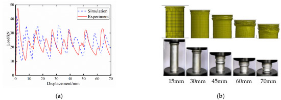
Figure 7.
Simulation and experiment comparison of the Al tube: (a) load–displacement curve; (b) comparison of deformation modes.
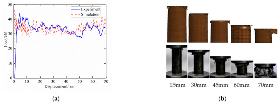
Figure 8.
Simulation and experiment comparison of the CFRP tube: (a) load–displacement curve; (b) comparison of deformation modes.
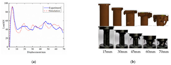
Figure 9.
Simulation and experiment comparison of the CFRP-Al hybrid tube: (a) load–displacement curve; (b) comparison of deformation modes.
Based on the above comparative analysis results, it can be seen that the finite element simulation and experiment of the Al tubes are both accordion failure modes, and six relatively complete folds are formed after collapse failure. The simulation results of the load–displacement curves are basically consistent with the experimental results. The simulation value of the first peak crushing force is slightly smaller than the experimental value, and their average loads are close, which indicates that the established finite element model can accurately simulate the axial compression deformation behavior of the Al tube.
The single-layer shell modeling method was adopted in the CFRP circular tube; therefore, there was no obvious “flowering” failure mode in the simulation. It mainly manifested as bending and cracking in the tube. In the simulation process, the deletion of the failure elements caused a sudden drop in the bearing capacity of the circular tube, which made the simulation results fluctuate greatly in the load–displacement curve. In addition, the upper end of the experiment specimen was set with a 45° chamfer, so that the first peak crushing force of the experiment curve occurs later than that of the simulation results. However, in general, the simulation results are close to the experiment results, and the average load is not much different.
Both the simulation model and experiment specimen of CFRP-Al hybrid circular tubes exhibited progressive failure. The outer CFRP circular tube cracked outward in the form of clusters, and the inner Al tube gradually changed from accordion failure to diamond failure. The outer CFRP tube absorbed energy mainly through the delamination failure and fiber fracture, whereas the inner Al tube absorbed energy mainly through plastic deformation. The failure mode of the simulation and experiment had high consistency. At the same time, the simulation results of the axial crushing force were basically consistent with the experimental results, indicating that the finite element model can accurately simulate the quasi-static axial crushing behavior of the CFRP-Al hybrid tube.
The energy absorption evaluation indexes of the three types of thin-walled tubes were calculated from the experiment results and simulation results, as shown in Figure 10. It can be seen that the simulation values of the peak crushing force (PCF) and crushing force efficiency (CFE) of the Al tube were quite different from the experimental values, which is because the simulation model did not set a chamfer at the upper end. The ply thickness of the CFRP tube specimen was different from that of the CFRP-Al hybrid tube specimen due to the fabrication process. The ply thickness of the finite element models of the CFRP tube and the CFRP-Al tube were both determined by the thickness of the CFRP layer of the CFRP-Al tube specimen, to ensure the accuracy of the finite element model of the CFRP-Al hybrid tube. Thus, the error between the simulation value and the experimental value of the specific energy absorption (SEA) of the CFRP tube was large, because the ply thickness of the CFRP tube model had an error in the actual value, resulting in a large mass difference. The errors in all the energy absorption indexes of the CFRP-Al hybrid circular tube were small, indicating that the established finite element model of the CFRP-Al hybrid circular tube had high accuracy.
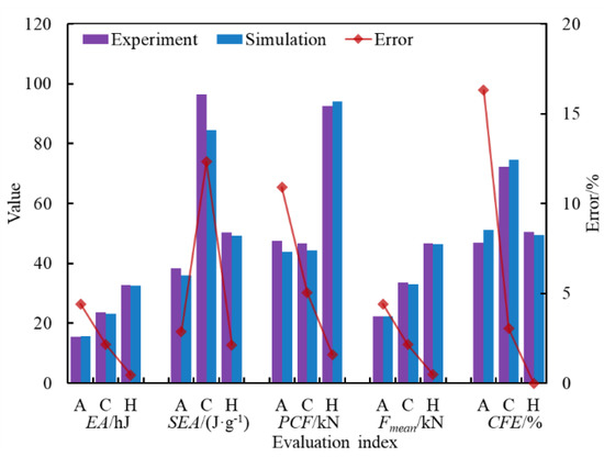
Figure 10.
Comparison of evaluation indexes of energy absorption characteristics between the simulation and experiment.
4. Energy Absorption Characteristics Analysis of a CFRP-Al Hybrid Circular Tube
4.1. Orthogonal Design
The energy absorption characteristics of the CFRP-Al hybrid thin-walled circular tube are closely related to the structure and material parameters. In order to study the influence of geometric size and ply parameters on the energy absorption characteristics of the CFRP-Al hybrid circular tube, the orthogonal experimental design method was used to arrange the finite element simulations, which could save calculation resources. The Al tube thickness (TA), single ply thickness of the CFRP tube (TC), diameter of interface between the CFRP tube and Al tube (D), length of hybrid tube (L) and ply angle of the CFRP tube (A) were defined as factors. Five levels of each factor were chosen, and the level values of the factors were given in Table 7. The orthogonal table L25(56) was adopted to arrange the simulations, and the simulation schemes are listed in Table 8.
Table 7.
Levels of different factors.
Table 8.
Orthogonal array.
According to the orthogonal table, the finite element simulations of 25 groups of the design schemes were carried out. Then, the energy absorption evaluation indexes of each scheme were calculated. The influence of the factors on different energy absorption indexes was different. Thus, it is difficult to determine the influence law. It is necessary to determine a comprehensive index to evaluate the energy absorption characteristics of the CFRP-Al hybrid circular tube.
4.2. Entropy-Weighted TOPSIS
The TOPSIS method can transform multi-response problems into a single-response problem [26,27]. According to the closeness between the evaluation object and the idealized target, the order is arranged to determine the best scheme. The decision matrix of the TOPSIS method can be expressed as
where xij (i = 1, 2, ..., m. j = 1, 2, ..., n) denotes the jth energy absorption index of group i scheme. m is the number of orthogonal design schemes. n is the number of energy absorption evaluation indexes.
To eliminate dimension effect, the decision matrix is regularized:
where rij represents the regularization result of xij.
Information entropy can evaluate the degree of disorder of the system. The smaller the information entropy, the more information it can provide; the greater the impact on the comprehensive evaluation, the higher the weight should be. The calculation formula of the information entropy ej is:
where k is the adjustment coefficient. pij represents the normalization result after rij.
The calculation formula of the weight coefficient of each performance index is:
Considering the weight coefficient of each performance index, the regularization result rij is weighted as:
where wj represents the weight coefficient of the jth energy absorption index.
The TOPSIS method ranks each scheme according to the distance between it and the ideal solution. The ideal solution and negative ideal solution are defined as:
where A+ and A− represent the ideal solution set and the negative ideal solution set, respectively.
The larger the energy absorption, specific energy absorption, average load and crushing force efficiency of the CFRP-Al hybrid circular tube, the better the energy absorption performance. Therefore, the calculation methods of the ideal solution and negative ideal solution are as follows:
For the peak crushing force of the CFRP-Al hybrid circular tube, the smaller the value, the better it is. Therefore, the calculation method of the ideal solution and negative ideal solution are expressed as:
where and denote the ideal solution and negative ideal solution under the jth performance index, respectively.
The distances between each scheme and the ideal solution and negative ideal solution are calculated by Euclidean distance, formulated as follows:
where and denote the distance between the ith scheme and the ideal solution and negative ideal solution, respectively.
The energy absorption performance of each scheme can be evaluated by the relative proximity coefficient, which is formulated as:
where Ci represents the relative proximity coefficient of the ith scheme, and the larger the value, the better the scheme
The influence of the structure and material parameters of the CFRP-Al hybrid tube on its energy absorption characteristics can be studied based on the orthogonal design and entropy-weighted TOPSIS. The analysis flowchart of the crashworthiness of CFRP-Al hybrid thin-walled circular tubes can be summarized as shown in Figure 11.
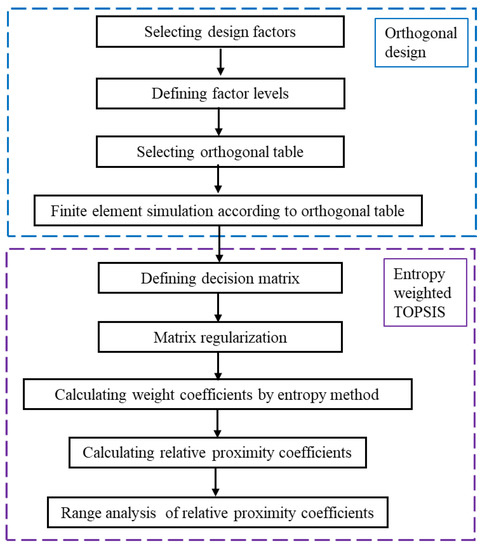
Figure 11.
Flowchart of crashworthiness analysis of CFRP-Al hybrid tubes.
4.3. Energy Absorption Characteristics of a CFRP-Al Hybrid Tube
The weight coefficients of each evaluation index of energy absorption characteristics of the CFRP-Al hybrid tube are calculated by the entropy-weighting method, as shown in Table 9. The relative proximity coefficients of the 25 simulation schemes are calculated, as shown in Figure 12.
Table 9.
Weight coefficients of energy absorption indexes.
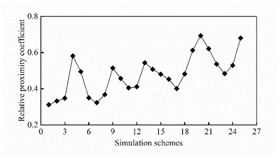
Figure 12.
Relative proximity coefficient for each simulation scheme.
According to the layout of the orthogonal table, the range analysis of the relative proximity coefficients of the above simulation schemes was carried out. Then, the influence of geometric parameters and CFRP ply parameters on the energy absorption performance of the CFRP-Al hybrid circular tube was studied. The main effect diagram is shown in Figure 13.
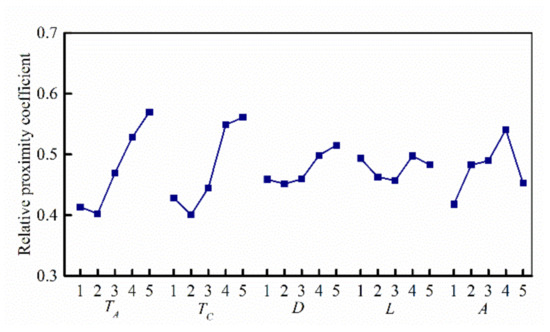
Figure 13.
Main effect diagram of levels for each factor of the CFRP-Al hybrid tube.
It can be seen that the thickness of the Al tube (TA), the ply thickness of the CFRP tube (TC) and the ply angle (A) have a large rangeability, indicating that the three factors have a high influence on the energy absorption performance of the CFRP-Al hybrid circular tube. With the increase in the Al tube thickness and CFRP ply thickness, the energy absorption performance of the CFRP-Al hybrid tube is improved. The optimal stacking angle is [0°, 45°, −45°, 90°]2. The diameter of the contact surface (D) and the length of the hybrid tube (L) changed smoothly with the increase in the level, which means their influence on the energy absorption of the CFRP-Al hybrid tube is relatively small.
According to the influence degree from large to small, it can be ranked as the thickness of the Al tube, the ply thickness of the CFRP tube, the ply angle of the CFRP tube, the diameter of the contact surface and the length of the hybrid tube.
5. Conclusions
(1) Quasi-static axial crushing tests of Al circular tubes, CFRP circular tubes and CFRP-Al hybrid circular tubes were carried out. The energy of the Al tube was mainly absorbed by the folds generated in the crushing process. The energy of the CFRP circular tube was mainly absorbed by the fiber fracture, matrix failure and delamination. The CFRP-Al hybrid circular tube guided the progressive failure of CFRP by the plastic deformation of the Al circular tube, and the energy absorption process was more stable than that of the CFRP tube.
(2) The specific energy absorption and crushing force efficiency of the CFRP circular tube are higher than those of the Al tube and CFRP-Al hybrid tube. The energy absorption performance of the CFRP-Al hybrid tube is better than that of the Al tube. Compared with metal materials, CFRP has a better energy absorption capacity.
(3) The finite element model of the Al tube established by a single shell can accurately simulate its crushing failure mode. However, the simulation results of the peak crushing force and crushing force efficiency are relatively large due to the fact that the finite element model lacks the failure guide chamfer. The finite element model of the CFRP circular tube cannot simulate the delamination failure mode, but it can accurately simulate and calculate most energy absorption performance indexes. The finite element model of the CFRP-Al hybrid circular tube established by a double shell has high accuracy and can accurately simulate its quasi-static axial crushing behavior.
(4) Entropy-weighted TOPSIS method can convert multiple energy absorption indexes into a comprehensive evaluation index, which is adopted to analysis the influence of the structure and material parameters on the energy absorption characteristics of the CFRP-Al hybrid circular tube. The results show that the thickness of the Al tube and the ply thickness and stacking angle of the CFRP tube have great influence on the energy absorption performance of the hybrid tube. Increasing the thickness and the number of 45° stacking plies can improve the energy absorption capacity of the hybrid tube, whereas the diameter and length of the circular tube have little influence.
Author Contributions
Conceptualization, R.J., Z.G. and T.Z.; methodology, R.J. and Z.G.; resources, D.L. and H.S.; software, R.J., T.Z. and D.P.; validation, R.J. and Z.G.; writing—original draft preparation, R.J., Z.G., D.L. and Z.P.; writing—review and editing, R.J., D.L., H.S., Z.P. and D.P. All authors have read and agreed to the published version of the manuscript.
Funding
This research was funded by National Natural Science Foundation of China (grant no. 51805286) and Shandong Province Natural Science Foundation (grant no. 2017PEE004).
Conflicts of Interest
The authors declare no conflict of interest.
References
- Baroutaji, A.; Sajjia, M.; Olabi, A. On the crashworthiness performance of thin-walled energy absorbers: Recent advances and future developments. Thin-Walled Struct. 2017, 118, 137–163. [Google Scholar] [CrossRef] [Green Version]
- Liu, Y.; He, Y.; Liu, S.; Li, Z. Energy absorption capacity of regular polygon-based multi-cell tubes. Explos. Shock. Waves 2020, 40, 38–46. [Google Scholar]
- Wang, Y.; Wu, Z.; Liu, F. Crush experiment of composite cargo floor stanchions. Acta Mater. Compos. Sin. 2020, 37, 2200–2206. [Google Scholar]
- Chen, J.; Xu, S.; Liu, Z.; Tang, A.; Li, W. Lightweight Optimization of Aluminum Alloy Energy Absorbing Box for Crash Safety. Automot. Eng. 2021, 43, 241–247. [Google Scholar]
- Wang, Z.; Song, K.; Zhu, G.; Cheng, A. Axial energy absorption characteristics of unidirectional carbon-fiber composite cone tubes. J. Vib. Shock. 2018, 37, 172–178. [Google Scholar]
- Zhu, G.; Yu, Q.; Zhao, X.; Wei, L.; Chen, H. Energy-absorbing mechanisms and crashworthiness design of CFRP multi-cell structures. Compos. Struct. 2020, 233, 111631. [Google Scholar] [CrossRef]
- Cheng, Q.; Xu, Y.; Liao, J.; Fang, Z.; Yi, X. Effects of triggers on the energy absorption behavior of sine-wave beam and the crush morphology. Acta Mater. Compos. Sin. 2008, 25, 161–167. [Google Scholar]
- Feng, Z.; Zhao, Y.; Chen, Y.; Xie, J. Evaluation method for energy-absorbing composite structures with uncertain parameters. J. Vib. Shock. 2015, 34, 109–114. [Google Scholar]
- Wang, K.; Ma, Q.; Zha, Y. The influence of end induced holes on axial compression performance of Al-CFRP composite thin-walled tube. Compos. Sci. Eng. 2021, 0, 65–71. [Google Scholar]
- Yu, H.; Shi, H.; Chen, S. Simulation method for CFRP/AA6061 thin-walled structure subjected to axial crushing. Trans. Beijing Inst. Technol. 2019, 39, 1026–1033. [Google Scholar]
- Shen, Y.; Ke, J.; Wu, Z. Energy-absorbing characteristics of carbon fiber reinforced polymer compo-site-Al square tubes with different braiding angles. Acta Mater. Compos. Sin. 2020, 37, 591–600. [Google Scholar]
- Feng, P.; Hu, L.; Qian, P.; Ye, L. Compressive bearing capacity of CFRP–aluminum alloy hybrid tubes. Compos. Struct. 2016, 140, 749–757. [Google Scholar] [CrossRef]
- Kalhor, R.; Akbarshahi, H.; Case, S.W. Numerical modeling of the effects of CFRP thick-ness and stacking sequence on energy absorption of metal-CFRP square tubes. Compos. Struct. 2016, 147, 231–246. [Google Scholar] [CrossRef]
- Reuter, C.; Troster, T. Crashworthiness and numerical simulation of hybrid aluminum/CFRP tubes under axial impact. Thin-Walled Struct. 2017, 117, 1–9. [Google Scholar] [CrossRef]
- Zhu, G.; Sun, G.; Liu, Q.; Li, G.; Li, Q. On crushing characteristics of different configurations of metal-composites hybrid tubes. Compos. Struct. 2017, 175, 58–69. [Google Scholar] [CrossRef]
- Zhu, G.; Sun, G.; Yu, H.; Li, S.; Li, Q. Energy absorption of metal, composite and metal/composite hybrid structures under oblique crushing loading. Int. J. Mech. Sci. 2018, 135, 458–483. [Google Scholar] [CrossRef]
- Sun, G.; Wang, Z.; Hong, J.; Song, K.; Li, Q. Experimental investigation of the quasi-static axial crushing behavior of filament-wound CFRP and aluminum/CFRP hybrid tubes. Compos. Struct. 2018, 194, 208–225. [Google Scholar] [CrossRef]
- Yang, H.; Lei, H.; Lu, G. Crashworthiness of circular fiber reinforced plastic tubes filled with composite skeletons/aluminum foam under drop-weight impact loading. Thin-Walled Struct. 2021, 160, 107380. [Google Scholar] [CrossRef]
- Zhu, G.; Zhao, Z.; Hu, P.; Luo, G.; Zhao, X.; Yu, Q. On energy-absorbing mechanisms and structural crashworthiness of laterally crushed thin-walled structures filled with aluminum foam and CFRP skeleton. Thin-Walled Struct. 2021, 160, 107390. [Google Scholar] [CrossRef]
- Jiang, R.; Zhang, T.; Sun, H.; Liu, D.; Chen, H.; Wang, D. Study on lightweighting of CFRP bumper beam using entropy-based TOPSIS approach. Automot. Eng. 2021, 43, 421–428. [Google Scholar]
- Wang, D.; Jiang, R.; Wu, Y. A hybrid method of modified NSGA-II and TOPSIS for lightweight design of parameterized passenger car sub-frame. J. Mech. Sci. Technol. 2016, 30, 4909–4917. [Google Scholar] [CrossRef]
- Ni, H.; Yan, C.; Chen, J.; Hou, Y.; Chen, L. Multi-objective optimization and decision-making method of high speed dry gear hobbing processing parameters. China Mech. Eng. 2021, 32, 832–838. [Google Scholar]
- Pirmohammad, S.; Ahmadi-Saravani, S.; Zakavi, S.J. Crashworthiness optimization design of foam-filled tapered decagonal structures subjected to axial and oblique impacts. J. Cent. South Univ. 2019, 26, 2729–2745. [Google Scholar] [CrossRef]
- Ebrahimi-Nejad, S.; Kheybari, M.; Borujerd, S.V.N. Multi-objective optimization of a sports car suspension system using simplified quarter-car models. Mech. Ind. 2020, 21, 412. [Google Scholar] [CrossRef]
- Feraboli, P.; Wade, B.; Deleo, F.; Rassaian, M.; Higgins, M.; Byar, A. LS-DYNA MAT54 modeling of the axial crushing of a composite tape sinusoidal specimen. Compos. Part A Appl. Sci. Manuf. 2011, 42, 1809–1825. [Google Scholar] [CrossRef]
- Jiang, R.; Liu, D.; Wang, D. Multi-objective optimization of vehicle dynamics performance based on entropy weighted TOPSIS method. J. Mech. Eng. 2018, 54, 150–158. [Google Scholar] [CrossRef] [Green Version]
- Jiang, R.; Ci, S.; Liu, D.; Cheng, X.; Pan, Z. A Hybrid Multi-Objective Optimization Method Based on NSGA-II Algorithm and Entropy Weighted TOPSIS for Lightweight Design of Dump Truck Carriage. Machines 2021, 9, 156. [Google Scholar] [CrossRef]
Publisher’s Note: MDPI stays neutral with regard to jurisdictional claims in published maps and institutional affiliations. |
© 2021 by the authors. Licensee MDPI, Basel, Switzerland. This article is an open access article distributed under the terms and conditions of the Creative Commons Attribution (CC BY) license (https://creativecommons.org/licenses/by/4.0/).