Article

Thermal Stability of Type II Modifications Inscribed by Femtosecond Laser in a Fiber Drawn from a 3D Printed Preform

1
French National Centre for Scientific Research, ICMMO (SP2M/MAP), Université Paris-Saclay, 91405 Orsay CEDEX, France
2
Photonics and Optical Communications, School of Electrical Engineering and Telecommunications, University of New South Wales, Sydney, NSW 2052, Australia
3
Interdisciplinary Photonics Laboratories, Global Big Data Technologies Centre (GBDTC), School of Electrical & Data Engineering, University of Technology Sydney, Sydney, NSW 2007, Australia
*
Authors to whom correspondence should be addressed.
Appl. Sci. 2021, 11(2), 600; https://doi.org/10.3390/app11020600
Submission received: 23 November 2020 / Revised: 5 January 2021 / Accepted: 6 January 2021 / Published: 9 January 2021
(This article belongs to the Special Issue Silica-Based Optical Fibers Technologies)

Abstract

:
Fiber drawing from a 3D printed perform was recently discussed to go beyond the limitations of conventional optical fiber manufacturing in terms of structure and materials. In this work, the photosensitivity of silica optical fibers to femtosecond laser light, and fabricated by 3D printing a preform, is investigated. The writing kinetics and the thermal performance of Type II modifications are studied by varying the laser pulse energy and investigating the birefringence response of the femtosecond (fs)-laser written structures. Compared with a conventional telecom single mode fiber (SMF28), the fiber made by 3D printing is found to have similar writing kinetics and thermal performance. Additionally, the thermal stability of the imprinted fs-laser induced nanostructures is investigated based on the Rayleigh–Plesset equation, describing a model of nanopores dissolution underpinning Type II modifications with thermal annealing.

1. Introduction

Silica optical fiber is the backbone of optical fiber communication networks, permitting signal transmission over long distances at high bandwidth. Since the 1970s numerous methods were explored in the development of low loss silica telecom fibers, most involving the fabrication of preforms from which fiber is subsequently drawn [1]. The most successful processes have been variations of chemical vapor deposition (CVD) [2]. With the development of optical fiber technology, the focus has gradually included increasing specialization of the fiber for components such as fiber Bragg grating (FBG) sensors, lasers, and amplifiers. Ideally optical fiber fabrication has to remain compatible with standard low-loss fiber as well as opening the door to novel functionalities. Nevertheless, conventional fabrication methods such as CVD and rod-in-tube stacking, have limited capability in both material and structure flexibility for diverse and custom-designed functionalities [3,4,5]. To address these limitations a new alternative is the use of additive manufacturing in the fabrication of preforms from which fiber is drawn [6,7].
The early work in this field was on 3D printing plastic fibers [6], followed by 3D printed silica-based fiber preform fabrication [7]. 3D silica printing allows greater freedom in both structure and material design and choice. This fabrication process will be a major disruption more broadly because it reduces the skill requirements typically required in CVD processes and reduces overall costs whilst enabling newer designs. Therefore, it is important to better understand and compare these new fibers against their equivalent counterpart produced by conventional means. One important comparison that provides insights into the quality of glass in these fibers is assessing photosensitivity. This can be done by creating a refractive index grating in the core of an optical fiber using optical irradiation, a process that underpins fiber Bragg gratings (FBG) inscription and application, demonstrating both scientific and practical significance [8].
Among various types of FBGs, Type II-fs-IR-FBGs, inscribed by femtosecond near-infrared (fs-IR) irradiation, have drawn great attention, due to their notable thermal stability at T~1000 °C for at least several hours and even 100 h at this temperature after stabilization in SMF28(single mode fiber) fibers [9,10]. In addition, it has been shown that the thermal stability of these Type II modifications is affected by writing and fabrication conditions. For example, by increasing the writing speed, the reflectivity of Type II fs-IR FBGs is found to be more resistant to higher temperatures [11]. It has also been reported that the thermal performance of FBGs can be influenced by varying pulse energy or repetition rate [12]. Unlike Type I-fs-IR-FBGs where the refractive index changes are positive with respect to the non-irradiated region and could only be used up to T~800 °C [13], Type II fs-IR FBGs, associated with a high level of anisotropic index change, are attributed to the formation of self-organized nanogratings [14] made through glass oxide decomposition [15]. These nanostructures are composed of regularly spaced porous nanolayers with nanopores typically a few tens of nm in size [15,16]. Due to their periodic subwavelength nanostructure, the Type II modifications are birefringent, and therefore the optical retardance R can be monitored to investigate the thermal stability of our object.
Thus, to explore the photosensitivity of optical fibers fabricated from preforms produced by additive manufacture, an fs-IR laser was used to create changes within the fiber, henceforth termed “3D printed fiber”. The laser-induced birefringence is measured at different pulse energies. Then the thermal stability of these fs-IR laser inscribed structures (Type II modifications) was evaluated through multiple isochronal annealing cycles. For comparison, similar experiments were performed on conventional silica SMF28 optical fiber (from Corning) and will serve as a reference throughout this work. Finally, the porous nanostructures, induced by Type II modifications in silica glass are stable at high temperatures (>1000 °C). To investigate their high-temperature stability behavior, isochronal annealing is performed on irradiated fiber samples, and the birefringent response is monitored. Following this, the Rayleigh–Plesset (R-P) equation is used to fit the data [16].

2. Experimental Setup

2.1. Fiber Manufacturing

A brief overview of the process for 3D printed fibers is shown in Figure 1. It can be divided into five steps, and are described in short. (1) First, a photocurable resin was fabricated by mixing 2-phenoxyethanol (POE), 2-hydroxyethyl methacrylate (HEMA), diphenyl(2,4,6-trimethylbenzoyl) phosphine oxide (DPO), tetra(ethylenglycol) diacrylate (TEGDA), and hydroquinone (Hyd), (all purchased from Sigma-Aldrich, Australia), which is a photoresin provided for use with digital light processing (DLP) 3D printer. Then, high purity silica glass nanoparticles (purchased from Evonik, Australia) were dispersed in the resin and sued in printing. (2) The optical fiber cladding preform was designed by Inventor CAD (the targeted cladding diameter was ϕ = 125 µm) and then fabricated using a DLP 3D printer (Asiga Freeform Pro 2 75 UV; x,y pixel resolution ~75 µm, Asiga, Sydney, Australia). (3) To make the preform core, germanium oxide (GeO2) powder was added into the previously mixed resin. This increases the refractive index of the mix. The resin was subsequently injected into the cladding preform. (4) With high temperature heating, the preform undergoes thermal debinding above 300 °C to remove the polymer resin, leaving only a silica structure. (5) Finally, the preform is inserted into a supporting silica tube and placed inside a draw tower and drawn into fiber (L~2–3 km, cladding diameter ~125 µm) at a temperature T~1900 °C. More details of the fabrication process can be found in References [6,7,17].

2.2. Optical Fiber Characterization

After drawing, fiber segments are selected to investigate the core-cladding geometry, as well as the core radial distribution of the GeO2 dopant. A highly asymmetric fiber core is observed in Figure 2 (inset), arising from core distortion during the drawing process where the outer support silica tube used required a temperature higher than optimal for the interior Fused Deposition Modeling (FDM) preform. The printed preform was not transversally uniform leading to stresses that distorted the softer germanosilicate core producing the observed twisted elliptical shape (long axis ϕ~4 µm, short axis ϕ~2 µm; they are not orthogonal suggesting elliptical birefringence). These were recorded using a ZEISS SUPRA 55 VP scanning electron microscope (SEM). This 3D printed preform drawn silica fiber has a germanosilicate core and silica cladding. Dopant distributions were measured with energy dispersive x-ray analysis (EDX) and shown in Figure 2 along one axis of the fiber. Compared to SMF28, the core size of the 3D printed fiber is smaller with (GeO2) ~10 mol %, almost twice as much as SMF28, though less than commercial photosensitive fibers such as Nufern’s GF1 ((GeO2)~33 mol %). No evidence of polymer or water from the resin preform was detected using FTIR spectroscopy.

2.3. Laser Writing Experiments

Two fiber segments (one for 3D-printed and one for SMF28) were selected, each one having a length L~6–8 cm long. Their polymer coating was removed, and a high temperature adhesive was used to attach them onto a silica thin slide. A borosilicate glass coverslip (170 μm thin) was placed on top of the fiber segments, with some index-matching oil (GN Nettest, nD = 1.4580 at T = 25 °C) introduced between the silica and the borosilicate slides, to facilitate the observation of the core and subsequent laser irradiation. Each sample was then placed on an XYZ motorized translation stage and irradiated using a femtosecond laser (λ = 1030 nm, t = 250 fs). The laser repetition rate was fixed to rr = 100 kHz and the scanning speed to v = 100 µm/s. The laser beam was focused using a 0.6 NA aspheric lens. Geometry similar to a line-by-line FBG writing was performed to investigate the writing kinetics of Type II modifications. As represented in Figure 3a, several lines length L = 60 μm are written, traversing both the core and the cladding. They are written perpendicular to the direction of the fiber longitudinal axis with a linear laser polarization oriented either parallel (labeled Yy configuration,//) or perpendicular (labeled Yx configuration, ⊥) to the scanning direction. The spacing between each line is 5 μm, and the pulse energy Ep (in µJ/pulse) varies between each line in steps of ΔE~0.1 μJ, ranging from Ep = 0.1 to 1.5 μJ. To measure the optical retardance R, an Olympus BX51 polarizing optical microscope equipped with a quarter waveplate was used. The retardance is defined as R = B × L, where B is the birefringence and L is the length of the birefringent object being measured. In this work, the impact of pulse energy on the retardance response is investigated. This provides an indication of the kind of modifications (voids, nanogratings, densification) involved during the irradiation process. The impact of processing parameters such as repetition rate (rr), pulse duration (Δt) and writing speed (v) will be systematically studied in future work.

3. Results

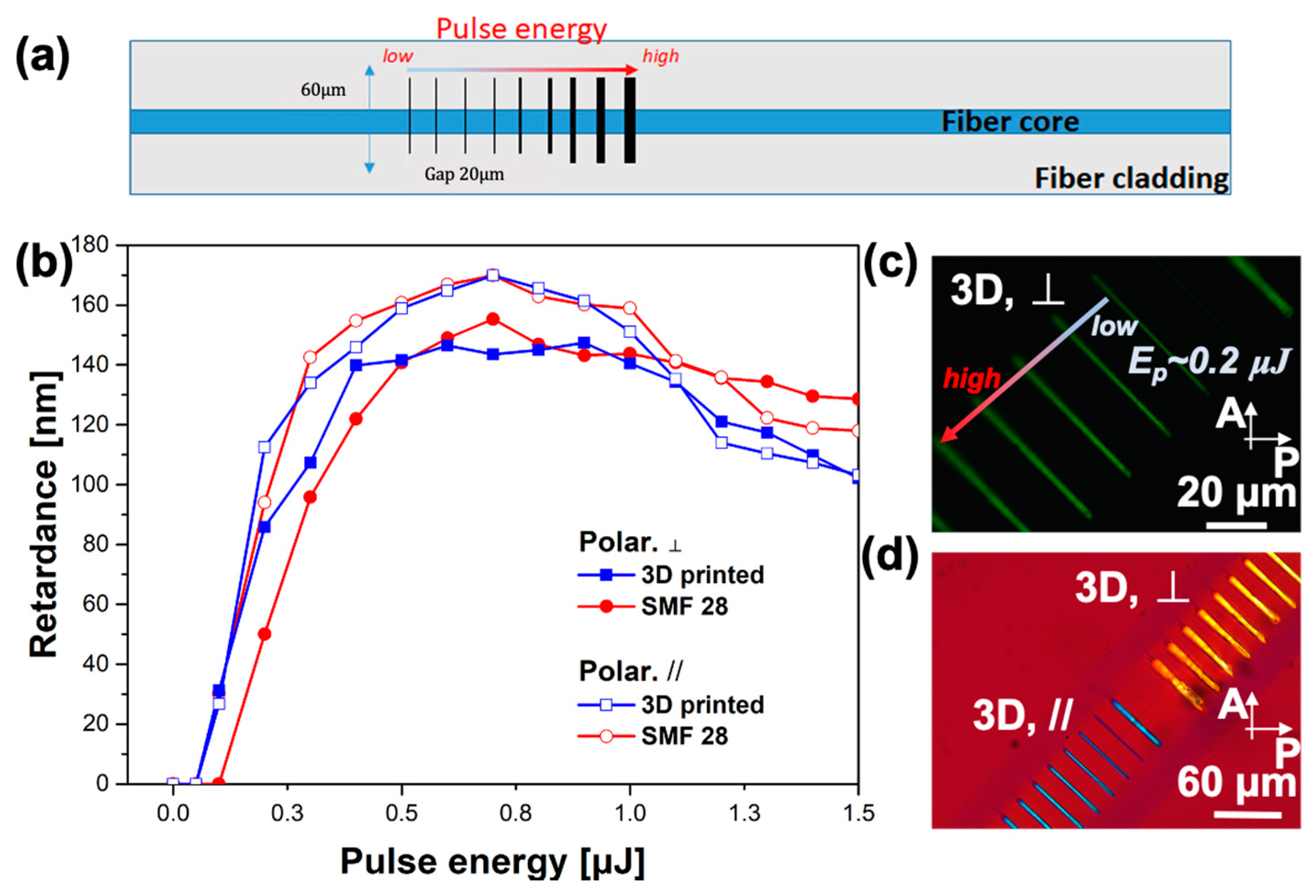
Figure 3b shows the measurements of the retardance, R, as a function of the laser pulse energy for both investigated fibers. We focused on the Type II fs-IR threshold where the optical properties of the irradiated regions are modified. A strong linear birefringence originating from the formation of nanogratings can be detected when the energy exceeds the threshold. Illustrated in Figure 3b, the 3D printed fiber shows a lower Type II threshold than conventional fiber. A well-defined birefringence response appears when the pulse energy is above Ep~0.1 µJ for 3D-printed fiber. For the SMF 28 fiber, the Type II threshold is observed at a laser pulse energy Ep~0.2 µJ. Such variations in Type II threshold could be explained by the higher Ge concentration that leads to higher interface stresses and therefore lower thresholds. Under crossed polarizer and analyzer, the lines appear birefringent when Ep > 0.2 µJ for 3D printed fiber as shown in Figure 3c. Furthermore, the first order (full wave) plate technique [18] was used to detect the slow/fast axis orientation of the photo-induced birefringence (Figure 3d). When the inscribed line slow axis is parallel (perpendicular) to the slow axis of the full wave, the line appears blue (yellow). This is consistent with birefringence that we have observed previously that is related to the formation of nanogratings [19,20], and where the fast axis is oriented parallel to the laser polarization.
Although within error there are small differences between threshold values, R increases as a function of pulse energy in a similar way for both fibers (both in shape and magnitude) as shown in Figure 3b. R values rapidly increased after exceeding a threshold and began to plateau after Ep~0.4 μJ. It should be noted that the retardance is lower for the Yx configuration relative to the Yy configuration. Such polarization dependence is explained by boundary conditions and varying spatial–temporal properties of the ultrashort pulse laser beam. This was quantified with pulse front tilting, leading to anisotropic photosensitivity [21,22]. These results indicate that these 3D printed fibers exhibit analogous photosensitivity compared with SMF28, consistent with similar quality germanosilicate glass. They also suggest that similarly to conventional fibers, applications such as FBGs are possible using 3D printed preform derived optical fibers. This comparative study suggests material quality is comparable despite the large differences in initial preform fabrication. This is a promising result pointing towards a feasible disruption of conventional fiber fabrication using additive manufacturing.
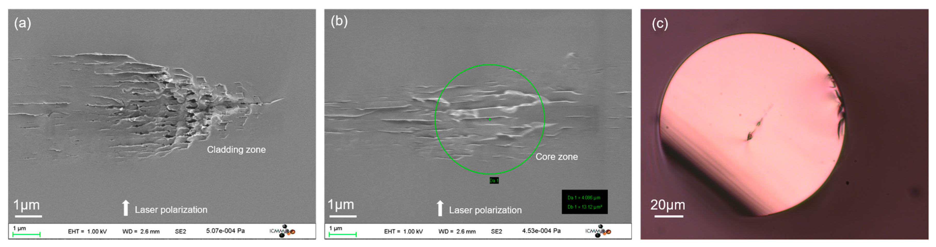
In order to better understand and confirm the origin of the polarization dependent birefringence detected in Figure 3, the fiber segment was simply cleaved by the ceramic fiber scribe and the cross sectional area with the laser polarization ⊥ to the writing direction was directly investigated using an SEM (Field-Emission Gun Scanning Electron Microscope, ZEISS SUPRA 55 VP, 1 kV accelerating voltage, ZEISS, Jena, Germany). Figure 4c shows that the trajectory of the laser perfectly passes through the center of the fiber. As observed in Figure 4a,b, the formation of the nanogratings can be clearly identified in both the cladding and the core zone of the 3D printed fiber. In similar bulk compositions [15], such periodic array of porous nanoplanes separated by non-porous glass leads to the formation of form birefringence [15,20].
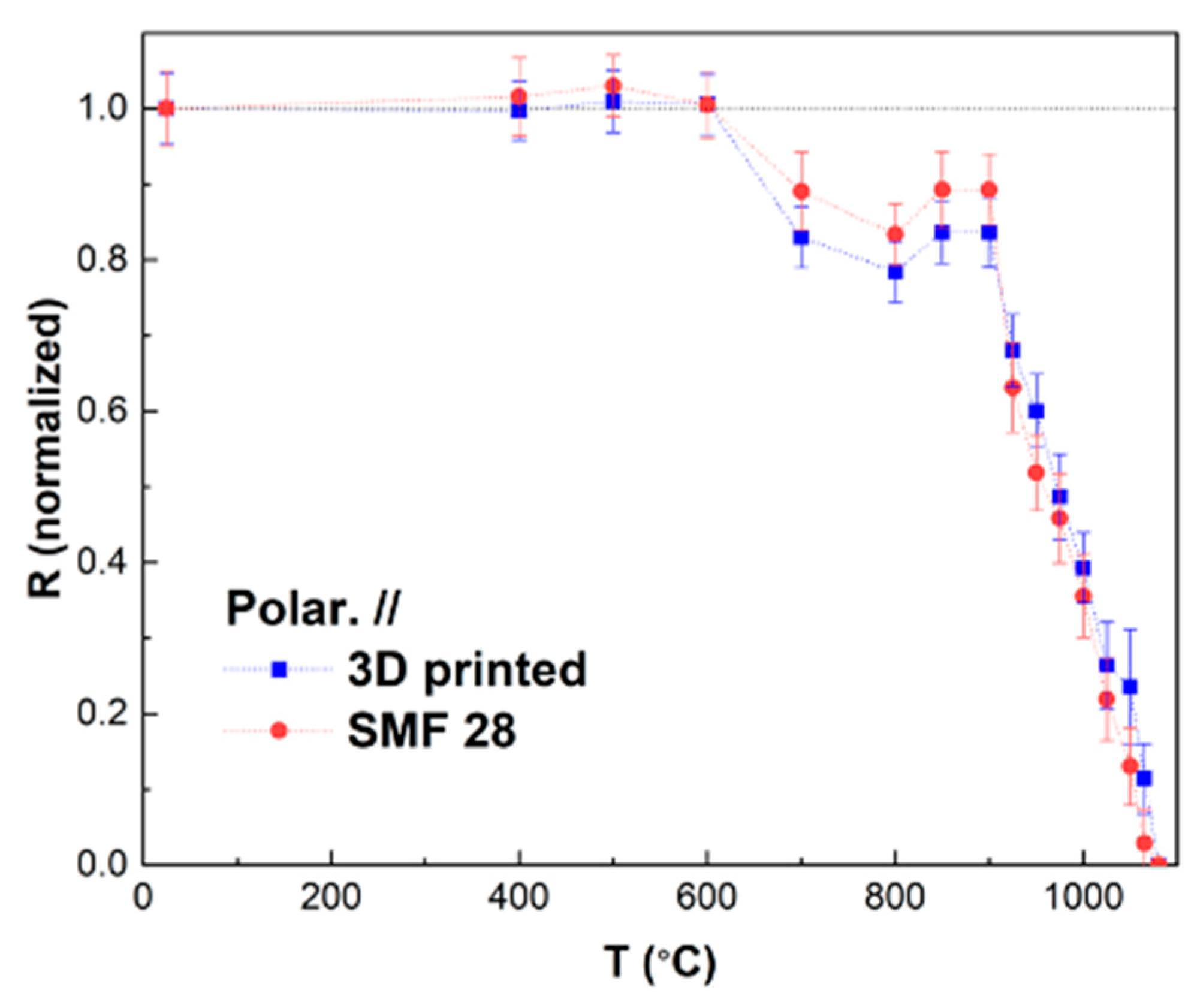
The thermal stability of the fibers was investigated using Δt = 30 min step isochronal annealing up to temperatures T = 1100 °C. In Figure 5, retardance values Rnorm(Δt, T) (normalized with respect to their initial room temperature values R(t = 0, and T = 20 °C)) as a function of annealing temperature for both SMF28 and the 3D printed fiber are displayed. In this figure the comparison between the two samples is set for E = 1 µJ/pulse and//irradiation condition for which the measured R values are among the highest (see Figure 3). It is worth pointing out that in order for each data point to be independent to the other, the criterion (Δt × k0)-(ΔT/Tmax) << 1 must be fulfilled [23] (with k0 estimated to be around 5 × 10⁵ to 5 × 10⁷ s−1 for nanogratings erasure in silica [24]). In this work, this criterion is not satisfied for T > 900 °C and therefore the thermal stability is slightly underestimated with respect to a stability curve having independent data points.
In Figure 5 some characteristic features are visible. These reveal different erasure mechanisms. First, in the low-temperature (T < 600 °C) range, compared with the initial value, the two fibers exhibit a similar trend, where Rnorm slightly increases up to T = 600 °C. Such a feature could be attributed to central defects being erased at low temperatures (T < 600 °C) [20], resulting in an increase in nanogratings refractive index contrast (hence retardance). Beyond 600 °C, Rnorm decreases up to T = 850 °C for both fibers, immediately followed by a very slight rise within T = 800 to 900 °C. This observed growth could be related to changes in the stress field. Isochronal annealing leads to an increase in residual stresses, resulting in an increase in the magnitude of birefringence. More details with respect to this can be found in References [19,25]. Turning to SiO2 glass structure, it has been shown that changes in Si-O three and four-fold rings anneal out over T = 700–900 °C. They are well correlated with the structural relaxation of densified silica formed within the nanogratings regime [23]. As the annealing temperature increases, the induced stress relaxes gradually, lessening the birefringence and further decreasing retardance. Finally, above T = 925 °C, the normalized retardance, Rnorm, for both fiber samples diminishes drastically. The latter could not be detected above T~1080 °C. Overall, the two fibers exhibit very similar thermal stability based on their performance during the isochronal annealing. It should be noted that the concentration of GeO2 in the two fibers is different and the mode overlaps different. Hence, the results presented here are in agreement with Reference [11] where it was shown that the variation of GeO2 concentration in the fiber core only has a minor impact on the overall thermal behavior.
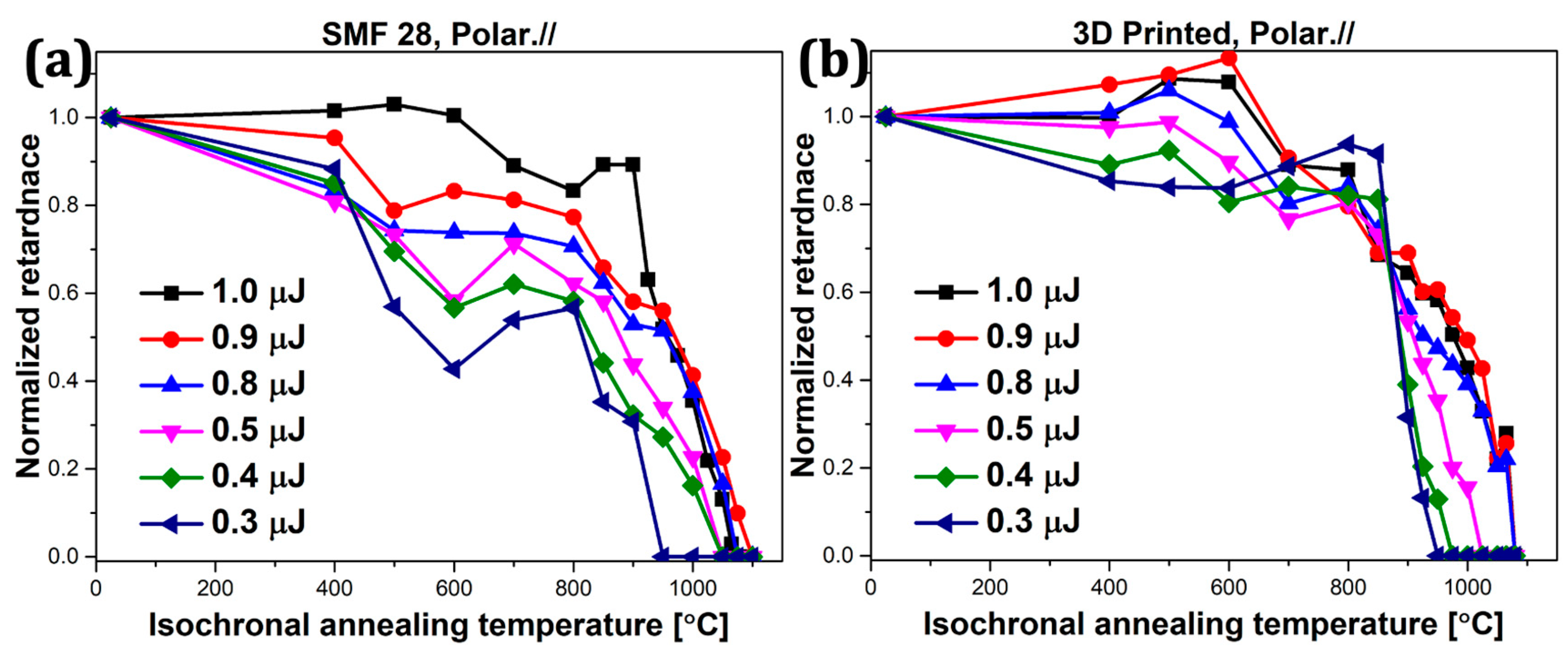
To further investigate the thermal stability of the written Type II modifications in 3D-printed fibers at different pulse energies, and once again to compare them with conventional CVD fibers, we annealed the irradiated samples isochronously from T = 400 °C to 1100 °C, with a constant time increment of 30 min at each temperature step. Figure 6 shows the evolution of normalized retardance (Rnorm) as a function of T for lines irradiated with different energy (E).
With different pulse energies, the two fibers exhibit similar trends during heat treatment. There are at least two distinct features in the retardance response, one at low temperature and one at high temperature. At low pulse energy (3D printed fibers Ep ≤ 0.7 µJ and SMF 28 fiber Ep ≤ 0.9 µJ) there is immediate retardance decay after the start of annealing. Typically, Rnorm decreases until T = 600 °C corresponding to a 20–60% decrease in magnitude. This effect is more pronounced for the lowest pulse energies. Next, R increases in the range of T = (600–800) °C and is also more pronounced in the low energy regime. In the literature the appearance of this unusual increase in retardance can be related to annealing out of the residual part of the Type I modifications [26] between the nanolayer, that is mostly attributed to densification and related stress field (and thus stress-induced birefringence). This leaves a higher birefringence or FBG reflectivity [11]. Type I modifications require a lower deposited energy than Type II during the irradiation. This means the contribution of Type I response on the measured retardance is likely higher during lower energy Type II modification. The more significant increase in retardance Rnorm of low energy Type II changes arise after the residual effects of Type I are “erased” or relaxed. This behavior has been observed across various conventional gratings written by UV (Type I, Type IA and Type II and Type IIA), with high temperature annealing, reflecting intrinsic amorphous material properties rather than laser writing [26].
As the annealing temperature increases beyond T = 800 °C, the Rnorm for all lines and at any pulse energy starts to decline, likely due to gradual stress relaxation that takes place below the glass transition temperature (~0.9 Tg for 30 min). Finally, the erasure of the porous nanolayers is observed over T = (950–1080) °C range as a function of the laser pulse energy [16]. Indeed, the higher the laser pulse energy, the higher the annealing temperature needed to fully erase Type II modifications. This can be explained by noting that as the energy increases, the non-linear writing light dosage increases. As the energy increases in the Type II range, the thermal stability of the modification is enhanced for both the processed 3D printed fiber and the SMF28 fiber. This is a typical case described in Reference [23] where there is a link between writing and erasure. When the pulse energy increases, the demarcation energy increases and more stable sites, or deeper traps, are accessed, and more stable species produced. The subsequent modifications become more stable. The process is reflective of the distribution of energies possible within amorphous materials; i.e., distribution of density states. More details will be discussed in the next section.
Given similar behaviors and stabilities between SMF-28 and the 3D silica printed fiber with respect to varying laser pulse energies, the thermal stability of Type II modifications and FBGs in all future 3D printed fibers can be similarly enhanced by optimizing the laser irradiation energy. The retardance values for the two types of fibers could not be reliably measured beyond the annealing temperature T = 1100 °C. We infer that mechanisms of Type II modifications erasure for both types of fiber are similar, and less affected by different fabrication techniques. This would imply that 3D-printed derived FBGs can also be used in high temperature environments. Furthermore, the 3D printed fiber appears to possess superior thermal stability in the low energy range. Various factors need consideration, however, including the higher GeO2 content in 3D printed fiber, though its impact in femtosecond laser processing is said to be insignificant [19]. The second potential factor contributing to better thermal stability could be very large non-orthogonal anisotropy of the fiber structure, both form, and stress based, the role of which is unclear between low and high energy exposures. Exposure can lead to anisotropic relaxation and potential effects on optical rotation depending on the orientation of the fiber itself. Future work will explore these details to establish whether this is an orientation characteristic or something caused by the manufacturing process.

4. Discussion

Recently, our group has demonstrated that the form birefringence related to the so-called nanogratings is quantitatively correlated to the porosity-filling factor of these nanostructures [27]. Control of the porosity was achieved by adjusting the laser pulse energy and the number of pulses/micron; i.e., the overlapping rate [28]. To further explore the reason why thermal stability is improved when irradiated with higher pulse energy in 3D printed silica fiber, the Rayleigh–Plesset (R-P) equation was used to simulate the erasure of pores in the nanostructure during the annealing process, and taking into account the same conditions for a direct comparison between experiment and theory. The equation describes the evolution of a spherical bubble inside an incompressible Newtonian fluid, and it can be expressed as follows:
Δ P ρ = R pore d 2 R pore dt 2 + 3 2 ( dR pore dt ) 2 + 4 η ( T ) ρ R pore dR pore dt + 2 S ρ R pore
Here, ΔP is the pressure difference (in Pa) between the inside of the nanopore (supposed spherical) and far away from it, ρ is the glass density (in kg/m−3), Rpore the radius (in m) of the spherical nanopore, t the time (in s), η(T) the viscosity (in Pas), and S is the surface energy (in J/m−2). The viscosity and its dependence with respect to temperature can be injected into the model by using a Vogel–Tammann–Fulcher (VTF) law in the form log(η) = A + B/(T−T0). Initial conditions are Rpore (at t = 0) = R0 and dRpore/dt (at t = 0) = 0.
The nanopore size diameter from the R-P equation needs to be converted into a normalized retardance (R) value and used to compare with the normalized R values obtained in the experiment. The Maxwell–Garnet equation [29] will be used first to calculate the average refractive index of the porous nanolayer (npl):
n pl = n G 2 n G 2 + ( 1 + 2 FF ) 3 ( n pore 2 n G 2 ) n G 2 + ( 1 FF ) 3 ( n pore 2 n G 2 )
nG is the fiber refractive index (taken as nG = 1.484, estimated from the chemical composition of the fiber), npore is the nanopore refractive index (taken equal to 1). Another important factor is the filling factor (FF) which is defined as the proportion of the nanopores’ volume taken in a unit volume of porous nanolayer (V), so it is obviously related to the number of nanopores (N) with an averaged nanopore radius (Rpore) and can be calculated using:
FF = N 4 π R pore 3 3 V
The birefringence B can be determined by the difference between the refractive indices of the ordinary axis (no) and the extraordinary axis (ne). The following equation illustrates the detail:
B = n o n e = [ 1 δ Λ ] n G 2 + δ Λ n pl 2 [ [ 1 δ Λ ] n G 2 + δ Λ n pl 2 ] 1
nG represents the refractive index between the porous nanolayers [28], Λ is the average spacing between nanolayers, δ is the porous nanolayer thickness, and (Λ–δ) is the interlayer thickness. Finally, with the birefringence B calculated, the retardance R can be worked out by the expression R = B × L as we defined above. More details about the simulation are provided in our recent work [16]. The conditions used in the simulation were set as: the surface energy (S) = 0.3 J/m−2; the viscosity η(T) fitted using a VTF (Vogel–Tamman–Fulcher) law for binary GeO2-SiO2 glass with (GeO2)~10 mol % [30].
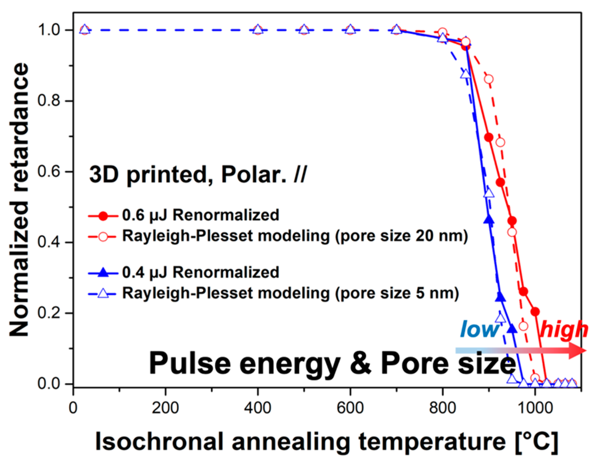
Measured annealing curves of the 3D silica printed fiber (pulse energies of 0.6 µJ and 0.4 µJ), and the predicted ones calculated based on the R-P, are shown in Figure 7. We suppose the total birefringence of the nanogratings is composed by the contributions additive and independent. Then, the measured data are normalized relative to the sharp retardance decrease at the highest annealing temperature values that we hypothesized here to be characteristic of the nanopore erasure. In this paper only the final erasure step of the measured retardance R(Δt,T) is investigated. Following the same experimental conditions as in the experiment, the R-P equation was used to simulate the nanopore erasure, and the evolution of the retardance was calculated based the nanopore diameter, the filling factor FF and using the form birefringence equations (Equations (2)–(4)) shown above.
As can be seen from experimental and simulation results in Figure 7, two pairs of curves are separated in the figure. The evolution in pulse energy corresponds to the increase in pore size, and each pair is consistent. Improved thermal stability can be observed as pulse energy or pore size increases. This work agrees with the previous simulation work carried out in glasses produced by mature fabrication technologies [16]. What this means is that similar to other glasses, the larger pore size induced by the higher laser pulse energy in the nanolayers can also play an extremely important role in the erasure of nanogratings and their associated birefringence in a high temperature regime for 3D printed silica glass.

5. Conclusions

The first study of the photosensitivity of the 3D printed silica fibers with fs-IR laser irradiation is reported. The results from the writing kinetics and isochronal annealing show that 3D printed fibers demonstrate similar, or slightly better, thermal stability in comparison with commercial single-mode fibers, which means that 3D printed fibers with complex configurations could be applied in high-temperature environments without the restriction of conventional fiber design and manufacturing.
Moreover, the thermal stability of these fs-IR laser inscribed structures in both 3D printed fiber and conventional fiber (Type II modifications) was studied and simulated with a Rayleigh–Plesset (R-P) model. Despite different fabrication routes, 3D printed fibers show comparable performance with SMF28 commercial single-mode fibers. Overall, 3D printed fibers are promising in FBG fabrication and high-temperature components for sensing applications. Regarding the laser-induced underlying porous nanostructure in silicate more generally, it can be treated as nanopores that slowly re-dissolve back into the glass with high temperature annealing. This dissolution is likely to be impacted by the surrounding environment that may account for some slight differences in response magnitude between the two fiber types.

Author Contributions

Conceptualization, Y.W., S.W., M.L., G.-D.P. and J.C.; methodology, Y.W., M.C. and M.L.; software, Y.W. and S.W.; validation, M.L., G.-D.P., J.C. and B.P.; formal analysis, Y.W. and S.W.; investigation, Y.W., S.W., M.C., B.S. and M.L.; resources, G.-D.P., J.C., B.P. and M.L.; data curation, Y.W., S.W. and B.S.; writing—original draft preparation, Y.W.; writing—review and editing, Y.W., S.W., M.C., J.C., B.P. and M.L.; visualization, M.L.; supervision, G.-D.P., J.C., M.L. and B.P.; project administration, M.L.; funding acquisition, M.L. All authors have read and agreed to the published version of the manuscript.

Funding

This research was funded by Agence Nationale pour la Recherche, FLAG/IR project, grant number ANR-18-CE08-0004-01 and CNRS Défi Instrumentation aux Limites, Ultrabragg project.

Institutional Review Board Statement

Not applicable.

Informed Consent Statement

Not applicable.

Data Availability Statement

The data presented in this study are available on request from the corresponding author.

Conflicts of Interest

The authors declare no conflict of interest.

References

  1. Ballato, J.; Dragic, P. Glass: The carrier of light-a brief history of optical fiber. Int. J. Appl. Glass Sci. 2016, 7, 413–422. [Google Scholar] [CrossRef]
  2. Geittner, P.; Küppers, D.; Lydtin, H. Low-loss optical fibers prepared by plasma-activated chemical vapor deposition (CVD). Appl. Phys. Lett. 1976, 28, 645–646. [Google Scholar] [CrossRef]
  3. Luo, Y.; Wen, J.; Zhang, J.; Canning, J.; Peng, G.-D. Bismuth and erbium codoped optical fiber with ultrabroadband luminescence across O-, E-, S-, C-, and L-bands. Opt. Lett. 2012, 37, 3447–3449. [Google Scholar] [CrossRef] [PubMed]
  4. Michie, A.; Canning, J.; Bassett, I.; Haywood, J.; Digweed, K.; Åslund, M.; Ashton, B.; Stevenson, M.; Digweed, J.; Lau, A.; et al. Spun elliptically birefringent photonic crystal fibre. Opt. Express 2007, 15, 1811–1816. [Google Scholar] [CrossRef] [PubMed]
  5. Andreone, A. Selected Topics in Photonic Crystals and Metamaterials; World Scientific: Singapore, 2011. [Google Scholar]
  6. Cook, K.; Leon-Saval, S.; Canning, J.; Reid, Z.; Hossain, M.A.; Peng, G.-D. Air-structured optical fibre drawn from a 3D-printed preform. In Proceedings of the 24th International Conference on Optical Fibre Sensors, Curitiba, Brazil, 28 September–2 October 2015; International Society for Optics and Photonics: Bellingham, WA, USA, 2015; Volume 9634, p. 96343E. [Google Scholar]
  7. Chu, Y.; Fu, X.; Luo, Y.; Canning, J.; Tian, Y.; Cook, K.; Zhang, J.; Peng, G.-D. Silica optical fiber drawn from 3D printed preforms. Opt. Lett. 2019, 44, 5358–5361. [Google Scholar] [CrossRef] [PubMed]
  8. Hill, K.; Malo, B.; Bilodeau, F.; Johnson, D. Photosensitivity in optical fibers. Annu. Rev. Mater. Sci. 1993, 23, 125–157. [Google Scholar]
  9. Bricchi, E.; Kazansky, P.G. Extraordinary stability of anisotropic femtosecond direct-written structures embedded in silica glass. Appl. Phys. Lett. 2006, 88, 111119. [Google Scholar] [CrossRef] [Green Version]
  10. Li, Y.; Yang, M.; Wang, D.; Lu, J.; Sun, T.; Grattan, K.T. Fiber Bragg gratings with enhanced thermal stability by residual stress relaxation. Opt. Express 2009, 17, 19785–19790. [Google Scholar] [CrossRef] [Green Version]
  11. Wei, S.-E.; Wang, Y.; Yao, H.; Cavillon, M.; Poumellec, B.; Peng, G.-D.; Lancry, M. Thermal Stability of Type II Modifications by IR Femtosecond Laser in Silica-based Glasses. Sensors (Basel) 2020, 20, 762. [Google Scholar] [CrossRef] [Green Version]
  12. Grobnic, D.; Hnatovsky, C.; Mihailov, S.J. Low loss Type II regenerative Bragg gratings made with ultrafast radiation. Opt. Express 2016, 24, 28704–28712. [Google Scholar] [CrossRef] [Green Version]
  13. Mihailov, S.J.; Grobnic, D.; Hnatovsky, C.; Walker, R.B.; Lu, P.; Coulas, D.; Ding, H. Extreme environment sensing using femtosecond laser-inscribed fiber Bragg gratings. Sensors 2017, 17, 2909. [Google Scholar] [CrossRef] [PubMed] [Green Version]
  14. Shimotsuma, Y.; Kazansky, P.G.; Qiu, J.; Hirao, K. Self-organized nanogratings in glass irradiated by ultrashort light pulses. Phys. Rev. Lett. 2003, 91, 247405. [Google Scholar] [CrossRef] [PubMed] [Green Version]
  15. Lancry, M.; Poumellec, B.; Canning, J.; Cook, K.; Poulin, J.C.; Brisset, F. Ultrafast nanoporous silica formation driven by femtosecond laser irradiation. Laser Photonics Rev. 2013, 7, 953–962. [Google Scholar] [CrossRef]
  16. Cavillon, M.; Wang, Y.; Poumellec, B.; Brisset, F.; Lancry, M. Erasure of nanopores in silicate glasses induced by femtosecond laser irradiation in the Type II regime. Appl. Phys. A 2020, 126, 1–9. [Google Scholar] [CrossRef]
  17. Luo, Y.; Canning, J.; Zhang, J.; Peng, G.-D. Toward optical fibre fabrication using 3D printing technology. Opt. Fiber Technol. 2020, 58, 102299. [Google Scholar] [CrossRef]
  18. Davidson, M. The First Order (Full Wave) Retardation Plate. 2019. Available online: https://www.olympus-lifescience.com/fr/microscope-resource/primer/techniques/polarized/firstorderplate/#:~:text=The%20first%20order%20retardation%20plate%20is%20designed%20to%20introduce%20a,polarized%20light%20at%20a%2045%2D (accessed on 9 January 2021).
  19. Fedotov, S.S.; Drevinskas, R.; Lotarev, S.V.; Lipatiev, A.S.; Beresna, M.; Cerkauskaite, A.; Sigaev, V.N.; Kazansky, P.G. Direct writing of birefringent elements by ultrafast laser nanostructuring in multicomponent glass. Appl. Phys. Lett. 2016, 108, 071905. [Google Scholar] [CrossRef] [Green Version]
  20. Bricchi, E.; Klappauf, B.G.; Kazansky, P.G. Form birefringence and negative index change created by femtosecond direct writing in transparent materials. Opt. Lett. 2004, 29, 119–121. [Google Scholar] [CrossRef]
  21. Kazansky, P.G.; Shimotsuma, Y.; Sakakura, M.; Beresna, M.; Gecevičius, M.; Svirko, Y.; Akturk, S.; Qiu, J.; Miura, K.; Hirao, K. Photosensitivity control of an isotropic medium through polarization of light pulses with tilted intensity front. Opt. Express 2011, 19, 20657–20664. [Google Scholar] [CrossRef]
  22. Patel, A.; Tikhonchuk, V.T.; Zhang, J.; Kazansky, P.G. Non-paraxial polarization spatio-temporal coupling in ultrafast laser material processing. Laser Photonics Rev. 2017, 11, 1600290. [Google Scholar] [CrossRef] [Green Version]
  23. Poumellec, B.; Lancry, M. Kinetics of thermally activated physical processes in disordered media. Fibers 2015, 3, 206–252. [Google Scholar] [CrossRef] [Green Version]
  24. Gecevičius, M. Polarization Sensitive Optical Elements by Ultrafast Laser Nanostructuring of Glass. Ph.D. Thesis, University of Southampton, Southampton, UK, 2015. [Google Scholar]
  25. Canning, J.; Hossain, M.A.; Han, C.; Chartier, L.; Cook, K.; Athanaze, T. Drawing optical fibers from three-dimensional printers. Opt. Lett. 2016, 41, 5551–5554. [Google Scholar] [CrossRef] [PubMed]
  26. Grobnic, D.; Smelser, C.W.; Mihailov, S.J.; Walker, R.B. Long-term thermal stability tests at 1000 °C of silica fibre Bragg gratings made with ultrafast laser radiation. Meas. Sci. Technol. 2006, 17, 1009. [Google Scholar] [CrossRef]
  27. Lancry, M.; Canning, J.; Cook, K.; Heili, M.; Neuville, D.; Poumellec, B. Nanoscale femtosecond laser milling and control of nanoporosity in the normal and anomalous regimes of GeO 2-SiO 2 glasses. Opt. Mater. Express 2016, 6, 321–330. [Google Scholar] [CrossRef]
  28. Desmarchelier, R.; Poumellec, B.; Brisset, F.; Mazerat, S.; Lancry, M. In the heart of femtosecond laser induced nanogratings: From porous nanoplanes to form birefringence. World J. Nano Sci. Eng. 2015, 5, 115. [Google Scholar] [CrossRef] [Green Version]
  29. Markel, V.A. Introduction to the Maxwell Garnett approximation: Tutorial. JOSA A 2016, 33, 1244–1256. [Google Scholar] [CrossRef] [Green Version]
  30. Birtch, E.M.; Shelby, J.E.; Whalen, J.M. Properties of binary GeO2–SiO2 glasses. Phys. Chem. Glas. Eur. J. Glass Sci. Technol. B 2006, 47, 182–185. [Google Scholar]
Figure 1. Overview of 3D printed fibers fabrication: (a) The preform is produced using additive manufacture and annealed to remove the binding agent. It is then (b) sintered on an optical fiber draw tower and drawn into (c) optical fiber.
Applsci 11 00600 g001
Figure 2. GeO2 concentration profile across the core for two fibers: 3D printed fiber (squares) and SMF28 fiber (dots). D is the distance relative to the fiber core center. Inset: scanning electron micrograph of the 3D printed fiber core cross-section.
Applsci 11 00600 g002
Figure 3. (a): Experimental laser writing design: irradiation of fs laser inside fiber core and cladding of an optical fiber using different pulse energies. (b) Retardance, R, as a function of pulse energy for 3D printed fiber (squares) and SMF28 fiber (circles). Experimental conditions are: λ = 1030 nm, rr = 100 kHz, v = 100 µm/s, NA = 0.6, t = 250 fs, laser polarization ⊥ and // to writing direction. (c) Optical microscope image of for 3D printed fiber using crossed polarizer and analyzer with the Yx configuration (⊥). (d) Optical microscope image of 3D printed fiber using crossed polarizer and analyzer and a full retardation waveplate inserted at 45° indicating the orientation of the slow axis.
Applsci 11 00600 g003
Figure 4. Scanning electron micrographs in the 3D printed fiber, both at the cladding (a) and the core (b) area, for orthogonal laser polarization direction with respect to the writing direction, which permits sideways visualization of the nanogratings. (c) Optical microscope image of the cross section of 3D printed fiber. Experimental conditions are: λ = 1030 nm, rr = 100 kHz, v = 100 µm/s, NA = 0.6, t = 250 fs, E = 0.7 µJ/pulse.
Applsci 11 00600 g004
Figure 5. Thermal stability with normalized retardance, Rnorm, as a function of annealing temperature, T, for drawn 3D printed fiber (in blue) and SMF 28 fiber (in red), for // configurations. The pulse energy is E = 1 μJ and the measurements were performed at room temperature after each annealing step (Δt = 30 min).
Applsci 11 00600 g005
Figure 6. Normalized retardance (Rnorm, relative to its initial value at room T) as a function of temperature for (a) SMF 28 fiber and (b) 3D printed fiber; different pulse energies were used. Experimental conditions are: λ = 1030 nm, rr = 100 kHz, v = 100 µm/s, 103 pulses/µm, NA = 0.6, pulse duration t = 250 fs, laser polarization // to writing direction (Yy). The measurements were performed at room temperature after each annealing step (Δt = 30 min) and the results are normalized by the initial value of the untreated sample R (t = 0, and T = 20 °C).
Applsci 11 00600 g006
Figure 7. Evolution of the normalized retardance during step isochronal annealing experiments for 3D printed silica fiber in various pulse energies (taken from Figure 2b and re-normalized relative to the sharply decreased retardance value) compared with the Rayleigh–Plesset (R-P) equation used to simulate the nanopores’ erasure.
Applsci 11 00600 g007
Publisher’s Note: MDPI stays neutral with regard to jurisdictional claims in published maps and institutional affiliations.

