Article

Nonlinear Dynamic Response of a Precast Concrete Building to Sudden Column Removal

1
Department of Engineering and Architecture, University of Parma, 43124 Parma, Italy
2
European Centre for Training and Research in Earthquake Engineering, 27100 Pavia, Italy
3
Department of Structures for Engineering and Architecture, University of Naples Federico II, 80138 Naples, Italy
*
Author to whom correspondence should be addressed.
Appl. Sci. 2021, 11(2), 599; https://doi.org/10.3390/app11020599
Submission received: 25 November 2020 / Revised: 31 December 2020 / Accepted: 6 January 2021 / Published: 9 January 2021
(This article belongs to the Special Issue Structural Reliability of RC Frame Buildings)

Abstract

:
Robustness of reinforced concrete (RC) structures is an ongoing challenging research topic in the engineering community. During an extreme event, the loss of vertical load-bearing elements can activate large-deformation resisting mechanisms such as membrane and catenary actions in beams and floor slabs of cast-in-situ RC buildings to resist gravity loads. However, few studies have been conducted for precast concrete (PC) buildings, especially focused on the capacity of such structures to withstand column loss scenarios, which mainly relies on connection strength. Additional resistance resource and alternate load paths could be reached via tying systems. In this paper, the progressive collapse resistance of a PC frame building is analyzed by means of nonlinear dynamic finite element analyses focusing on the fundamental roles played by beam-to-column connection strength and tying reinforcement. A simplified modelling approach is illustrated in order to investigate the response of such a structural typology to a number of sudden column-removal scenarios. The relative simplicity of the modelling technique is considered useful for engineering practice, providing new input for further research in this field.

1. Introduction

In the last decades, the engineering research community has focused on progressive collapse of reinforced concrete (RC) buildings, especially after the terroristic attack on the World Trade Center in 2001 [1]. Eurocode 1 [2] defines the structural robustness as the “ability of a structure to withstand events like fire, explosions, impact or the consequences of human error, without being damaged to an extent disproportionate to the original cause”. Such unforeseen events may cause loss of vertical load-bearing elements and the evaluation of structural robustness relies upon the capacity of the residual structure to redistribute gravity loads among the adjacent undamaged elements and to guarantee the development of alternate load paths.
In the context of cast-in-situ RC structures, several experimental tests were performed mainly to analyze beam [3,4,5,6,7,8,9,10], beam-slab [11,12,13,14,15] and flat-slab [16,17,18] sub-assemblies. Those results have shown that the main resisting mechanisms to column loss scenarios are the compressive arch and/or membrane action developing in beams and slabs under small-to-moderate displacements, as well as tensile catenary/membrane action under large displacements.
In the context of precast concrete (PC) structures, exhaustive indications for progressive collapse assessment are still lacking from experimental, numerical and normative points of view [19]. The crucial elements for the robustness assessment of PC structures are as follows: (i) the connection detailing, (ii) the role of joints, especially for existing structures, (iii) the diaphragm contribution and tying systems. In previous experimental tests on reduced-scale sub-assemblies, the effect of joint design was investigated [20,21,22] and improvements of joints were proposed to achieve higher progressive collapse performances of PC planar frames [23,24,25,26,27]. The influence of horizontal restraints was investigated by Wang et al. [28]. To the best knowledge of the authors, a single experimental program on existing planar PC frame is reported by Almusallam et al. [29]. Limited experimental tests on reduced-scale PC slab and beam-slab sub-assemblies are available in the literature [30,31,32,33]. Previous test results have shown that the resisting contribution of hollow-core slabs is not negligible if topping mesh reinforcement is provided [30].
Specific code prescriptions are still lacking for PC structures. Two fib guidelines on PC buildings subject to accidental actions are available. The first guideline is the fib Bulletin 63 [34], which provides main requirements for PC systems to resist accidental actions. Detailing requirements are reported in the fib Bulletin 43 [35]. Unfortunately, current codes are mainly single-hazard oriented, without reference to multi-hazard events and design [36]. Few researchers investigated novel connections and detailing in order to improve both seismic and progressive collapse performances [37,38]. In Europe, PC structures are mainly designed to resist seismic actions via dry connections composed by mechanical devices to connect beam and column precast members, typically with threaded dowels [39,40,41]. At the design stage, extreme actions able to cause the sudden loss of one or more vertical load-bearing elements are usually neglected, thus resulting in structural systems that are not necessarily capable of withstanding gravity-induced progressive collapse, nor of developing a rationally conceived alternate load path system to control or at least mitigate the vulnerability of such structures. The above brings into question the performance of these structural systems for low-probability/high-consequence events of this type—and other than earthquakes—and motivates the series of analyses presented in this study, which has a two-fold scope: (i) to develop easy-to-use yet reliable numerical modelling concepts applicable to the studied reinforced precast concrete frame system, and (ii) to assess its capacity, in performance-oriented fashion, against that of a counterpart monolithic RC frame system.
The primary aim of this study is to investigate the progressive collapse performance of precast RC buildings, considering the influence of connections and tying reinforcement in terms of both layout and capacity for different column-removal scenarios that can be referred to as the upper and lower bounds for progressive collapse resistance estimate. It is noteworthy that the proposed modelling approach relies upon well-known fiber modelling criteria [42,43], adding mechanics-based constitutive modelling rules to mimic the likely behavior and kinematics of connections and details typical of the PC structural system of interest.
The findings of this study are considered useful for practitioners due to the simplicity of the modelling approach adopted, which can match accuracy and suitability of results without excessively sophisticated finite element (FE) analyses. Modelling criteria for nonlinear dynamic simulation are combined with an ad-hoc set of damage/performance limit states that (i) can support the interpretation of analysis results at different code-compliant progressive collapse load levels, and (ii) can be of great help towards probabilistic fragility assessment of similar structural archetypes.

2. Case Study and Modelling Technique

In the following, geometric characteristics and assumptions related to the selected case study are reported, as well as the FE modelling and analysis technique.

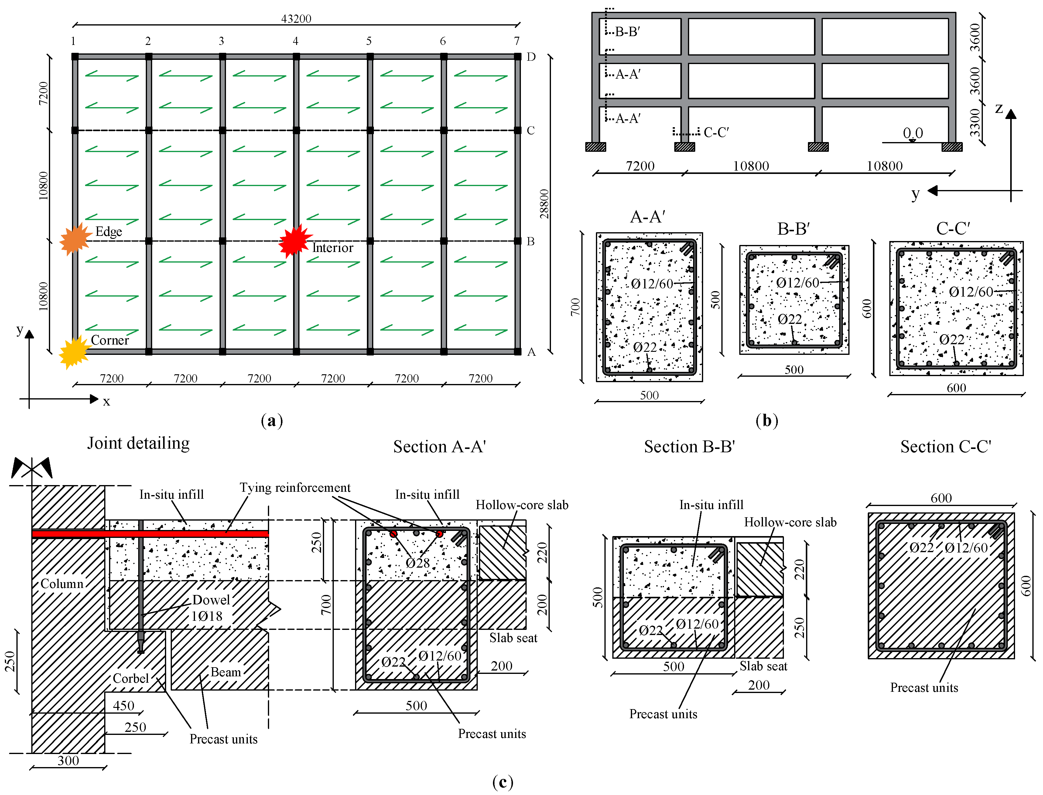
2.1. Description of the Case Study

The reference building is a three-story RC structure intended for commercial use. The structural layout is composed by primary and secondary beams as well as floor slabs. The precast units of the floor are oriented along the longest side of the frame, as reported in Figure 1a. The building dimensions in plan are equal to 43.2 and 28.8 m along the X and Y directions, respectively. The inter-story height is 3.3 m for the first floor and 3.6 m for the upper floors, as shown in Figure 1b. Different column loss scenarios at the ground floor are supposed to occur at interior (B4), edge (B1) and corner (A1) locations, as shown in Figure 1a.
In this study, two structural typologies are analyzed: moment resisting frame (MRF) and precast concrete frame (PCF) systems. Detailing of MRF and PCF systems is reported in Figure 1b,c. In the MRF system, beams and columns are monolithically connected to each other. Columns have 600 × 600 mm2 square cross section, whereas beams have 500 × 700 mm2 at the first and second floor levels. Beams with 500 × 500 mm2 square cross section are used at the roof level and along the X direction at each floor level. All beams and columns have Ø22 longitudinal bars and Ø12 stirrups with 60 mm spacing. In the PCF system, beams and columns have similar cross section compared to MRF system and are connected through threaded dowels, whereas joints are completed with in-situ infills, Figure 1c. Moreover, tying reinforcements are provided in the PCF system to meet the fib Bulletin 63 [34] requirements. Indeed, to improve the progressive performance of precast RC structures subject to progressive collapse scenarios, tying systems should be placed in the transverse, longitudinal and vertical directions to provide additional integrity, redundancy and alternate load paths [34].
Note that corbel and beam end recess detailing are assumed to be properly designed [35]. Referring to Figure 1c, two 28-mm diameter rebars are used as tying reinforcement, whereas a Ø18 threaded dowel is used to connect precast beam and column members. Holes are provided into the precast columns to allow the passage of tying reinforcement. Moreover, beam seats are provided to allow the positioning of hollow-core slab. Design gravity loads follow the Unified Facilities Criteria [44] combination, which is more conservative than that of Eurocode 0 [45] as follows:
Q b = 1.2 D L + 0.5 L L
where DL and LL are dead and live loads, respectively. Dead loads consider the self-weight of resisting-members and 22-mm-thick hollow-core slab (3.2 kN/m2), partition walls and equipment (3.2 kN/m2) and exterior panels (3.5 kN/m2), whereas live loads are assumed equal to 4 kN/m2. Table 1 outlines the line loads at different floor levels and column removal locations.
The following properties of concrete and reinforcing steel were assumed: compressive cylinder strength of concrete fc = 50 MPa and elastic modulus Ec = 32.5 GPa; steel for longitudinal and transverse reinforcement as well as for threaded dowels with yield strength fy = 500 MPa and elastic modulus Es = 200 GPa; steel strain at fracture εsu = 20% and strain hardening ratio k = 0.01.

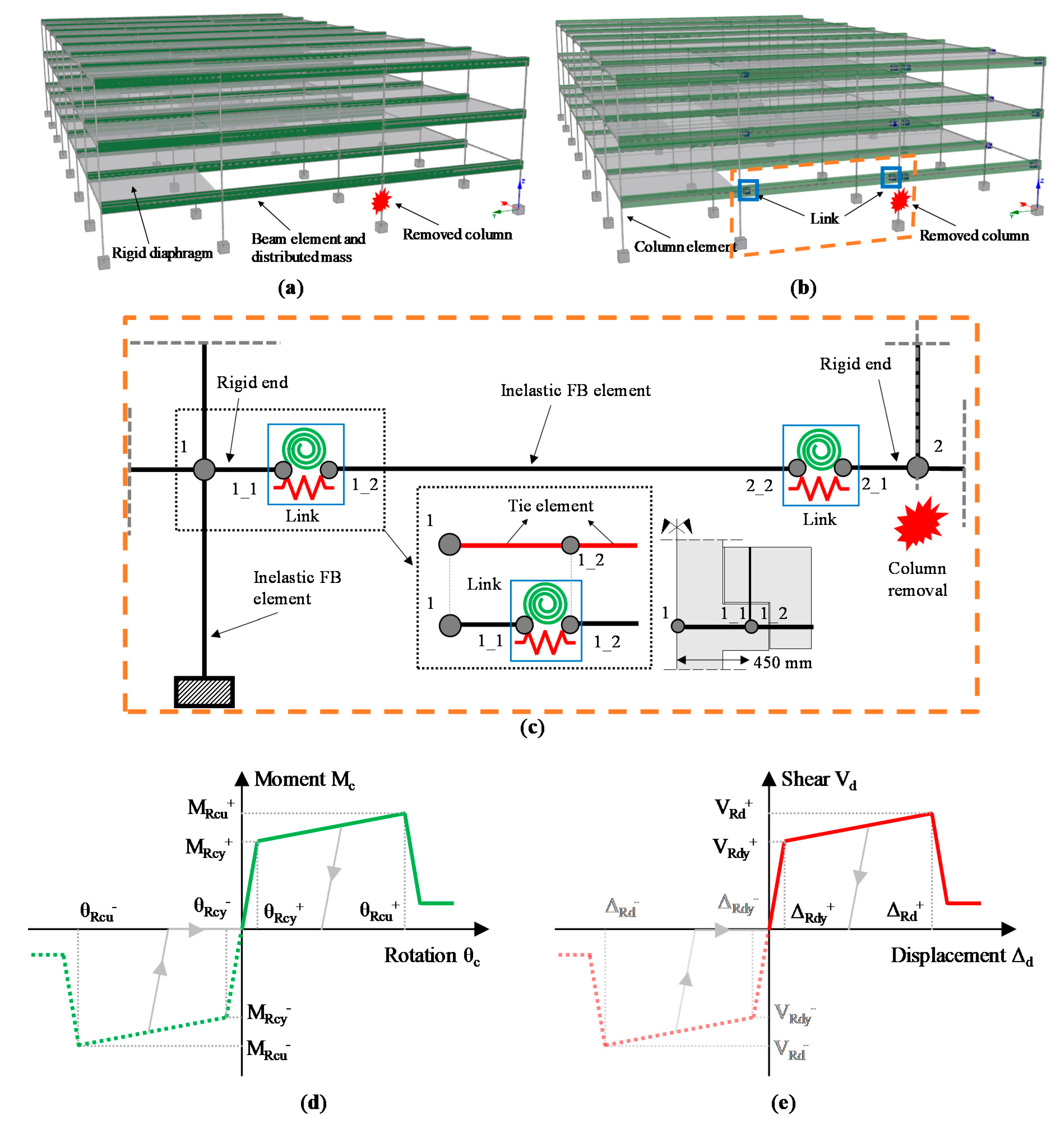
2.2. FE Modelling and Analysis Technique

Nonlinear time history analyses (NLTHA) were carried out using Seismostruct FE code [46] to investigate threat-independent, sudden column-loss scenarios of the selected case study. The force-based (FB) fiber modelling approach [47] was used to predict the nonlinear response of the case-study building. Beam-column fiber elements with distributed plasticity approach were used to model the frame members. Mechanical and geometrical nonlinearities were included in the model to account for the actual structural behavior under large displacements and rotations. Each member nearby the column loss location was modelled using two FB elements, each of them with 5 integration points and 300 fibers, which were considered enough to describe the deformed shape during progressive collapse analysis. Sectional stresses and strains were computed at individual fibers through direct integration of the uniaxial material response. Reinforcing steel behavior was modelled though a bilinear stress-strain relation, whereas the Mander curve [48] was used for concrete, which is able to account for confinement effect provided by stirrups. Strain rate effects [49] were conservatively neglected in this study.
In Figure 2a,b, FE models for MRF and PCF systems under edge column loss scenario are shown. Gravity loads were applied to the structure through masses per unit length over beams. The column base nodes were fixed to the ground. The resisting contribution of the floor diaphragms was conservatively neglected and only their self-weight was considered. Moreover, the diaphragm was removed at the column loss level, while keeping an in-plane rigid floor at the 2nd and 3rd floor levels. Column loss scenarios were simulated by deactivating designated elements after a time equal to 0.01 s, whereas the total time of NLTHA was set to 3 s and the convergence tolerances were based on displacement/rotation criteria. A tangent stiffness-proportional Rayleigh damping and the Newton–Raphson algorithm were used.
In the case of PCF system, the shear and rotational behaviors of the connections between precast beams and columns were modelled in Seismostruct using “link” elements between two overlapping nodes, as shown in Figure 2c. Furthermore, referring to Figure 2d,e:
  • An isotropic hardening quadrilinear asymmetric relation was assigned to the connection moment–rotation behavior;
  • An isotropic hardening quadrilinear symmetric relation was assigned to the connection shear-displacement behavior.
It is noted that link deformations are related to relative displacement and rotation between nodes 1_1 and 1_2 (see Figure 2c). Link degrees of freedom (DOFs) are uncoupled, so it is not possible to account for the interaction between shear and moment. The remaining DOFs were considered fixed. For the sake of simplicity, links were inserted in the only bays directly affected by column removal. The beam-to-column eccentricity was modelled by adding a rigid element between the precast column and beam nodes, see Figure 2c, which corresponds to 450 mm (refer also to Figure 1c).
The following two variants of PCF system were considered:
  • PC1: in addition to the connections modelled as springs, the tying reinforcement was considered by adding truss elements (see Figure 2c), which simulates the continuity provided by ties along the beam members, as provided in the fib Bulletin 63 [34];
  • PC2: the only connections modelled as links are used, neglecting the tying rebars.
NLTHA was carried out according to the following steps:
  • Gravity loads were applied to the structure through distributed masses along beam and column members;
  • The designated column was dynamically removed until the structural equilibrium was achieved or not.
Details concerning rotational and shear behaviors of connections are reported in the following sections.

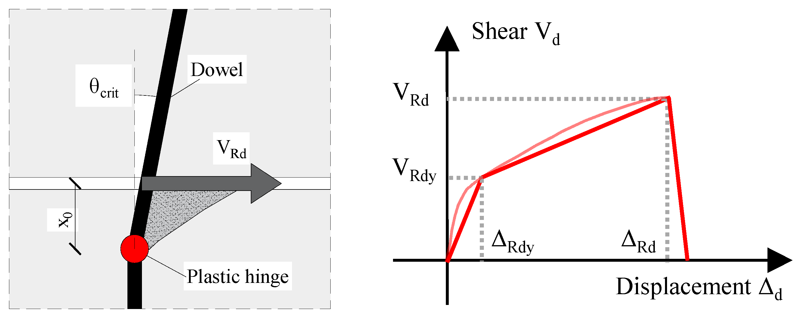
2.2.1. Shear-Displacement Relationship for Translational Spring

The shear-displacement behavior of the connection was modelled by assuming the relationship reported in the fib Bulletin 43 [35] for one-sided dowel, see Figure 3. Although the actual relation is expressed by a power function, a symmetric skeleton curve was used in the simulations. The strength loss of the dowel was accounted for by calculating its ultimate resistance VRd and the corresponding displacement ΔRd. The residual shear resistance was assumed to be negligible.
The shear resistance VRd of the dowel is expressed by [35]:
V R d = α ϕ d 2 f c f y d
where α is set equal to 1, Ød is the diameter of the dowel, fc is the concrete compression strength, and fyd is the steel yield strength of the dowel. Referring to Figure 3, VRdy is assumed to be 0.5VRd, whereas the displacements ΔRdy and ΔRd are calculated using:
Δ R d y = 2 V R d β E E c
Δ R d = θ c r i t x 0
where the coefficient βE is related to concrete and steel moduli Ec and Es and the inertia moment of the bar IS through:
β E = ( E c / ( 8 E s I s ) 0.25 )
In the end, the critical rotation of the dowel θcrit and the distance of the plastic hinge from the joint face x0 was calculated as follows (see Figure 3):
θ c r i t = k r ε s y ϕ d
x 0 = V R d 3 α 2 f c ϕ d
where kr is 1.75 m [35] and εsy is the steel yield strain.

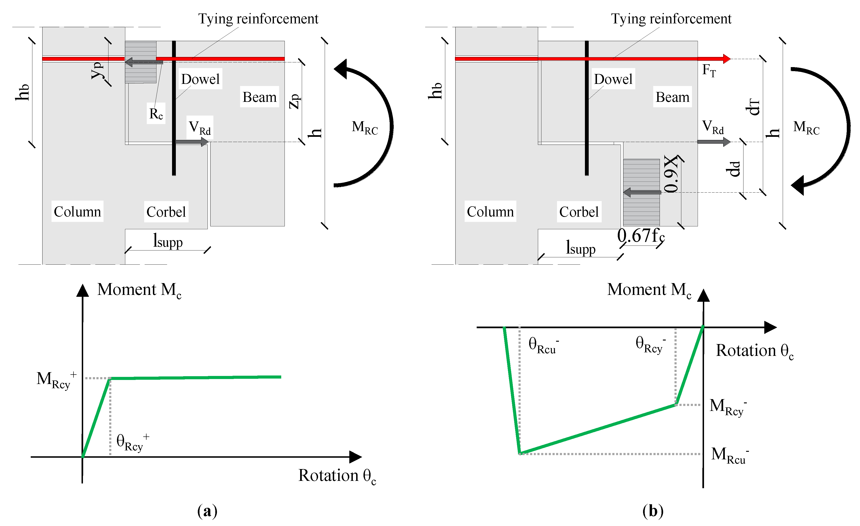
2.2.2. Moment–Rotation Relationship for Rotational Spring

To consider the rotational behavior of structural connections between beam and adjacent column members, the moment–rotation relationships for both negative and positive branches are required. The positive branch was calculated through the formulation by El Debs et al. [50], see Figure 4a. The rotational equilibrium of the connection relies on the stress block of concrete in compression and on dowel strength. The connection skeleton curve is represented by the yield moments and rotations, and no ultimate resistance calculation is provided. For this reason, the residual strength of the connection was kept constant and equal to the yield value until large connection rotations were achieved. The negative moment branch was calculated according to Elliott et al. [51,52], see Figure 4b, which is able to consider the contributions of dowel and/or continuous reinforcement. As reported in Figure 4b, the rotational equilibrium of the connection relies on the stress block of concrete in compression and on dowel and/or continuous reinforcement forces. The connection skeleton curve is represented by the yield and ultimate moments and rotations. The residual strength of the connection is assumed to be negligible after the achievement of the ultimate rotation.
Regarding the positive moment–rotation relationship (Figure 4a) the connection yield moment MRcy considering only the dowel strength was defined as follows:
M R c y = V R d z p
where zp is equal to (hb – 0.5yp). The height of the compression zone yp was calculated through the following equation:
y p = V R d f c b
where b is the beam width and fc is the concrete compressive strength. The rotational stiffness kp of the connection was calculated through moment equilibrium as follows:
k p = λ ( h b 0.5 y p ) 2
where λ is the stiffness associated with the shear deformation of the dowel:
λ = V R d 0.1 ϕ d
The rotation θRcy was then calculated by the moment MRcy to stiffness kp ratio.
The negative moment–rotation diagram (Figure 4b) was constructed by assuming the connection yield moment MRcy to be associated with yielded tying reinforcement AsT as follows:
M R c y = f y A s T ( d T 0.45 X )
The neutral axis depth X was defined through the following equation:
X = f y A s T 0.67 f c 0.9 b = F T 0.67 f c 0.9 b
where b is the beam width and fc is the concrete compressive strength. The term fy·AsT can be replaced by the dowel strength VRd if no tying reinforcements are considered [52]. The rotation at yield of the connection θRdy was calculated by summing three contributions:
  • The joint opening at the interface due to yield elongation of continuous reinforcing bars (or the achievement of the shear force of the dowel):
    θ R c y 1 = f y l e E s d T
    θ R c y 1 = V R d λ d d
  • The beam end rotation related to its curvature in the vicinity of the joint:
    θ R c y 2 = M R c y l p E c I b e a m
    where le is assumed equal to the column width, the length lp is equal to the sum of the corbel length lsupp and the total beam height h [52] (refer to Figure 4b) and Ibeam is the second moment of inertia of beams.
  • The column rotation on top and bottom of the joint zone:
    θ R c y 3 = M R c y h c o l E c I c o l
    where hcol is equal to the column height and Icol is the second moment of inertia of columns [52]. The last two contributions were assumed to be constant [52]. Considering the steel strain hardening ratio k and fracture strain εsu, the connection ultimate moment MRcu and rotation θRcu was easily calculated. Table 2 provides a summary of the calculation related to joint detail in Figure 1c with dT = 650 mm.

3. Performance Limit States Related to Column Loss Scenarios

The following performance limit states (PLS) were assumed related to PCF system:
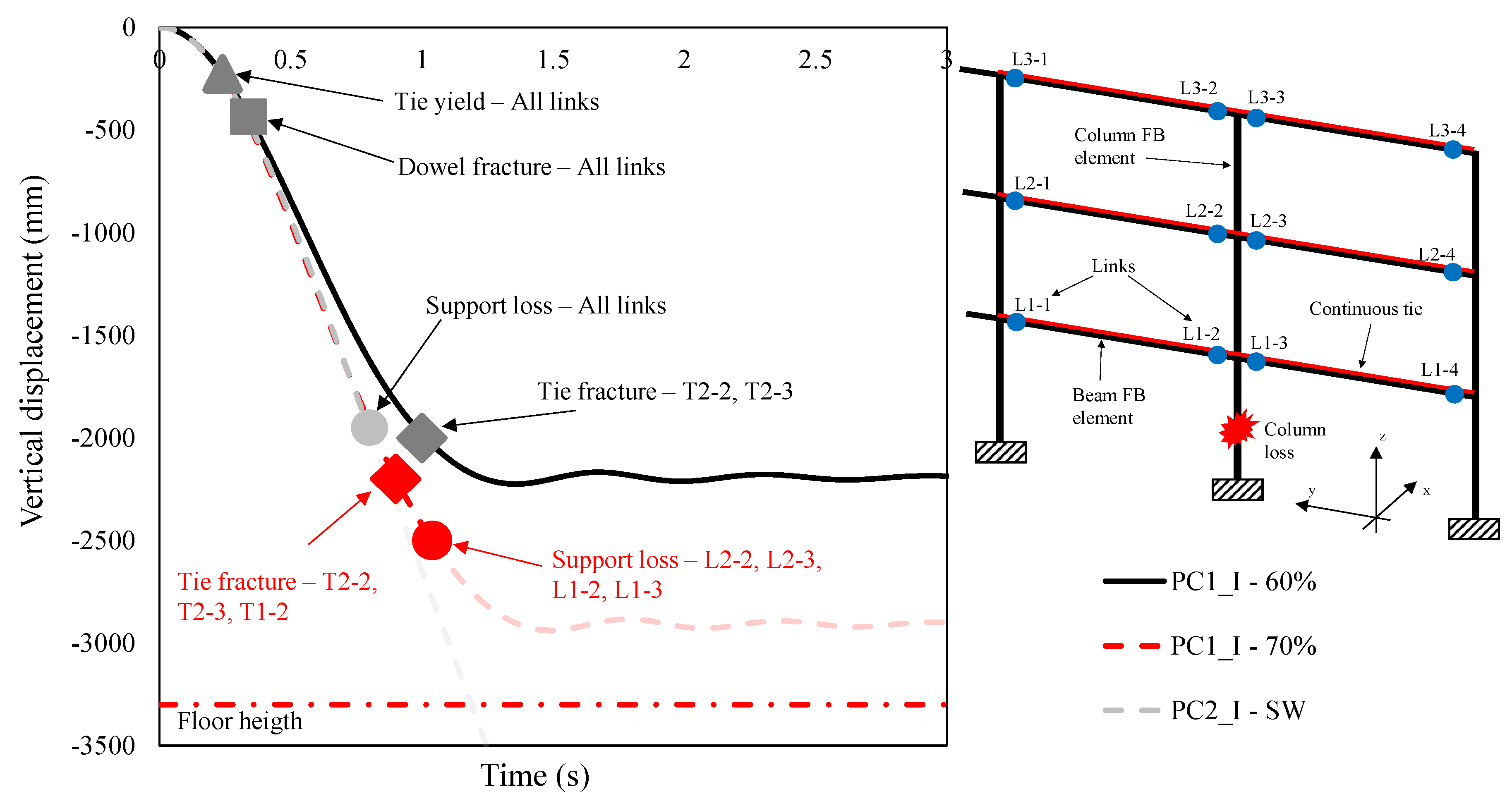
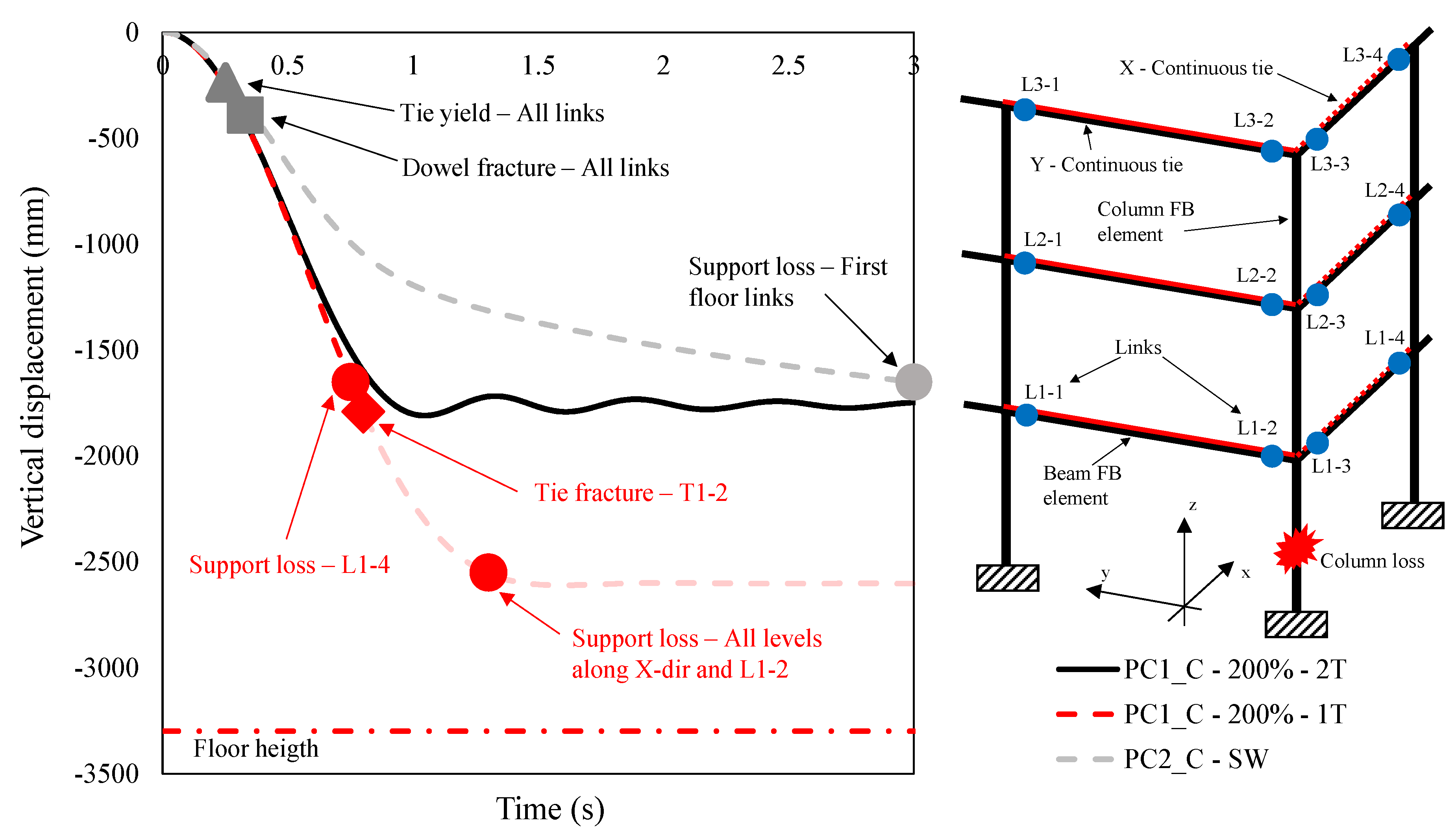
  • PLS1: tie or connection yielding. At this stage, the connections start to resist to applied loads in the inelastic range;
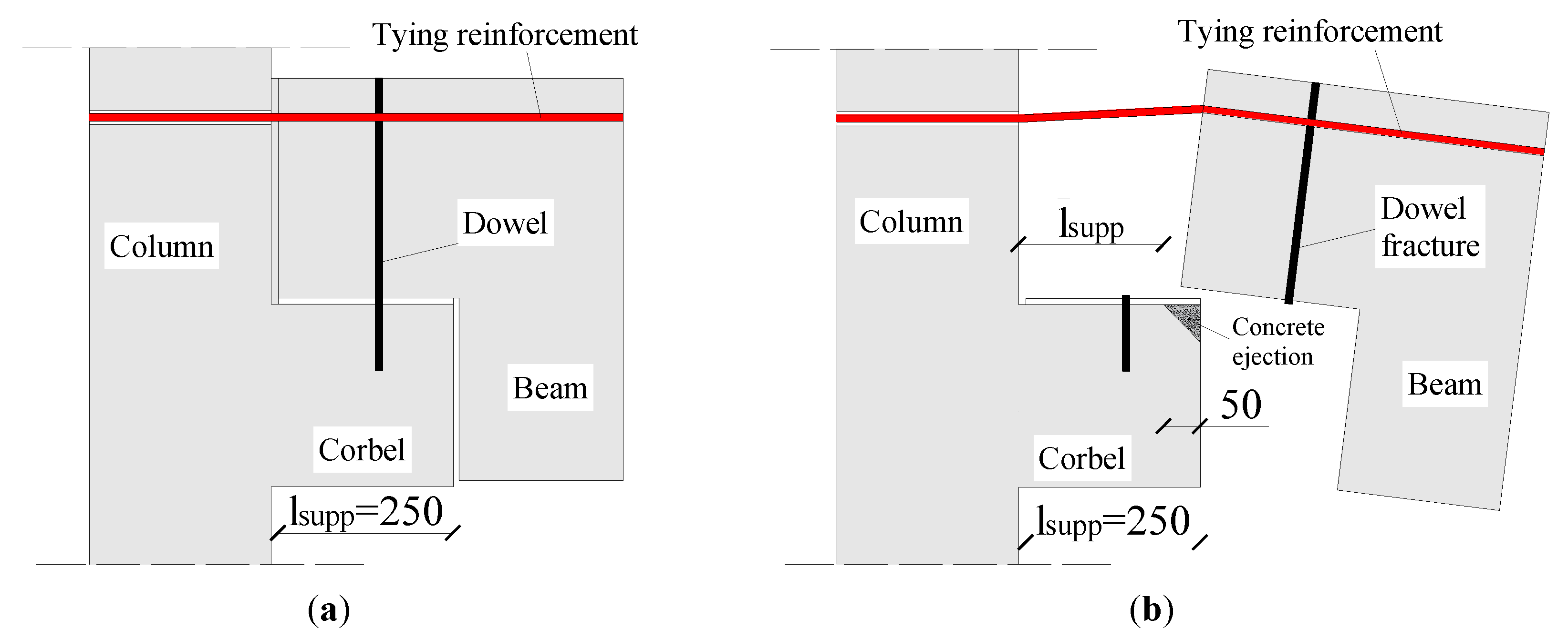
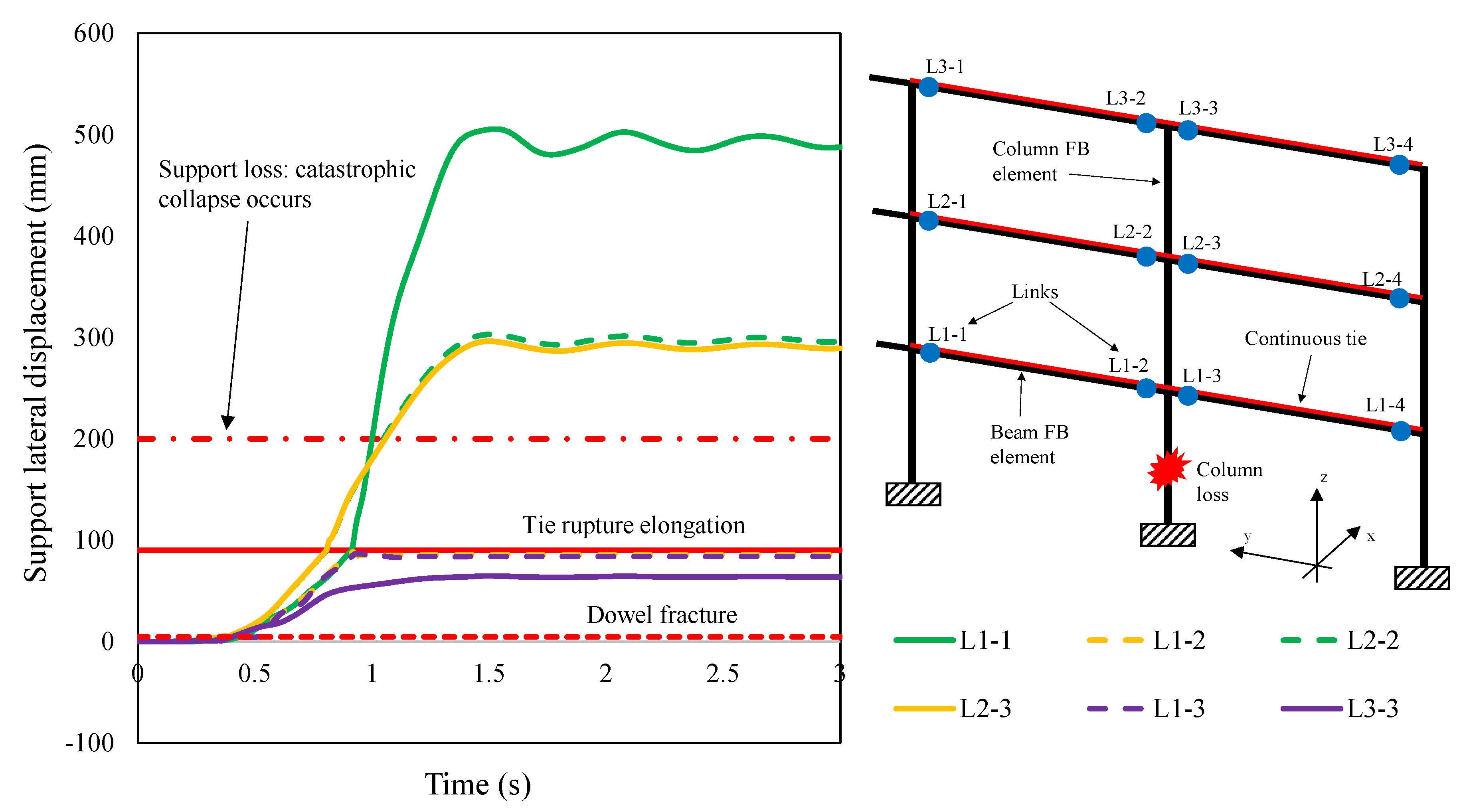
  • PLS2: dowel fracture. At this stage, the dowel shear strength is lost, and the resistance to applied loads relies on continuous reinforcements;
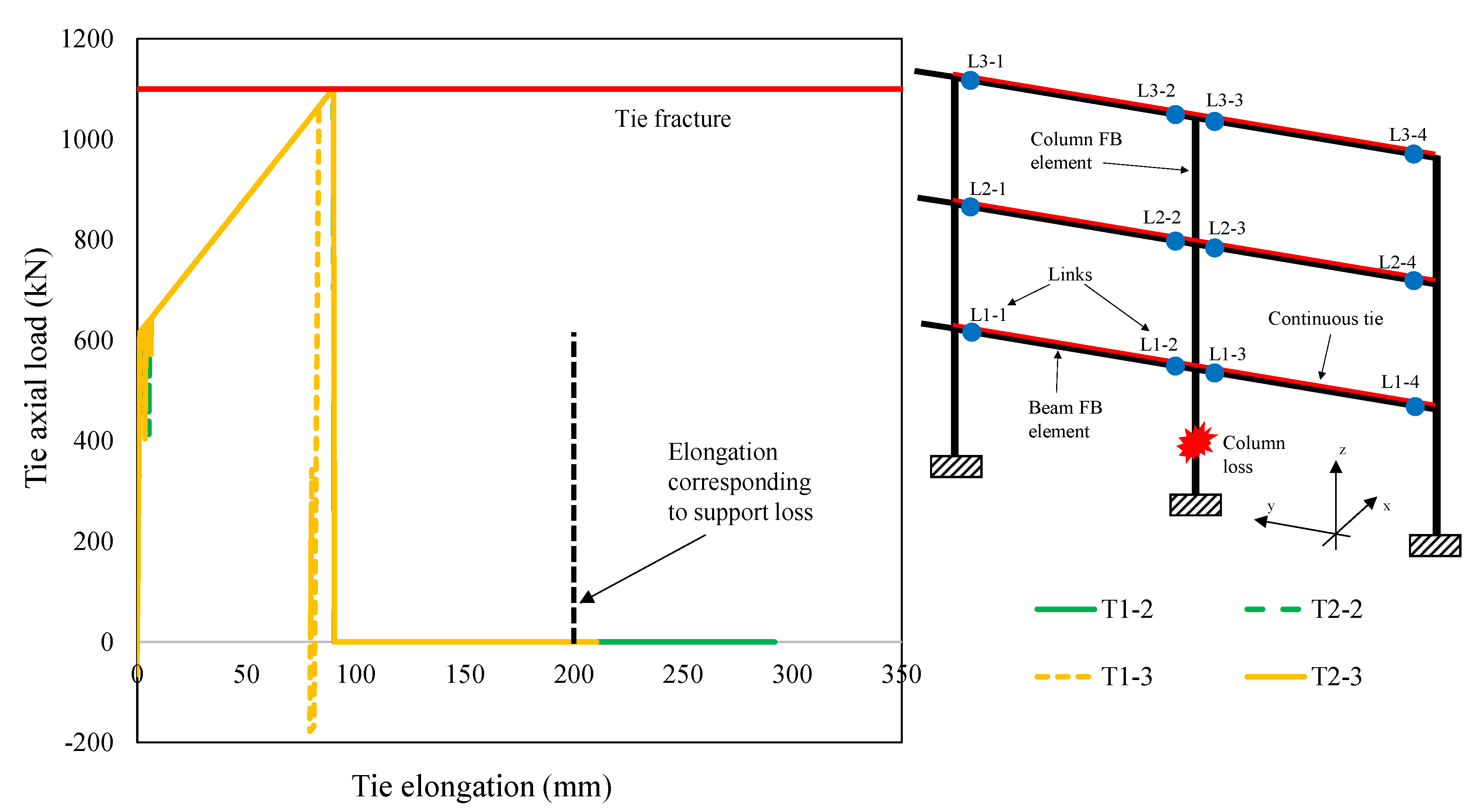
  • PLS3: tie or connection fracture. At this stage, the fracture of connection subject to negative moment or the tie fracture elongation is achieved;
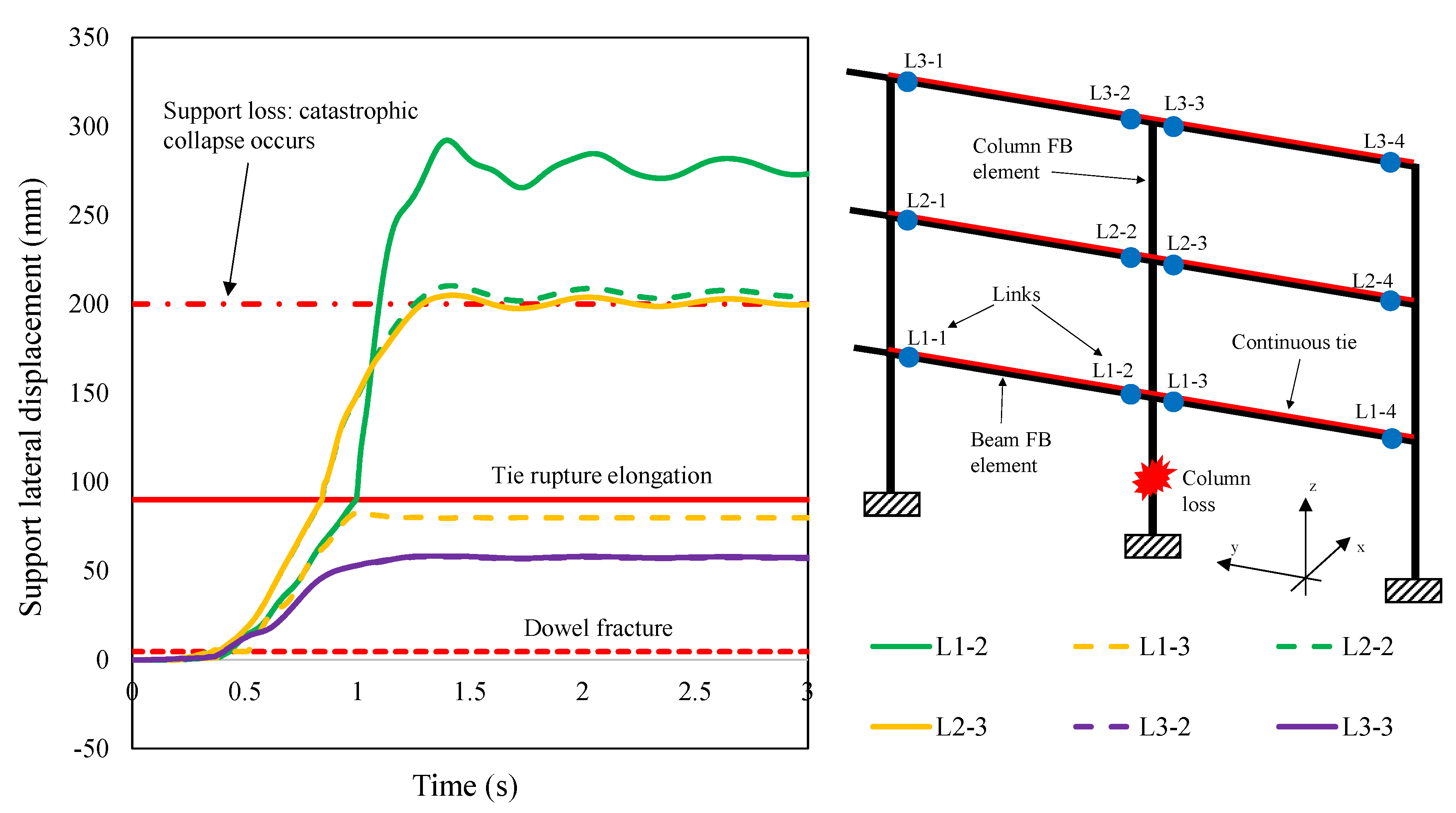
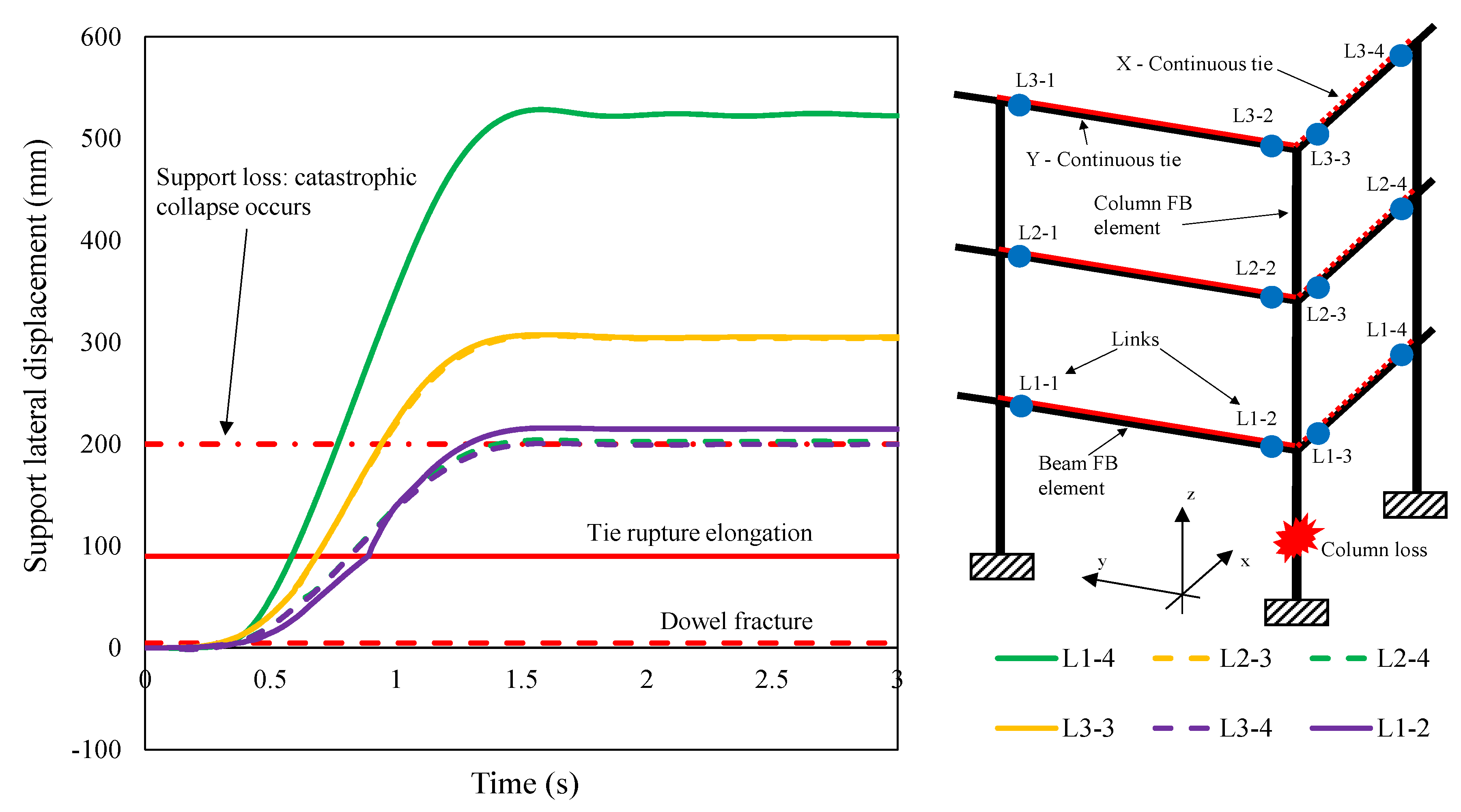
  • PLS4: loss of support. At this stage, precast beams experience a lateral displacement which is larger than a threshold value corresponding to a prescribed limit of support width.
It is worth to note that, although tie or connection fracture could be achieved in some specific positions, the structure could be able to sustain vertical loads if it is verified that the column support is not lost in all joints nearby the column loss location. For this reason, the PLS corresponding to the loss of support is considered the main indicator of catastrophic failure associated with a specific column-loss scenario in the case of PC structures. Referring to Figure 5, the threshold width associated with the support loss is related to the width of the column corbel (lsupp = 250 mm) reduced by a length equal to 50 mm that represents the damage effect in corbel corner. Hence, the support width limit was taken equal to 200 mm. This concept will be illustrated in the next section to analyze NLTHA results.
Referring to MRF system, the following PLSs were assumed:
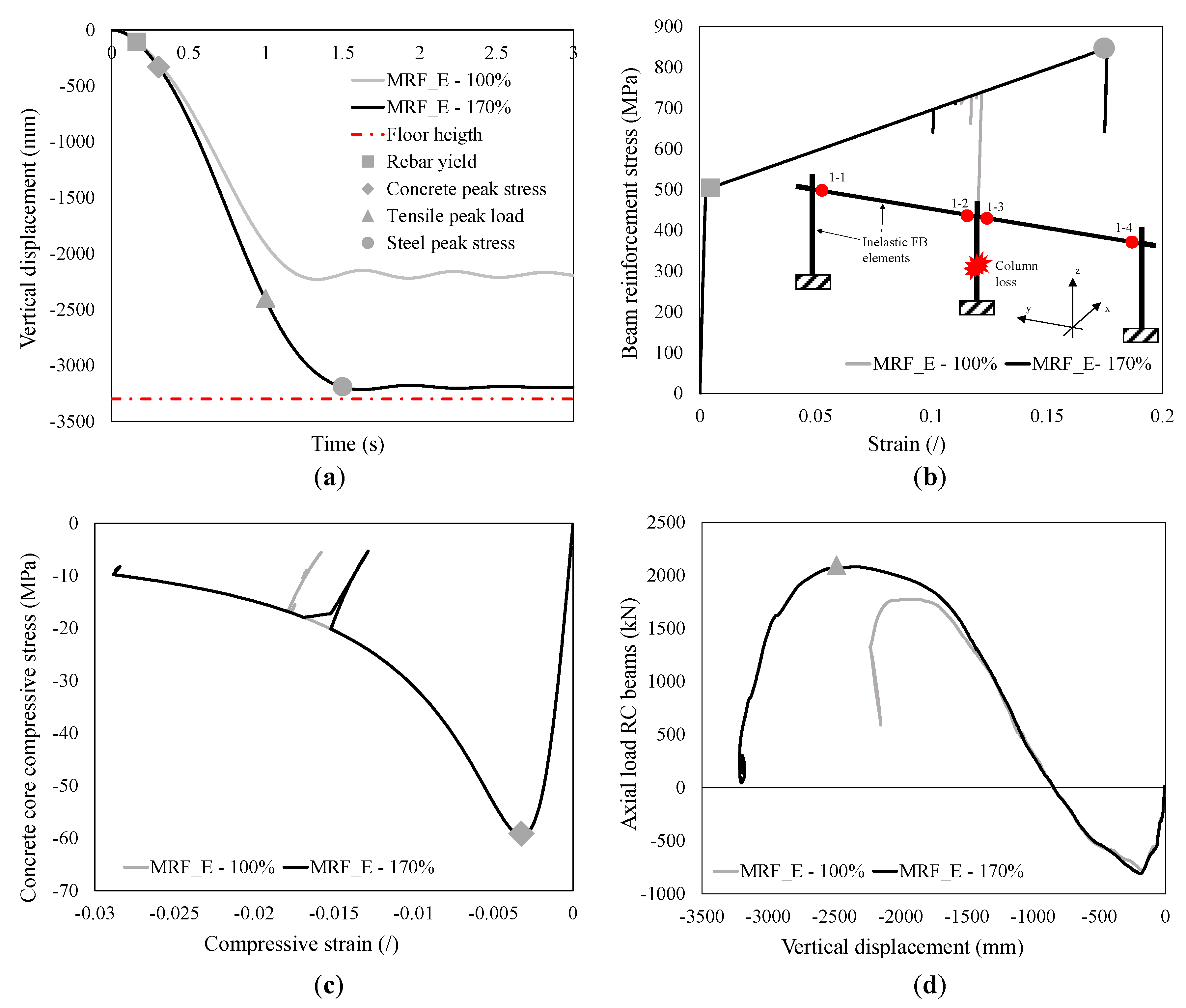
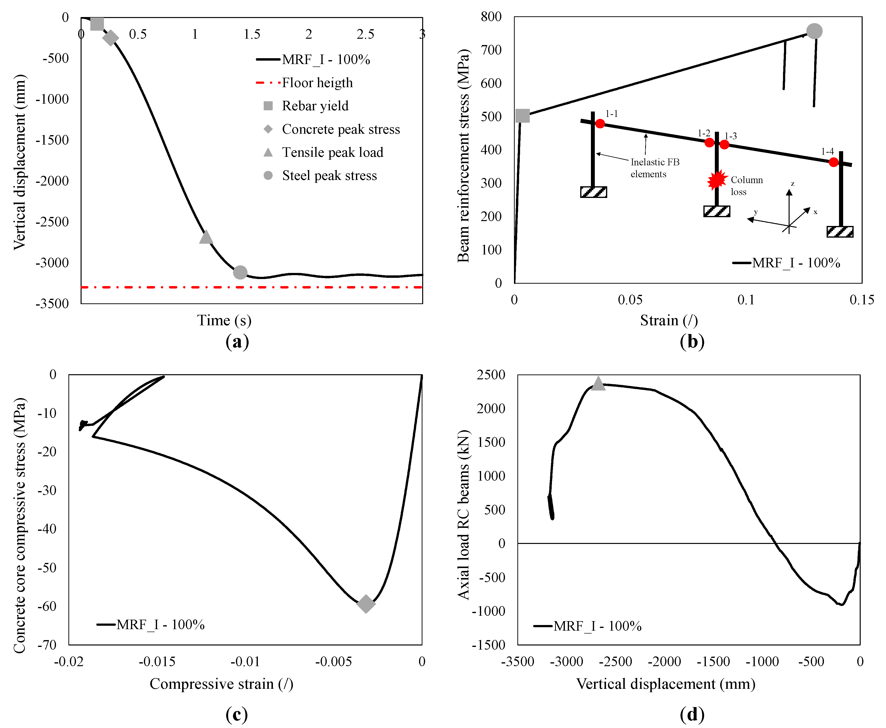
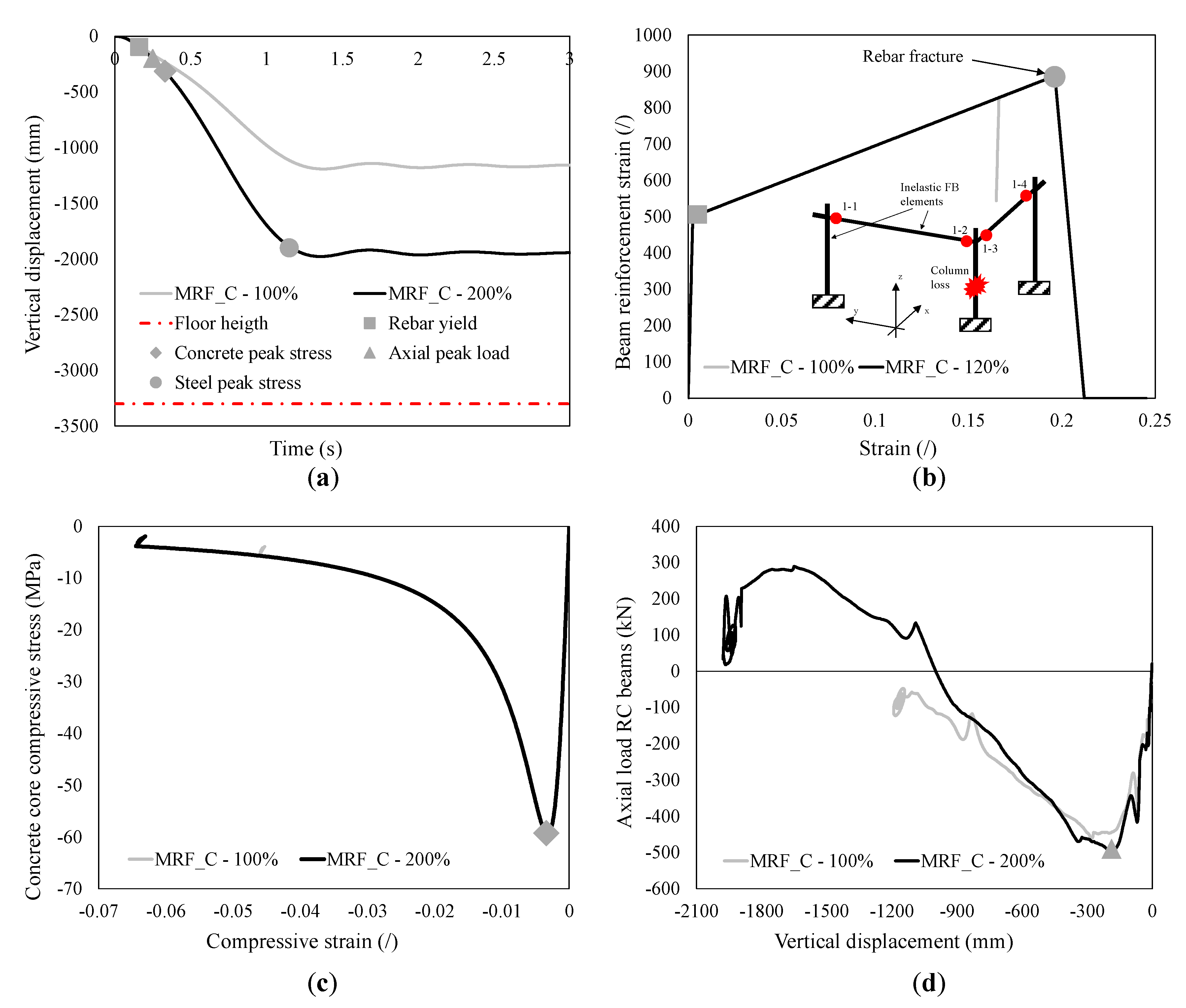
  • Achievement of longitudinal rebar yield strain. At this stage, structural members start to resist to applied loads in the inelastic range;
  • Achievement of concrete compressive peak stress;
  • Achievement of maximum axial load acting on beams above the removed column. This indicator is significant to assess the onset catenary action resisting mechanism;
  • Achievement of maximum tensile longitudinal rebar elongation. At this stage, the tensile rebars achieve maximum strain, which could correspond to the fracture strain.
Moreover, column and beam shear demands and capacities were also monitored during progressive collapse phenomenon to check brittle failure modes. Exceedance of EC8-conforming shear requirements [53] was notified whether demand exceeded capacity: in that case, shear strength was reduced by 50%.

4. Results and Discussion

In this section, the findings of this study are reported and discussed for each column removal scenario for MR and PC frame systems.

4.1. Edge Column Removal Scenario

4.1.1. Moment Resisting Frame System (MRF_E)

The moment resisting frame system subject to edge column removal scenario is investigated herein. Figure 6a shows the structural response results in terms of vertical displacement recorded at the location of the removed column and failure propagation occurring at the 1st floor level during progressive collapse phenomenon. Such responses are reported for the design load corresponding to accidental combination (100%·Qb,e in Table 1 for edge location) and increased load (170%·Qb,e). This procedure was adopted to establish the effective structural capacity of the selected MRF system subject to edge column loss compared to the gravity load demand. For the sake of simplicity, the sequence of failure events under increased load case is described. It is worth to note that the structure was able to sustain the increased gravity loads due to no rebar fracture occurrence and limitation of vertical displacement dictated by the 1st floor height equal to 3.3 m. Thus, the collapse load was not reached. At early stage, the first failure event was associated with the almost contemporary yield of tensile longitudinal rebars in correspondence of removed column (1-2 and 1-3 locations) and adjacent columns (1-1 and 1-4 locations) at 0.16 s (Figure 6b). This event was followed by the achievement of the concrete core peak compressive stress at adjacent columns (1-1 and 1-4 locations) at 0.30 s (Figure 6c).
In Figure 6d, the axial load in beams above the removed column are reported. At early stages, the compressive arch action was activated due to lateral frame stiffness. At a vertical displacement level of about 820 mm, the transition from compressive to catenary action occurred. A peak tensile load of 2000 kN was recorded until the equilibrium state was achieved. It is noted that similar delayed events occurred at the different floor levels. No brittle shear failures were detected.

4.1.2. Precast Frame System (PCF_E)

The precast frame system subject to edge column removal scenario is investigated herein. Figure 7 shows the structural response results in terms of vertical displacement recorded at the location of the removed column and main failure events occurring at the 1st ground level during progressive collapse phenomenon. As mentioned before, in addition to springs to simulate connection behavior, the PC1 model considers the presence of a tying system consisting of two 28-mm diameter rebars (indicated with red lines in the schematic view shown in Figure 7). This assumption meets the fib Bulletin 63 requirements [34]. Conversely, the PC2 model considers only springs to simulate connection behavior with no tying system. It is noted that, in Figure 7, the link and tie locations are identified with label L.
It is evident from Figure 7 that the PC1 system was not able to sustain the load magnitude corresponding to accidental combination (100%·Qb,e in Table 1). This is attributed to support losses which are experienced by precast beams at this load level. For this reason, it is interesting to find the threshold load level at which column loss does not occur. Under a load magnitude equal to 80% of the design accidental load Qb,e, the PC1 frame system did not show any support loss (i.e., PLS4 was not reached). Conversely, when the load magnitude was increased to 90% of Qb,e, the loss of column support occurred at the first floor level.
In addition to PC1 model, the PC2 model was investigated. In this case, the tying system was not included, so the frame resistance relied only on connection strength. It can be observed how such system was not able to sustain even the self-weight (reported with the label SW in Figure 7) of structural members and hollow-core slab. All supports were lost and the structure was unable to redistribute the applied loads. The analysis of this system is considered of a great importance, since it highlights the need to improve the structural robustness by adding tying systems.
In detail, the following main failure events corresponding to Figure 7 were detected based on the link (or ties) positions for PC1 model with support loss detection:
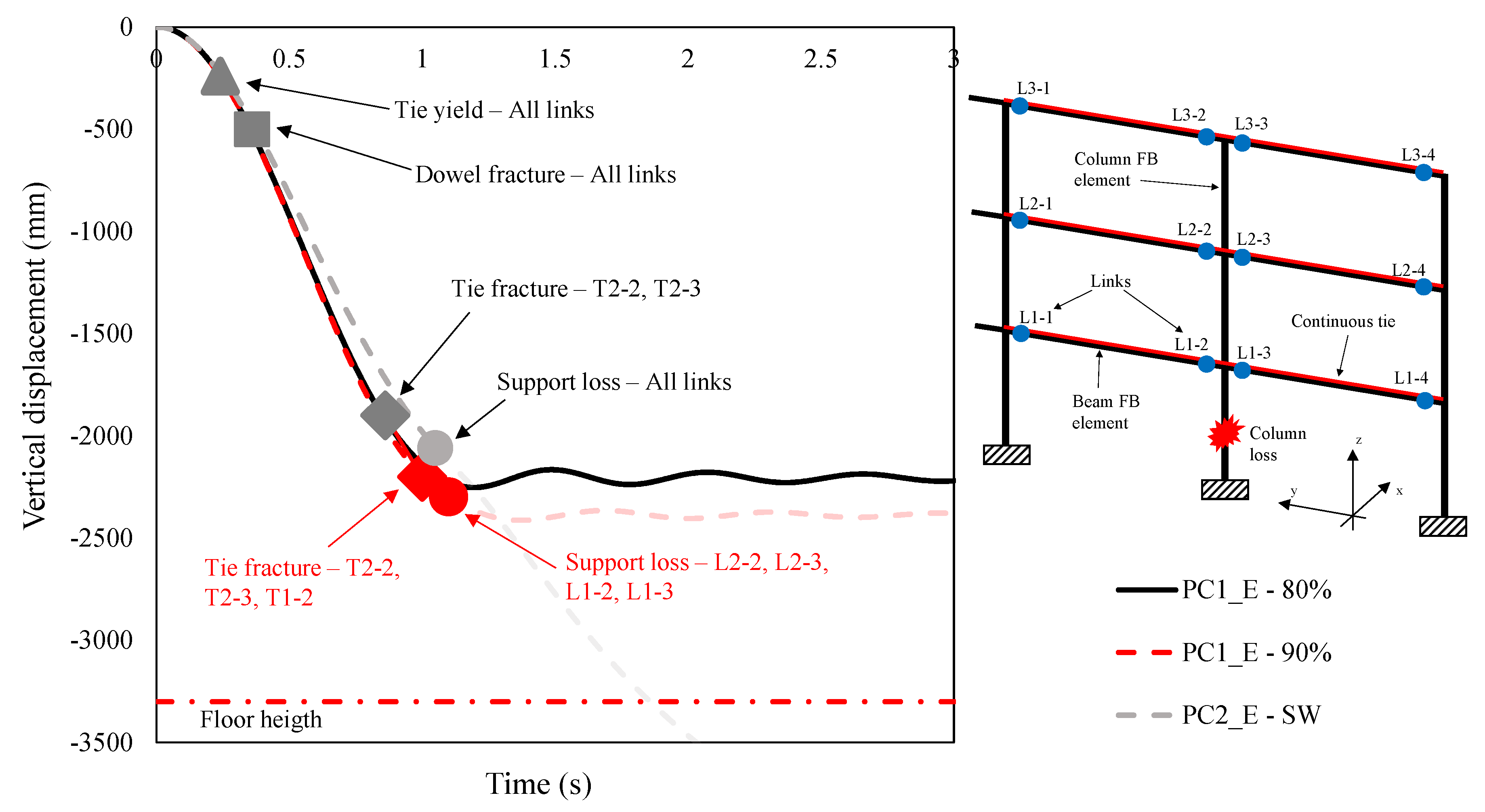
  • PLS1 was reached because of the yielding of all ties and all negative moment spring at each floor level;
  • PLS2 was reached because of fracture of all dowels at each floor level. This indicates that the structural response relies on the flexural contributions of rotational springs and tying reinforcements;
  • PLS3 was reached because of some tie fractures at the second floor level in correspondence of removed column (T2-2 and T2-3 locations) immediately followed by an additional tie fracture at the first floor level (T1-2 location);
  • Due to the above-mentioned tie fractures, the structure lost the support at the first and second floor levels (T1-2, T2-2 and T2-3 locations), indicating that a progressive collapse was occurring. PLS4 was thus reached.
To summarize the above-mentioned failure events, maximum support lateral displacements for different link locations and floor levels are reported in Figure 8. After the dowels’ fractures at 4.6 mm, the precast beams began to slide over the supporting column until the tie reached the fracture elongation at locations 2-2 and 2-3 (equal to 90 mm, calculated by multiplying the fracture strain εsu equal to 20% and the node-to-node distance of 450 mm). A further tie fracture was detected at the first floor level (1-2 location). The consequent support loss at the first and second floor levels led to the progressive collapse of the structure.
Figure 9 shows the stress-strain diagrams of ties at the locations of fracture. The almost contemporary fracture of ties at first and second floor levels led to the loss of supports. Referring to Figure 7, the events related to PC1 model without support loss detection were as follows:
  • The yield of all tie reinforcements as well as all negative branch of rotational spring were achieved at each floor level (PLS1);
  • The fracture of all dowels was achieved at each floor level, indicating that the structural response relied on the flexural contributions of rotational springs and tying reinforcement (PLS2);
  • Some tie fractures were detected at the second floor level in correspondence of removed column (T2-2 and T2-3 locations), indicating the occurrence of PLS3;
  • Due to the above-mentioned tie fractures confined to the second floor only, no support loss was detected. Hence, in this case, progressive collapse did not occur (i.e., PLS4 was not reached).
The main concept of this part relies on the load redistribution capacity due to the tying system contribution. More specifically, when dowels fractured, the axial resistance along frame spans was sustained by ties due to the post-yield hardening until the possible occurrence of fractures. In the PC1_E-80% case, the capacity of the unfractured ties at first and third floors was able to sustain the vertical loads without further fractures, which also avoided support loss at all locations. It is remarked that no ultimate rotations were detected in rotational connection springs in all analyses, as well as brittle failure modes.

4.2. Interior Column Removal Scenario

4.2.1. Moment Resisting Frame System (MRF_I)

The moment resisting frame system subject to interior column removal scenario is investigated herein. In Figure 10a is reported the structural response result in terms of vertical displacement recorded in correspondence of column removal and main events occurring at the 1st ground level during progressive collapse phenomenon. Conversely to the edge removal scenario, the accidental combination load magnitude (100%·Qb,i in Table 1 for interior location) was the maximum load which could be sustained by the structure. Indeed, the limitation of vertical displacement to the 1st floor height (equal to 3.3 m) was achieved with no rebar fracture. At early stage, the first event was attributed to the almost contemporary yield of tensile longitudinal rebars in correspondence of removed (1-2 and 1-3 locations) and adjacent columns (1-1 and 1-4 locations) at 0.14 s (Figure 10b). This event was followed by the achievement of the concrete core peak compressive stress at adjacent columns (1-1 and 1-4 locations) at 0.26 s (Figure 10c). In Figure 10d the axial load acting on beam across removed column is reported. At early stages, the Compressive Arch Action was activated. At a vertical displacement level of about 850 mm, the transition from compressive to catenary action occurred. A peak tensile load of 2350 kN was recorded until the equilibrium state was achieved. It is worth to note that similar delayed events occurred at the different floor levels. No brittle shear failures were detected.

4.2.2. Precast Frame System (PCF_I)

The precast resisting frame system subject to interior column removal scenario is investigated herein. In Figure 11 are reported the structural response results in terms of vertical displacement recorded in correspondence of column removal at the 1st ground level and corresponding main events. The previous assumptions for PC1 and PC2 models are maintained.
It can be observed from Figure 11 that the PC1 system was not able to sustain the accidental load combination magnitude (100%·Qb,i in Table 1). This was attributed to the support loss which was experienced by precast beams at this load level. It was found that for a load magnitude equal to 60% of the load combination magnitude Qb,i, the PC1 frame system did not show any support loss. Conversely, for a load magnitude equal to 70% of Qb,i, column losses occurred at the first level.
Referring to PC2 model, it can be observed how such system was not able to sustain even the self-weight provided by structural members and hollow-core slab (reported with the label SW in Figure 11). All supports were lost and the structure was unable to redistribute the applied loads. For PC1_I-60% model, the support loss (PLS4) was not reached due to the ability of unfractured ties at first and third levels to sustain the vertical loads. On the contrary, PLS4 was reached in PC1_I-70% model due to fracture of ties at first and second floors, which led to the support loss and catastrophic collapse of the structure. In this case, the main events occurrence of Figure 11 were similar to the edge column loss case.
To summarize the mentioned events, maximum support lateral displacements for different link locations and floor levels are reported in Figure 12 for PC1_I-70% case. After the dowels’ fracture at 4.6 mm, the precast beams began to slide over the supporting column until the tie reached the fracture elongation at locations 2-2 and 2-3. A further tie fractured at the first level at 1-1 location. The consequent support loss at first and second floors led to a catastrophic failure of the structure. No ultimate rotations were detected in rotational connection springs.
It is important to point out that in this case, conversely to the edge removal scenario, the support loss was first achieved at location 1-1 instead of 1-2. It should be noted also that, in both cases, the support loss was achieved at the left side of column removal location, which was connected to the remaining frame. This was attributable to the higher lateral stiffness provided by the lateral frame.

4.3. Corner Column Removal Scenario

4.3.1. Moment Resisting Frame System (MRF_C)

The moment resisting frame system subject to corner column removal scenario is investigated herein. In Figure 13a are reported the structural response results in terms of vertical displacement recorded in correspondence of column removal and main events occurring at the 1st ground level during progressive collapse phenomenon. Such responses are reported for the accidental load combination (100%·Qb,c in Table 1 for corner location) and ultimate (200%·Qb,c in Table 1) load magnitude. For simplicity, only the latter load case is described in this context. At early stage, the first event was attributed to the almost contemporary yield of tensile longitudinal rebars in correspondence of removed (1-2 and 1-3 locations) and adjacent columns (1-1 and 1-4 locations) at 0.16 s (Figure 13b). This event was followed by the achievement of the concrete core peak compressive stress at adjacent columns (1-1 and 1-4 locations) at 0.33 s (Figure 13c). Longitudinal rebar fracture was detected in the beam member along the Y direction at 1-1 location due to the achievement of fracture strain εsu (20%), see Figure 13b.
In Figure 13d are reported the axial loads acting on beams across removed column. At early stages of both load magnitudes, Compressive Arch Action was observed. At a vertical displacement level of about 1000 mm, a slight transition from compression to tension occurred for the case of 200% of accidental load combination load. However, the onset of catenary action was inhibited due to the insufficient lateral stiffness provided by the lateral frame. A peak tensile load of only 300 kN was recorded until the equilibrium state is achieved, much lower compared to edge and interior column removal scenarios. Similar delayed events occurred at the different floor levels. No brittle shear failures were detected.

4.3.2. Precast Frame System (PCF_C)

The precast resisting frame system subject to corner column removal scenario is investigated herein. The previous assumptions for PC1 and PC2 models are maintained, however, the focus of this paragraph is to investigate the effect of tying system provided in both X and Y directions or only in the Y direction, named PC1-C_200%-2T and PC1-C_200%-1T, respectively. In Figure 14 are reported the structural response results in terms of vertical displacement recorded in correspondence of column removal at the 1st floor level and corresponding main events at a load level corresponding to 200% of Qb,c reported in Table 1. It can be noted how the PC1-C_200%-2T model with tying system in both X and Y directions was able to sustain such vertical load magnitude without any support loss. On the contrary, the PC1-C_200%-1T system showed the support loss at all levels in the X direction where ties were not provided. This aspect is useful to stress-out the following observation: the role played by tying system in both directions is fundamental to achieve acceptable levels of structural robustness. For PC2-SW system, it can be noted how the vertical displacement vs. time curve was different compared to previous cases, which presented a much more pronounced slope. This was attributed to the rotational springs stiffness placed in the two orthogonal directions. However, due to the inability to achieve a stable equilibrium condition and the occurrence of support loss, this case was considered not able to sustain the self-weight, similarly to previous cases.
To summarize the mentioned events, maximum support lateral displacements for different link locations and floor levels are reported in Figure 15 for PC1-C_200%-1T case. After the dowels’ fracture at a displacement of 4.6 mm, the precast beams began to slide over the supporting column and all supports were lost in correspondence of the frame along X direction, where longitudinal ties were not provided. Although a single tie fractured at 1-2 location, the structure was considered unable to sustain vertical loads due to mentioned multiple support losses. In the PC1-C_200%-2T case, the structure was able to sustain loads due to tying system in both directions without any support loss and tie fractures. No ultimate rotations were detected in rotational connection springs. No brittle shear failures were detected.

4.4. Summary of Results

In this paragraph, the main findings of the present study are reported, particularly focusing on the events occurring during the different removal scenarios. The achievement of performance limit states for the PC system where the support loss is detected are reported in Table 3, indicating the corresponding time (t in s) and vertical displacement (Δ in mm).
From the previous table is clear how the support losses (PLS4) corresponding to catastrophic failures are a consequence of longitudinal tie fractures. This suggests the fundamental role played by continuous tying systems to prevent progressive collapse. It is worth to note that further studies are required to investigate the influence of material parameters as well as varying connection strengths and distributed tying systems. Table 4 outlines the chord rotations for the different PC systems and column removal locations in correspondence of the ultimate state condition. In detail, the ultimate limit state of the MRF system is related to the maximum displacement compatible with structural equilibrium, whereas the same condition for PCF systems is related to the loss of support or equilibrium, whatever occurs first. The associated load level is referred to the maximum magnitude corresponding to the previous considerations. It can be noted how the chord rotations reported for MRF systems generally meet the magnitudes derived from experimental results [54]. It is important to note that the MRF system is able to achieve greater chord rotations compared to PCF systems. This is indicative of the greater capacity of MRFs of redistributing the applied loads after the loss of a vertical elements compared to PCF systems.
In addition, the use of illustrated modelling technique relies on the computational time. Indeed, an average time of 30 min was required to perform a single NLTHA instead of hours which could be required by refined FE models. Moreover, Seismostruct FE code [46] allows one to run multiple analyses at the same time, leading to a further computational advantage.

5. Conclusions

In this paper, the progressive collapse resistance of a selected precast concrete building is assessed through nonlinear time history analysis of fiber-based finite element models. Based on results under different column loss scenarios, the role of connection strength and tying systems was investigated, allowing the following conclusions to be drawn:
  • In general, precast concrete frame structures have poorer progressive collapse performance compared to moment resisting frame structures. Improvements to structural robustness could be achieved through a careful design of beam-to-column connections and tying system, eventually considering the floor slab resisting contribution.
  • A fundamental role is played by the tying system, which can sustain considerable vertical loads even after the dowel connection loses its lateral strength. On the contrary, the absence of tying systems leads to the total collapse of the precast concrete system, which is not able to sustain even its own self-weight.
  • Performance levels have been proposed for progressive collapse analysis of precast concrete structures. Specifically, the support loss, which can occur during column removal scenarios, is considered the main indicator of progressive collapse. Indeed, this study demonstrated that, although the fracture of dowels and ties occurs, the structure could be able to sustain vertical loads. In engineering practice, attention should be given to subsequent events occurring during progressive collapse simulation. Occurrence of brittle failures should also be checked.
  • The influence of material properties (such as fracture strain of steel) on structural performance should be investigated as well as precast connection configurations. Moreover, the set of notional column-removal scenarios should be expanded by considering single or multiple element loss at different locations in plan and elevation. Such parametric investigations will be explored in future research as made, e.g., in recent studies on cast-in-situ reinforced concrete frames [55].
  • Simplified numerical simulations carried out in this study allow an accurate representation of the main events occurring during a progressive collapse phenomenon. In spite of this, detailed finite element simulations are required from a multi-scale modelling point of view. More in detail, the resisting contribution of the floor slab, distributed tying systems and beam-column-slab connections are considered important issues to be investigated in future research. Experimental campaigns and numerical investigations are still required to evaluate the robustness of different precast concrete structures. The contribution of different diaphragm typologies is still lacking in the literature.

Author Contributions

Conceptualization, S.R., B.B., E.B., R.N. and F.P.; methodology, S.R., B.B., E.B., R.N. and F.P.; investigation, S.R. and E.B.; writing—original draft preparation, S.R.; writing—review and editing, S.R., B.B., E.B., R.N. and F.P.; supervision, S.R., B.B., E.B., R.N. and F.P. All authors have read and agreed to the published version of the manuscript.

Funding

This research received no external funding.

Data Availability Statement

No new data were created or analyzed in this study. Data sharing is not applicable to this article.

Conflicts of Interest

The authors declare no conflict of interest.

References

  1. Adam, J.M.; Parisi, F.; Sagaseta, J.; Lu, X. Research and practice on progressive collapse and robustness of building structures in the 21st century. Eng. Struct. 2018, 173, 122–149. [Google Scholar] [CrossRef]
  2. Eurocode 1—Actions on Structures: General Actions—Accidental Actions; CEN-EC1, EN 1991-1-7; European Committee for Standardization: Brussels, Belgium, 2006.
  3. Qian, K.; Li, B.; Ma, J.-X. Load-Carrying Mechanism to Resist Progressive Collapse of RC Buildings. J. Struct. Eng. 2015, 141, 04014107. [Google Scholar] [CrossRef]
  4. Lim, N.S.; Tan, K.; Lee, C. Effects of rotational capacity and horizontal restraint on development of catenary action in 2-D RC frames. Eng. Struct. 2017, 153, 613–627. [Google Scholar] [CrossRef]
  5. Yu, J.; Tan, K.H. Structural Behavior of RC Beam-Column Subassemblages under a Middle Column Removal Scenario. J. Struct. Eng. 2013, 139, 233–250. [Google Scholar] [CrossRef]
  6. Pham, A.T.; Tan, K.H. Static and Dynamic Responses of Reinforced Concrete Structures under Sudden Column Removal Scenario Subjected to Distributed Loading. J. Struct. Eng. 2019, 145. [Google Scholar] [CrossRef]
  7. Lew, H.S.; Bao, Y.; Pujol, S.; Sozen, M.A. Experimental Study of Reinforced Concrete Assemblies under a Column Removal Scenario. ACI Struct. J. 2014, 111, 881–892. [Google Scholar] [CrossRef]
  8. Pham, A.T.; Tan, K.H. Experimental study on dynamic responses of reinforced concrete frames under sudden column removal applying concentrated loading. Eng. Struct. 2017, 139, 31–45. [Google Scholar] [CrossRef]
  9. Yu, J.; Tan, K.H. Structural Behavior of Reinforced Concrete Frames Subjected to Progressive Collapse. ACI Struct. J. 2017, 114, 63–74. [Google Scholar] [CrossRef]
  10. Diao, M.; Li, Y.; Guan, H.; Lu, X.; Gilbert, B.P. Influence of horizontal restraints on the behaviour of vertical disproportionate collapse of RC moment frames. Eng. Fail. Anal. 2020, 109. [Google Scholar] [CrossRef]
  11. Dat, P.X.; Tan, K.H. Experimental Response of Beam-Slab Substructures Subject to Penultimate-External Column Removal. J. Struct. Eng. 2015, 141, 04014170. [Google Scholar] [CrossRef]
  12. Dat, P.X.; Tan, K.H. Experimental study of beam–slab substructures subjected to a penultimate-internal column loss. Eng. Struct. 2013, 55, 2–15. [Google Scholar] [CrossRef]
  13. Lu, X.; Lin, K.; Li, Y.; Guan, H.; Ren, P.; Zhou, Y. Experimental investigation of RC beam-slab substructures against progressive collapse subject to an edge-column-removal scenario. Eng. Struct. 2017, 149, 91–103. [Google Scholar] [CrossRef]
  14. Lim, N.S.; Tan, K.; Lee, C. Experimental studies of 3D RC substructures under exterior and corner column removal scenarios. Eng. Struct. 2017, 150, 409–427. [Google Scholar] [CrossRef] [Green Version]
  15. Yu, J.; Luo, L.-Z.; Fang, Q. Structure behavior of reinforced concrete beam-slab assemblies subjected to perimeter middle column removal scenario. Eng. Struct. 2020, 208, 110336. [Google Scholar] [CrossRef]
  16. Qian, K.; Li, B. Resilience of Flat Slab Structures in Different Phases of Progressive Collapse. ACI Struct. J. 2016, 113, 537–548. [Google Scholar] [CrossRef]
  17. Xue, H.; Gilbert, B.; Guan, H.; Lu, X.; Li, Y.; Ma, F.; Tian, Y. Load Transfer and Collapse Resistance of RC Flat Plates under Interior Column Removal Scenario. J. Struct. Eng. 2018, 144, 04018087. [Google Scholar] [CrossRef] [Green Version]
  18. Yi, W.; Zhang, F.-Z.; Kunnath, S.K. Progressive Collapse Performance of RC Flat Plate Frame Structures. J. Struct. Eng. 2014, 140, 04014048. [Google Scholar] [CrossRef]
  19. Ravasini, S.; Scalvenzi, M.; Parisi, F.; Belletti, B.; Gasperi, A. Evaluation of structural robustness of precast RC structures. In Proceedings of the Italian Concrete Days 2020, Napoli, Italy, 14–16 April 2020. [Google Scholar]
  20. Kang, S.B.; Tan, K.H. Behaviour of precast concrete beam–column sub-assemblages subject to column removal. Eng. Struct. 2015, 93, 85–96. [Google Scholar] [CrossRef]
  21. Kang, S.B.; Tan, K.H. Progressive Collapse Resistance of Precast Concrete Frames with Discontinuous Reinforcement in the Joint. J. Struct. Eng. 2017, 143, 04017090. [Google Scholar] [CrossRef]
  22. Zhou, Y.; Chen, T.; Pei, Y.; Hwang, H.-J.; Hu, X.; Yi, W.; Deng, L. Static load test on progressive collapse resistance of fully assembled precast concrete frame structure. Eng. Struct. 2019, 200, 109719. [Google Scholar] [CrossRef]
  23. Feng, F.-F.; Hwang, H.-J.; Yi, W. Static and dynamic loading tests for precast concrete moment frames under progressive collapse. Eng. Struct. 2020, 213, 110612. [Google Scholar] [CrossRef]
  24. Qian, K.; Liang, S.-L.; Xiong, X.-Y.; Fu, F.; Fang, Q. Quasi-static and dynamic behavior of precast concrete frames with high performance dry connections subjected to loss of a penultimate column scenario. Eng. Struct. 2020, 205. [Google Scholar] [CrossRef]
  25. Nimse, R.B.; Joshi, D.D.; Patel, P.V. Behavior of wet precast beam column connections under progressive collapse scenario: An experimental study. Int. J. Adv. Struct. Eng. 2014, 6, 149–159. [Google Scholar] [CrossRef] [Green Version]
  26. Joshi, D.D.; Patel, P.V.; Rangwala, H.M.; Patoliya, B.G. Experimental and numerical studies of precast connection under progressive collapse scenario. Adv. Concr. Constr. 2020, 9, 235–248. [Google Scholar]
  27. Zhang, W.-X.; Wu, H.; Zhang, J.-Y.; Hwang, H.-J.; Yi, W.-J. Progressive collapse test of assembled monolithic concrete frame spatial substructures with different anchorage methods in the beam–column joint. Adv. Struct. Eng. 2020, 23, 1785–1799. [Google Scholar] [CrossRef]
  28. Wang, F.; Yang, J.; Shah, S. Effect of Horizontal Restraints on Progressive Collapse Resistance of Precast Concrete Beam-Column Framed Substructures. KSCE J. Civ. Eng. 2020, 879–889. [Google Scholar] [CrossRef]
  29. Almusallam, T.H.; Elsanadedy, H.M.; Al-Salloum, Y.; Siddiqui, N.A.; Iqbal, R.A. Experimental Investigation on Vulnerability of Precast RC Beam-column Joints to Progressive Collapse. KSCE J. Civ. Eng. 2018, 22, 3995–4010. [Google Scholar] [CrossRef]
  30. Qian, K.; Li, B. Investigation into Resilience of Precast Concrete Floors against Progressive Collapse. ACI Struct. J. 2019, 116, 171–182. [Google Scholar] [CrossRef]
  31. Qian, K.; Li, B. Performance of Precast Concrete Substructures with Dry Connections to Resist Progressive Collapse. J. Perform. Constr. Facil. 2018, 32, 04018005. [Google Scholar] [CrossRef]
  32. Qian, K.; Li, B. Strengthening and Retrofitting Precast Concrete Buildings to Mitigate Progressive Collapse Using Externally Bonded GFRP Strips. J. Compos. Constr. 2019, 23. [Google Scholar] [CrossRef]
  33. Tohidi, M.; Baniotopoulos, C. Effect of floor joint design on catenary actions of precast floor slab system. Eng. Struct. 2017, 152, 274–288. [Google Scholar] [CrossRef]
  34. Design of Precast Concrete Structures Against Accidental Actions; fib Bulletin 63; International Federation for Structural Concrete: Lausanne, Switzerland, 2012.
  35. Structural Connections for Precast Concrete Buildings; fib Bulletin 43; International Federation for Structural Concrete: Lausanne, Switzerland, 2008.
  36. Parisi, F.; Augenti, N. Influence of seismic design criteria on blast resistance of RC framed buildings: A case study. Eng. Struct. 2012, 44, 78–93. [Google Scholar] [CrossRef]
  37. Quiel, S.; Naito, C.J.; Fallon, C.T. A non-emulative moment connection for progressive collapse resistance in precast concrete building frames. Eng. Struct. 2019, 179, 174–188. [Google Scholar] [CrossRef]
  38. Lin, K.; Lu, X.; Li, Y.; Guan, H. Experimental study of a novel multi-hazard resistant prefabricated concrete frame structure. Soil Dyn. Earthq. Eng. 2019, 119, 390–407. [Google Scholar] [CrossRef]
  39. Clementi, F.; Scalbi, A.; Lenci, S. Seismic performance of precast reinforced concrete buildings with dowel pin connections. J. Build. Eng. 2016, 7, 224–238. [Google Scholar] [CrossRef]
  40. Belleri, A.; Brunesi, E.; Nascimbene, R.; Pagani, M.; Riva, P. Seismic Performance of Precast Industrial Facilities Following Major Earthquakes in the Italian Territory. J. Perform. Constr. Facil. 2015, 29, 04014135. [Google Scholar] [CrossRef] [Green Version]
  41. Ghayeb, H.H.; Razak, H.A.; Sulong, N.H.R. Performance of dowel beam-to-column connections for precast concrete systems under seismic loads: A review. Constr. Build. Mater. 2020, 237, 117582. [Google Scholar] [CrossRef]
  42. Brunesi, E.; Nascimbene, R. Extreme response of reinforced concrete buildings through fiber force-based finite element analysis. Eng. Struct. 2014, 69, 206–215. [Google Scholar] [CrossRef]
  43. Parisi, F.; Scalvenzi, M.; Brunesi, E. Performance limit states for progressive collapse analysis of reinforced concrete framed buildings. Struct. Concr. 2018, 20, 68–84. [Google Scholar] [CrossRef] [Green Version]
  44. Design of Buildings to Resist Progressive Collapse; UFC 4-023-03; Department of Defense Unified Facilities Criteria: Washington, DC, USA, 2009.
  45. EN 1990 Eurocode 0: Basis of Structural Design; European Committee for Standardization: Brussels, Belgium, 2002.
  46. Seismosoft. Seismostruct—A Computer Program for Static and Dynamic Nonlinear Analysis of Framed Structures. Available online: https://seismosoft.com/ (accessed on 31 December 2020).
  47. Spacone, E.; Filippou, F.C.; Taucer, F.F. Fibre beam-column model for non-linear analysis of R/C frames: Part I. Formulation. Earthq. Eng. Struct. Dyn. 1996, 25, 711–725. [Google Scholar] [CrossRef]
  48. Mander, J.B.; Priestley, M.J.N.; Park, R. Theoretical Stress-Strain Model for Confined Concrete. J. Struct. Eng. 1988, 114, 1804–1826. [Google Scholar] [CrossRef] [Green Version]
  49. Bischoff, P.H.; Perry, S.H. Compressive behaviour of concrete at high strain rates. Mater. Struct. 1991, 24, 425–450. [Google Scholar] [CrossRef]
  50. El Debs, M.K.; Miotto, A.M.; El Debs, A.L.H.C. Analysis of a semi-rigid connection for precast concrete. Proc. Inst. Civ. Eng. Struct. Build. 2010, 163, 41–51. [Google Scholar] [CrossRef]
  51. Elliott, K.S.; Davies, G.; Ferreira, M.; Gorgun, H.; Mahdi, A.A. Can precast concrete structures be designed as semi-rigid frames? Part 1—The experimental evidence. Struct. Eng. 2003, 81, 14–27. [Google Scholar]
  52. Elliott, K.S.; Davies, G.; Ferreira, M.; Gorgun, H.; Mahdi, A.A. Can precast concrete structures be designed as semi-rigid frames? Part 2—Analytical equations & column effective length factors. Struct. Eng. 2003, 81, 28–37. [Google Scholar]
  53. EN 1998: Eurocode 8: Design of Structures for Earthquake Resistance—Part 1: General Rules, Seismic Actions and Rules for Buildings; CEN-EC8; European Committee for Standardization: Brussels, Belgium, 2004.
  54. Belletti, B.; Franceschini, L.; Ravasini, S. Tie force method for reinforced concrete structures. In Proceedings of the International fib Symposium on Conceptual Design of Structures, Madrid, Spain, 26–28 September 2019; Volume 1, pp. 57–64. [Google Scholar]
  55. Parisi, F.; Scalvenzi, M. Progressive collapse assessment of gravity-load designed European RC buildings under multi-column loss scenarios. Eng. Struct. 2020, 209, 110001. [Google Scholar] [CrossRef]
Figure 1. Building layout: (a) Plan view of the case-study building with column removal locations; (b) Elevation view and MRF detailing; (c) PCF detailing and beam-to-column joint. (Dimensions in mm).
Applsci 11 00599 g001
Figure 2. FE modelling: (a) FE model for MRF system; (b) FE model for PCF system; (c) links, ties and frame elements; (d) moment–rotation spring behavior; (e) shear-displacement spring behavior.
Applsci 11 00599 g002
Figure 3. Schematic representation of one-sided dowel deformation and skeleton shear-displacement relationship [35].
Applsci 11 00599 g003
Figure 4. Schematic representation of moment–rotation relationship: (a) positive branch according to El Debs et al. [50]; (b) negative branch according to Elliott et al. [51,52].
Applsci 11 00599 g004
Figure 5. Schematic representation of support loss assumption: (a) undeformed joint; (b) deformed joint with support loss (PLS4) and concrete ejection. (Dimensions in mm).
Applsci 11 00599 g005
Figure 6. Results for MRF_E: (a) Vertical displacement; (b) Steel stress strain relation; (c) Concrete core compressive stress-strain relation; (d) Axial load of RC beams across removed column.
Applsci 11 00599 g006
Figure 7. Displacement response and main events detected for PC1 and PC2 frame systems subject to edge column loss scenario.
Applsci 11 00599 g007
Figure 8. Support lateral displacement at different locations for PC1_E-90% case. The main failure events are reported for dowels and ties.
Applsci 11 00599 g008
Figure 9. Tie fracture at different locations for PC1_E-90% case. The almost contemporary fracture of ties at first and second levels leads to the loss of supports.
Applsci 11 00599 g009
Figure 10. Results for MRF_I: (a) Vertical displacement; (b) Steel stress strain relation; (c) Concrete core compressive stress-strain relation; (d) Axial load of RC beams across removed column.
Applsci 11 00599 g010
Figure 11. Displacement response and main events detected for PC1 and PC2 frame systems subject to interior column loss scenario.
Applsci 11 00599 g011
Figure 12. Support lateral displacement at different locations for PC1_I-70% case. The main failure events are reported for dowels and ties.
Applsci 11 00599 g012
Figure 13. Results for MRF_C: (a) Vertical displacement; (b) Steel stress strain relation; (c) Concrete core compressive stress-strain relation; (d) Axial load of RC beams across removed column.
Applsci 11 00599 g013
Figure 14. Support lateral displacement at different locations for PC1_C systems. The main failure events are reported for dowels and ties.
Applsci 11 00599 g014
Figure 15. Support lateral displacement at different locations for PC1-C_200%-1T system. The main failure events are reported for dowels and ties.
Applsci 11 00599 g015
Table 1. Line loads at different floor levels and column removal locations.
FloorEdge–Qb,eInterior–Qb,iCorner–Qb,cUnit
1st, 2nd47.5069.7047.50[kN/m]
3rd19.0038.0019.00[kN/m]
Table 2. Calculation example for dowel and negative moment connection strengths.
Negative Moment Connection StrengthDowel Shear strength
θRcy [rad]θRcu [rad]MRcy [kN·m]MRcu [kN·m]ΔRdy [mm]ΔRd [mm]VRd [kN]
0.00120.185383.20690.800.134.6051.30
Table 3. Summary of Precast Concrete Limit States for PCF systems and different removal scenarios.
ScenarioModelPLS1 (t, Δ)PLS2 (t, Δ)PLS3 (t, Δ)PLS4 (t, Δ)
EdgePC1_E-90%(0.25; −240)(0.35; −500)(1.00; −2200)(1.20; −2300)
InteriorPC1_I-70%(0.24; −225)(0.34; −434)(0.90; −2200)(1.00; −2500)
CornerPC_1-200%-1T(0.25; −235)(0.33; −290)(0.80; −1800)(0.85; −1650)
Table 4. Summary of chord rotations for MCF and PCF systems for different removal scenarios.
ScenarioModelLoad levelΔ (mm)θL (rad)1θl (rad)2
EdgeMRF170%·Qb,e−3125.000.29/
PC_180%·Qb,e−2200.000.20/
PC_190%·Qb,e−2300.000.21/
PC_2Self-weight−2060.000.19/
InteriorMRF100%·Qb,i−3180.000.29/
PC_160%·Qb,i−2250.000.21/
PC_170%·Qb,i−2500.000.23/
PC_2Self-weight−1950.000.18/
CornerMRF200%·Qb,c−1980.000.180.28
PC_1-1T200%·Qb,c−1650.000.150.23
PC_1-2T200%·Qb,c−1800.000.170.25
PC_2Self-weight−1650.000.150.23
1 This value is related to the major span length L of 10.8 m. 2 This value is related to the minor span length l of 7.2 m.
Publisher’s Note: MDPI stays neutral with regard to jurisdictional claims in published maps and institutional affiliations.

