Article

Research on the Vibration Characteristics of a Track’s Structure Considering the Viscoelastic Properties of Recycled Composite Sleepers

1
School of Civil Engineering, Southwest Jiaotong University, Chengdu 610031, China
2
Key Laboratory of High-Speed Railway Engineering, Ministry of Education, Southwest Jiaotong University, Chengdu 610031, China
3
School of Railway Engineering, Shijiazhuang Institute of Railway Technology, Shijiazhuang 050041, China
*
Author to whom correspondence should be addressed.
Appl. Sci. 2021, 11(1), 150; https://doi.org/10.3390/app11010150
Submission received: 4 December 2020 / Revised: 21 December 2020 / Accepted: 22 December 2020 / Published: 25 December 2020
(This article belongs to the Special Issue Interactions between Railway Subsystems)

Abstract

:

Featured Application

The research of this paper can provide theoretical guidance for the further application of recycled composite sleepers in China.

Abstract

In order to investigate the vibration characteristics of a composite sleeper-ballasted track and provide a basis for further popularization, a vehicle–track dynamic coupling model is established and the viscoelastic properties of the composite sleeper are considered. The power flow method is employed to reveal the power flow distribution characteristics of the composite sleeper. The results show that the viscoelastic properties of the composite sleeper have little influence on the rail power and have a greater influence on the power flow of the sleeper and ballast bed in some frequency ranges. The viscoelastic properties of the composite sleeper can effectively improve the calculation accuracy of the track structure’s power flow. Compared with the type-III pre-stressed concrete sleepers widely used in China, composite sleepers consume more energy in the vibration process due to their own physical characteristics, which reduces the power flow transmitted downward and relieves vibration on the ballast bed, especially in the ranges of 80–125 Hz and 250–400 Hz. The temperature change mainly affects the power flow of the composite sleeper in the frequency range above 50 Hz. As the temperature increases, the modulus of the composite sleeper decreases and the vibration reduction effect of the ballast bed is improved.

1. Introduction

With the recent rapid development of railways in China, a large amount of raw materials have been consumed. Sleepers are an important part of a track’s structure. Traditional sleepers are usually divided into timber sleepers, concrete sleepers, and steel sleepers according to the materials used [1]. Traditional timber sleepers have disadvantages such as having a short service life, a tendency to corrode, and consuming a large amount of wood [2,3]. Steel sleepers also have defects such as their high cost and poor insulation. At present, the above two types of sleepers are rarely used in China. Pre-stressed concrete sleepers are the most widely used option, however they also have shortcomings, and their high stiffness may cause pulverization of the ballast bed. The currently emerging recycled composite sleepers made of waste rubber, plastics, fibers, and additives are good choices for sleepers, with most of the components coming from waste recycling, presenting good economic and social benefits. These are widely used in the United States, Australia, and Europe, but less so in China. Therefore, it is necessary to study the performance of composite sleepers.
Qiao [2], Bolin [4], and Manalo [5] have discussed the effects of employing composite materials to repair sleepers or of developing composite sleepers to replace timber sleepers. Ferdous et al. [6] classified composite sleepers into three categories according to the length, number, and direction of fibers in composite sleepers at present, and analyzed the challenges that composite sleeper technology will overcome. Xiao et al. [7] studied the optimum parameters for making composite sleepers using wood and bamboo composite hybrid materials. Ferdous et al. [8] developed a composite sleeper using sandwich panels, which is suitable for narrow-gauge railways. Lotfy et al. [9,10,11,12] systematically tested the mechanical properties of high-density polyethylene composite sleepers. The assembly fatigue performance, bending behavior, and spike pullout behavior of the sleepers were tested. In the spike pullout tests, the effects of different spike types, reserved hole diameters, depths, and temperatures were tested, and the test results were relatively satisfactory. Ferro [13] compared and analyzed the influences of composite sleepers and concrete sleepers on the mechanical properties of track structures. It was found that composite sleepers can increase the contact area between the ballast bed and sleepers and can reduce the maximum contact forces. Kaewunruen et al. [14] studied the influence of composite sleepers (fiber-reinforced foamed urethane (FFU)) on track geometry, dynamic performance, and noise in the turnout area. It was found that FFU sleepers and timber sleepers have equivalent dynamic and static performance, and that the former have a longer service life. Jing [15] optimized composite sleepers of different structural types to increase their lateral resistance, tested the lateral resistance, and recommended the best design. Zhao [16] investigated the dynamic performance of a composite sleeper-ballasted track by conducting wheel drop tests and calculated the damping parameters and dynamic stiffness of the track structure.
Most research works have mainly focused on the material compositions and mechanical properties of composite sleepers. Few studies have focused on the vibration energy of composite sleepers. The mechanical parameters of composite sleepers are usually considered as constants in the whole frequency range [17,18]; however, composite sleepers are composed of rubber, plastic, and other polymers, which have viscoelastic properties. Their mechanical parameters, such as their modulus and loss factor, vary with temperature and loading frequency. Therefore, the parameters are considered constant, which affects the accuracy of the dynamic performance analysis of the track structure. The elastic modulus of composite sleepers is much smaller than that of concrete sleepers, meaning the application of composite sleepers increases the elasticity of the track structure and can reduce the vibration of the substructure. The vibration of the track structure and the underlying foundation caused by the wheel–rail interaction is actually a process of energy transfer. The use of composite sleepers changes the energy transfer characteristics. At present, there has been almost no analysis of the vibration characteristics of composite sleepers from an energy perspective, and with economic development in China, a large amount of industrial waste is produced. Therefore, it is necessary to systematically study the vibration characteristics of composite sleeper-ballasted tracks from the perspective of vibration energy to provide a theoretical basis for their promotion and application in China.
As a means of vibration energy analysis, the power flow method has been proposed since the 1980s [19,20] and has been used in aerospace, aviation, shipbuilding, and other fields [21,22,23]. In recent years, it has also been applied to track structures [24,25,26]. In this paper, a vehicle–track dynamic coupling model is established, and the viscoelastic properties of the composite sleeper are considered. The power flow method is adopted to compare these sleepers with concrete sleepers in order to explain the distribution and transfer characteristics of composite sleepers from the perspective of vibration energy and reveal the vibration characteristics of composite sleeper-ballasted tracks.

2. Viscoelastic Properties of Composite Sleepers

Composite sleepers have viscoelastic properties, and their mechanical parameters (such as their dynamic modulus and loss factor) change with their temperature and loading frequency. The dynamic modulus and damping are the most important parameters affecting their vibration characteristics. Therefore, the viscoelastic properties of composite sleepers should be considered. Through a dynamic mechanical analysis (DMA) test, using the time–temperature superposition (TTS) and Williams–Landel–Ferry (WLF) formula, the main curve of the mechanical parameters of composite sleepers can be obtained, and the generalized Maxwell model (Figure 1) is used to characterize the constitutive relationship of composite sleepers. In the frequency domain, the generalized Maxwell model indicates that the storage modulus E ( ω ) , loss modulus E ( ω ) , and complex dynamic modulus E * ( ω ) are, respectively [27,28]:
E ( ω ) = E + i = 1 n E i ω 2 τ i 2 1 + ω 2 τ i 2
E ( ω ) = i = 1 n E i ω τ i 1 + ω 2 τ i 2
E * ( ω ) = E ( ω ) + i E ( ω )
where E is the modulus of the parallel spring, E i is the modulus of the term i, τ i = η i / E i is the relaxation time constant, and n is the total number of terms. Here, ω = 2 π f is the circular frequency (rad/s) and f is the frequency (Hz). The model-related parameters are shown in Table 1.
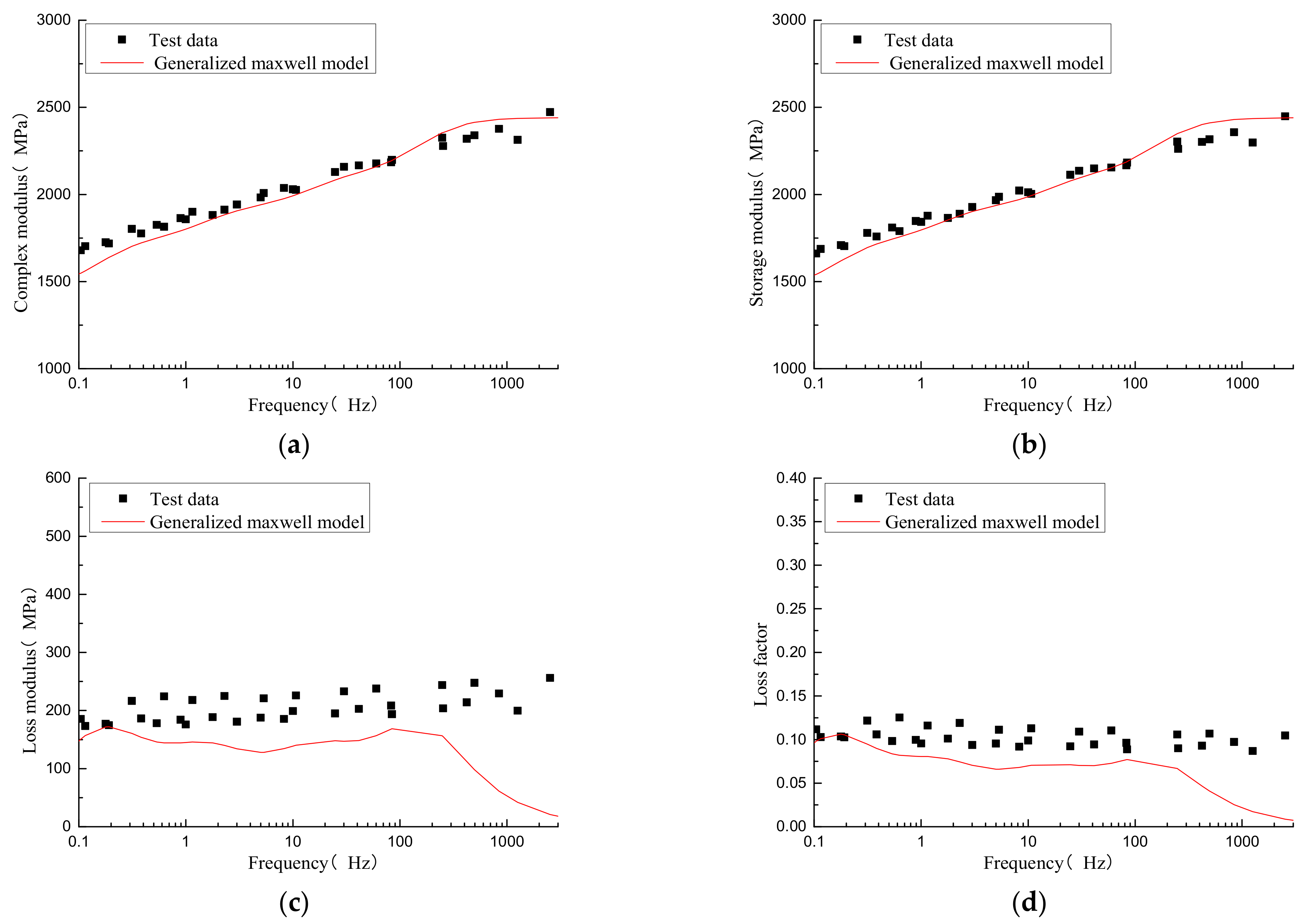
Taking the parameters and test data at 15 °C as an example (Figure 2), from the test data, it can be clearly seen that the modulus of the composite sleeper is frequency dependent—the higher the loading frequency, the larger the modulus. According to the generalized Maxwell model, the complex modulus and storage modulus fit well. The loss modulus and loss factor characterization accuracy are relatively low, especially in the high-frequency range. This will mean the generalized Maxwell model will be unable to fully reflect the damping properties of the composite sleeper in the high-frequency range. However, using the generalized Maxwell model to characterize the mechanical parameters of composite sleepers is obviously better than considering them as constants in the whole frequency range. In the following theoretical model for the composite sleeper-ballasted track, the viscoelastic properties of composite sleepers will be considered.

3. Model and Calculation Method

A vertical vehicle–track dynamic coupling model (Figure 3) was established in LS-DYNA software to investigate the vibration energy of the composite sleeper-ballasted track.

3.1. Vehicle Model

The vehicle model consists of one car body, two bogies, four wheelsets, four primary suspension systems, and two secondary suspension systems [29,30]. It was developed according to multibody dynamic theory [30,31,32,33]. The wheelsets, bogies, and car body are simplified as rigid bodies. The primary suspension and secondary suspension systems are modeled as spring–damper elements. The vehicle model has 10 degrees of freedom (DOF), which are the vertical and pitch motion of the car body and the bogies and the vertical motion of the wheelsets. The vehicle adopts the China Railway High-speed (CRH) 2 vehicle, which is widely used in high-speed railways in China; the speed is 250 km/h and its parameters are shown in Table 2.

3.2. Track Model

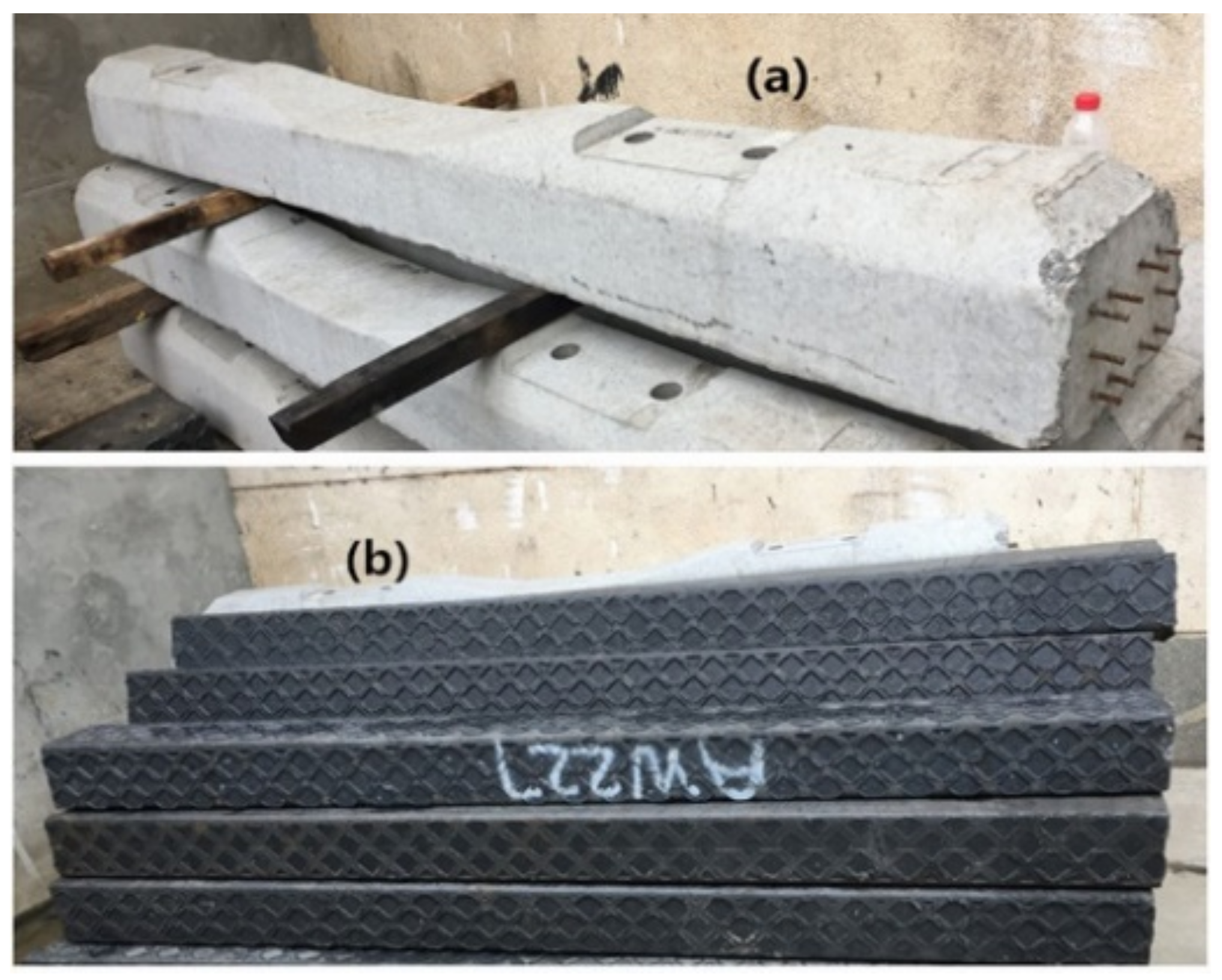
The composite sleeper-ballasted track consists of a rail, fastener systems, composite sleeper, ballast bed, and subgrade. In the track model, the rail is simplified to a point-supported Euler beam. The sleepers are simulated by solid elements. Considering their viscoelastic properties, the generalized Maxwell model is used to characterize the constitutive relation. The parameters are shown in Table 1. The fasteners are simplified to spring–damper elements. The ballast bed are simplified to discrete masses and spring–damper elements; in order to account for the coupling effects of the interlocking ballast granules and the continuity, shear stiffness and shear damping coupling is introduced between adjacent ballast masses [31,34]. The subgrades are also simplified to spring–damper elements. The widely used type-III pre-stressed concrete sleepers in China are also calculated in the model for comparison; two types of sleepers are shown in Figure 4. The parameters of the track structures are shown in Table 3.

3.3. Wheel–Rail Interaction

The wheel–rail interaction is based on the compression between a wheel and rail. The nonlinear Hertzian elastic contact theory [31,35,36] is used to calculate the wheel–rail force. Therefore, the wheel–rail force is simulated by Equations (4) and (5):
[ 1 G H e r t z Δ Z ( t ) ] 3 / 2 ,   Δ Z ( t ) > 0 0 , Δ Z ( t ) 0
Δ Z ( t ) = Z w ( t ) Z r ( t ) η ( t )
where G H e r t z is the contact constant of the wheel and rail (m/N2/3), Δ Z ( t ) is the normal compression at the wheel–rail contact point, Z w ( t ) is the vertical displacement of the wheel, Z r ( t ) is the vertical displacement of the rail at the relevant contact point, and η ( t ) is the track vertical irregularity.
As we know, random track irregularities exist in railway lines everywhere and influence the dynamic performance of the vehicle–track system. Therefore, random track irregularities should be considered in the vehicle–track coupled model. The German High-speed Railway low irregularity is adopted. The power spectrum density (PSD) function of the German HSR low irregularity is expressed as follows [30]:
S v ( Ω ) = A v Ω c 2 ( Ω 2 + Ω r 2 ) ( Ω 2 + Ω c 2 )
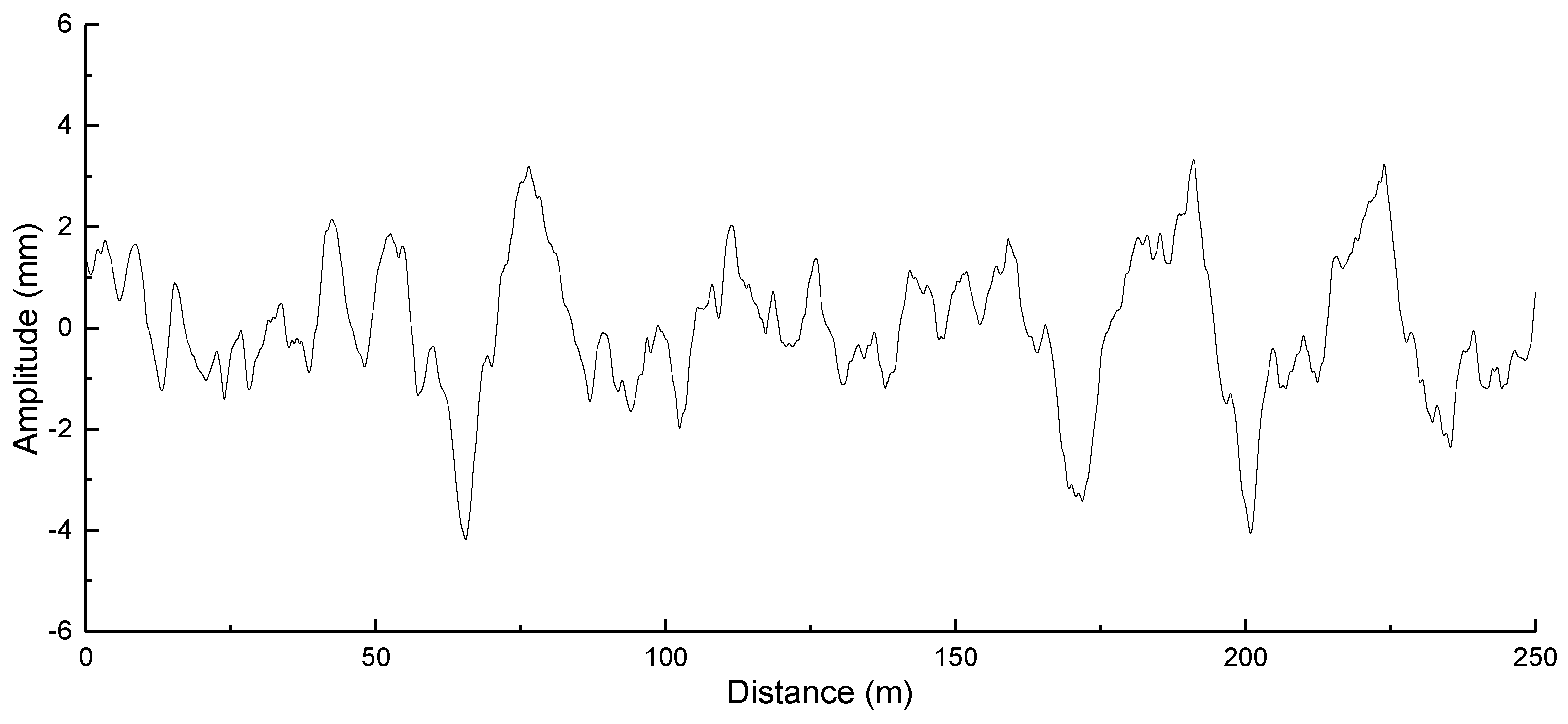
where Ω c , Ω r , and Ω denote the cut-off frequencies of track irregularities, while Av denotes the roughness constant of track elevation irregularities. In Equation (6), Ω c = 0.8246   ( rad / m ) , Ω r = 0.0206   ( rad / m ) , and A v = 4.032 × 10 7   ( m 2 .   Rad / m ) . The PSD function would be transformed into vertical irregularities along the longitudinal distance of the track by means of a time–frequency transformation technique, as shown in Figure 5.

3.4. Model Validation

In order to verify the validity of the vehicle–track dynamic coupling model, the simulation results for the composite sleeper-ballasted track are compared with the results in the literature [17] (as shown in Table 4) under the same conditions. It can be observed that the dynamic responses calculated by the model in this paper are relatively close to those in the literature [17]. Therefore, the model in this paper can effectively describe the dynamic response of the track structure.

3.5. Calculation Method

The power flow calculation method of the track structure refers to the work in [24,25,26]. Based on the vehicle–track dynamic coupling model, the node velocity and spring force in the time domain are obtained, and through the Fourier transform, the node velocity and spring force in the frequency domain are obtained. According to Equation (7), the power flow can be obtained as follows:
P i ( k ) = 1 2 R e [ F i ( k ) V i * ( k ) ]
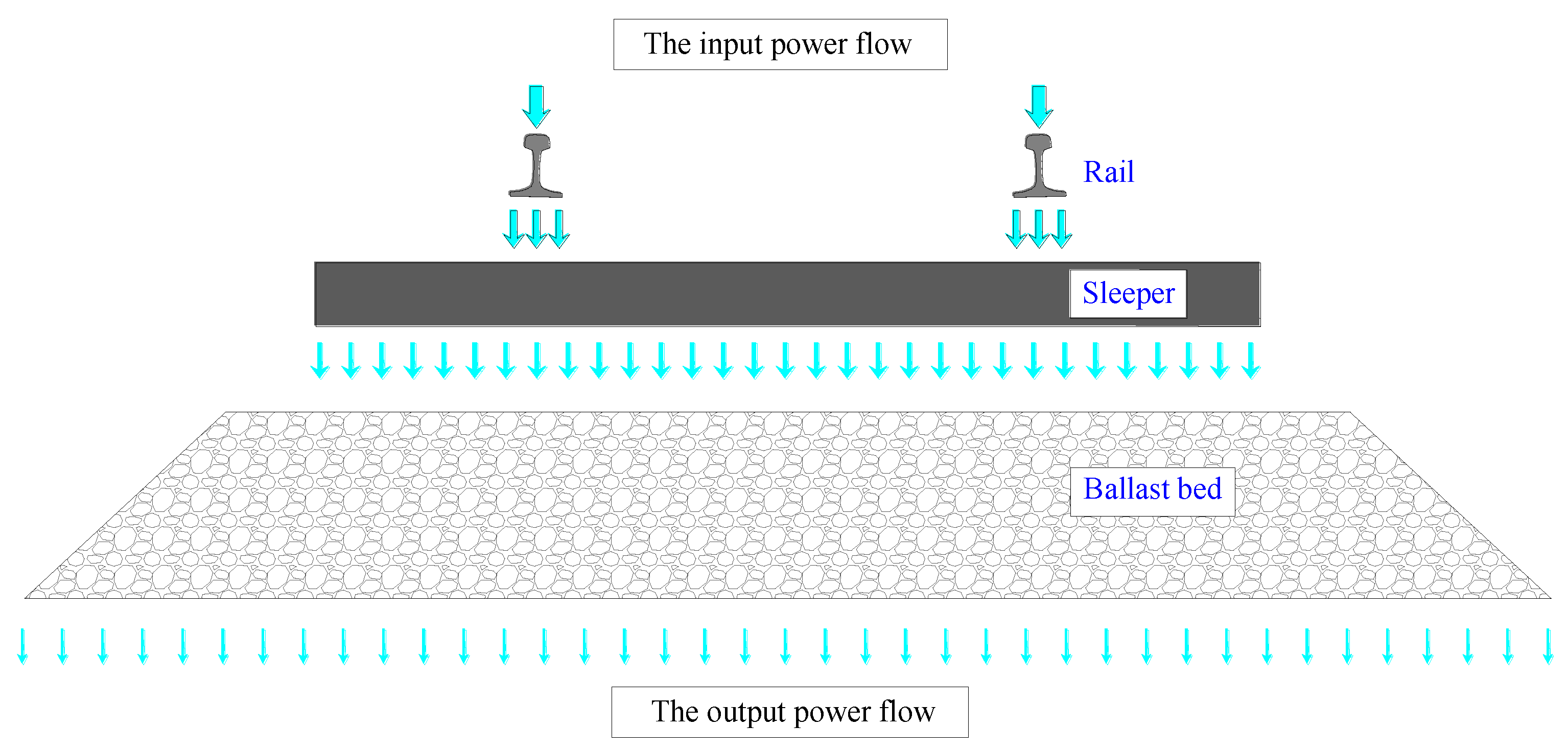
where F i denotes the complex force of the ith node, Vi denotes the complex velocity of the ith node in the frequency domain, V i * denotes the conjugation of V i , k denotes the sample frequency point, and Re represents the real part of the power flow value. It is necessary to pay attention to the calculation of the power flow; the node velocity and the spring force should correspond exactly. In order to investigate the influence of the composite sleeper-ballasted track under the wheel–rail interaction, it is necessary to choose a certain area. This paper selects the area of a sleeper for calculation. A rail and ballast bed connected by a single sleeper are used as the calculation area. The rail power flow is the total power flow of the rail nodes connected to the fasteners, and the sleeper input power flow is the total power flow of the sleeper nodes connected to the fasteners; similarly, the sleeper output power flow is the total power flow of the sleeper nodes connected to the ballast bed, and the ballast bed power flow is the sum of the ballast bed nodes. The power flow transmission of the track structure is shown in Figure 6, and the total power flow of each structural layer is calculated as follows:
P ( k ) = 1 2 i = 1 n R e [ F i ( k ) V i * ( k ) ]
where n is the total number of nodes and i is the sequence number corresponding to the node.
In order to make the comparison obvious, the relative power flow should be calculated. The calculation formula for the relative power flow is as follows:
P r ( k ) = 10 log P ( k ) P 0
where P ( k ) is the total power flow and P 0 is the reference value, which is equal 1.0 × 10⁻¹² N∙m/s.

4. Results and Discussion

4.1. Considering the Influence of the Viscoelastic Properties of Composite Sleepers on the Dynamic Characteristics of the Track Structure

In order to analyze the influence of the viscoelastic properties of composite sleepers on the power flow of the track structure, at the same time considering that 15 °C is close to the annual average temperature of many regions in China, the mechanical parameters of composite sleepers at 15 °C and the mechanical parameters are considered as constants are selected for comparison. The constant elastic modulus of the composite sleeper is 2000 MPa and the loss factor is 0.12. According to the above description, the vehicle–track dynamic coupling model is adopted to calculate the power flow of the track structure.
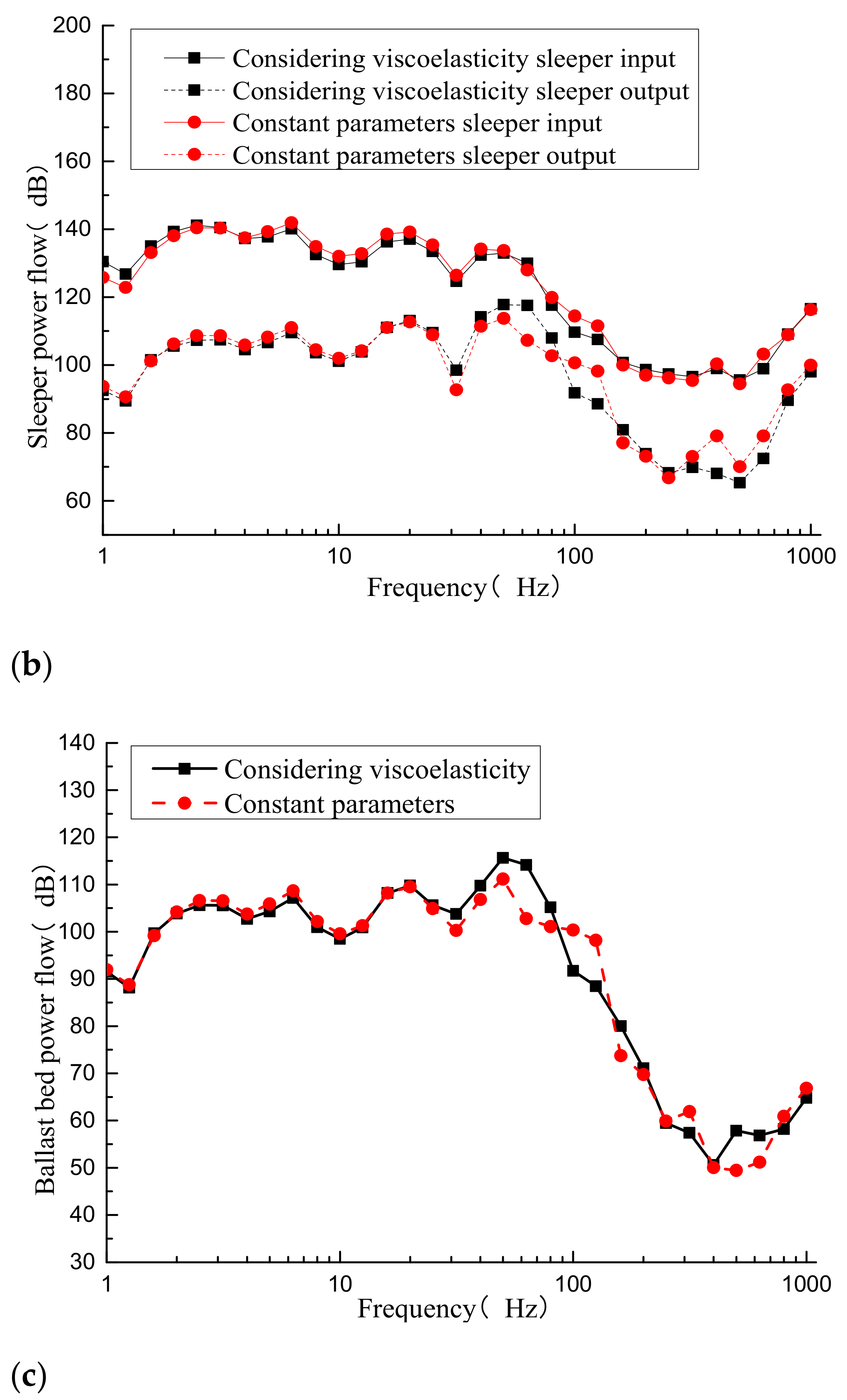
It can be seen from Figure 7a that compared with the constant parameters, a value of below 100 Hz for the viscoelastic properties of the composite sleeper would slightly reduce the rail power flow. Above 100 Hz, the rail power flow would increase slightly. The composite sleeper’s viscoelastic properties have little effect on the rail power flow.
After obtaining the fastener spring force and the speed of the corresponding sleeper node, the sleeper input power flow can be obtained by calculation. Similarly, the spring force of the lower support of the sleeper and the speed of the corresponding sleeper node can be obtained, then the sleeper output power flow can be obtained, as shown in Figure 7b. It can be seen that compared with the constant parameters, when considering the viscoelastic properties of the sleeper, the composite sleeper input and output power flows vary greatly; in most frequency ranges, the sleeper input power flow is reduced. At 100 Hz, the sleeper input power flow is reduced by 4.7 dB. Considering the composite sleeper’s viscoelastic properties, the sleeper output power flow is affected more at above 50 Hz. At 63 Hz, the sleeper output power flow is increased by 10.2 dB. At 400 Hz, the sleeper output power flow is reduced by 11.0 dB. Overall, the composite sleeper’s viscoelastic properties increase the power flow consumption of the composite sleeper (input power flow minus output power flow).
Figure 7c shows the ballast bed power flow. Compared with the constant parameters of the composite sleeper, the viscoelastic properties of composite sleeper have little influence on the ballast bed power flow in most frequency ranges; however, they vary greatly in some frequency ranges. For example, at 63 Hz, the ballast bed power flow increases by 11.3 dB, and at 100 Hz the ballast bed power flow decreases by 8.6 dB.

4.2. Comparative Analysis of Composite Sleeper and Type-III Sleeper-Ballasted Track

The advantages of composite sleepers include their excellent elasticity, which can increase the elasticity of the track structure and reduce the vibration of the substructure. In order to analyze the effect of the use of the composite sleeper track, its viscoelastic properties are considered and compared with the most widely used type-III concrete sleeper track in China.
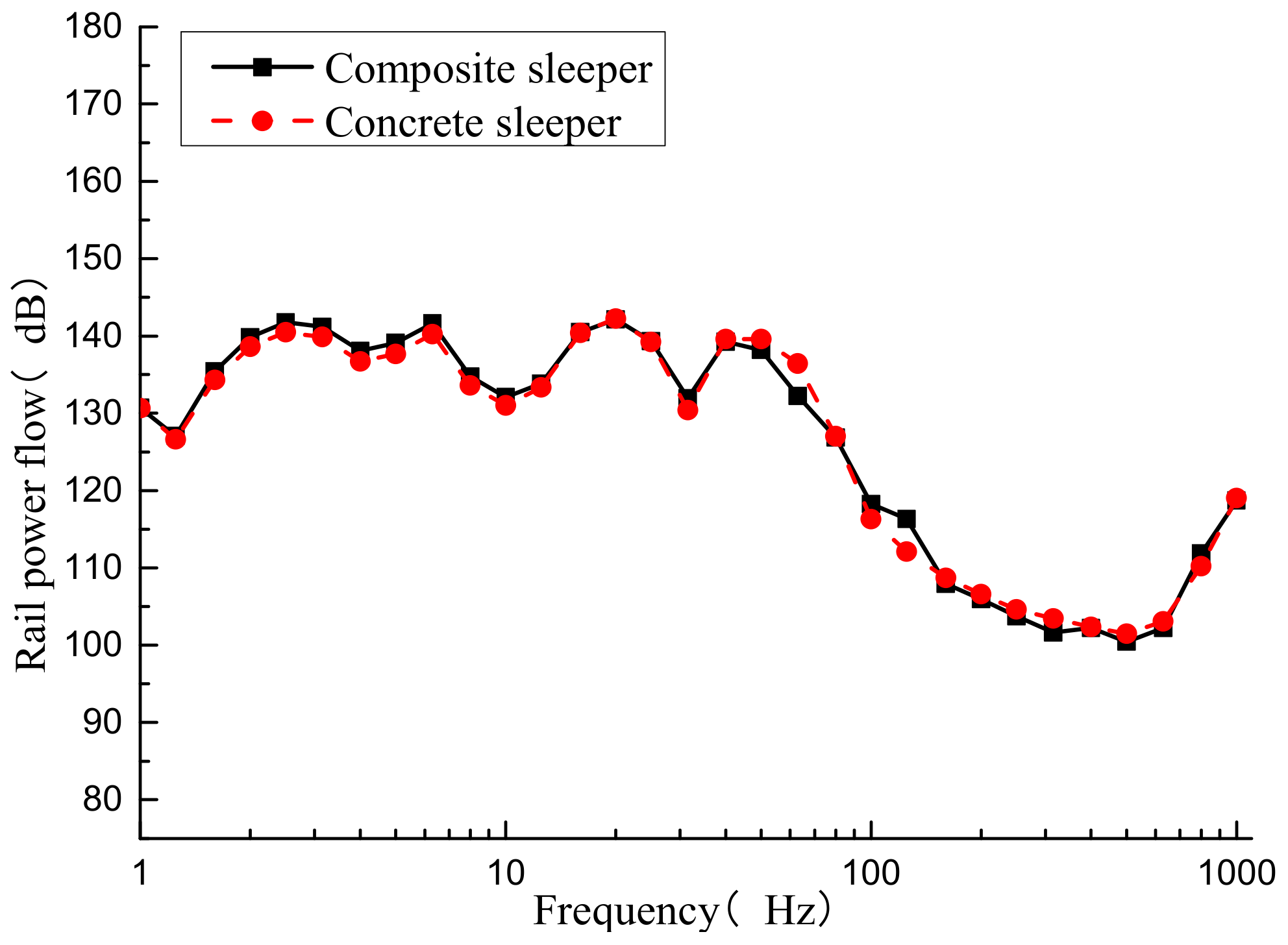
For convenience of comparison, the rail power flow values of the composite sleeper and type-III pre-stressed concrete sleeper-ballasted track at one-third octave frequency are shown in Figure 8. The rail power flow values are mainly concentrated below 100 Hz. At most center frequencies, the rail power flow values of the two tracks are relatively close. In a certain frequency range, the rail power flow changes slightly. At the center frequency of 63 Hz, the rail power flow of the composite sleeper-ballasted track is 4.2 dB less than that of the concrete sleeper-ballasted track. At the center frequency of 125 Hz, the former is 4.2 dB larger than the latter. From the perspective of the rail vibration energy, the use of the composite sleeper has little effect on the rail power flow.
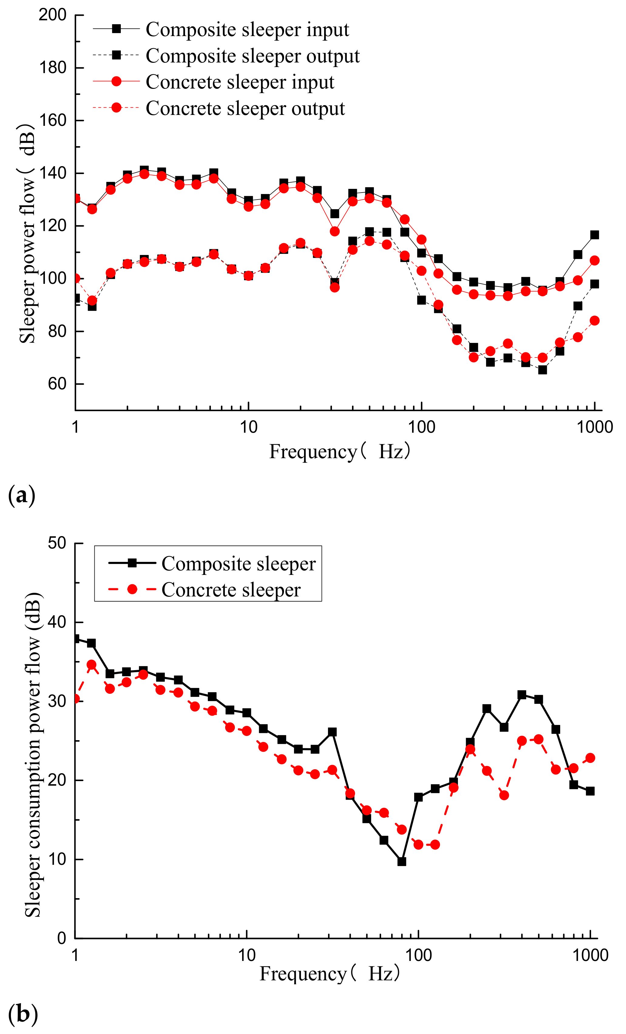
A comparison of the sleeper power flow values of the two ballasted tracks is shown in Figure 9. It can be observed that the composite sleeper input power flow is larger than that of the concrete sleeper at most of the center frequencies. This is due to the smaller mass of the composite sleeper when the wheel–rail forces are similar, resulting in a larger vibration velocity on the upper surface of the composite sleeper. At the center frequency of 800 Hz, the composite sleeper input power flow increases by 9.8 dB. The composite sleeper output power flow is close to or even smaller than that of the concrete sleeper at most of the center frequencies, which is caused by the elasticity and damping effects of the composite sleeper, while the power flow is more greatly consumed in the composite sleeper’s internal transmission process. It can be clearly seen from Figure 9b that the internal vibration energy consumption for the composite sleeper is significantly larger than that of the concrete sleeper. At 315 Hz, the composite sleeper consumption power flow is 8.6 dB larger than that of the concrete sleeper. The above analysis can clarify the characteristics of energy transfer inside the composite sleeper. The vibration energy transmitted from the upper part to the composite sleeper is not reduced, and is even slightly larger than the concrete sleeper. The composite sleeper uses its own physical characteristics and the energy consumed by the vibration process is significantly larger than the concrete sleeper; compared with the concrete sleeper, in some frequency ranges, the energy transmitted downward from the composite sleepers is reduced.
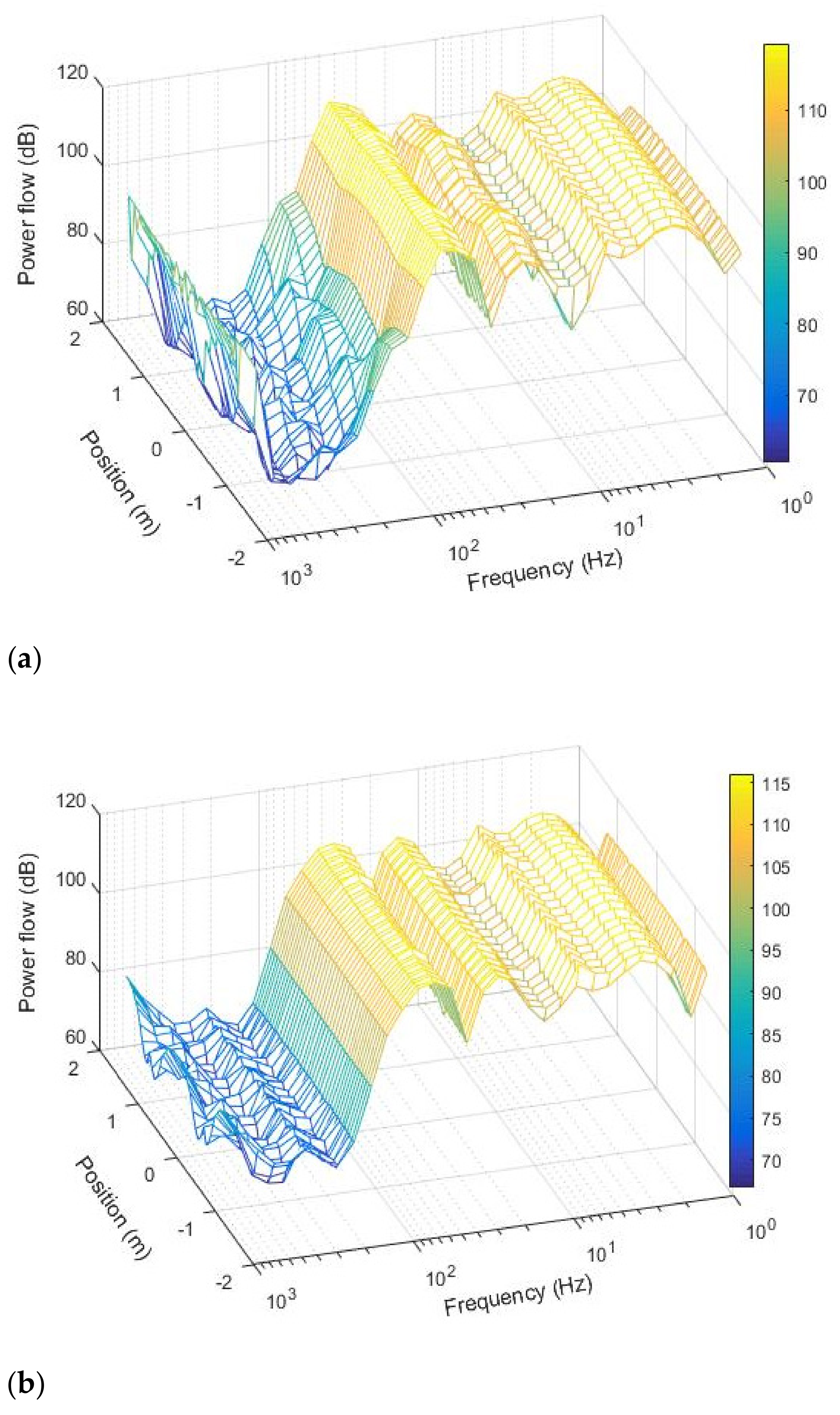
In order to investigate the power flow distribution of the sleeper under vehicle loading, the power flow of each node in the longitudinal sections of the bottom of the sleeper was calculated. In this way, the power flow of each section along the longitudinal direction of the sleeper can be obtained. Taking the longitudinal section of the sleeper, the frequencies, and the power flow as the x, y, and z coordinates, respectively, the power flow distribution along the longitudinal direction of the sleeper can be obtained, as shown in Figure 10.
It can be observed from the figure that the vibration energy values of the sleeper are mainly concentrated in the range of 1–100 Hz, and that there are many peaks at different center frequencies, which are related to the track irregularity, track structure, and vehicle. At many center frequencies, the power flow of the composite sleeper at the rail–seat section is the largest, while the power flow to the center and the end of the sleeper gradually decreases. This is due to the energy being transferred from the rail to the sleeper through the fastener system; however, the power flow of the concrete sleeper distribution is not obvious, and the power flow is more evenly distributed along the longitudinal direction. This is due to the fact that the concrete sleeper is closer to rigid than the composite sleeper and closer to the overall vertical vibration. It can be observed from Figure 10 that the vibration power flow of the composite sleeper is quite different. The power flow of the composite sleeper at the rail–seat section is large, which is likely to cause fatigue damage under long-term vehicle loading. This issue requires attention.
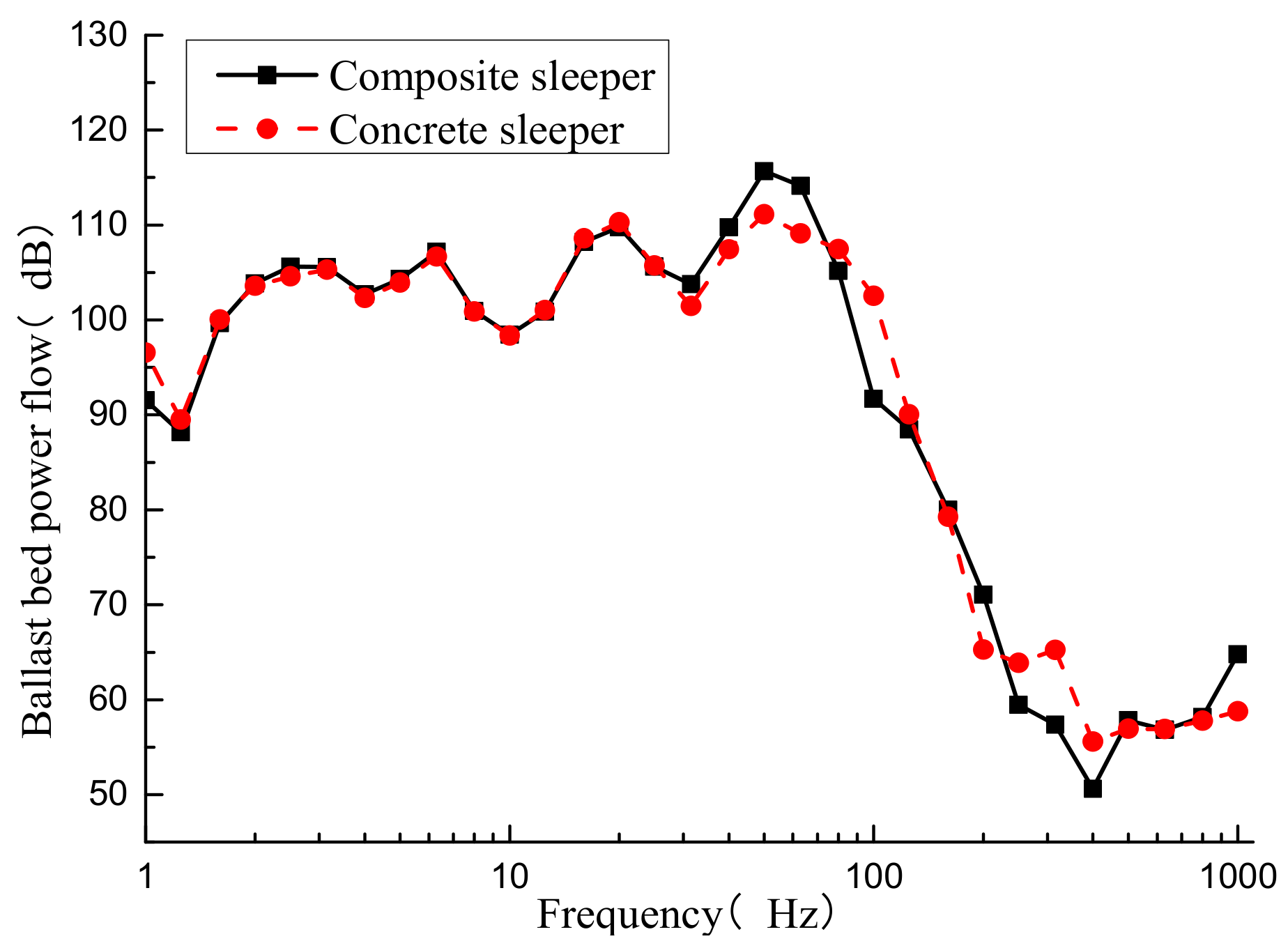
The ballast bed power flow of the composite sleeper and concrete sleeper-ballasted track is shown in Figure 11. The ballast bed power flow values of the composite sleeper-ballasted track in the ranges of 80–125 Hz and 250–400 Hz are smaller than those of the concrete sleeper-ballasted track; however, in the ranges of 40–63 Hz and 800–1000 Hz, the former’s values are larger than the latter’s, and the ballast bed power flow values of the two tracks are closer at the other center frequencies. From the perspective of power flow, the use of composite sleepers consumes a great deal of the vibration from the sleeper itself, which reduces the vibration energy in the ballast bed, especially in the middle frequency bands. This is beneficial to slowing down the pulverization of the ballast bed.

4.3. Comparative Analysis of Composite Sleeper Track under Different Temperatures

The DMA test shows that the mechanical parameters of the composite sleeper are sensitive to temperature. Its modulus is larger at low temperatures and smaller at high temperatures. Therefore, it is necessary to analyze the vibration characteristics of composite sleeper-ballasted track at different temperatures. In this section, the mechanical parameters of tested and characterized composite sleepers at 5, 15, and 25 °C are selected and calculated based on the above model to obtain the power flow of the track structure at different temperatures.
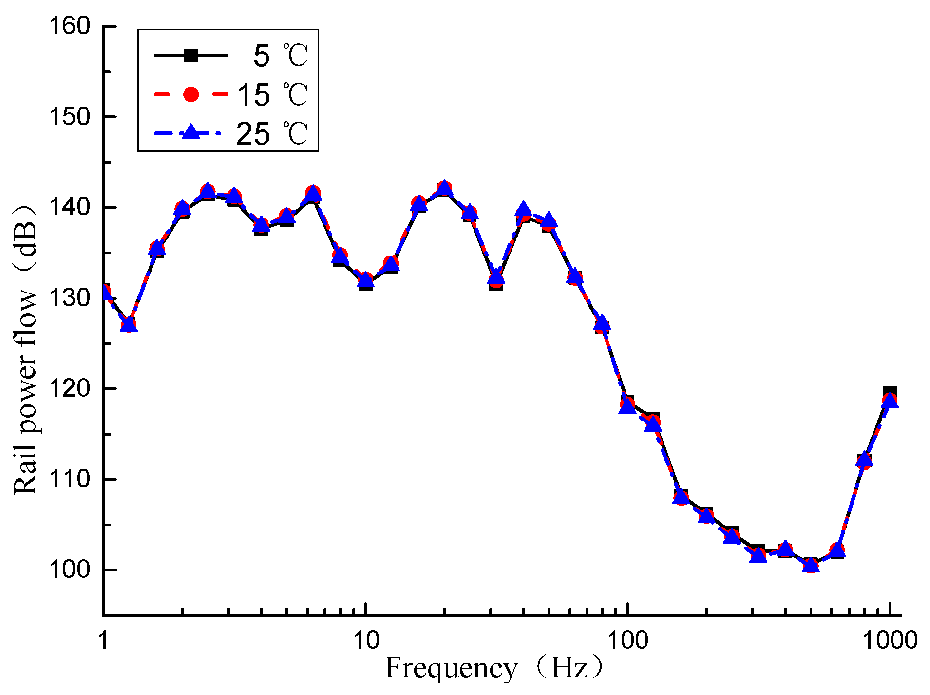
Figure 12 shows the rail power flow at different temperatures. It can be seen from the figure that the change of the composite sleeper’s mechanical parameters caused by the temperature has a small effect on the rail power flow and only produces a small amount in individual frequency ranges. For example, at the center frequency of 40 Hz, the rail power flow values at 5 and 15 °C are reduced by 0.67 and 0.40 dB, respectively, compared with that at 25 °C.
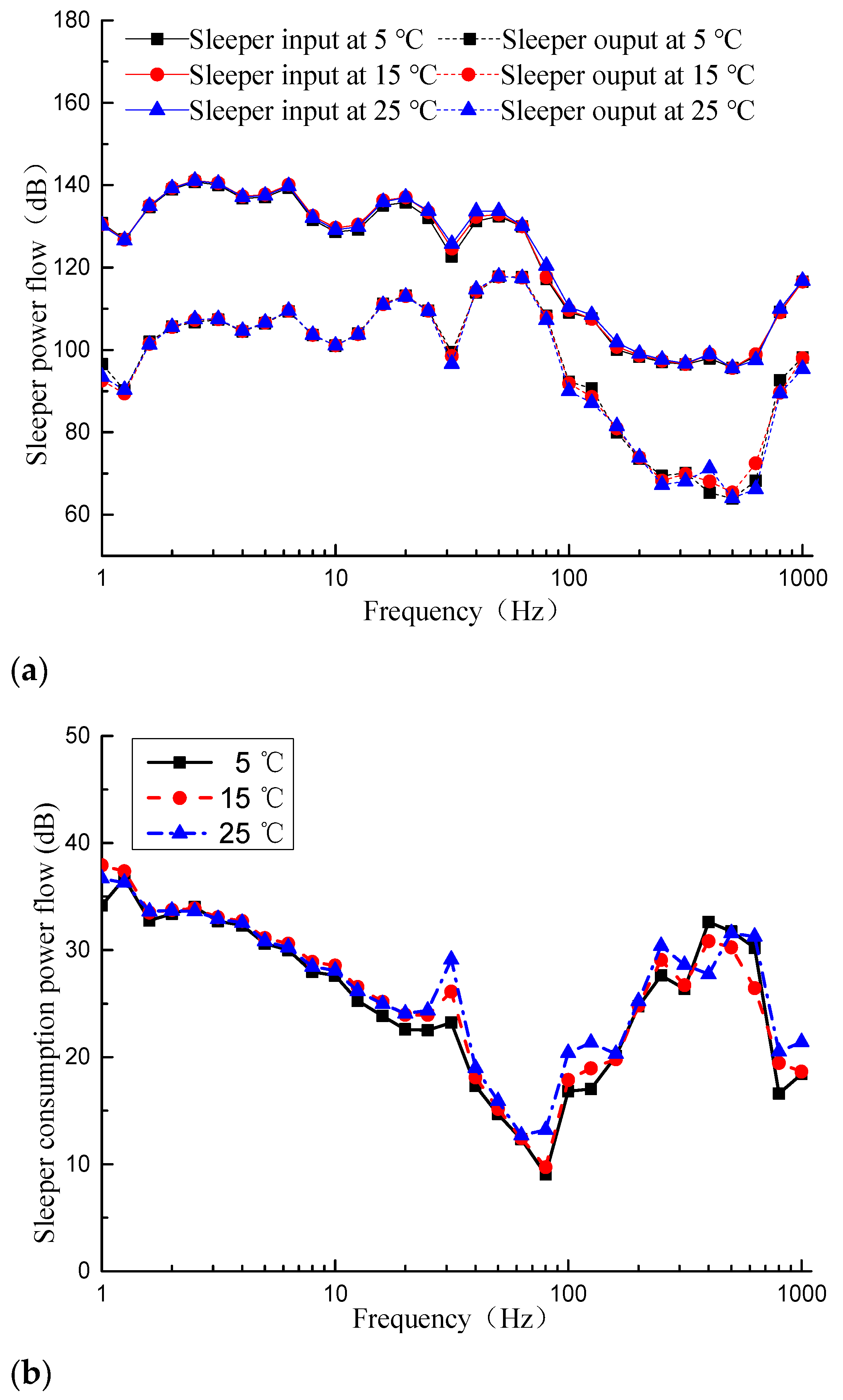
From Figure 13, the composite sleeper power flow values at different temperatures show that as the temperature increases, the input and output power flow of the sleeper hardly change in the frequency range below 31.5 Hz, while in the frequency range above 31.5 Hz, the power flow changes slightly. As the temperature increases, the sleeper input power flow shows an increasing trend; however, the sleeper output power flow shows a decreasing trend. At the center frequency of 80 Hz, the sleeper input power flow values at 5 and 15 °C are reduced by 3.2 dB and 2.8 dB, respectively, compared with that at 25 °C. At a center frequency of 125 Hz, the sleeper output power flow values at 5 and 15 °C are increased by 3.5 dB and 1.5 dB, respectively, compared with that at 25 °C. It can be seen from Figure 13b that as the temperature increases, the power flow of the sleeper transmission loss shows an increasing trend. This also shows that the smaller the modulus of the composite sleeper, the larger the internal power flow consumption. At the center frequency of 31.5 Hz, the loss power flow values of sleepers at 5 and 15 °C decrease by 5.8 dB and 3.0 dB, respectively, compared with at 25 °C.
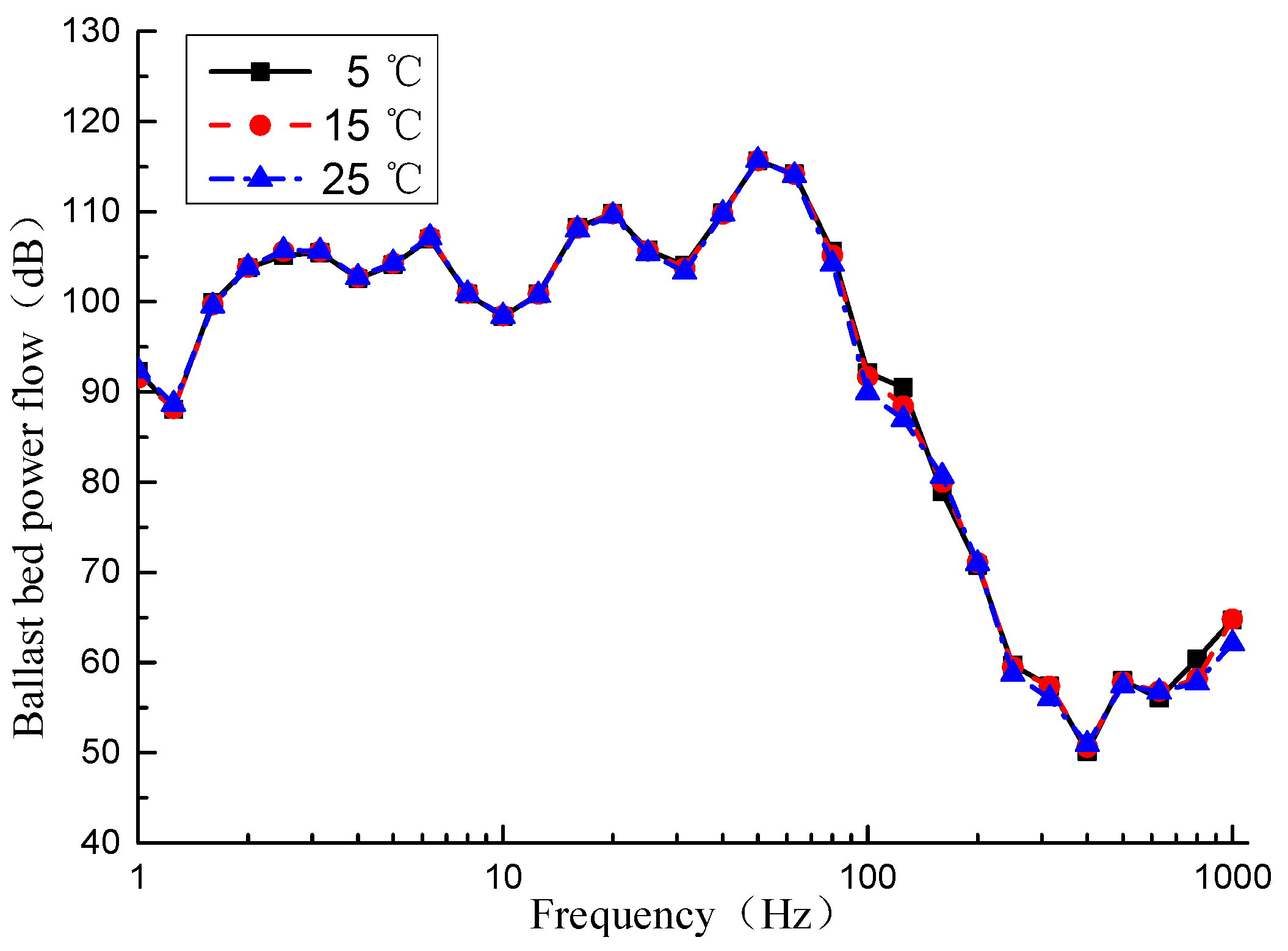
Figure 14 shows the ballast bed power flow. It can be seen that in most frequency ranges, temperature changes have little effect on the ballast bed power flow. In some frequency ranges, as the temperature increases, the ballast bed power flow decreases. At a center frequency of 125 Hz, the ballast bed power flow values at 5 and 15 °C are increased by 3.5 dB and 1.4 dB, respectively, compared with 25 °C. On the whole, the higher the temperature, the better the vibration reduction effect of the ballast bed.
In summary, the temperature change mainly affects the power flow of the composite sleeper track structure in the frequency range above 50 Hz. The temperature change has little effect on the rail or ballast bed. However, the impact on the sleeper power flow is slightly greater. The higher the temperature, the smaller the modulus of the sleeper and the better the vibration reduction effect of the track bed.

5. Conclusions

To investigate the vibration performance of the composite sleeper-ballasted track, the vehicle–track dynamic coupling model was established with consideration of the viscoelastic properties of the composite sleeper. Compared with the traditional type-III pre-stressed concrete sleeper, the power flow method was used to reveal the vertical distribution and the power flow transfer characteristics of the composite sleeper-ballasted track. The main conclusions are as follows:
(1) From the perspective of the power flow of the track structure, the viscoelastic properties of the composite sleeper have a small effect on the rail power flow and have a greater impact on the power flow of the sleeper and the ballast bed in some frequency ranges. In the analysis, the viscoelastic properties of the composite sleeper should be considered, which can effectively improve the calculation accuracy of the power flow of the track structure;
(2) Due to its own physical characteristics, the energy consumed by the vibration process of the composite sleeper is larger than that of the type-III pre-stressed concrete sleeper, which reduces the power flow of the ballast bed, especially in the ranges of 80–125 Hz and 250–400 Hz. This is beneficial to slowing down the pulverization of the ballast bed;
(3) The power flow of the composite sleeper varies greatly along the longitudinal distribution; however, the power flow of the concrete sleeper is more evenly distributed along the longitudinal direction. The excessive vibration energy from the composite sleeper’s rail–seat section may cause fatigue damage under long-term vehicle loading, requiring increased attention;
(4) The temperature change mainly affects the power flow of the composite sleeper track structure in the frequency range above 50 Hz and has little effect on the rail or ballast bed. Relatively speaking, it has a slightly greater impact on the sleeper power flow. The higher the temperature, the smaller the modulus of the composite sleeper and the better the vibration reduction effect of the track bed;
In this paper, the power flow method was used to investigate the vibration characteristics of composite sleeper-ballasted tracks in high-speed railways. In the future, the vibration characteristics of a composite sleeper-ballasted track in a heavy haul railway or subway could be investigated to provide theoretical guidance for the further use of composite sleepers in China.

Author Contributions

Conceptualization, Z.Z., Y.G. and C.L.; methodology, Z.Z. and C.L.; software, Z.Z. and Y.G.; validation, Z.Z., Y.G. and C.L.; formal analysis, Z.Z.; investigation, Z.Z. and C.L.; data curation, Z.Z.; writing—original draft preparation, Z.Z.; writing—review and editing, Y.G. and C.L.; visualization, Z.Z.; supervision, C.L.; funding acquisition, C.L. All authors have read and agreed to the published version of the manuscript.

Funding

This research was funded by the National Natural Science Foundation of China, grant number 51778543, and Chengdu–Lanzhou Railway Special Project, grant number CLRQT-2016-006.

Acknowledgments

The authors express gratitude to Rongshan Yang and Wei Qi for their valuable suggestions.

Conflicts of Interest

The authors declare no conflict of interest.

References

  1. Newby, P.R.T.; Stölzel, R. Modern Railway Track. Photogramm. Rec. 2003, 18, 81–83. [Google Scholar] [CrossRef]
  2. Qiao, P.; Davalos, J.F.; Zipfel, M.G. Modeling and optimal design of composite-reinforced wood railroad crosstie. Compos. Struct. 1998, 41, 87–96. [Google Scholar] [CrossRef]
  3. Ferdous, W.; Manalo, A. Failures of mainline railway sleepers and suggested remedies—Review of current practice. Eng. Fail. Anal. 2014, 44, 17–35. [Google Scholar] [CrossRef]
  4. Bolin, C.A.; Smith, S.T. Life Cycle Assessment of Creosote-Treated Wooden Railroad Crossties in the US with Comparisons to Concrete and Plastic Composite Railroad Crossties. J. Transp. Technol. 2013, 3, 149–161. [Google Scholar] [CrossRef] [Green Version]
  5. Manalo, A.; Aravinthan, T.; Karunasena, W.; Ticoalu, A. A review of alternative materials for replacing existing timber sleepers. Compos. Struct. 2010, 92, 603–611. [Google Scholar] [CrossRef]
  6. Ferdous, W.; Manalo, A.; Van Erp, G.; Aravinthan, T.; Kaewunruen, S.; Remennikov, A. Composite railway sleepers—Recent de-velopments, challenges and future prospects. Compos. Struct. 2015, 134, 158–168. [Google Scholar] [CrossRef]
  7. Xiao, S.L.; Lin, H.; Shi, S.Q.; Cai, L. Optimum processing parameters for wood-bamboo hybrid composite sleepers. J. Reinf. Plast. Compos. 2014, 33, 2010–2018. [Google Scholar] [CrossRef]
  8. Ferdous, W.; Manalo, A.C.; Van Erp, G.; Aravinthan, T.; Ghabraie, K. Evaluation of an Innovative Composite Railway Sleeper for a Narrow-Gauge Track under Static Load. J. Compos. Constr. 2018, 22, 04017050. [Google Scholar] [CrossRef]
  9. Lotfy, I.; Farhat, M.; Issa, M.A. Effect of pre-drilling, loading rate and temperature variation on the behavior of railroad spikes used for high-density-polyethylene crossties. Proc. Inst. Mech. Eng. Part F J. Rail Rapid Transit 2016, 231, 44–56. [Google Scholar] [CrossRef]
  10. Lotfy, I.; Farhat, M.; Issa, M.A.; Al-Obaidi, M. Flexural behavior of high-density polyethylene railroad crossties. Proc. Inst. Mech. Eng. Part F J. Rail Rapid Transit 2015, 230, 813–824. [Google Scholar] [CrossRef]
  11. Lotfy, I.; Farhat, M.; Issa, M.A. The effect of temperature on the performance of glass-fiber-reinforced high-density polyethylene composite railroad crossties. Proc. Inst. Mech. Eng. Part F J. Rail Rapid Transit 2015, 230, 1145–1157. [Google Scholar] [CrossRef]
  12. Lotfy, I.; Issa, M.A. Evaluation of the longitudinal restraint, uplift resistance, and long-term performance of high-density poly-ethylene crosstie rail support system using static and cyclic loading. Proc. Inst. Mech. Eng. Part F J. Rail Rapid Transit 2017, 1–15. [Google Scholar] [CrossRef]
  13. Ferro, E.; Harkness, J.; Le Pen, L. The influence of sleeper material characteristics on railway track behaviour: Concrete vs. composite sleeper. Transp. Geotech. 2020, 23, 100348. [Google Scholar] [CrossRef]
  14. Kaewunruen, S.; You, R.; Ishida, M. Composites for Timber-Replacement Bearers in Railway Switches and Crossings. Infrastructures 2017, 2, 13. [Google Scholar] [CrossRef] [Green Version]
  15. Jing, G.; Qiang, W. Experiments and Optimize Analysis of Lateral Resistance of Composite Sleeper. Railw. Stand. Des. 2020, 64, 1–8. [Google Scholar]
  16. Zhao, Z.; Shen, Y.; Wei, Q.; Jiang, W.; Geng, H.; Li, C. Experimental study on dynamic performance of composite sleeper ballasted track. J. Cent. South Univ. Sci. Technol. 2019, 50, 234–240. [Google Scholar]
  17. Duan, H. Study on the Vertical Dynamic Behavior of Recycled Plastic Composite Crosstie Ballast Structure. Master’s Thesis, Southwest Jiaotong University, Chengdu, China, 2017. [Google Scholar]
  18. Zheng, J. The Methods to Increase the Elasticity of Ballast Track and Their influence on the Mechanical Properties of Ballast Track. Master’s Thesis, Southwest Jiaotong University, Chengdu, China, 2017. [Google Scholar]
  19. Goyder, H.; White, R. Vibrational power flow from machines into built-up structures, part II: Wave propagation and power flow in beam-stiffened plates. J. Sound Vib. 1980, 68, 77–96. [Google Scholar] [CrossRef]
  20. Goyder, H.; White, R. Vibrational power flow from machines into built-up structures, part I: Introduction and approximate analyses of beam and plate-like foundations. J. Sound Vib. 1980, 68, 59–75. [Google Scholar] [CrossRef]
  21. Li, W.; Lavrich, P. Prediction of Power Flows through Machine Vibration Isolators. J. Sound Vib. 1999, 224, 757–774. [Google Scholar] [CrossRef]
  22. Zhu, X.; Li, T.; Zhao, Y.; Yan, J. Vibrational power flow analysis of thin cylindrical shell with a circumferential surface crack. J. Sound Vib. 2007, 302, 332–349. [Google Scholar] [CrossRef]
  23. Yang, J.; Xiong, Y.; Xing, J. Vibration power flow and force transmission behaviour of a nonlinear isolator mounted on a nonlinear base. Int. J. Mech. Sci. 2016, 115, 238–252. [Google Scholar] [CrossRef]
  24. Fu, N.; Liu, Y.; Zhao, Z.; Li, C. Study of Vibration Energy Properties of Double-block Ballastless Damping Track. J. China Railw. Soc. 2018, 40, 111–118. [Google Scholar]
  25. Jiang, H.; Gao, L. Analysis of the Vibration Characteristics of Ballastless Track on Bridges Using an Energy Method. Appl. Sci. 2020, 10, 2289. [Google Scholar] [CrossRef] [Green Version]
  26. Jiang, H.; Gao, L. Study of the Vibration-Energy Properties of the CRTS-III Track Based on the Power Flow Method. Symmetry 2020, 12, 69. [Google Scholar] [CrossRef] [Green Version]
  27. Zhu, S.; Cai, C.; Luo, Z.; Liao, Z. A frequency and amplitude dependent model of rail pads for the dynamic analysis of train-track interaction. Sci. China Ser. E Technol. Sci. 2014, 58, 191–201. [Google Scholar] [CrossRef]
  28. Oregui, M.; De Man, A.; Woldekidan, M.; Li, Z.; Dollevoet, R. Obtaining railpad properties via dynamic mechanical analysis. J. Sound Vib. 2016, 363, 460–472. [Google Scholar] [CrossRef]
  29. Zhao, Z.; Shen, Y.; Yan, X.; Su, Q. Study on Vertical Dynamic Characteristics of Composite Sleeper Ballasted Track in Tunnels. In Proceedings of the 1st International Conference on Advances in Civil Engineering and Materials (ACEM1), Nanjing, China, 9–11 November 2018. [Google Scholar]
  30. Li, T.; Su, Q.; Kaewunruen, S. Saturated Ground Vibration Analysis Based on a Three-Dimensional Coupled Train-Track-Soil Interaction Model. Appl. Sci. 2019, 9, 4991. [Google Scholar] [CrossRef] [Green Version]
  31. Zhai, W.; Wang, K.; Cai, C. Fundamentals of vehicle–track coupled dynamics. Veh. Syst. Dyn. 2009, 47, 1349–1376. [Google Scholar] [CrossRef]
  32. Yang, S.-C.; Jang, S.-Y.; Kim, E. Determination of Upper Limit of Rail Pad Stiffness for Ballasted and Concrete Track of High-Speed Railway Considering Running Safety. J. Korean Soc. Railw. 2011, 14, 526–534. [Google Scholar] [CrossRef] [Green Version]
  33. Zhai, W.; Xia, H.; Cai, C.; Gao, M.; Li, X.; Guo, X.; Zhang, N.; Wang, K. High-speed train–track–bridge dynamic interactions—Part I: Theoretical model and numerical simulation. Int. J. Rail. Transp. 2013, 1, 3–24. [Google Scholar] [CrossRef]
  34. True, H. Vehicle-Track Coupled Dynamics. Veh. Syst. Dyn. 2020, 1–3. [Google Scholar] [CrossRef]
  35. Knothe, K.; Grassie, S.L. Modelling of Railway Track and Vehicle/Track Interaction at High Frequencies. Veh. Syst. Dyn. 1993, 22, 209–262. [Google Scholar] [CrossRef]
  36. Cai, X.; Zhong, Y.; Hao, X.; Zhang, Y.; Cui, R. Dynamic behavior of a polyurethane foam solidified ballasted track in a heavy haul railway tunnel. Adv. Struct. Eng. 2019, 22, 751–764. [Google Scholar] [CrossRef]
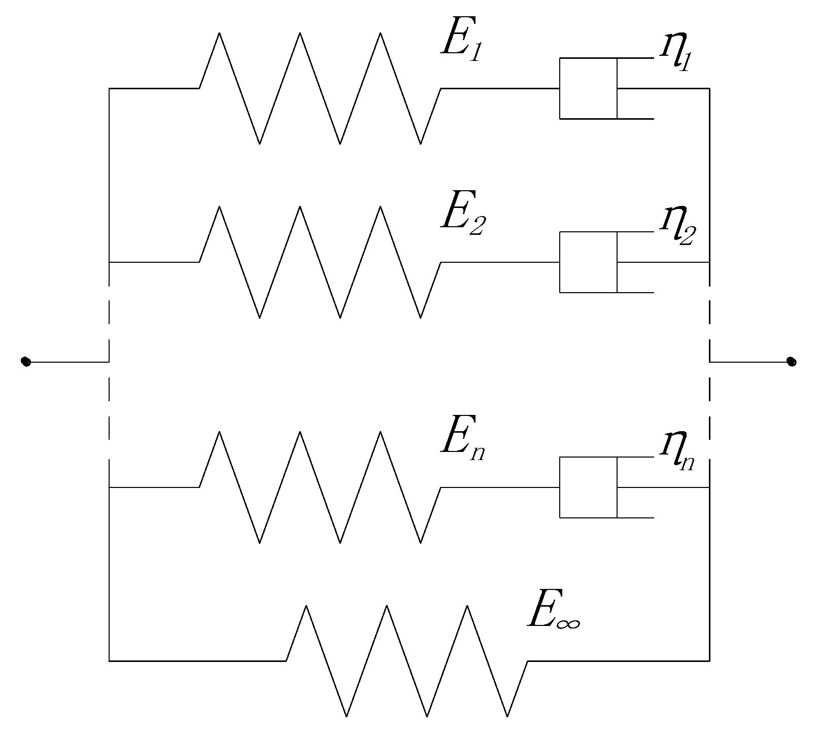
Figure 1. Generalized Maxwell model.
Applsci 11 00150 g001
Figure 2. Fitting curves of viscoelastic parameters of composite sleepers at 15 °C: (a) complex modulus; (b) storage modulus; (c) loss modulus; (d) loss factor.
Applsci 11 00150 g002
Figure 3. Vehicle–track dynamic coupling model.
Applsci 11 00150 g003
Figure 4. (a) Type-III pre-stressed concrete sleepers. (b) Composite sleepers.
Applsci 11 00150 g004
Figure 5. Track irregularity with distance.
Applsci 11 00150 g005
Figure 6. The transfer of the power flow.
Applsci 11 00150 g006
Figure 7. Power flow of track structure: (a) rail power flow; (b) sleeper input and output power flow; (c) ballast bed power flow.
Applsci 11 00150 g007aApplsci 11 00150 g007b
Figure 8. Rail power flow.
Applsci 11 00150 g008
Figure 9. Sleeper power flow: (a) sleeper input and output power flow; (b) sleeper consumption power flow.
Applsci 11 00150 g009
Figure 10. Sleeper longitudinal power flow distribution: (a) composite sleeper; (b) type-III pre-stressed concrete sleeper.
Applsci 11 00150 g010
Figure 11. Ballast bed power flow.
Applsci 11 00150 g011
Figure 12. Rail power flow.
Applsci 11 00150 g012
Figure 13. Sleeper power flow: (a) sleeper input and output power flow; (b) sleeper consumption power flow.
Applsci 11 00150 g013
Figure 14. Ballast bed power flow.
Applsci 11 00150 g014
Table 1. Generalized Maxwell model parameters (n = 4).
ParametersTemperature/°C
51525
E /MPa160014501200
E 1 /MPa480299278
τ 1 /s111
E 2 /MPa178188229
τ 2 /s0.10.10.1
E 3 /MPa150189125
τ 3 /s0.010.010.01
E 4 /MPa287315359
τ 4 /s0.0010.0010.001
Table 2. The main parameters of the China Railway High-speed (CRH) 2 vehicle.
NameUnitValue
Mass of car bodykg3.96 × 104
Mass of bogiekg3.5 × 103
Mass of wheelsetkg2.0 × 103
Pitching moment of inertia of carkg·m21.94 × 106
Pitching moment of inertia of bogiekg·m21.752 × 103
Vertical stiffness of primary suspensionN/m1.89 × 106
Vertical stiffness of secondary suspensionN/m1.176 × 106
Vertical damping of primary suspensionN·s/m1.96 × 104
Vertical damping of secondary suspensionN·s/m4.0 × 104
Fixed axle spacingm2.5 × 100
Bogie center distancem1.75 × 10
Wheel radiusm4.3 × 10−1
Table 3. The parameters of the track.
ParametersUnitValue
RailElastic modulusN/m22.06 × 1011
Moment of inertiam43.217 × 10−5
Mass per unit lengthkg/m6.064 × 10
Poisson ratio-3.0 × 10⁻¹
FastenerVertical stiffnessN/m6.0 × 107
Vertical dampingN·s/m7.5 × 104
Composite sleeperDensitykg/m31.097 × 103
Length/width/heightm2.7/0.22/0.18
Type-III sleeperElastic modulusN/m23.6 × 1010
Densitykg/m32.5 × 103
Poisson ratio-2.0 × 10⁻¹
Loss factor-1.0 × 10⁻²
Length/width/heightm2.6/0.3/0.23
Ballast bedMasskg6.5 × 102
Vertical stiffnessN/m2.4 × 108
Vertical dampingN·s/m6.0 × 104
Shear stiffnessN/m7.8 × 107
Shear dampingN·s/m8.0 × 104
SubgradeVertical stiffnessN/m2.4 × 108
Vertical dampingN·s/m6.0 × 104
Table 4. The maximum dynamic responses.
Dynamic ResponsesDuan [17]This Paper
Rail displacement (mm)1.411.38
Sleeper displacement (mm)0.900.87
Sleeper von Mises stress (MPa)1.451.12
Ballast bed displacement (mm)0.240.22
Publisher’s Note: MDPI stays neutral with regard to jurisdictional claims in published maps and institutional affiliations.