A Comparison of DER Voltage Regulation Technologies Using Real-Time Simulations

 ,
,  ,
,
Abstract
1. Introduction
- an unsupervised, volt–VAR (VV) function, defined by the IEEE 1547-2018 standard;
- the ProDROMOS particle swarm optimization optimal power flow (PSO OPF) method.
2. Voltage Regulation Methods
2.1. Autonomous Volt–VAR Control
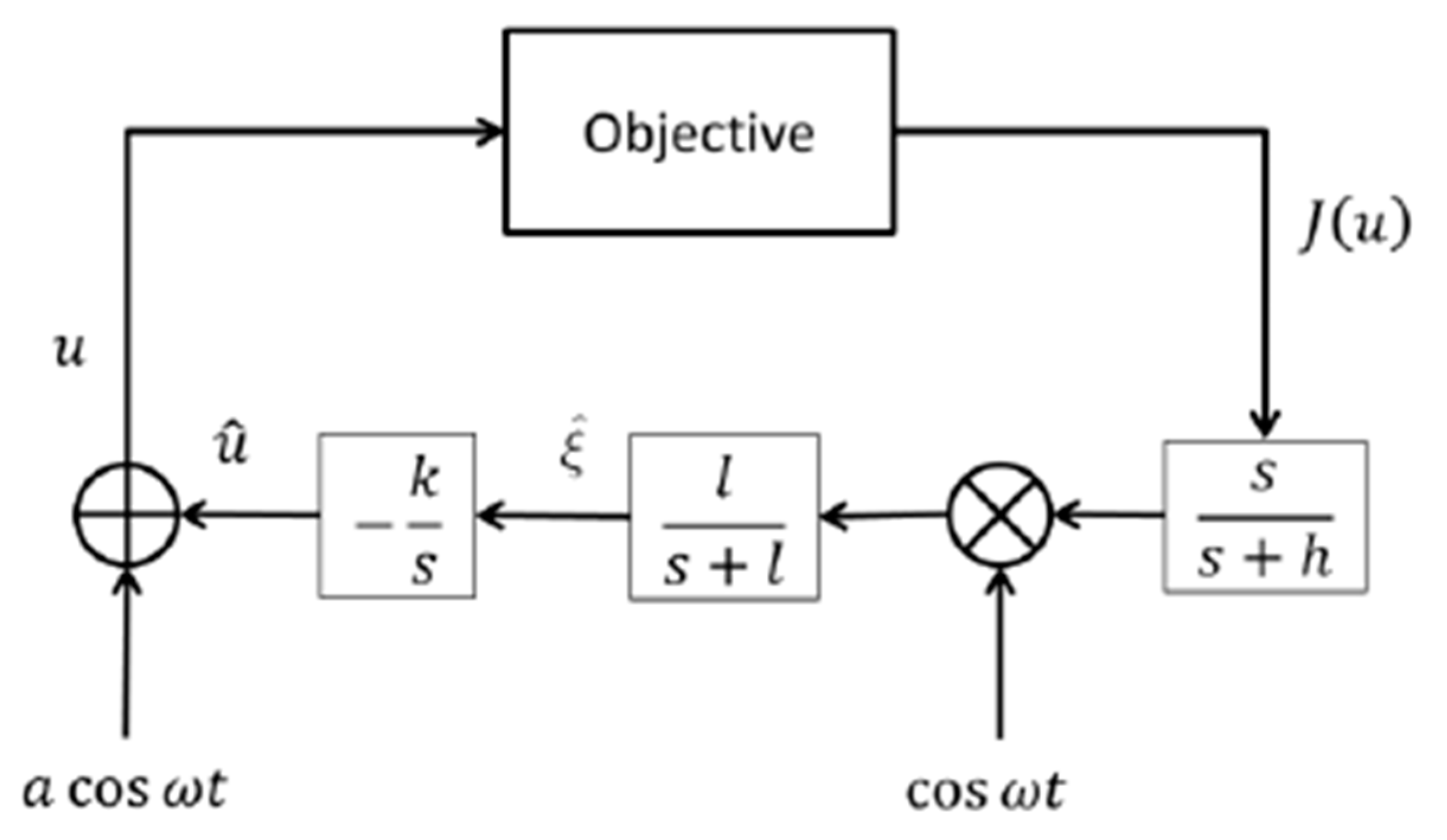
2.2. Extremum Seeking Control
Extremum Seeking Control Parameter Selection
- The ProDROMOS manager constructs the objective function, J.
- The ProDROMOS manager configures the DER with unique ωs to avoid controller conflict while producing 10 or more data points per cycle.
- The parameters l and h are set significantly less than ω, such that the perturbation is passed through the washout filter s/(s + h) but is removed by the lowpass filter l/(s + l).
- Parameter a is selected to produce the smallest reactive power oscillation that is observable in the objective function, J.
- Parameter k is set based on designer experience, the stability of ESC simulation, and desired time to reach local minimum of J.
- The ProDROMOS monitors the objective function and makes PF changes to each DER to improve the performance of the system.
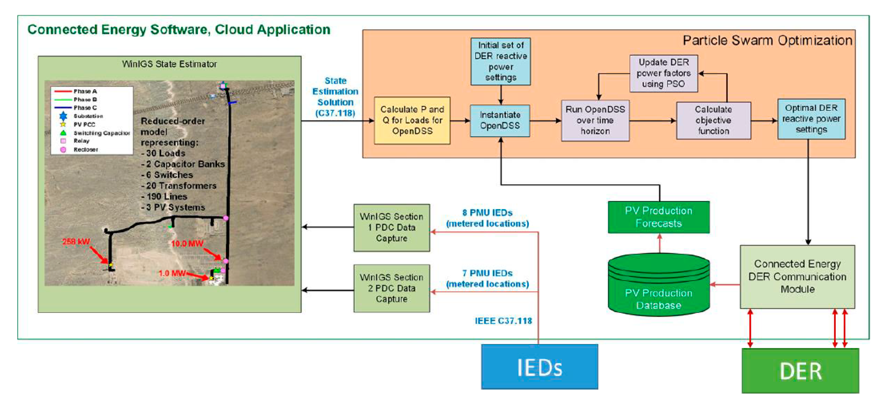
2.3. ProDROMOS
3. Evaluation Environments
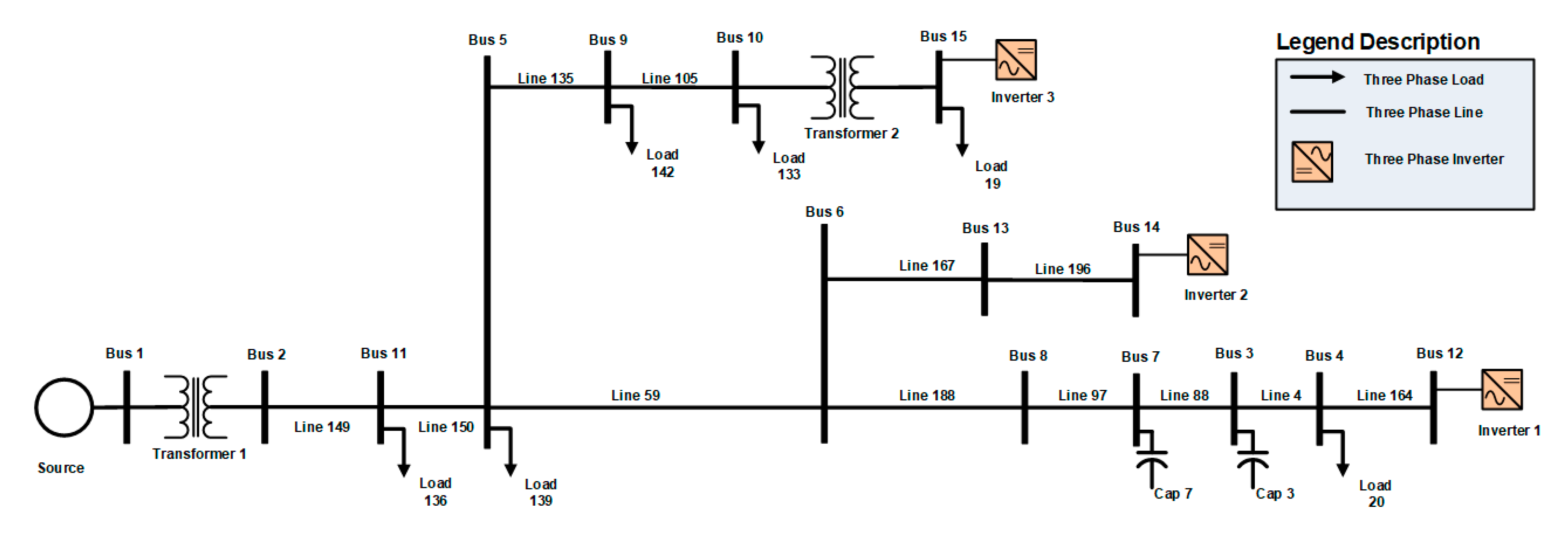
3.1. Distribution Systems of Study
3.2. Real-Time Evaluation Platform
4. Results for PNM Model
4.1. Simulations with the PNM Model
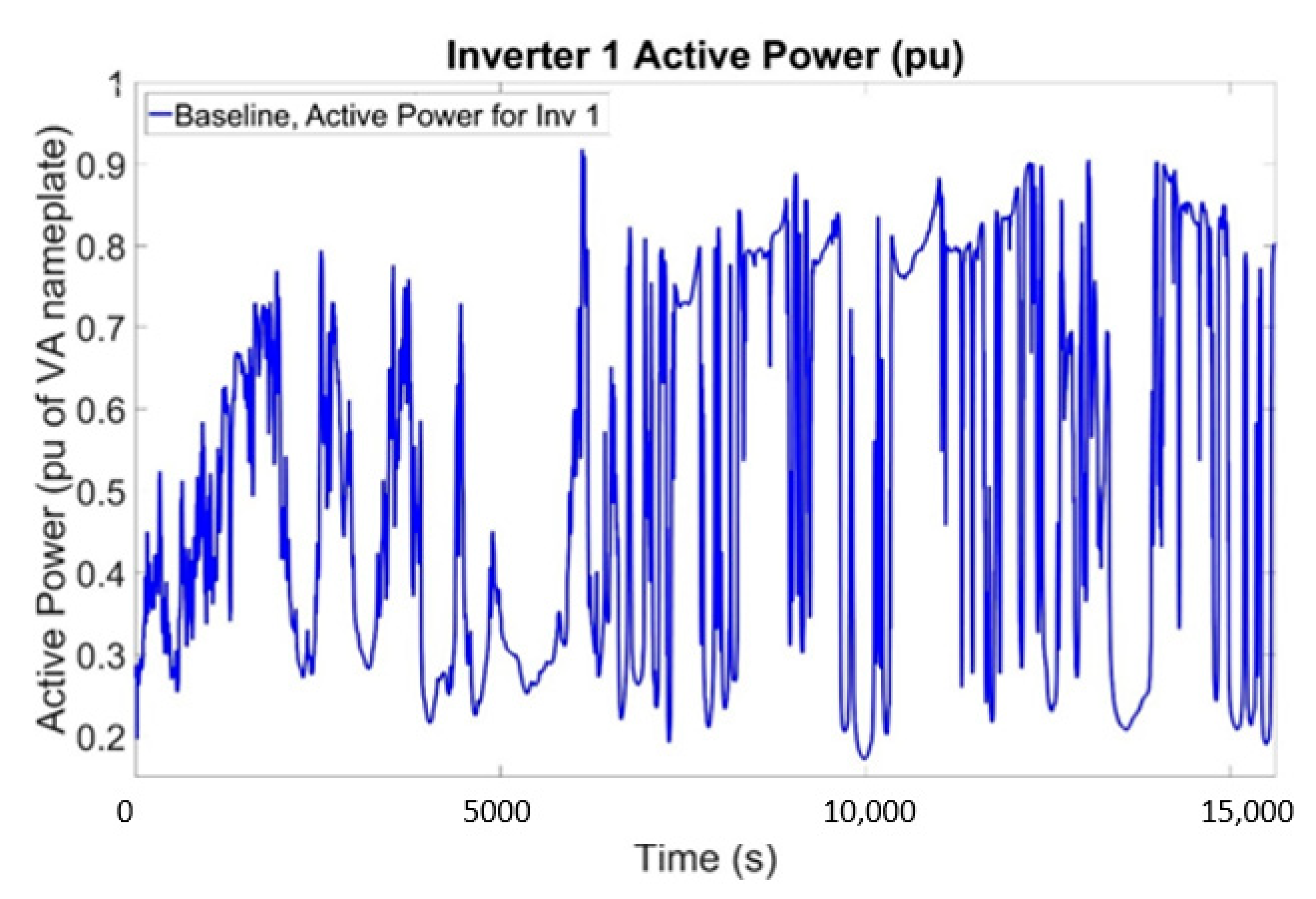
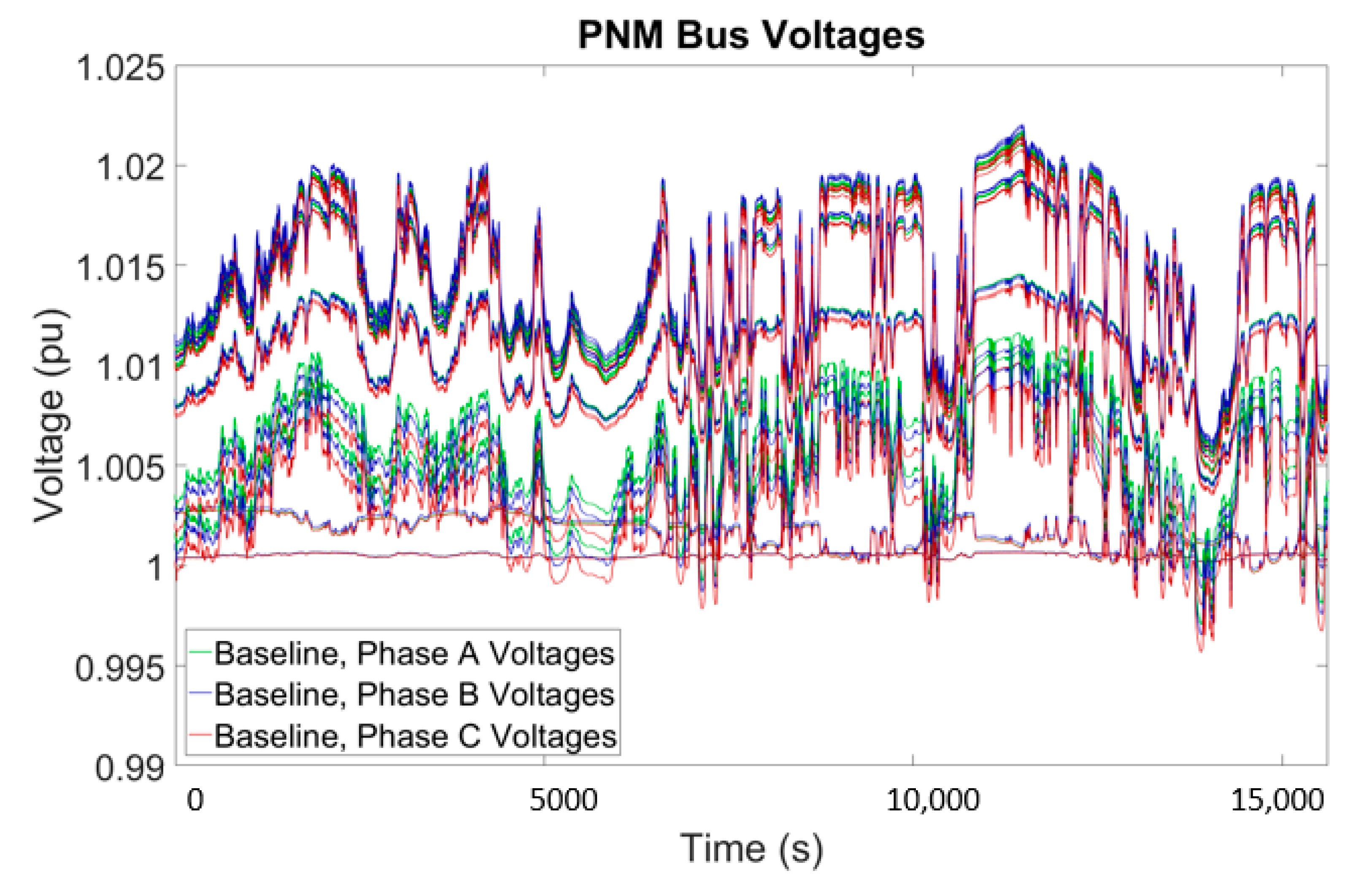
4.2. Baseline Simulation
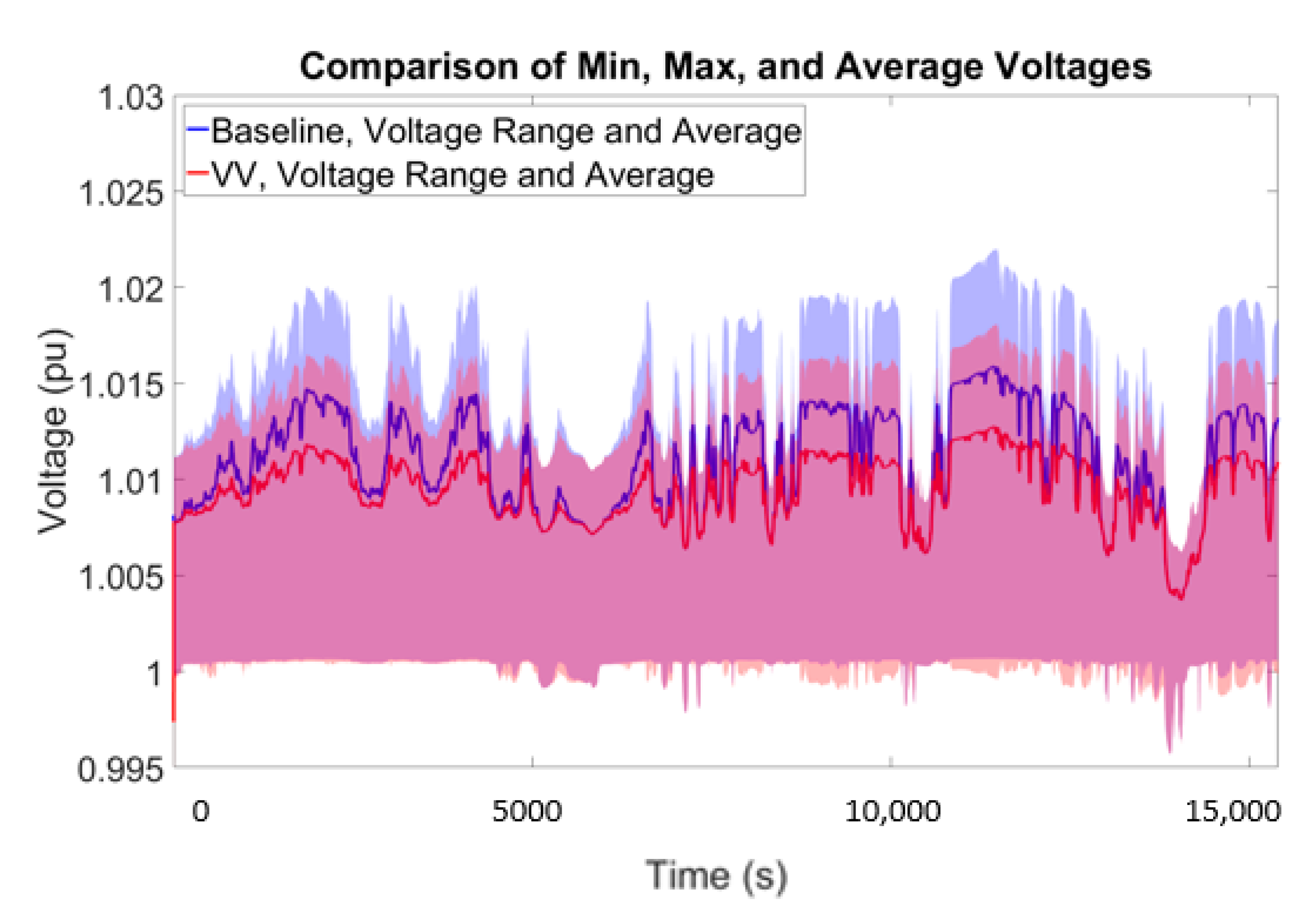
4.3. Volt–VAR Simulation
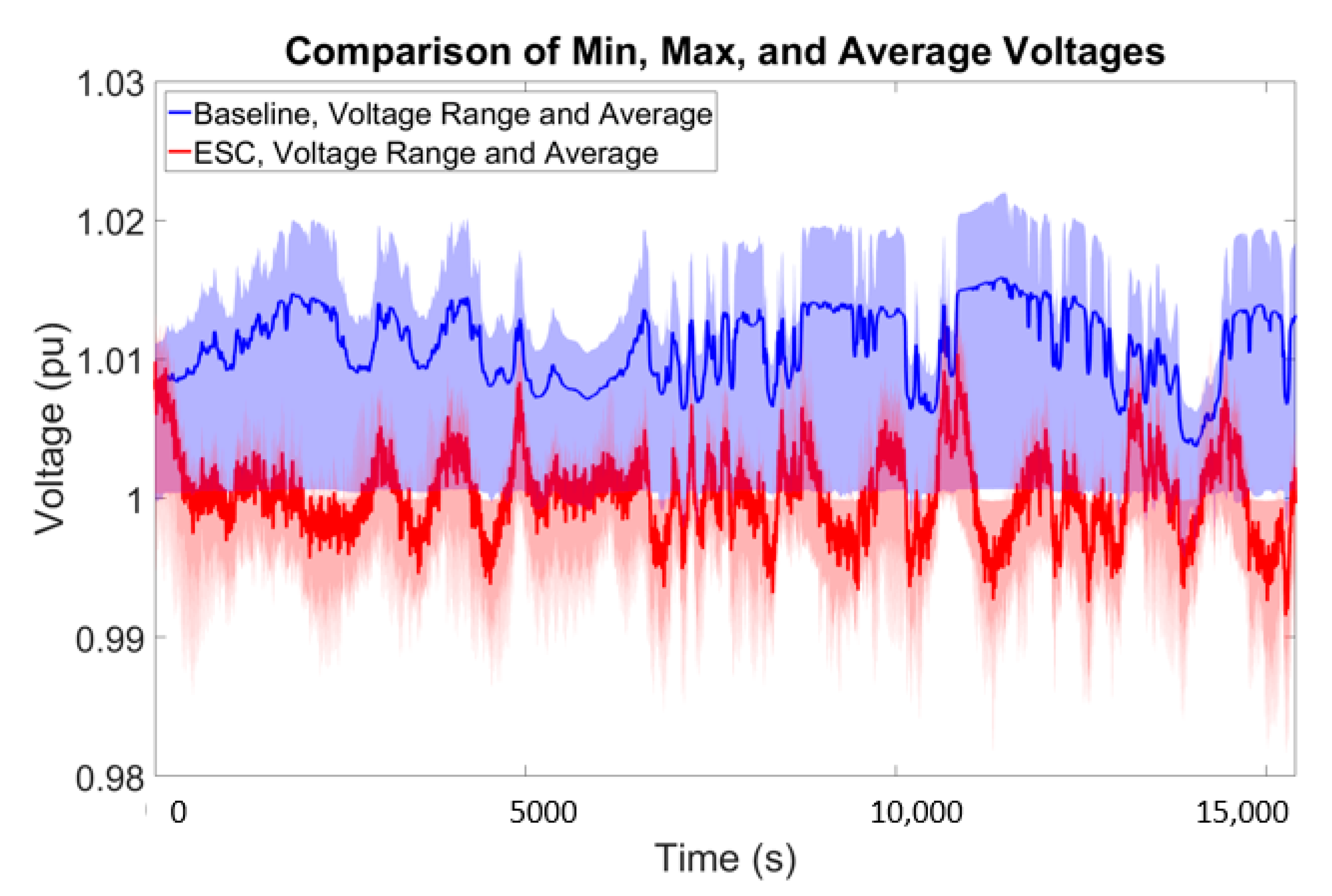
4.4. Extremum Seeking Control Simulation
4.5. State-Estimation-Based Particle Swarm Optimization
5. Results for National Grid Model
5.1. Simulations with the National Grid Model
5.2. Baseline Simulation with National Grid Model
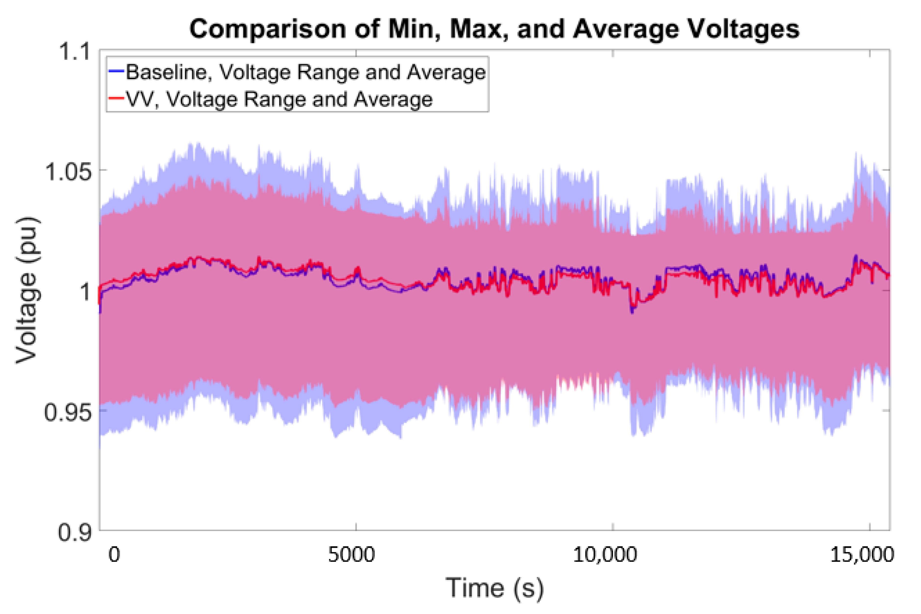
5.3. Volt–VAR
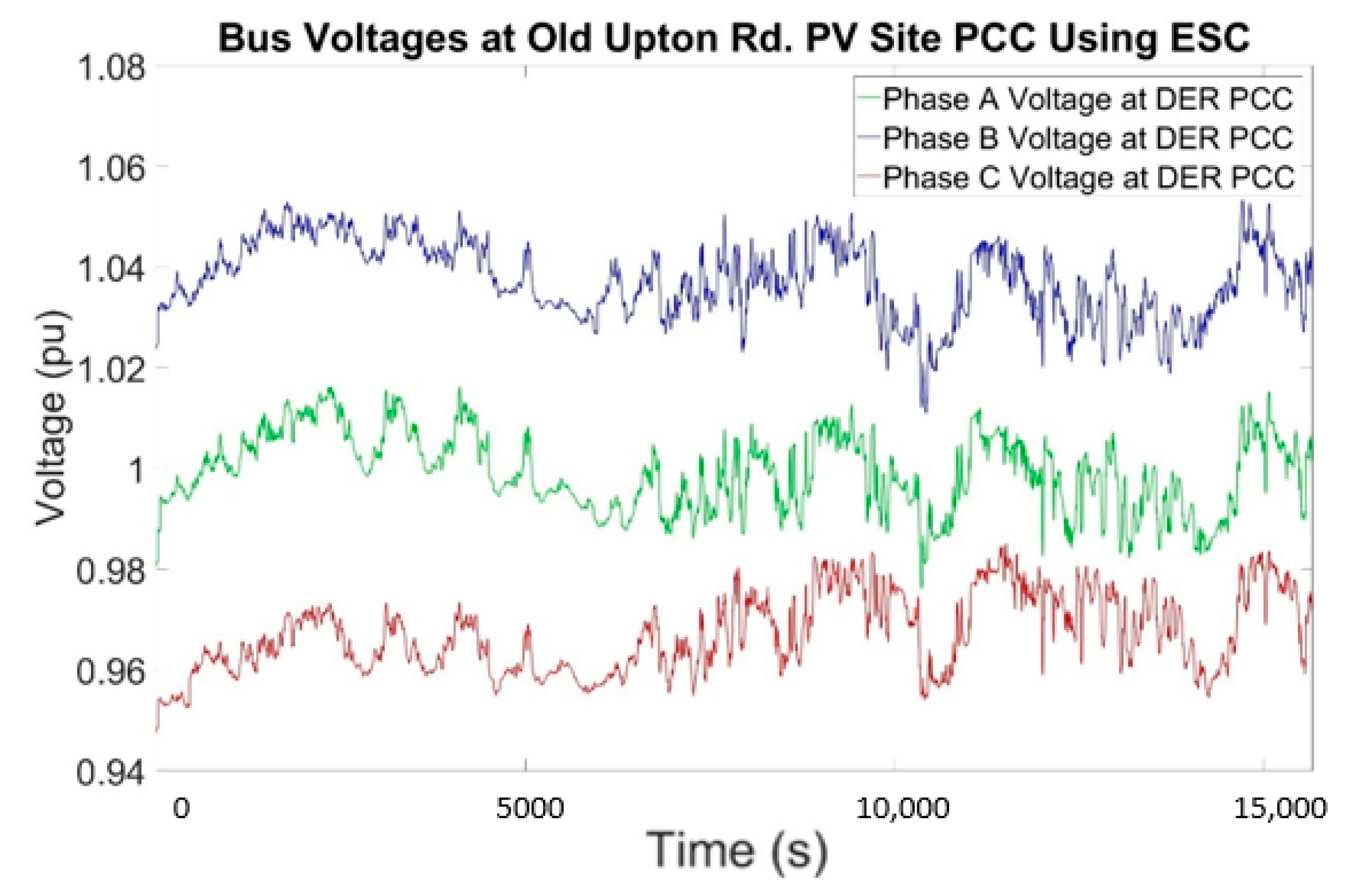
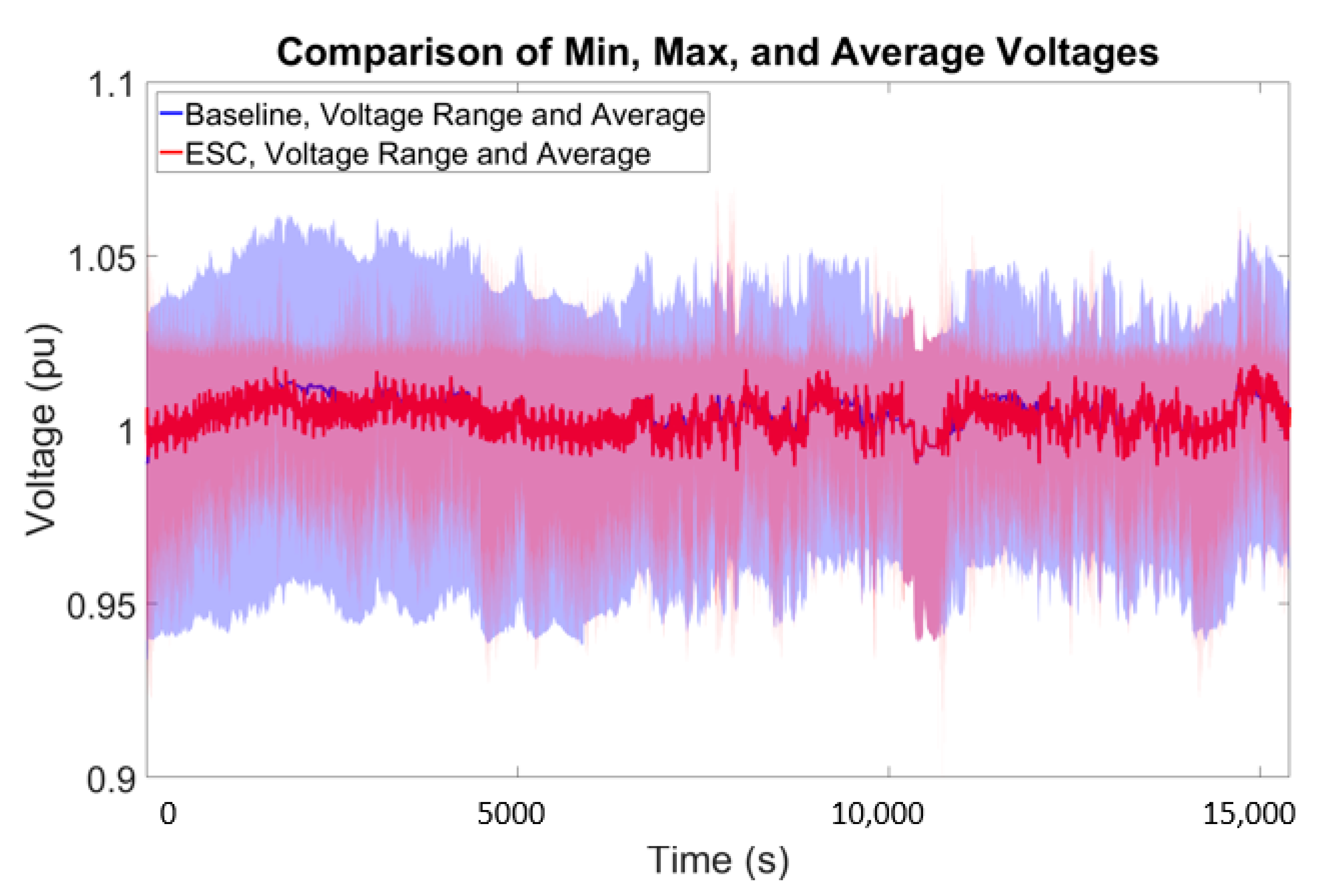
5.4. Extremum Seeking Control
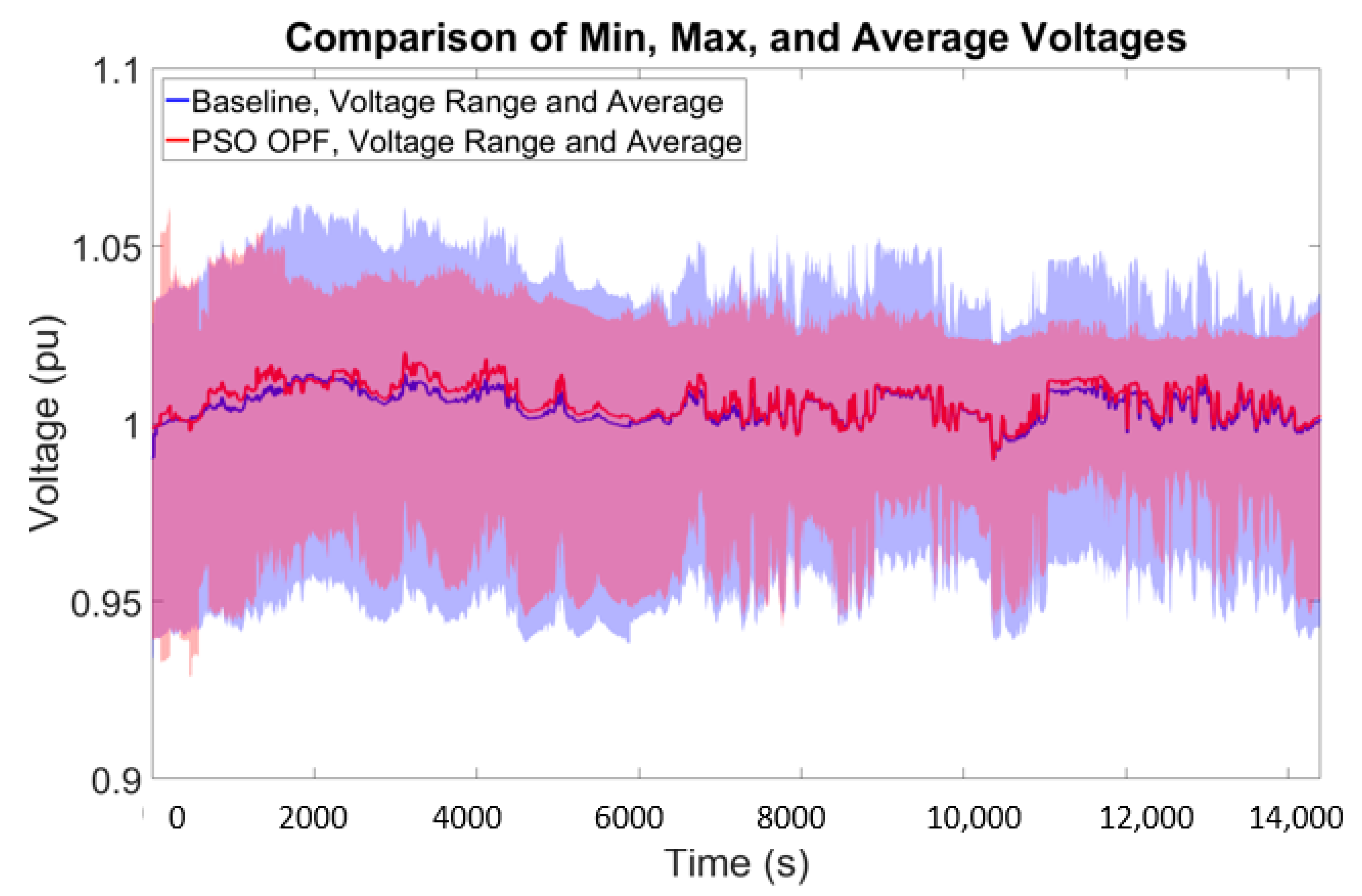
5.5. State-Estimation-Based Particle Swarm Optimization
6. PHIL Results
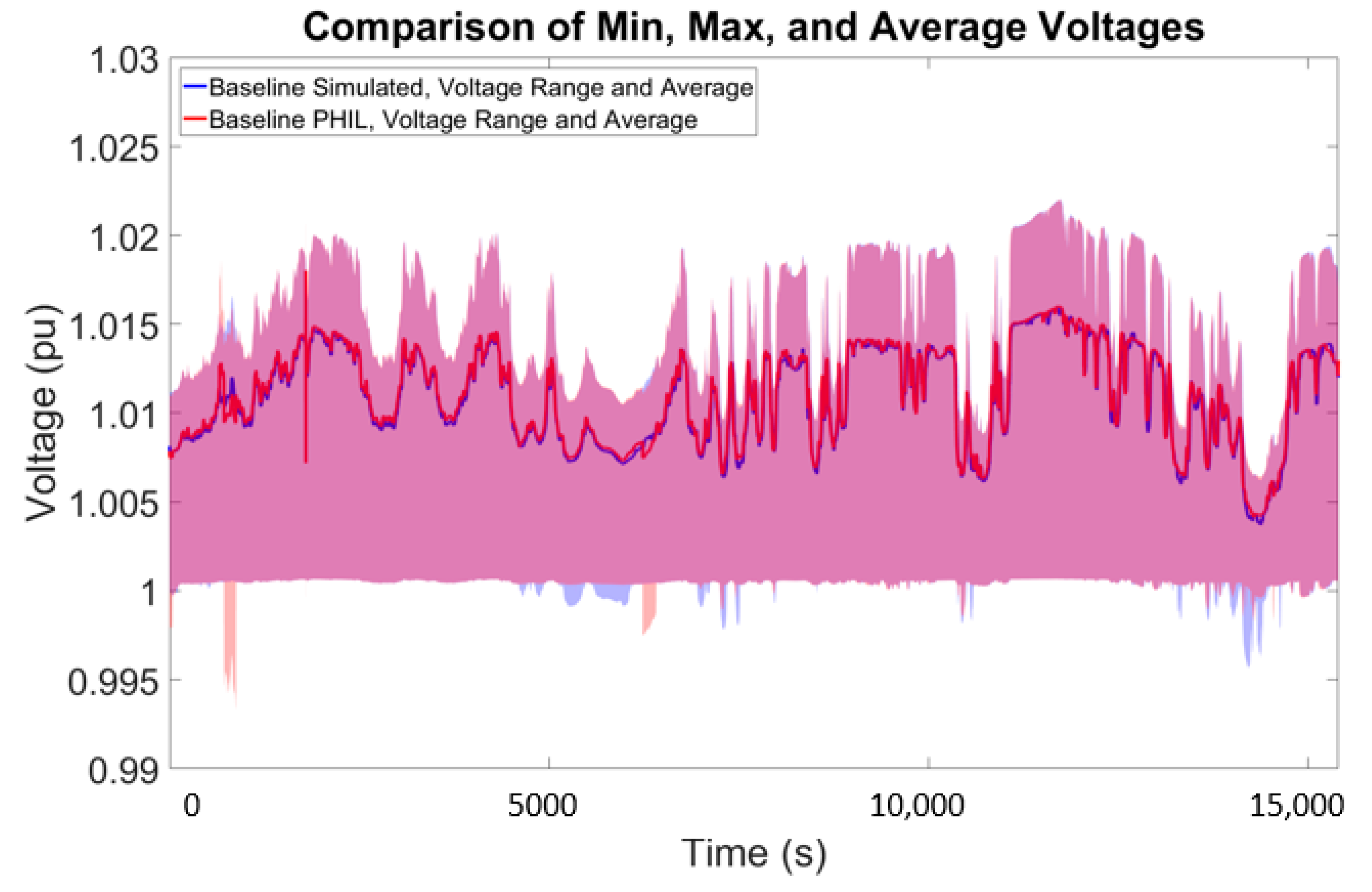
6.1. PNM Baseline
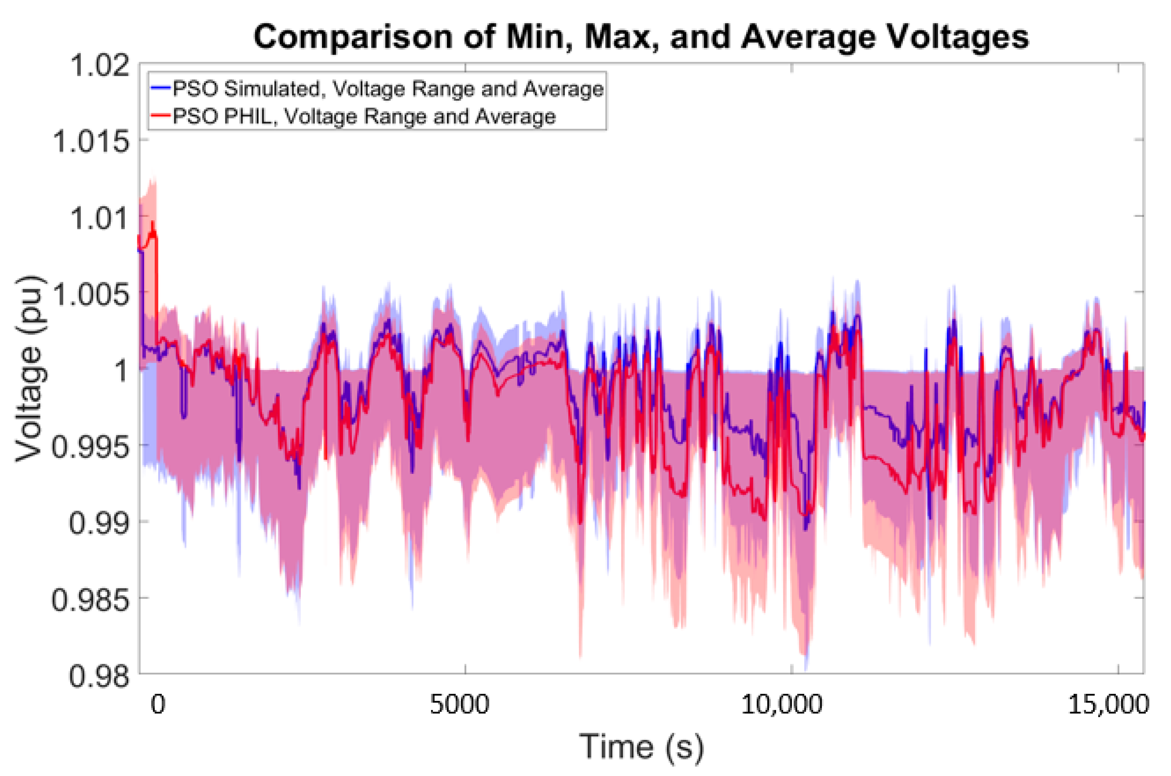
6.2. PNM Particle Swarm Optimixation PHIL
7. Discussion
8. Conclusions
9. Patents
Supplementary Materials
Author Contributions
Funding
Acknowledgments
Conflicts of Interest
Acronyms and Definitions
| Abbreviation | Definition |
| AC | Alternating Current |
| ANSI | American National Standards Institute |
| Dbus | Data Bus |
| DER | Distributed Energy Resource(s) |
| DERMS | Distributed Energy Resource Management System |
| DETL | Distributed Energy Technology Laboratory |
| DNP3 | Distributed Network Protocol 3 |
| DSO | Distribution System Operator |
| EPRI | Electric Power Research Institute |
| ESC | Extremum Seeking Control |
| GHI | Global Horizontal Irradiance |
| IED | Intelligent Electronic Device |
| IEEE | Institute of Electrical and Electronics Engineers |
| ITM | Ideal Transformer Method |
| LTC | Load Tap Changer |
| MA | Maine |
| NG | National Grid |
| NM | New Mexico |
| NREL | National Renewable Energy Laboratories |
| O&M | Operations and Maintenance |
| OLTC | On-Load Tap Changer |
| OPF | Optimal Power Flow |
| PCC | Point of Common Coupling |
| PF | Power Factor |
| PHIL | Power Hardware-in-the-Loop |
| PNM | Public Service Company of New Mexico |
| PRoDROMOS | Programmable Distribution Resource Open Management |
| PSO | Particle Swarm Optimization |
| PSO PF | Particle Swarm Optimization Optimal Power Factor |
| pu | Per unit |
| PV | Photovoltaic |
| RT | Real-Time |
| SANDIA | Sandia National Laboratories |
| SIL | Software in-the Loop |
| VV | Volt–VAR |
| WinIGS | Integrated Grounding System Analysis program for Windows |
References
- International Renewable Energy Agency. Future of Solar Photovoltaic: Deployment, Investment, Technology, Grid Integration and Socio-Economic Aspects (A Global Energy Transformation: Paper); International Renewable Energy Agency: Abu Dhab, UAE, 2019. [Google Scholar]
- National Electrical Manufactures Association. American National Standard for Electric Power Systems and Equipment-Voltage Rating (60 Hz); National Electrical Manufactures Association: Rosslyn, VA, USA, 2016. [Google Scholar]
- Denholm, P.; Clark, K.; O’Connell, M. On the Path to SunShot: Emerging Issues and Challenges in Integrating High Levels of Solar into the Electrical Generation and Transmission System; EERE Publication and Product Library: Washington, DC, USA, 2016.
- Sadeghian, H.; Wang, Z. Photovoltaic generation in distribution networks: Optimal vs. random installation. In Proceedings of the 2018 IEEE Power Energy Society Innovative Smart Grid Technologies Conference (ISGT), Washington, DC, USA, 19–22 February 2018; pp. 1–5. [Google Scholar] [CrossRef]
- Coddington, M.; Kroposki, B.; Mather, B.; Ellis, A.; Hill, R.; Lynn, K.; Razon, A.; Key, T.; Nicole, K.; Smith, J. Updating technical screens for PV interconnection. In Proceedings of the 2012 IEEE Photovoltaic Specialists Conference, Austin, TX, USA, 3–8 June 2012. [Google Scholar]
- Reno, M.J.; Broderick, R.J. Technical evaluation of the 15% of peak load PV interconnection screen. In Proceedings of the 2015 IEEE 42nd Photovoltaic Specialist Conference (PVSC), New Orleans, LA, USA, 14–19 June 2015; pp. 1–6. [Google Scholar]
- Rylander, M.; Broderick, R.J.; Reno, M.J.; Munoz-Ramos, K.; Quiroz, J.E.; Smith, J.; Rogers, L.; Dugan, R.; Mather, B.; Gotseff, P.; et al. Alternatives to the 15% Rule; Sandia Technical Report SAND2015-10099; Sandia National Laboratories: Albuquerque, NM, USA, 2015.
- Seguin, R.; Woyak, J.; Costyk, D.; Hambrick, J.; Mather, B. High-Penetration PV Integration Handbook for Distribution Engineers Technical Report; NREL/TP-5D00-63114; National Renewable Energy Lab: Golden, CO, USA, 2016.
- IEEE. IEEE Standard for Interconnection and Interoperability of Distributed Energy Resources with Associated Electric Power Systems Interfaces; IEEE Std 1547-2018; IEEE: Piscataway, NJ, USA, 2018. [Google Scholar]
- Seuss, J.; Reno, M.J.; Broderick, R.J.; Grijalva, S. Improving distribution network PV hosting capacity via smart inverter reactive power support. In Proceedings of the 2015 IEEE Power Energy Society General Meeting, Denver, CO, USA, 26–30 July 2015; pp. 1–5. [Google Scholar] [CrossRef]
- Farivar, M.; Neal, R.; Clarke, C.; Low, S. Optimal inverter VAR control in distribution systems with high PV penetration. In Proceedings of the 2012 IEEE Power and Energy Society General Meeting, San Diego, CA, USA, 22–26 July 2012; pp. 1–7. [Google Scholar] [CrossRef]
- Ding, F.; Mather, B.; Gotseff, P. Technologies to increase PV hosting capacity in distribution feeders. In Proceedings of the 2016 IEEE Power and Energy Society General Meeting (PESGM), Boston, MA, USA, 17–21 July 2016; pp. 1–5. [Google Scholar]
- Rylander, M.; Reno, M.J.; Quiroz, J.E.; Ding, F.; Li, H.; Broderick, R.J. Methods to determine recommended feeder-wide inverter settings for improving distribution performance. In Proceedings of the 2016 IEEE 43rd Photovoltaic Specialists Conference (PVSC), Portland, OR, USA, 5–10 June 2016; pp. 1393–1398. [Google Scholar] [CrossRef]
- Haghi, H.V.; Pecenak, Z.; Kleissl, J.; Peppanen, J.; Rylander, M.; Renjit, A.; Coley, S. Feeder impact assessment of smart inverter settings to support high PV penetration in California. In Proceedings of the 2019 IEEE Power & Energy Society General Meeting (PESGM), Atlanta, GA, USA, 4–8 August 2019; pp. 1–5. [Google Scholar] [CrossRef]
- Reno, M.J.; Lave, M.; Quiroz, J.E.; Broderick, R. PV ramp rate smoothing using energy storage to mitigate increased voltage regulator tapping. In Proceedings of the IEEE Photovoltaic Specialists Conference (PVSC), Portland, OR, USA, 5–10 May 2016. [Google Scholar]
- Georgilakis, P.S.; Hatziargyriou, N.D. Optimal distributed generation placement in power distribution networks: Models, methods, and future research. IEEE Trans. Power Syst. 2013, 28, 3420–3428. [Google Scholar] [CrossRef]
- Reno, M.J.; Broderick, R.J. Optimal siting of PV on the distribution system with smart inverters. In Proceedings of the 2018 IEEE 7th World Conference on Photovoltaic Energy Conversion (WCPEC) (A Joint Conference of 45th IEEE PVSC, 28th PVSEC & 34th EU PVSEC), Waikoloa Village, HI, USA, 10–15 June 2018; pp. 1468–1470. [Google Scholar]
- Antoniadou-Plytaria, K.E.; Kouveliotis-Lysikatos, I.N.; Georgilakis, P.S.; Hatziargyriou, N.D. Distributed and decentralized voltage control of smart distribution networks: Models, methods, and future research. IEEE Trans. Smart Grid 2017, 8, 2999–3008. [Google Scholar] [CrossRef]
- Primadianto, A.; Lu, C. A review on distribution system state estimation. IEEE Trans. Power Syst. 2017, 32, 3875–3883. [Google Scholar] [CrossRef]
- Dehghanpour, K.; Wang, Z.; Wang, J.; Yuan, Y.; Bu, F. A survey on state estimation techniques and challenges in smart distribution systems. IEEE Trans. Smart Grid 2019, 10, 2312–2322. [Google Scholar] [CrossRef]
- Elkhatib, M.E.; El-Shatshat, R.; Salama, M.M.A. Novel coordinated voltage control for smart distribution networks with DG. IEEE Trans. Smart Grid 2011, 2, 598–605. [Google Scholar] [CrossRef]
- Salih, S.N.; Chen, P. On coordinated control of OLTC and reactive power compensation for voltage regulation in distribution systems with wind power. IEEE Trans. Power Syst. 2016, 31, 4026–4035. [Google Scholar] [CrossRef]
- Xie, Q.; Hara, R.; Kita, H.; Tanaka, E. Coordinated control of OLTC and multi-CEMSs for overvoltage prevention in power distribution system. IEEJ Trans. Electr. Electron. Eng. 2017, 12, 692–701. [Google Scholar] [CrossRef]
- Zhu, X.; Zhang, Y. Coordinative voltage control strategy with multiple resources for distribution systems of high PV penetration. In Proceedings of the 2018 IEEE 7th World Conference on Photovoltaic Energy Conversion (WCPEC) (A Joint Conference of 45th IEEE PVSC, 28th PVSEC & 34th EU PVSEC), Waikoloa Village, HI, USA, 10–15 June 2018; pp. 1497–1502. [Google Scholar]
- Tonkoski, R.; Lopes, L.A.C.; El-Fouly, T.H.M. Coordinated active power curtailment of grid connected PV inverters for overvoltage prevention. IEEE Trans. Sustain. Energy 2011, 2, 139–147. [Google Scholar] [CrossRef]
- Johnson, J.; Summers, A.; Darbali-Zamora, R.; Hansen, C.; Reno, M.; Castillo, A.; Gonzalez, S.; Hernandez-Alvidrez, J.; Gurule, N.; Xie, B.; et al. Optimal Distribution System Voltage Regulation using State Estimation and DER Grid-Support Functions; Sandia Technical Report, SAND2020-2331; Sandia National Laboratories: Albuquerque, NM, USA, 2020.
- Meliopoulos, A.P.S. Windows Based Integrated Grounding System Design Program. Training Guide. 2017. Available online: http://www.ap-concepts.com/_downloads/IGS_TrainingGuide.pdf (accessed on 18 January 2017).
- Quiroz, J.E.; Reno, M.J.; Lavrova, O.; Byrne, R.H. Communication requirements for hierarchical control of volt-VAr function for steady-state voltage. In Proceedings of the 2017 IEEE Power & Energy Society Innovative Smart Grid Technologies Conference (ISGT), Washington, DC, USA, 23–26 April 2017; pp. 1–5. [Google Scholar] [CrossRef]
- Reno, M.J.; Quiroz, J.E.; Lavrova, O.; Byrne, R.H. Evaluation of communication requirements for voltage regulation control with advanced inverters. In Proceedings of the 2016 North American Power Symposium (NAPS), Denver, CO, USA, 18–20 September 2016; pp. 1–6. [Google Scholar]
- Xie, B.; Meliopoulos, A.P.S.; Zhong, C.; Liu, Y.; Sun, L.; Xie, J. Distributed quasi-dynamic state estimation incorporating distributed energy resources. In Proceedings of the 2018 North American Power Symposium (NAPS), Fargo, ND, USA, 9–11 September 2018. [Google Scholar]
- Choi, S.; Kim, B.; Cokkinides, G.J.; Meliopoulos, A.P.S. Feasibility study: Autonomous state estimation in distribution systems. IEEE Trans. Power Syst. 2011, 26, 2109–2117. [Google Scholar] [CrossRef]
- Xie, B.; Meliopoulos, A.P.S.; Liu, Y.; Sun, L. Distributed quasi-dynamic state estimation with both GPS-synchronized and non-synchronized data. In Proceedings of the 2017 North American Power Symposium (NAPS), Morgantown, WV, USA, 17–19 September 2017; pp. 1–6. [Google Scholar]
- Johnson, J.; Summers, A.; Darbali-Zamora, R.; Hernandez-Alvidrez, J.; Quiroz, J.; Arnold, D.; Anandan, J. Distribution voltage regulation using extremum seeking control with power hardware-in-the-loop. IEEE J. Photovolt. 2018, 8, 1824–1832. [Google Scholar] [CrossRef]
- Johnson, J.; Gonzalez, S.; Arnold, D.B. Experimental distribution circuit voltage regulation using DER power factor, volt-var, and extremum seeking control methods. In Proceedings of the 2017 IEEE 44th Photovoltaic Specialist Conference (PVSC), Washington, DC, USA, 25–30 June 2017; pp. 3002–3007. [Google Scholar] [CrossRef]
- Arnold, D.B.; Sankur, M.D.; Negrete-Pincetic, M.; Callaway, D.S. Model-free optimal coordination of distributed energy resources for provisioning transmission-level services. IEEE Trans. Power Syst. 2018, 33, 817–828. [Google Scholar] [CrossRef]
- Arnold, D.B.; Negrete-Pincetic, M.; Sankur, M.D.; Auslander, D.M.; Callaway, D.S. Model-free optimal control of VAR resources in distribution systems: An extremum seeking approach. IEEE Trans. Power Syst. 2016, 31, 3583–3593. [Google Scholar] [CrossRef]
- Distributed Energy Resources Connection Modeling and Reliability Considerations. 2017. Available online: http://www.nerc.com/comm/Other/essntlrlbltysrvcstskfrcDL/Distributed_Energy_Resource_Report.pdf. (accessed on 5 March 2020).
- Bründlinger, R. Grid codes in Europe for low and medium voltage. In Proceedings of the 6th International Conference on Integration of Renewable and Distributed Energy Resources, Kyoto, Japan, 17–20 November 2014. [Google Scholar]
- Reno, M.J.; Coogan, K.; Broderick, R.; Grijalva, S. Reduction of distribution feeders for simplified PV impact studies. In Proceedings of the 2013 IEEE 39th Photovoltaic Specialists Conference (PVSC), Tampa, FL, USA, 16–21 June 2013; pp. 2337–2342. [Google Scholar] [CrossRef]
- Pecenak, Z.K.; Disfani, V.R.; Reno, M.J.; Kleissl, J. Multiphase distribution feeder reduction. IEEE Trans. Power Syst. 2018, 33, 1320–1328. [Google Scholar] [CrossRef]
- EPRI. Overview of EPRI’s DER Simulation Tool for Emulating Smart Solar Inverters and Energy Storage Systems on Communication Networks: An Overview of EPRI’s Distributed Energy Resource Simulator; EPRI Report 3002009851; EPRI: Palo Alto, CA, USA, 2018. [Google Scholar]
- PV Performance Modeling Collaborative. Wavelet Variability Model. Available online: https://pvpmc.sandia.gov/applications/wavelet-variability-model/ (accessed on 5 March 2020).
- Lave, M.; Kleissl, J.; Stein, J.S. A wavelet-based variability model (WVM) for solar PV power plants. IEEE Trans. Sustain. Energy 2013, 4, 501–509. [Google Scholar] [CrossRef]
- Lave, M.; Kleissl, J.; Arias-Castro, E. High-frequency irradiance fluctuations and geographic smoothing. Sol. Energy 2012, 86, 2190–2199. [Google Scholar] [CrossRef]
- Lave, M.; Kleissl, J. Cloud speed impact on solar variability scaling—Application to the wavelet variability model. Sol. Energy 2013, 91, 11–21. [Google Scholar] [CrossRef]
- Lohmann, G.M. Irradiance variability quantification and small-scale averaging in space and time: A short review. Atmosphere 2018, 9, 264. [Google Scholar] [CrossRef]
- Bosch, J.L.; Zheng, Y.; Kleissl, J. Deriving cloud velocity from an array of solar radiation measurements. Sol. Energy 2013, 87, 196–203. [Google Scholar] [CrossRef]
- Summers, A.; Hernandez-Alvidrez, J.; Darbali-Zamora, R.; Reno, M.J.; Johnson, J.; Gurule, N.S. Comparison of ideal transformer method and damping impedance method for PV power-hardware-in-the-loop experiments. In Proceedings of the 2019 IEEE 46th Photovoltaic Specialists Conference (PVSC), Chicago, IL, USA, 16–21 June 2019; pp. 2989–2996. [Google Scholar] [CrossRef]
- Hernandez-Alvidrez, J.; Summers, A.; Pragallapati, N.; Reno, M.J.; Ranade, S.; Johnson, J.; Brahma, S.; Quiroz, J. PV-inverter dynamic model validation and comparison under fault scenarios using a power hardware-in-the-loop testbed. In Proceedings of the 2018 IEEE 7th World Conference on Photovoltaic Energy Conversion (WCPEC) (A Joint Conference of 45th IEEE PVSC, 28th PVSEC & 34th EU PVSEC), Waikoloa Village, HI, USA, 10–15 June 2018; pp. 1412–1417. [Google Scholar]
- Holmgren, W.F.; Hansen, C.W.; Mikofski, M.A. pvlib python: A python package for modeling solar energy systems. J. Open Source Softw. 2018, 3, 884. [Google Scholar] [CrossRef]


| J Function | l | h | rcomm | Inverter 1 (258 kW) | Inverter 2 (10 MW) | Inverter 3 (1 MW) | |||||||||
|---|---|---|---|---|---|---|---|---|---|---|---|---|---|---|---|
| P | f | a | k | P | f | a | k | P | f | a | k | ||||
| 2 s | 258 kW | 51.6 kVar | −2.58 × 10⁷ | 10 MW | 50 kVar | −1 × 10⁹ | 1 MW | 50 kVar | −1 × 10⁸ | ||||||
| J function | l | h | rcomm | Three-Phase Inverter | Inverters on Phase A | Inverters on Phase B | Inverters on Phase C | ||||||||
|---|---|---|---|---|---|---|---|---|---|---|---|---|---|---|---|
| f | a | k | f | a | k | f | a | k | f | a | k | ||||
| 2 s | |||||||||||||||
| PNM Feeder Score | |||||
|---|---|---|---|---|---|
| Phase A (×1000) | Phase B (×1000) | Phase C (×1000) | Average (×1000) | Average Impact (%) | |
| VV | 0.467 | 0.468 | 0.466 | 1.401 | 12.9% |
| ESC | 2.745 | 2.748 | 2.591 | 8.084 | 74.5% |
| PSO | 2.727 | 2.731 | 2.541 | 7.999 | 73.7% |
| Best Score | 3.650 | 3.681 | 3.519 | 10.850 | |
| NG Feeder Score Controlling All PV | |||||
|---|---|---|---|---|---|
| Phase A (×1000) | Phase B (×1000) | Phase C (×1000) | Average (×1000) | Average Impact (%) | |
| VV | −0.058 | 1.855 | 1.281 | 3.078 | 15.2% |
| ESC | −0.345 | 4.971 | 3.068 | 7.694 | 38.0% |
| PSO | −0.345 | 1.878 | 2.079 | 3.612 | 17.8% |
| Best Score | 2.937 | 9.624 | 7.678 | 20.238 | |
© 2020 by the authors. Licensee MDPI, Basel, Switzerland. This article is an open access article distributed under the terms and conditions of the Creative Commons Attribution (CC BY) license (http://creativecommons.org/licenses/by/4.0/).
Share and Cite
Summers, A.; Johnson, J.; Darbali-Zamora, R.; Hansen, C.; Anandan, J.; Showalter, C. A Comparison of DER Voltage Regulation Technologies Using Real-Time Simulations. Energies 2020, 13, 3562. https://doi.org/10.3390/en13143562
Summers A, Johnson J, Darbali-Zamora R, Hansen C, Anandan J, Showalter C. A Comparison of DER Voltage Regulation Technologies Using Real-Time Simulations. Energies. 2020; 13(14):3562. https://doi.org/10.3390/en13143562
Chicago/Turabian StyleSummers, Adam, Jay Johnson, Rachid Darbali-Zamora, Clifford Hansen, Jithendar Anandan, and Chad Showalter. 2020. "A Comparison of DER Voltage Regulation Technologies Using Real-Time Simulations" Energies 13, no. 14: 3562. https://doi.org/10.3390/en13143562
APA StyleSummers, A., Johnson, J., Darbali-Zamora, R., Hansen, C., Anandan, J., & Showalter, C. (2020). A Comparison of DER Voltage Regulation Technologies Using Real-Time Simulations. Energies, 13(14), 3562. https://doi.org/10.3390/en13143562