Article

Decreasing Mining Losses for the Room and Pillar Method by Replacing the Inter-Room Pillars by the Construction of Wooden Cribs Filled with Waste Rocks

by
Krzysztof Skrzypkowski
Faculty of Mining and Geoengineering, AGH University of Science and Technology, Mickiewicza 30 av., 30-059 Cracow, Poland
Energies 2020, 13(14), 3564; https://doi.org/10.3390/en13143564
Submission received: 16 June 2020 / Revised: 3 July 2020 / Accepted: 7 July 2020 / Published: 10 July 2020

Abstract

:
The article presents methods of securing mining excavations using wooden cribs. For the underground room and pillar method used to excavate zinc and lead ore body in the Olkusz-Pomorzany mine in Poland, model tests for the replacement of rock pillars by wooden cribs are presented. In the first stage of research, the results of laboratory strength tests carried out on models of four-point, six-point and eight-point cribs made of wooden beech beams at a 1:28 scale arranged horizontally were determined. For the first time, a concave round notch connection was used to connect the beams of the wooden cribs. The maximal capacity of cribs consisting only of beams and filled with waste rocks taken from underground mining excavations was determined. In addition, the vertical deformations of the cribs at maximal loading force and their specific deformations are presented. Additionally, on the basis of load-displacement characteristics, the range in variability of the stiffness of empty cribs and those filled with waste rocks was calculated as a function of their compressibility. In the second stage of research, the room and pillar method was designed in the Phase2 numerical program. The aim of the study was to determine the stresses in the inter-room pillars. Based on the results of laboratory and numerical tests, a factor of safety was determined, indicating that it is possible to reduce mining losses while maintaining the safe exploitation conditions of the ore body.

Graphical Abstract

1. Introduction

The rational management of mineral resources is aimed at combining the efficiency of their extraction, their comprehensive and rational use, and minimizing damage to the human environment. The use of resources is shaped at all stages of geological and mining activity, from the exploration and documentation of deposits, through the design, exploitation and processing of minerals. The main factors affecting the use of resources are, among others, the classification of resources, and mining losses and dilution of the deposit. In underground mining, new support systems are still being sought, whose main task is, among others, to reduce mining losses, while maintaining a high level of safety for the works being carried out. In room and pillar methods, attempts are made to strengthen the excavations or replace the inter-room pillars by wooden or concrete constructions. Barczak and Tastillo [1], Korzeniowski and Skrzypkowski [2], and Korzeniowski et al. [3] studied wooden cribs with beams of rectangular and square section. Daehnke et al. [4], Dison and Smith [5], and Mining Product Developments [6] determined the strength parameters for grout bags in conjunction with timber pack. Skrzypkowski [7] and Strata Worldwide Company [8] determined the load-displacement characteristics for groups of wooden props. Kushwaha et al. [9] tested a steel cog. Strata Worldwide Company [8] proposed to secure excavations in the form of sand props. Li et al. [10] designed an expandable pillar, which uses a chemical mixture that expands when water is introduced. Luan et al. [11] created and tested a lightweight and high-strength foam concrete and a mortise-and-tenon structure hollow-block wall. Hadjigeorgiou et al. [12], Kang et al. [13], and Cao et al. [14] proposed to replace rock pillars by artificial pillars based on cement binder. Despite the significant technical progress that has been made in recent years, wood is still used to support underground excavations, especially mining ones. Wooden crib support is commonly used to strengthen underground mine roadway and room excavations. Cribs that are full, openwork, empty, or filled by cement binder or waste rocks are used. The wooden cribs used in underground mining are built of old railway sleepers, round wood or properly prepared rectangular or cylindrical wooden beams. The capacity of the crib support depends, among others, on the geometry and the number of contact points joining individual cribs, the type of wood used, the type of cut jams, and the method of filling the empty space [4]. For example, a cubic crib made of pine wood 1.5 m long filled by waste rocks has a capacity of 6.75 MN at 25% compressibility and 13.50 MN at 50% compressibility. However, for oak with the same configuration, the support is 11.25 MN at 25% compressibility and 45 MN at 50% compressibility [15]. Tests on the connection configuration of four-point, nine-point and full contact beams have shown that the magnitude of elastic and plastic stiffness depends on the contact area of the beams and height. Stiffness increases linearly with the contact surface and increases exponentially as the height decreases [1]. The capacity of the wooden crib increases with increasing convergence. For example, cribs 1.6 m × 1.1 m with a height of 1.45 m, made of round timber from pine wood, have an average capacity of: 140 kN with a compressibility of 10%; 220 kN at a compressibility of 20%; and 270 kN at 30% compressibility [16]. In underground hard coal mines, wooden cribs are an alternative to the possible costly necessity of driving another roadway. Wooden cribs are used to maintain roadways, which means that there is no need to make another roadway for the next longwall. The same roadway has a transport function for the first longwall and a ventilation function for the second longwall (Figure 1a,b).
In underground ore mining, rock bolt support is the basic way to support excavations [17,18]. Often, however, the rock bolt support is additionally strengthened by means of a wooden support in the form of individual props or rows of props as well as by means of wooden cribs. The primary task of the wooden support is the fencing and strengthening of places threatened with a roof fall [19]. In a room and pillar method with roof sag in copper ore mining in the Legnicko-Głogów Copper District in Poland, wooden cribs are used during the last-phase liquidation of post-mining spaces. Wooden cribs are built between residual pillars (Figure 2a,b). The cribs built in the middle of the excavation constitute an element that strengthens the rock bolt support and at the same time act as an element separating access to the section endangered by the roof fall. In zinc and lead ore mining in the Olkusz region in Poland, the cribs next to the side walls, mainly in the corners of the widened crossings, constitute a support reducing the width of the excavation roof (Figure 2c–e).
In this article laboratory compressive tests on wooden cribs models are presented. Additionally, the maximal loads and vertical and specific deformations for empty cribs and those filled with waste rocks were determined. Furthermore, on the basis of load-displacement characteristics, the ranges of variability of the stiffness of empty and filled cribs with waste rocks were calculated as a function of their compressibility. Furthermore, in this study, the room and pillar method was designed in the Phase2 numerical program. The aim of the study was to determine the stresses in the inter-room pillars. Based on the results of laboratory and numerical tests, a factor of safety was determined.

2. Sources of the Mining Losses in the Room and Pillar Method for Lead and Zinc Ore Deposit

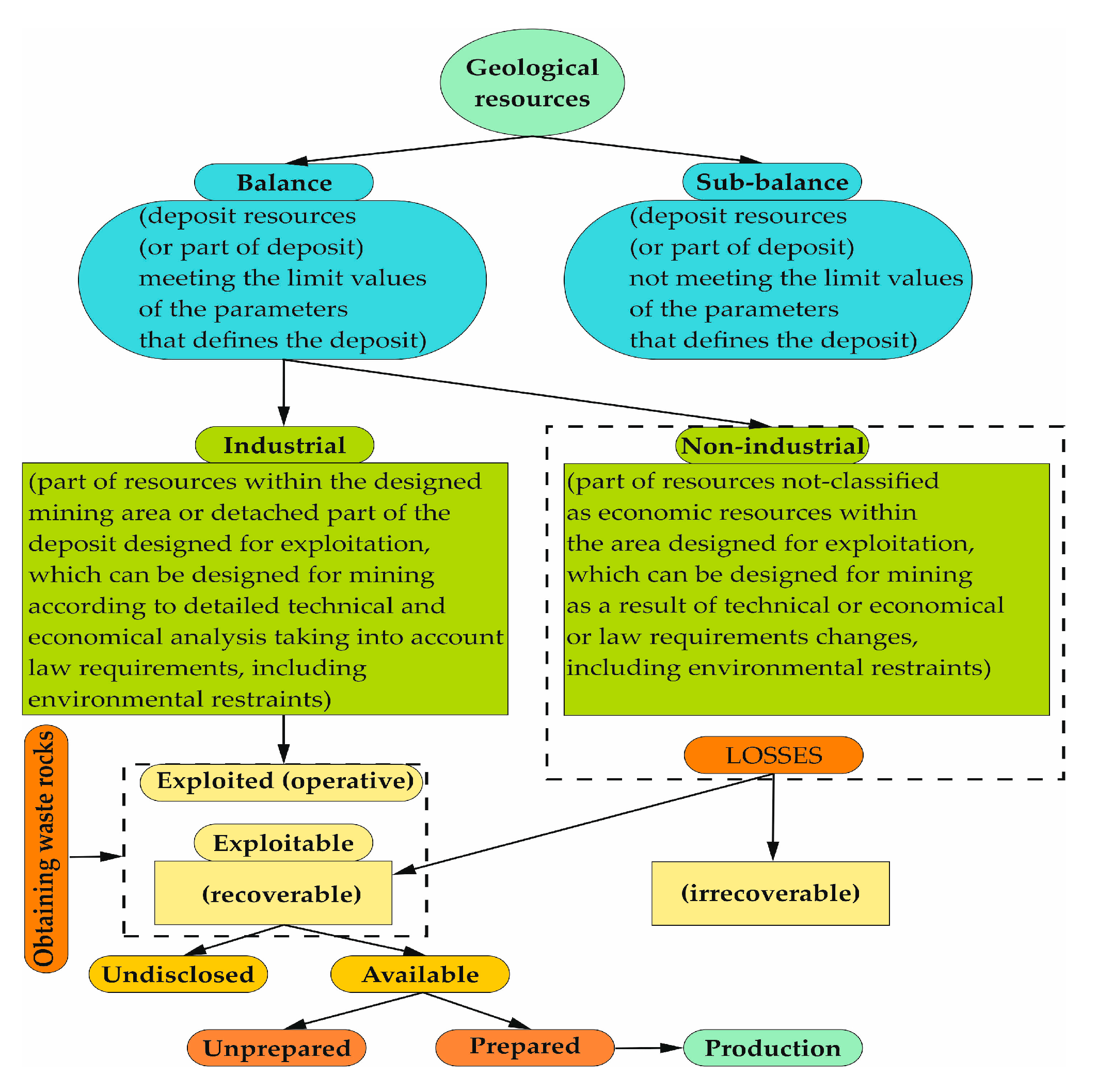
Due to the complete recognition of the deposit, geological resources are divided into balance and sub-balance. Exploitation losses that can be recovered can be divided into hidden and available ones, which in turn can be divided into those prepared and unprepared for exploitation (Figure 3). Geological resources are those that meet the limits for the values of the parameters defining the deposit, according to Polish regulations [20,21]. For example, the minimum content of zinc and lead for Polish deposits of zinc and lead appearing in sulfide form in a sample contouring the deposit, regardless of the degree of oxidation of the ore, should be at least 2%.
The production capacity of the mining plant and its lifetime are determined during the design of mining branches by reducing industrial resources by the losses expected in the adopted deposit exploitation system and in the adopted mineral processing processes. Mining losses or, strictly, the resources lost during exploitation are part of the balance of resources not extracted from the deposit. The following factors affect the amount of losses:
  • geological factors (arising as a result of deposit disruption by discharges, elevations, or fissures, as well as losses resulting from the complicated form of the deposit: exclusion, irregularities in a deposit occurring);
  • hydrogeological factors (losses related to leaving protective pillars, preventing the ingress of water or the inability to select a deposit due to water accumulation);
  • leaving the deposit in pillars to protect capital excavations, surface structures, canals, rivers, roads, and other objects that are within the impact of mining works (pillars left between exploitation fields or individual excavations, to avoid mutual interaction; losses in protective pillars, and also in pillars left to support the roof in a room methods);
  • leaving part of the deposit as a result of changing deposit parameters;
  • the method of transporting the excavated material underground (losses occur as a result of spilling the excavated material while loading it onto carts or conveyors);
  • losses in non-industrial resources as a result of mining being removed by mining works;
  • loosening of the mineral in the filling, during layer exploitation, as well as ore discharge.
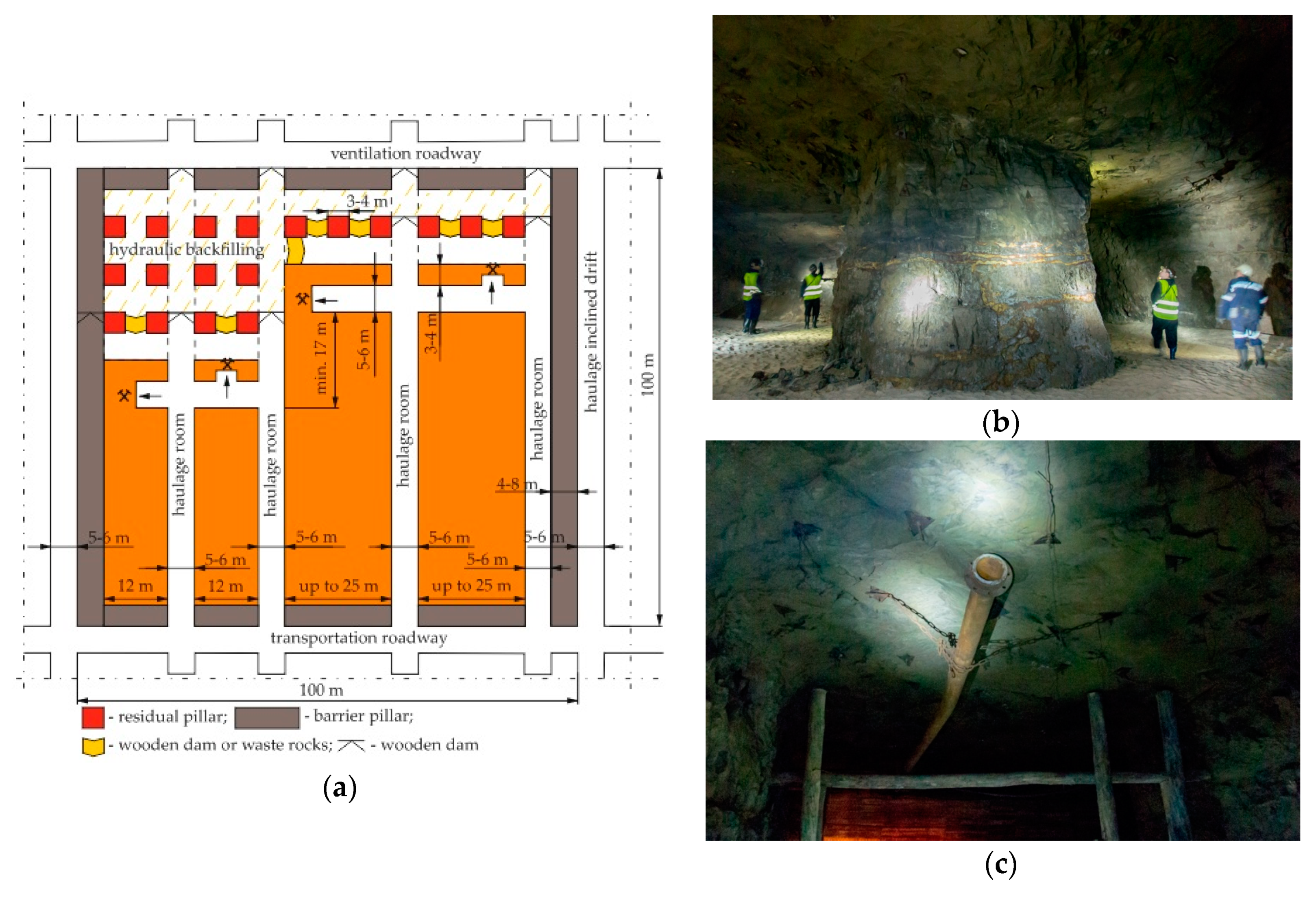
In the Olkusz-Pomorzany mine in Poland, the exploration drift grid is 100 m × 100 m, so exploitation fields of 1 hectare are separated. The exploitation field is divided into smaller fields with a width of 12 to 25 m by means of haulage rooms (Figure 4a). Smaller fields are mined by means of rooms with a width of 5 to 6 m. Rooms are mined parallel to the front line, leaving a continuous inter-room pillar with a width of 3 to 4 m. In order to minimize mining losses, the inter-room pillar is selected partly with the help of rooms driven towards goafs. This creates square pillars with a side length of 3 to 4 m (Figure 4b). After the cutting of continuous pillars, the post-mining void is filled. Hydraulic sand backfilling includes a number of pillars and exploitation rooms from the goaf side. On the line of the penultimate row of pillars, wooden dams are built in the cutting room. Instead of filling the dams, it is possible to make a heap from waste rocks obtained from the workings. A filling pipeline is fed through one of the filling dams (Figure 4c), which is shortened as goafs are filled.

3. Laboratory Tests on the Mining Crib Models

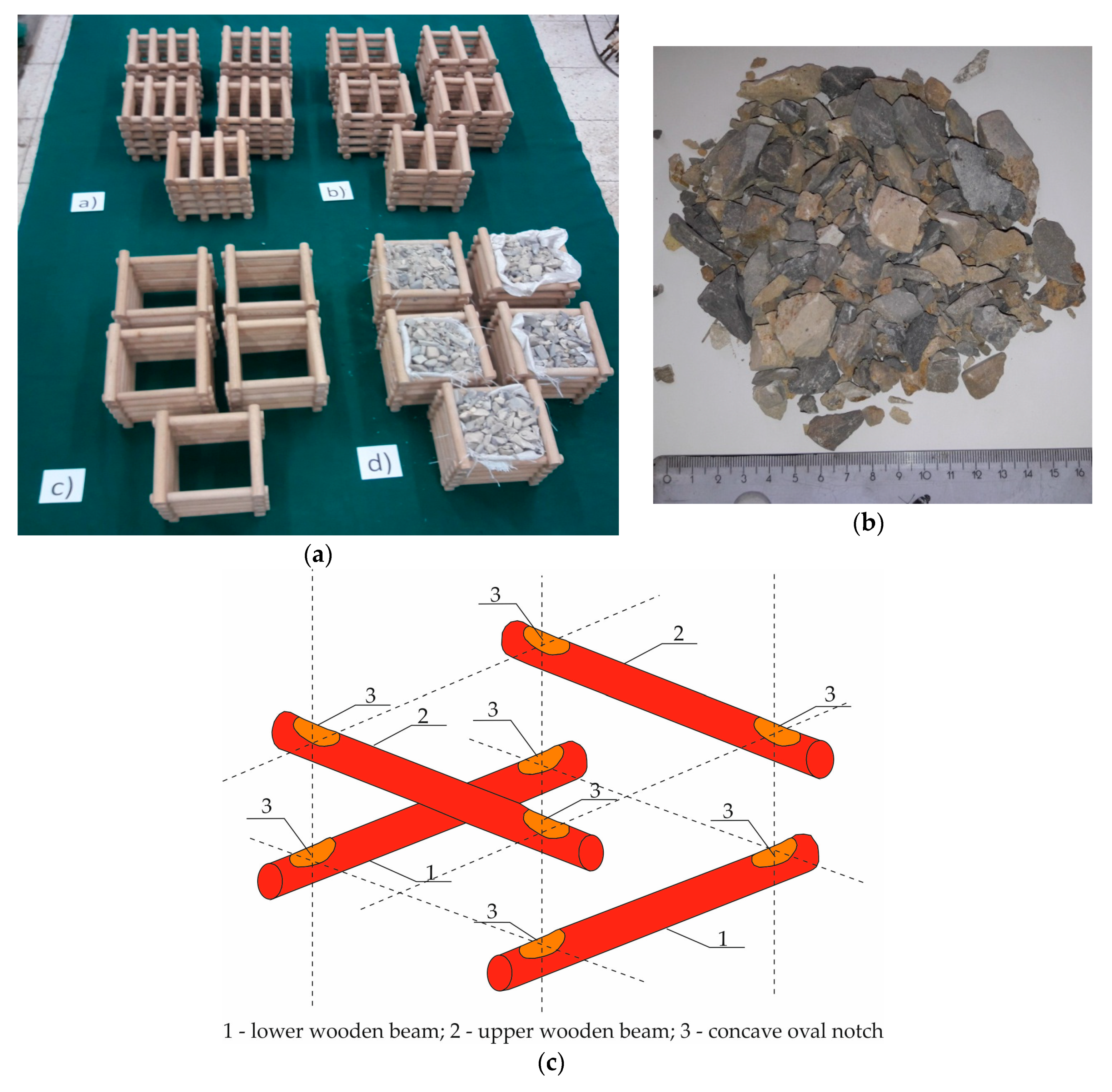
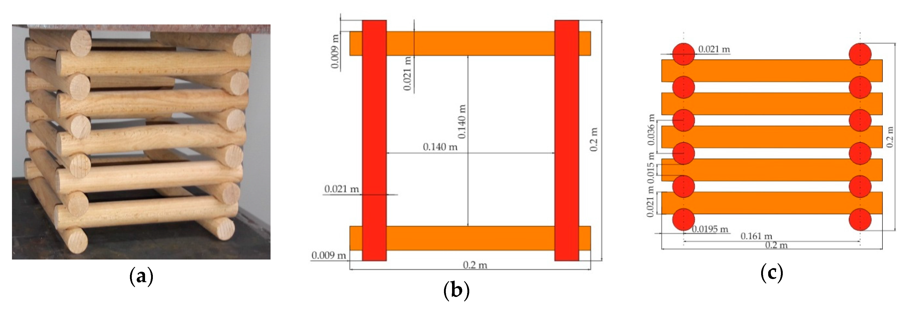
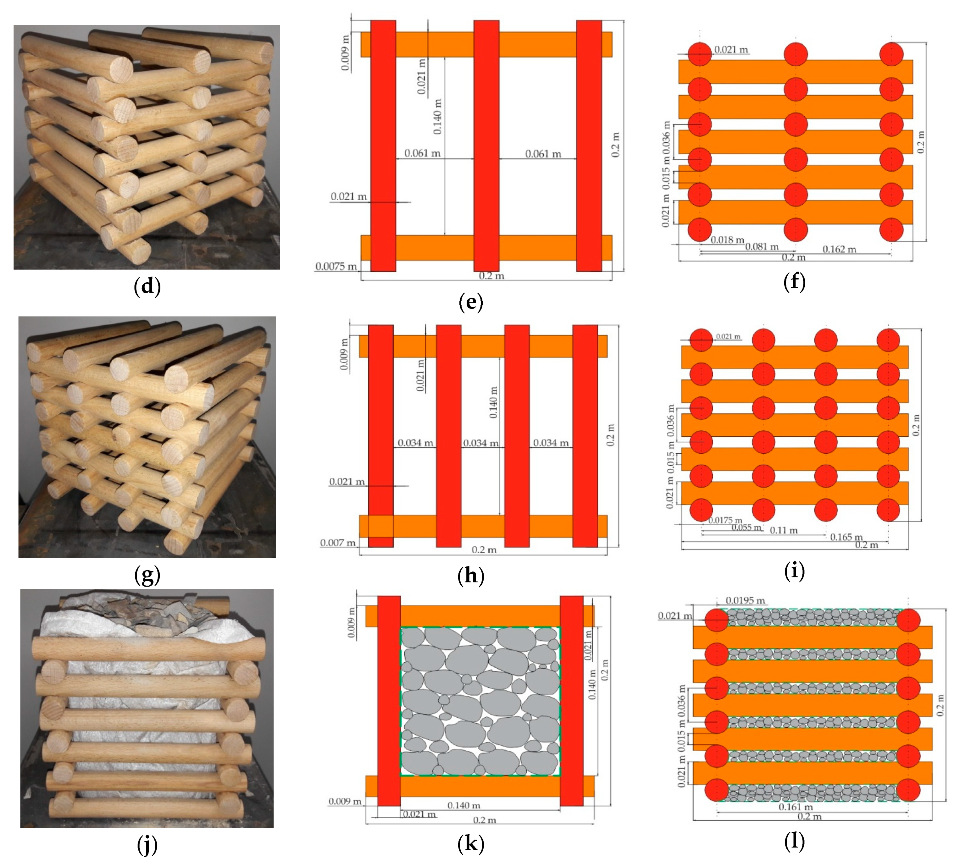
The subject of the laboratory tests were models of mining cribs made of beech wooden beams with a circular cross-section, currently used in many underground mines (Figure 5a). The wood used had an absolute humidity of 8%. Models of the cribs were made on a 1:28 geometric scale. The main reason for using such a scale was to best match the crushed waste rocks to the interior of the wooden cribs. The fit consisted of a tight adherence of the crushed rock, with as little free space as possible between the rocks. If a larger scale was used, the free spaces between the rocks would be larger due to the diameter of the lumps, which in the conditions of the Olkusz-Pomorzany mine ranges from 0.1 m to 0.5 m. Beams measuring 0.021 m × 0.2 m were used to build models of cribs. Four-point, six-point, and eight-point models of cribs without filling were constructed from 22, 28, and 34 beams, respectively (Figure 6a–i). For the first time, the beams were connected by concave round notches (Figure 5c). The mining wooden crib was made of longitudinal round beams arranged on top of each other in horizontal layers, with the beams of adjacent layers crossing and leaning on each other in concave notches, creating a structure in the shape of a straight prism or a set of straight prisms, with each layer containing at least two beams, characterized in that the notches are found only in the upper parts of the beams of each layer, except for the roof beams, which do not have notches [22]. This is a very advantageous solution, because only wood is used to connect wooden beams, without the use of steel clamps. In order for the beams to be connected and not move in each beam, concave oval notches were made with a depth of 0.003 m. In addition, the four-point cribs were filled with waste rocks (Figure 6j–l). In the Olkusz-Pomorzany zinc and lead mine, the deposits occur in the form of irregular nests and lenses. Exploratory excavations are carried out at a distance of 100 m. Rock lumps (dolomitic limestone) were taken from exploratory drifts where the useful mineral content was below 2%. Regardless of the percentage of useful minerals, all rocks were transported to the discharge grate and then transported to the processing plant. In laboratory conditions, the rock lumps (dolomitic limestone) were ground in a jaw crusher to a particle size of 0.005 to 0.018 m (Figure 5b). The compressive strength of dolomitic limestone was 30 MPa [23]. The inner mesh of the crib was polypropylene canvas commonly used for the construction of filling dams in underground mining. The height of each model was 0.2 m.
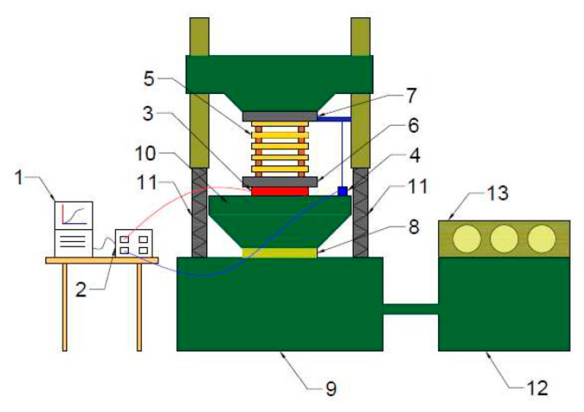
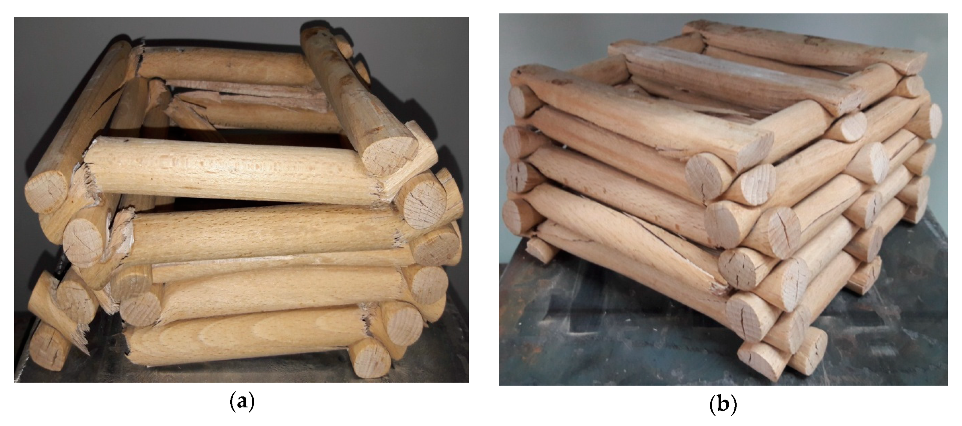
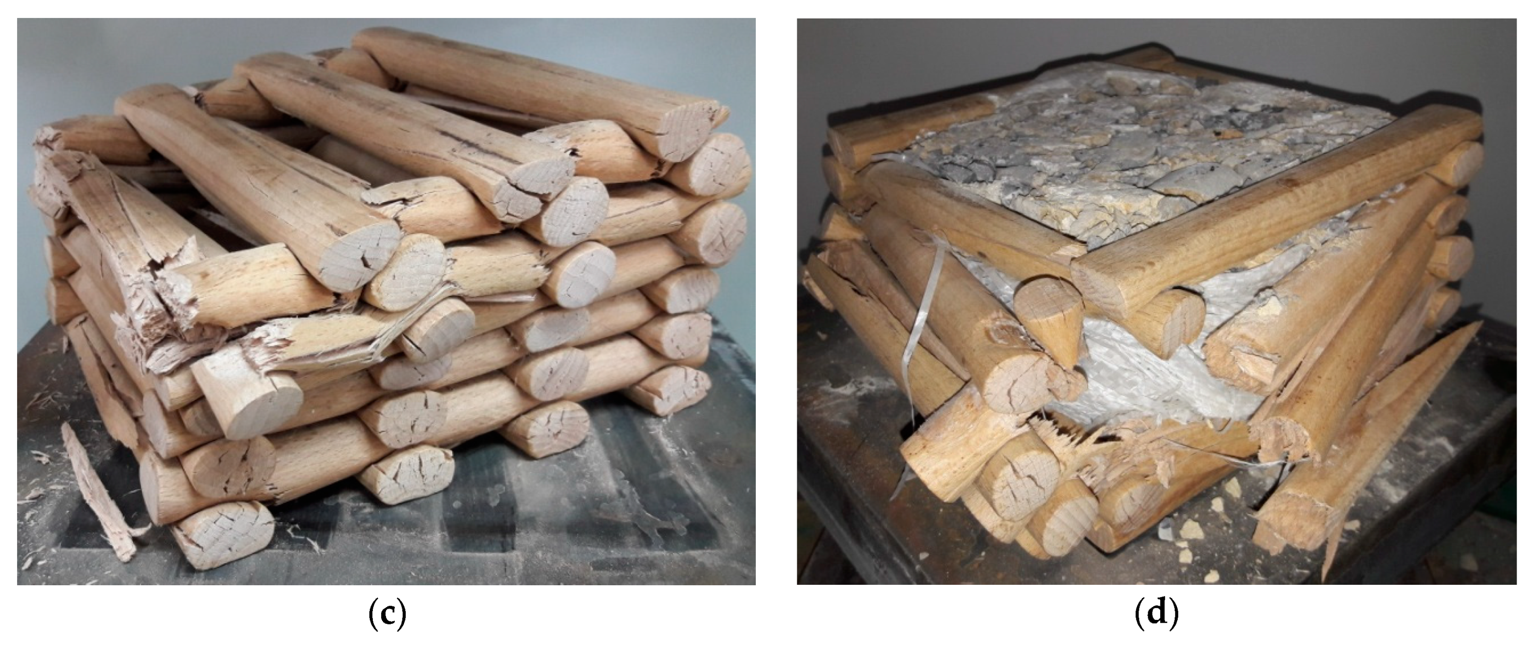
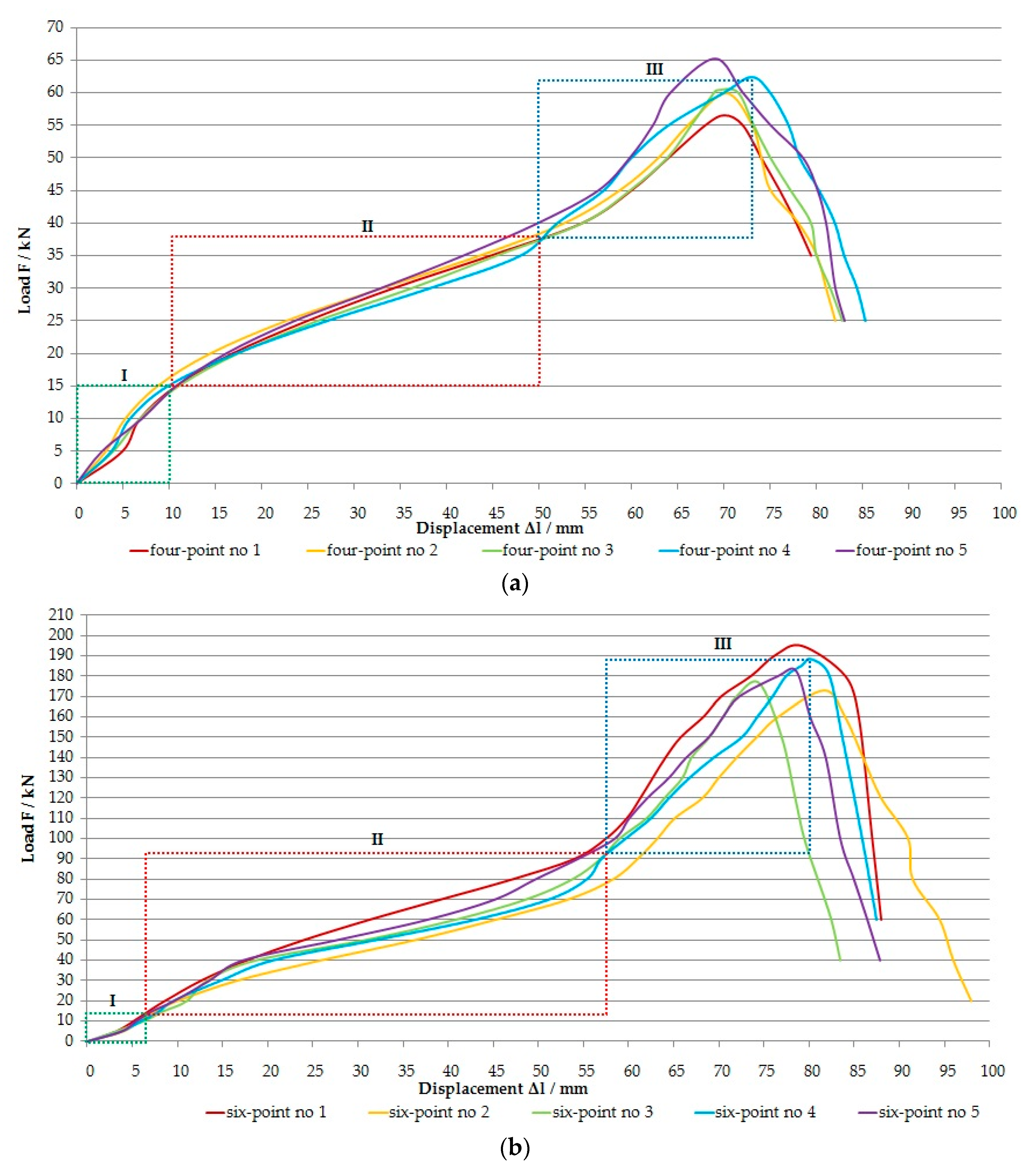
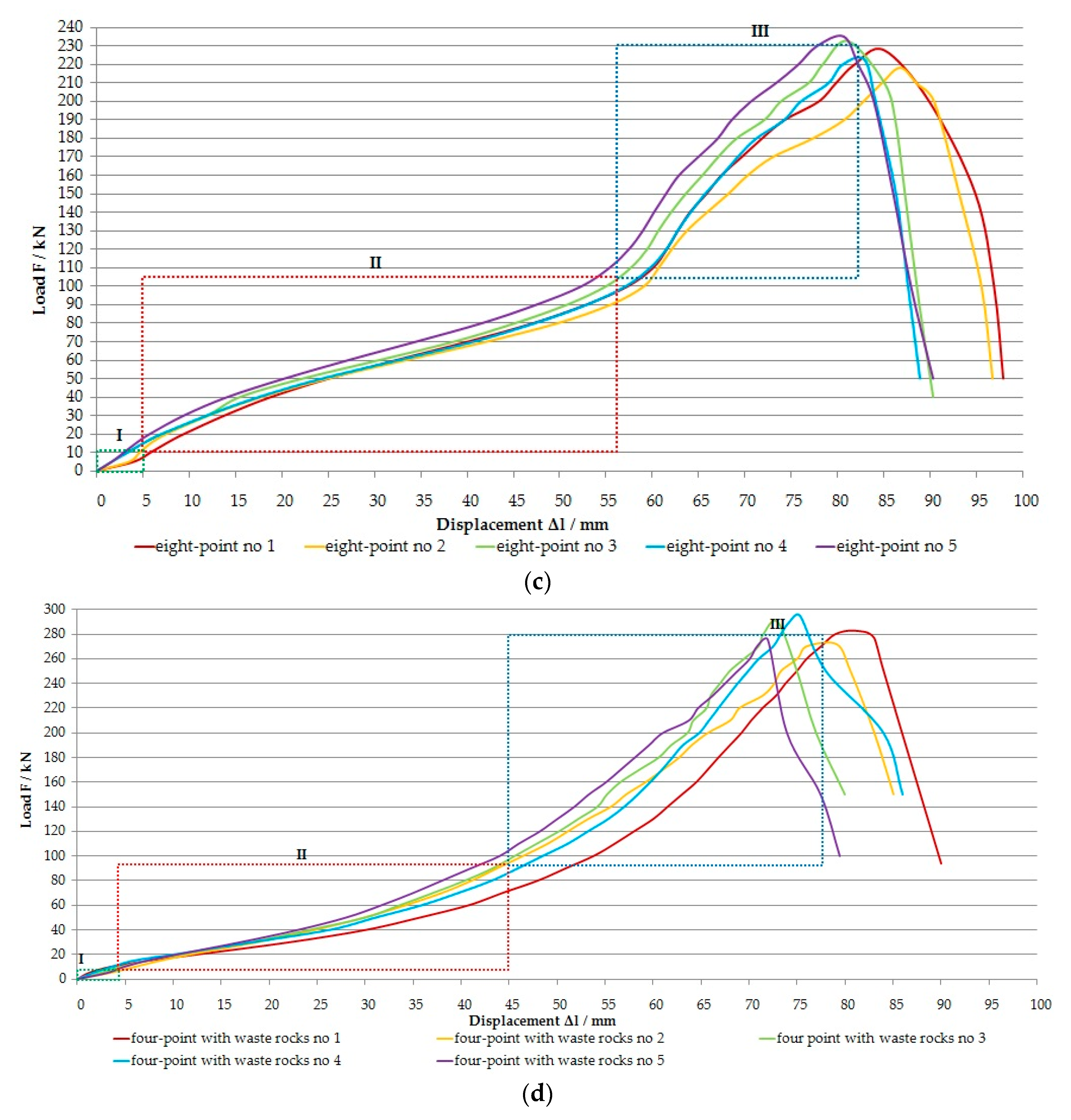
Laboratory compression tests on the wooden cribs were performed at the Department of Mining Engineering and Work Safety at the Faculty of Mining and Geoengineering, AGH University of Science and Technology in Krakow (Poland). The load was measured using three strain gauges, while a line encoder was used to measure displacement (Figure 7). The load rate was 0.5 kN/s. The sensors were connected to a universal measuring amplifier, QUANTUM MX840A, which was connected to a computer. The test results were monitored on an ongoing basis using Catman-Easy software. Each crib model was tested five times. The results of the compression tests on the models of cribs are presented in Table 1 and in Figure 8a–d. Detailed load-displacement characteristics of crib models are presented in Figure 9a–d.
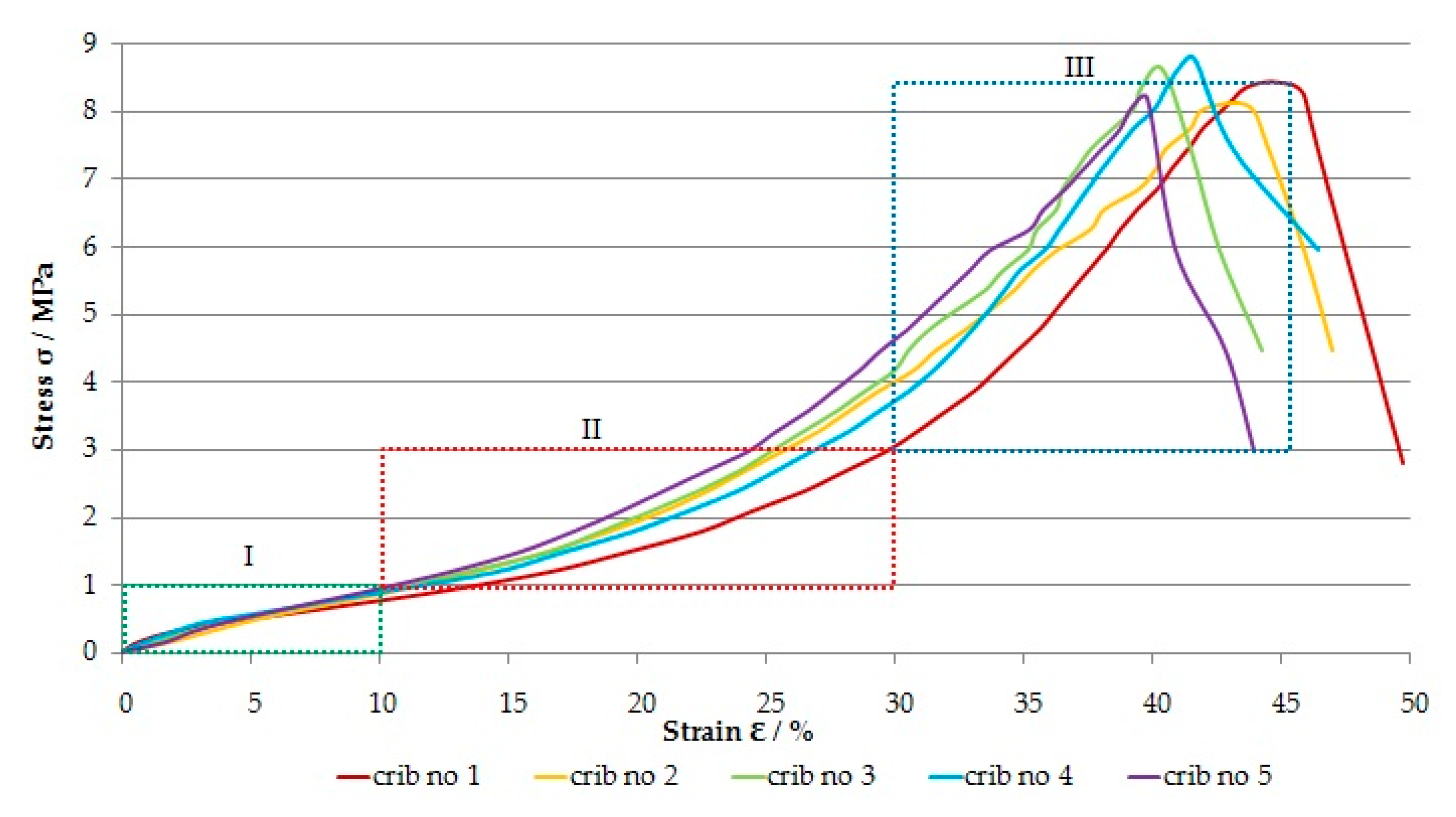
Average compressive strength of the wooden crib filled by waste rocks: Cs = 8.44 MPa.
Among the four-point, six-point and eight-point empty wooden cribs, the eight-point cribs had the best load-bearing capacity. The average value of the maximal load for eight-point wooden cribs was equal to 227 kN and was greater by 44 and 166.1 kN compared to the four-point and six-point cribs, respectively. On the other hand, filling the wooden cribs with waste rocks (dolomitic limestone) increased their load-bearing capacity by 56, 100, and 222.1 kN compared to the eight-point, six-point and four-point cribs, respectively. The average value of vertical deformation for the eight-point wooden empty cribs was equal to 83.3 mm and was greater by 10.3, 4.5, and 7.2 mm compared to the empty four-point and six-point cribs and the four-point cribs filled with waste rocks, respectively. Based on Table 1 it can be stated that the four-point wooden crib filled with waste rocks is characterized by the highest load-bearing capacity. One of the basic research goals was to use waste rocks in the wooden cribs. Therefore, in order to better understand the mechanism of cooperation between waste rocks and wooden cribs, the stress-strain characteristics are presented in Figure 10.
The surface area of the crib was determined as the sum of the surface of the wooden beams and the surface occupied by the waste rocks inside the crib, in accordance with Figure 6k. However, the load value was determined in accordance with Figure 9d. The average compressive strength (Cs) of the wooden crib filled with waste rocks was equal to 8.44 MPa. In Figure 10, three characteristic phases of cooperation between wooden cribs and waste rocks can be distinguished. The first phase is related to the initial adjustment of the space between the waste rocks and the beams of the crib. An initial elastic compression of the crib occurred, as well as the matching of the wooden beams’ connection. The stress and strain of the crib for this phase were equal to 1 MPa and 10%, respectively. In the second phase, the waste rocks took on the load, and the reduction in distance between the beams of the crib was limited by waste rocks. The stress and strain of the crib for this phase were equal to 3 MPa and 30%, respectively. The third phase continued until the maximal load capacity of the cribs was obtained. In this phase, the beams of the crib were damaged, the continuity of the mesh was broken, and the waste rocks spilled out. The stress and strain of the crib for this phase were equal to 8.8 MPa and 46%, respectively.

4. Numerical Modeling of Principal Stresses in the Inter-Room Pillars

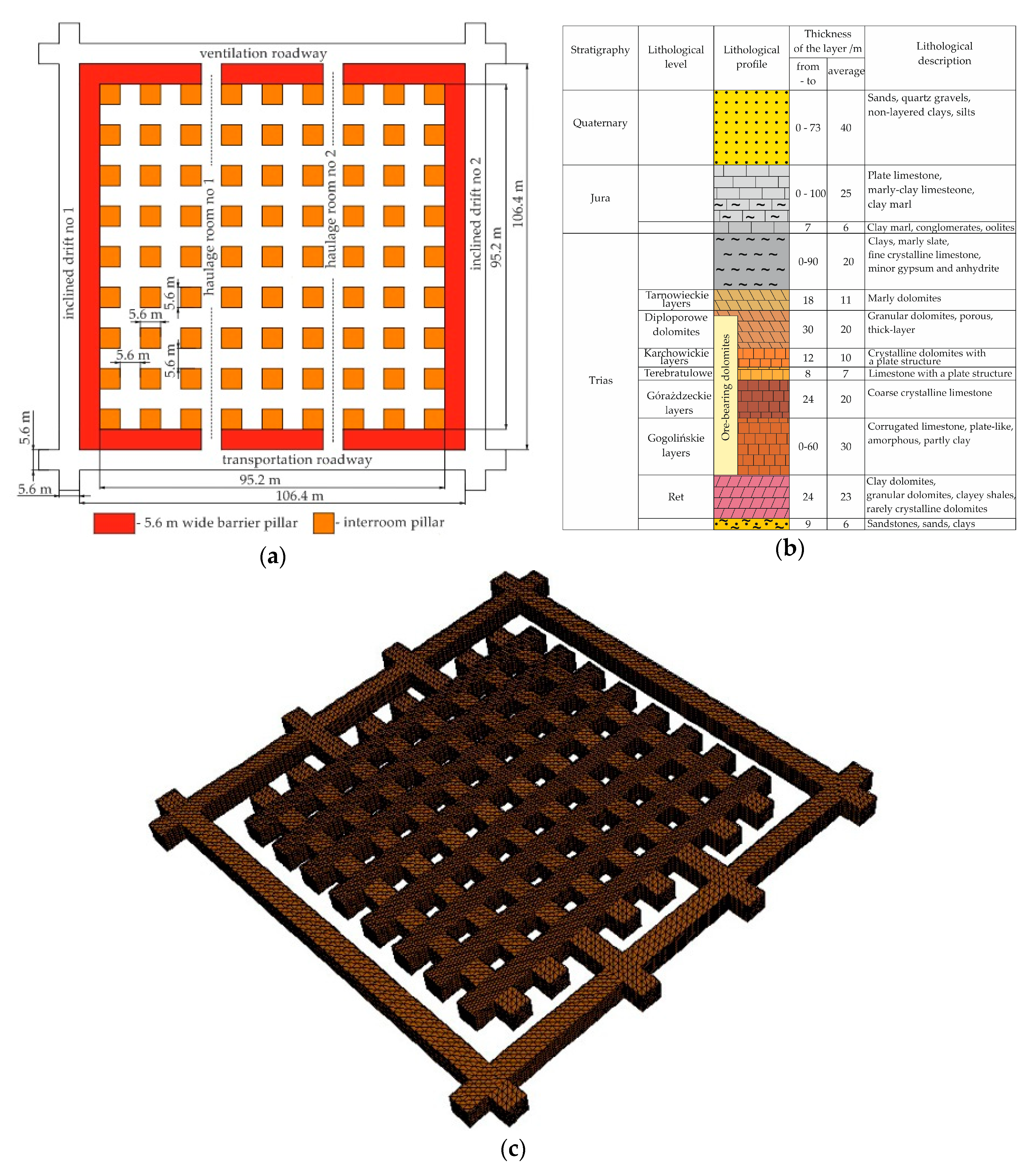
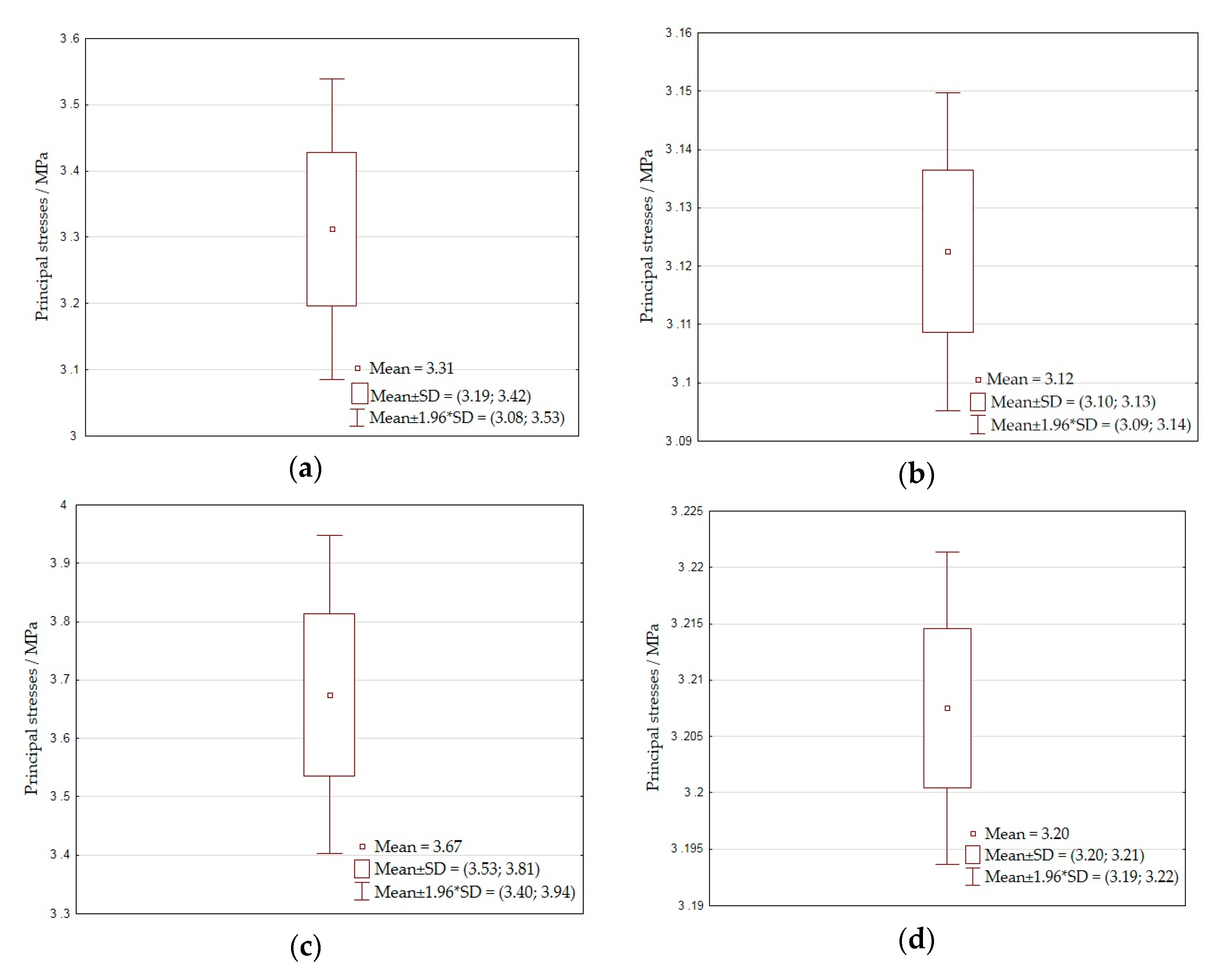
The room and pillar method was modeled in the Phase2 numerical software. In the numerical modeling, graded mesh and three-noded triangle elements were used. The total number of elements and nodes was 1034 and 581, respectively. Plain strain analysis was adjusted with the Gaussian elimination solver type. In the analysis, the maximal number of iterations and the tolerance were 500 and 0.001, respectively. Poor quality elements were defined as a side length ratio with a maximum to minimum ratio of more than 30; a minimal and maximal interior angle of less than 2 degrees and more than 175 degrees, respectively. The rock mass model was a flat 125 m × 125 m shield, which was fixed on three boundaries. Only from the surface side was the shield not restrained. The rooms and pillars were subjected to static loads resulting from the weight of overburden rocks. The main purpose of modeling was to determine the stresses in the inter-room pillars. Modeling was performed on four cases of the exploitation system: R1—rock pillars and empty rooms; R2—rock pillars and rooms filled with sand filling; R3—rock pillars replaced by wooden cribs filled with waste rocks; R4—rock pillars replaced by wooden cribs filled with waste rocks and rooms filled by sand filling. The model assumed that the length of the mining field side was 95.2 m (Figure 11a). The room excavations and pillars had a width and height of 5.6 m (Figure 11c) and were located at a depth of 110 m below the surface (Figure 11b). The strength, deformation and structural parameters of the rocks making up the rock pillars were determined experimentally on cylindrical samples 50 mm in diameter and 100 mm high, cut from rock lumps taken from the mining room in the Olkusz-Pomorzany mine. The waste rocks (dolomitic limesteone) used in this study were characterized by the following parameters: compressive strength 30.5 MPa; tensile strength 2.3 MPa; friction angle 42.3°; cohesion 0.46 MPa; Young’s modulus 25,000 MPa; Poisson’s ratio 0.24; unit weight 0.027 MN/m3. The results of the calculations are presented in Figure 12a–d and in Table 2. Additionally, in Figure 13a–d, the mean and standard deviation for the principal stresses are presented.
In the calculations, the Mohr—Coulomb shear strength criterion [24] was used, which is a linear failure criterion requiring two parameters, cohesion and friction angle, which were selected using the Rocklab program [24]. The Mohr—Coulomb criterion describes the linear relationship between normal and shear stresses (or maximal and minimal principal stresses) in the damaged zone. The quantities needed to determine the dependency sought are:
σ = σ 1 + σ 3 2 σ 1 σ 3 2 sin φ
τ = σ 1 σ 3 2 cos φ  
Using the expression for stress σ and τ in the limit state equation on a slip surface:
| τ | = σ tg φ + c
we get the following relationship:
σ 1 σ 3 2 cos φ = σ 1 + σ 3 2 tg φ σ 1 σ 3 2 sin φ 2 cos φ + c
where:
  • σ—total normal stress on the slip surface;
  • τ—shear stress on the slip surface;
  • σ1—major principal stress;
  • σ3—minor principal stress;
  • 1 + σ2)/2—horizontal coordinate of the Mohr circle center;
  • 1−σ3)/2—Mohr circle radius;
  • φ—effective angle of internal friction;
  • c—effective cohesion.
The principal stress value was determined using the Von Mises stress criterion. Von Mises stress is given by [24]:
σ VM = 3 · J
where J is given by:
J = 1 6 · ( σ 1 σ 2 ) 2 + ( σ 2 σ 3 ) 2 ( σ 3 σ 1 ) 2
where:
  • σ1—major principal stress;
  • σ2—intermediate principal stress;
  • σ3—minor principal stress.
In the research, the scale effect was taken into account according to Weibull’s theory [25], which shows that the strength of an element depends on its volume, which is expressed by the relationship:
R 1 R 0 = ( V 0 V 1 ) 1 m
where:
  • R0—compressive strength of the crib model filled with waste rocks;
  • R1—compressive strength of the crib filled with waste rocks on a geometric scale 1:1;
  • V0—volume of the crib model filled with waste rocks;
  • V1—volume of the crib filled with waste rocks on a geometric scale 1:1;
  • m—Weibull modulus; this can be estimated from the formula [26]:
m = 1.2 C V
where:
Cv—coefficient of variation of the strength of the material, defined as the ratio of the standard deviation to the average value. It was assumed in the study that the volume of the crib model filled with waste rocks was 0.00813 m3 (Figure 6k,l); the compressive strength determined experimentally under laboratory conditions was 8.44 MPa (Table 1); the volume of crib filled with waste rocks on a geometric scale of 1:1 was 175.61 m3; the material strength coefficient of variation (for models of cribs filled with waste rocks) Cv = 0.02484; the Weibull modulus m = 48.309. Taking into account the above data, the predicted compressive strength of the wooden cribs filled with waste rocks on a geometric scale 1:1 was 6.86 MPa.
For the room and pillar method with rock pillars, the mean value of the principal stresses was equal to 3.31 MPa. The replacement of rock pillars by the construction of wooden cribs filled with waste rocks (dolomitic limestone) caused the mean value of principal stresses to increase by 0.36 MPa. The filling of rooms with the sand backfilling process reduced the value of principal stresses by 0.19 and 0.47 MPa for rock pillars and pillars replaced with wooden cribs filled with waste rocks, respectively.

5. Results

The varied courses of the load-displacement characteristics are a reflection of the non-uniform manner of destruction of individual crib models. Based on Figure 9a–d, the range of variability of the stiffness of wooden cribs was calculated as a function of their compressibility (Figure 14 and Table 3).
Three characteristic stiffness phases can be distinguished for the empty crib models. The first phase is related to the initial elastic compression of the crib as well as the matching of the wooden beams’ connection. The range of variability of stiffness for this phase for four-point, six-point, and eight-point cribs is 1.5, 1.85, and 1.98 kN/mm, respectively. The second phase is associated with kneading the beams and reducing the distance between the beams of the crib. The distance between one beam and the other before loading was 15 mm. The range of stiffness variability for the second phase for four-point, six-point, and eight-point cribs is 0.55, 1.58, and 2.05 kN/mm, respectively. The third phase is associated with the increase in load until the maximal load is reached. In this phase, the crib loses its functionality; the beams of the crib become delaminated. The range of stiffness variability for the third phase for four-point, six-point, and eight-point cribs is 1.13, 4.21, and 4.63 kN/mm, respectively. The crib models, which were filled with waste rocks, were equipped with a polypropylene plastic mesh. The basic task of the mesh was to prevent the crushed rock from spilling out. It can be assumed that the mesh used contributed to a close fit of waste rocks inside the cribs. Three characteristic phases can also be distinguished for four-point cribs filled with waste rocks. The first phase is related to the initial adjustment of the space between the waste rocks and the beams of the crib. The stiffness of the crib for this phase is 1.77 kN/mm. In the second phase, the waste rocks take on the load, compared to empty cribs, and the reduction in distance between the beams of the crib is limited by waste rocks. The stiffness of the crib for this phase is 2.13 kN/mm. The third phase, as with the empty cribs, continues until the maximal load capacity of the cribs is obtained. In this phase, the beams of the crib are damaged, the continuity of the mesh is broken, and the waste rocks spill out. The stiffness of the crib for this phase is 5.87 kN/mm. The function of inter-room pillars is to maintain the stability of excavations. The stability of a pillar can be evaluated by calculating a factor of safety (FoS), which is the ratio of the pillar strength to the average stress in the pillar [27,28,29,30,31].
FoS = P strength P stress
where:
  • FoS—factor of safety;
  • Ps—pillar strength/MPa;
  • S—applied pillar stress/MPa.
A value of safety factor below 1 may contribute to the loss of functionality of the excavation stability [32,33]. The compressive strength of dolomite samples with a diameter of 50 mm and a height of 100 mm tested in laboratory conditions was 30 MPa. Hedley and Grant [34] proposed to determine the strength of the pillar taking into account the conversion factor of 0.7 for a sample diameter of 50 mm:
P strength = K · w 0.5 h 0.75
where:
  • K—strength of 0.3 m cubic sample = 0.7 × uniaxial compressive strength (UCS, 30MPa) (50 mm diameter sample)/MPa;
  • K = 0.7 × 30 = 21 MPa;
  • w—pillar width/m;
  • h—pillar height/m.
Taking into account the width and height of the pillar of 5.6 m, according to Equation (10), the strength of the pillar was 13.65 MPa. The value of the rock pillar’s strength therefore is 6.79 MPa higher than for wooden cribs filled with waste rocks. To estimate the value of the factor of safety for cribs filled with waste rocks, the pillar strength was calculated to be 6.86 MPa, while the applied pillar stress value calculated on the basis of numerical methods in accordance with Table 2 was in the range of 3.13 to 3.90 MPa. Substituting the calculated values of the pillar strength and applied pillar stress into Equation (9) it can be concluded that the factor of safety for rock pillars replaced by cribs filled with waste rocks is 1.75. Filling the rooms with a hydraulic sand filling increases the factor of safety to the value of 2.19. In a field of exploitation with a surface area 9063.04 m2 (Figure 11a), inter-room pillars occupy 28.02% of the area. The metals that are contained in the inter-room pillars constitute mining losses. The possibility of exploiting the pillars and replacing them with the construction of wooden cribs filled with waste rocks can contribute to a reduction in mining losses, while increasing the level of extraction. Assuming that the volume of a cubic pillar with a side length of 5.6 m is 175.61 m3, that the volume density is 2700 kg/m3, and that the average content of zinc and lead in the pillar is 2%, this means that the resources in one pillar are approximately 9.48 Mg. Considering the average prices of zinc and lead on the London Metal Exchange [35], which as of 2 July 2020 are 2035.50 and 1768.50 USD/Mg respectively, and the calculated resources for one pillar, this means that the value of metals contained in one pillar is around USD 36,028. The total costs of mining the pillar and replacing it with wooden cribs filled with waste rocks, include the cost of excavating the pillar with explosives; the cost of energy related to the ventilation of the rooms; the cost of securing the excavation with a rock bolt support; the cost of transporting the ore; the costs of the processing plant; the cost of purchasing and transporting wooden beams; the cost of transporting waste rocks from excavations to use in the room and pillar method. The estimated total costs of mining the rock pillar and replacing it with a wooden crib filled with waste rocks constitute 80% to 85% of the value of the metals contained in the pillar. For mining excavations where there are no useful minerals, there is no need to take them to the surface; these rocks can be used to fill the wooden cribs. This solution significantly reduces operating costs, while contributing to the management of waste rocks in underground mining excavations, which is environmentally friendly.

6. Conclusions

Based on the results of the laboratory tests on mining crib models, it can be stated that:
  • the four-point empty crib, built of 22 beams, showed an average capacity of 60.9 kN and an average specific deformation of 35.5%;
  • increasing the number of connections in the crib increased its load;
  • the six-point empty crib was characterized by a load capacity of more than three times greater and an average specific deformation greater by 4.25% compared to the four-point crib;
  • the eight-point empty crib was characterized by a load capacity of more than three and a half times greater and an average specific deformation greater by 6.5% compared to the four-point crib;
  • filling the four-point crib with waste rocks (crushed dolomite with a diameter of 10–25 mm) meant that its capacity was more than four and a half times greater and that the average specific deformation increased by 2.9% compared to the four-point empty crib;
  • the rigidity of empty four-point, six-point, and eight-point cribs decreases with increasing compressibility (up to 30%); above 30% compressibility, the stiffness of the cribs increases;
  • the stiffness of four-point cribs filled with waste rocks increases with increasing compressibility.
Based on the numerical calculations for the room and pillar method in the mining field in cases with a side length equal to 95 m, in which the width, length, and height of the pillar and room are 5.6 m, for the conditions of the Olkusz-Pomorzany zinc and lead mine, it can be concluded that:
  • the maximal value of principal stresses in the inter-room rock pillars is 3.50 MPa;
  • the replacement of rock pillars by means of wooden cribs filled with waste rocks causes an increase in principal stresses in the inter-room pillars by 0.4 MPa in comparison with rock pillars;
  • the value of the factor of safety for the inter-room rock pillars ranges from 3.9 to 4.25 and ranges from 1.75 to 2.19 when rock pillars are replaced by wooden cribs filled with waste rocks.
The new construction of a wooden crib can significantly increase the level of extraction, while reducing mining losses. In addition, from an environmental point of view, filling wooden cribs with waste rocks contributes to development in situ without the need to store materials on the surface.

Funding

This paper was prepared as part of AGH’s scientific subsidy, under number 16.16.100.215.

Conflicts of Interest

The author wishes to confirm that there are no known conflicts of interest associated with this publication and that there has been no significant financial support for this work that could have influenced its outcome.

References

  1. Barczak, T.; Tastillo, C. Evaulation of Multitimber Wood Crib Support; Report of Investigations 9341; United States Department of the Interior. Bureau of Mines: Washington, DC, USA, 1991.
  2. Korzeniowski, W.; Skrzypkowski, K. Comparative investigations of the load capacity and load-strain characteristics of chocks with different filling. Min. Rev. 2012, 68, 36–40. [Google Scholar]
  3. Korzeniowski, W.; Skrzypkowski, K.; Szumiński, A. Characteristics of a model of mining wooden chock with increased load capacity. Min. Rev. 2014, 70, 26–33. [Google Scholar]
  4. Daehnke, A.; Taggart, P.N.; Roberts, M.K.C. Evaluation of the influence of grout prestressing systems on the performance of timber packs: Static and dynamic considerations. J. S. Afr. Inst. Min. Metall. 1995, 96, 41–46. [Google Scholar]
  5. Dison, L.; Smith, A.C.S. Cempaks: Stope and gully supports. In Proceedings of the 6th International Symposium on Ground Support in Mining and Civil Engineering Construction, Cape Town, South Africa, 31 March–3 April 2008; Stacey, T.R., Malan, D.F., Eds.; Southern African Institute of Mining and Metallurgy: Cape Town, South Africa, 2008; pp. 289–298. [Google Scholar]
  6. Mining Product Developments. Available online: http://www.miningproducts.co.za/mining-products.html (accessed on 19 March 2020).
  7. Skrzypkowski, K. Strengthening the room excavation through the use of additional support in the form of wooden props in underground ore copper mines. Bull. Inst. Non-Ferr. Met. 2017, 62, 10–15. [Google Scholar] [CrossRef]
  8. Strata Worldwide. Available online: https://www.strataworldwide.com (accessed on 12 March 2020).
  9. Kushwaha, A.; Singh, S.K.; Tewari, S.; Sinha, A. Empirical approach for designing of support system in mechanized coal pillar mining. Int. J. Rock Mech. Min. 2010, 47, 1063–1078. [Google Scholar] [CrossRef]
  10. Li, Y.; Li, K.; Feng, X.; Cai, M. Development and evaluation of artificial expandable pillars for hard rock mining. Int. J. Rock Mech. Min. 2018, 110, 68–75. [Google Scholar] [CrossRef]
  11. Luan, H.; Jiang, Y.; Lin, H.; Li, G. Development of a New Gob-Side Entry-Retaining Approach and Its Application. Sustainability 2018, 10, 470. [Google Scholar] [CrossRef] [Green Version]
  12. Hadjigeorgiu, J.; Habiyaremye, F.; Lessard, J.S.; Andrieux, P. An investigation into the behavior of shotcrete pillars. In Rock Support and Reinforcement Practice in Mining; Villaescusa, E., Windsor, C.R., Thompson, A., Eds.; Balkema: Rotterdam, The Netherlands, 1999; pp. 183–192. [Google Scholar]
  13. Kang, H.; Lv, H.; Zhang, X.; Gao, F.; Wu, Z.; Wang, Z. Evaluation of the Ground Response of a Pre-driven Longwall Recovery Room Supported by Concrete Cribs. Rock Mech. Rock Eng. 2016, 49, 1025–1040. [Google Scholar] [CrossRef]
  14. Cao, S.; Zheng, D.; Yilmaz, E.; Yin, Z.; Xue, G.; Yang, F. Strength development and microstructure characteristics of artificial concrete pillar considering fiber type and content effects. Constr. Build. Mater. 2020, 256, 119408. [Google Scholar] [CrossRef]
  15. Skrzypkowski, K. The influence of dimension of mining crib model filled by waste rock on the course of load—Displacement characteristic. Bull. Miner. Energy Econ. Res. Inst. Pol. Acad. Sci. 2017, 99, 131–141. [Google Scholar]
  16. Korzeniowski, W.; Skrzypkowski, K.; Szumiński, A.; Zagórski, K. Laboratory investigations of the load capacity and load-strain characteristics of four-point cribs filled with waste rocks. Bull. Inst. Non-Ferr. Met. 2015, 60, 303–308. [Google Scholar] [CrossRef]
  17. Skrzypkowski, K.; Korzeniowski, W.; Zagórski, K.; Zagórska, A. Flexibility and load-bearing capacity of roof bolting as functions of mounting depth and hole diameter. Energies 2019, 12, 3754. [Google Scholar] [CrossRef] [Green Version]
  18. Skrzypkowski, K.; Korzeniowski, W.; Zagórski, K.; Zagórska, A. Adjustment of the Yielding System of Mechanical Rock Bolts for Room and Pillar Mining Method in Stratified Rock Mass. Energies 2020, 13, 2082. [Google Scholar] [CrossRef] [Green Version]
  19. Malan, D.F.; Napier, J.A.L. Rockburst support in shallow-dipping tabular stopes at great depth. Int. J. Rock Mech. Min. 2018, 112, 302–312. [Google Scholar] [CrossRef] [Green Version]
  20. Polish Geological Institute. Available online: https://www.pgi.gov.pl/en (accessed on 26 April 2020).
  21. State Mining Authority. Ordinance Minister of Environment of July 1, 2015 on the Geological Documentation of a Mineral Deposit, Excluding Hydrocarbons. Available online: http://www.wug.gov.pl/english/polish_law (accessed on 1 May 2020).
  22. Skrzypkowski, K. Crib in Mining Industry. Poland Patent PL233119B1, 30 September 2019. [Google Scholar]
  23. Skrzypkowski, K. The influence of room and pillar method geometry on the deposit utilization rate and rock bolt load. Energies 2019, 12, 4770. [Google Scholar] [CrossRef] [Green Version]
  24. Rocscience. Available online: https://www.rocscience.com (accessed on 11 May 2020).
  25. Weibull, W. A statistical distribution function of wide applicability. J. App. Mech. 1951, 18, 293–297. [Google Scholar]
  26. Zweben, C. Designer’s corner. Is there a size effect in composites? Composites 1994, 25, 451–454. [Google Scholar] [CrossRef]
  27. Esterhuizen, G.S.; Dolinar, D.R.; Ellenberger, J.L. Pillar strength in underground stone mines in the United States. Int. J. Rock Mech. Min. 2011, 48, 42–50. [Google Scholar] [CrossRef]
  28. Deghan, S.; Shahriar, K.; Maarefvand, P.; Goshtasbi, K. 3-D numerical modelling of Domino failure of hard rock pillars in Fetr6 Chromite Mine, Iran, and comparison with empirical methods. J. Cent. South Univ. 2013, 20, 541–549. [Google Scholar] [CrossRef]
  29. Verma, A.K. A comparative study of various empirical methods to estimate the factor of safety of coal pillars. Am. J. Mining Metall. 2014, 2, 17–22. [Google Scholar] [CrossRef]
  30. Yu, Y.; Chen, S.-E.; Deng, K.-Z.; Fan, H.-D. Long-Term Stability Evaluation and Pillar Design Criterion for Room-and-Pillar Mines. Energies 2017, 10, 1644. [Google Scholar] [CrossRef] [Green Version]
  31. Jessu, K.V.; Spearing, A.J.S.; Sharifzadeh, M. A Parametric Study of Blast Damage on Hard Rock Pillar Strength. Energies 2018, 11, 1901. [Google Scholar] [CrossRef] [Green Version]
  32. Martin, C.D.; Maybee, W.G. The strength of hard-rock pillars. Int. J. Rock Mech. Min. 2000, 37, 1239–1246. [Google Scholar] [CrossRef]
  33. Van der Merwe, J.N. Coal pillar strength analysis based on size at the time of failure. J. S. Afr. Inst. Min. Metall. 2019, 119, 681–691. [Google Scholar] [CrossRef]
  34. Hadley, D.G.G.; Grant, F. Stope and pillar design for the Elliot Lake uranium mines. Can. Inst. Min. Metall. Bull. 1972, 65, 37–44. [Google Scholar]
  35. London Metal Exchange. Available online: https://www.lme.com/en-GB/Metals/Non-ferrous/ (accessed on 2 July 2020).
Figure 1. Application of wooden cribs to maintain the roadway for the next longwall: (a) Arrangement of wooden cribs in a maingate; (b) General view of the wooden crib.
Energies 13 03564 g001
Figure 2. Cribs in Polish ore mining: (a) Support of the widened room in the room and pillar method with roof sag in the Legnicko-Głogów Copper District in Poland (the use of cribs in the phase of cutting technological pillars); (b) Residual pillar; (c) General view of crib; (d) Support of the widened room in zinc and lead ore mining in Poland; (e) Joining beams with steel clamps.
Energies 13 03564 g002
Figure 3. Division of geological resources.
Energies 13 03564 g003
Figure 4. Room and pillar method with hydraulic backfilling: (a) Division of the exploitation field; (b) Technological pillar with sphalerite and galena minerals in the Olkusz-Pomorzany mine in Poland; (c) Construction of a wooden filling dam with a filling pipeline.
Energies 13 03564 g004
Figure 5. General view of mining cribs models: (a) Empty eight-point, six-point, four-point, and four-point filled by waste rocks; (b) Waste rocks; (c) Connection of wooden beams by means of concave round notches.
Energies 13 03564 g005
Figure 6. Multi-point cribs: (a) Four-point, general view; (b) Four-point, top view; (c) Four-point, side view; (d) Six-point, general view; (e) Six-point, top view; (f) Six-point, side view; (g) Eight-point, general view; (h) Eight-point, top view; (i) Eight-point, side view; (j) Four-point filled with waste rocks, general view; (k) Four-point filled with waste rocks, top view; (l) Four-point filled with waste rocks, side view.
Energies 13 03564 g006aEnergies 13 03564 g006b
Figure 7. A scheme of the laboratory stand: 1—computer, 2—measuring amplifier, 3—force sensors, 4—displacement sensor, 5—model of crib, 6—lower base, 7—upper base, 8—hydraulic cylinder, 9—machine base, 10—driven cross head, 11—screw, 12—hydraulic pump, 13—control panel.
Energies 13 03564 g007
Figure 8. Models of the wooden cribs after compression tests: (a) Four-point; (b) Six-point; (c) Eight-point; (d) Four-point filled with waste rocks.
Energies 13 03564 g008aEnergies 13 03564 g008b
Figure 9. Load-displacement of the wooden crib models: (a) Four-point; (b) Six-point; (c) Eight-point; (d) Four-point filled with waste rocks.
Energies 13 03564 g009aEnergies 13 03564 g009b
Figure 10. Stress-strain characteristics of the wooden crib models filled with waste rocks.
Energies 13 03564 g010
Figure 11. Mining and geological conditions in the Olkusz-Pomorzany area in Poland: (a) Design of the room and pillar method; (b) Lithological profile for the designed region; (c) Perspective view of the room and pillar method.
Energies 13 03564 g011
Figure 12. Principal stress for the designed room and pillar method for four cases of exploitation: (a) Rock pillars and empty rooms (R1); (b) Rock pillars and rooms filled with hydraulic sand filling (R2); (c) Rock pillars replaced by wooden cribs filled with waste rocks and empty rooms (R3); (d) Rock pillars replaced by wooden cribs filled with waste rocks and rooms filled with hydraulic sand filling (R4).
Energies 13 03564 g012
Figure 13. Mean and standard deviation (SD) for principal stresses in relation to the designed room and pillar method: (a) Rock pillars and empty rooms (R1); (b) Rock pillars and rooms filled with hydraulic sand filling (R2); (c) Rock pillars replaced by wooden cribs filled with waste rocks and empty rooms (R3); (d) Rock pillars replaced by wooden cribs filled with waste rocks and rooms filled with hydraulic sand filling (R4).
Energies 13 03564 g013
Figure 14. The stiffness of the wooden cribs for increasing compressibility.
Energies 13 03564 g014
Table 1. Load-displacement parameters of tested wooden cribs.
Crib ModelMaximal Load
F/kN
Vertical Displacement Δl/mm (at Maximal Load)Average Specific Deformation
ε/%
FromToAverageFromToAverage
Four-point56.565.260.963.97370.335.15
Six-point17219418374.581.778.839.40
Eight-point22223522780.786.883.341.65
Four-point filled with waste rocks2712952837279.176.138.05
Table 2. Summary of numerical modeling results for four cases.
CasePrincipal Stresses Occurring in the Inter-Room Pillar
/MPa
NoDescriptionsMinimalMaximal
R1Rock pillars and empty rooms3.253.50
R2Rock pillars and rooms filled with hydraulic sand filling3.103.13
R3Rock pillars replaced by wooden cribs filled with waste rocks and empty rooms3.603.90
R4Rock pillars replaced by wooden cribs filled with waste rocks and rooms filled with hydraulic sand filling3.193.21
Table 3. Comparison of the stiffness of the wooden cribs for increasing compressibility.
Compressibility C/%Four-Point CribSix-Point CribEight-Point CribFour-Point Crib with Waste Rocks
Stiffness S/kN/mm
101.2522.451.65
200.871.461.851.67
300.751.401.802.30
400.772.052.603.72