Comparison of FPGA and Microcontroller Implementations of an Innovative Method for Error Magnitude Evaluation in Reed–Solomon Codes


Abstract
1. Introduction
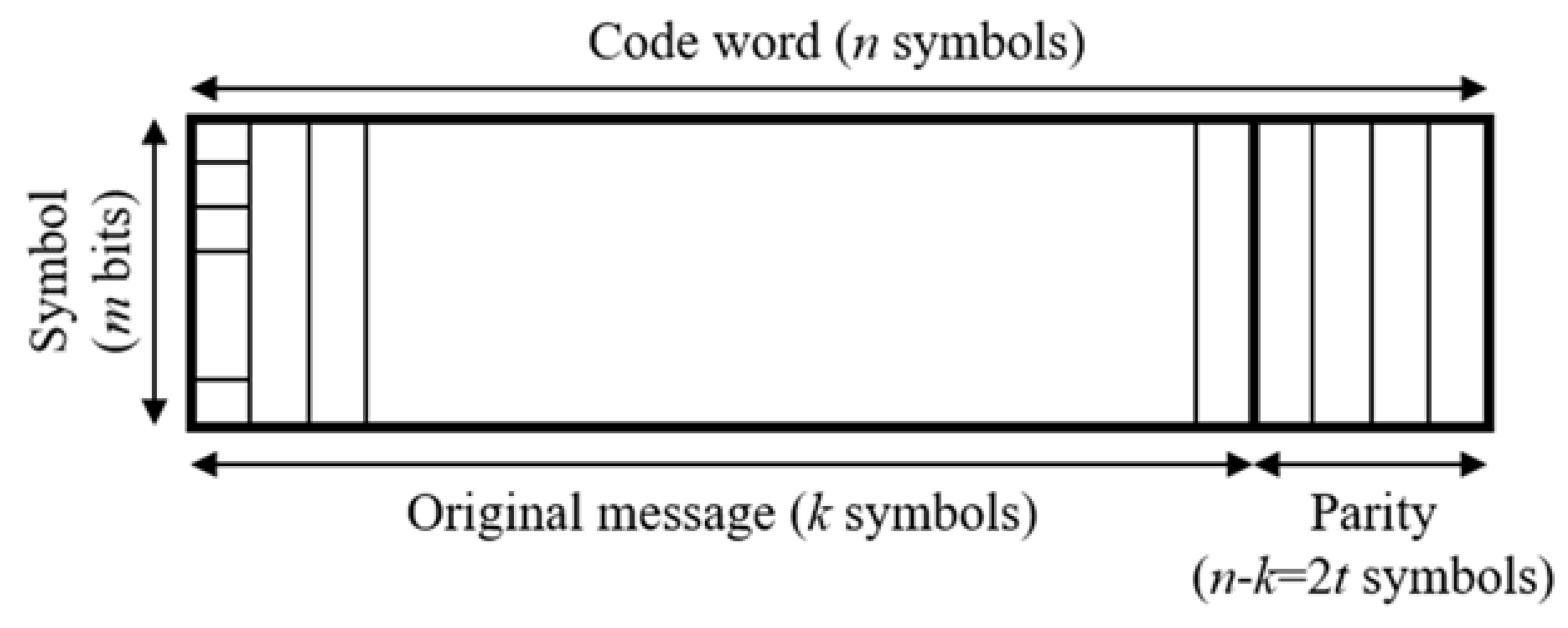
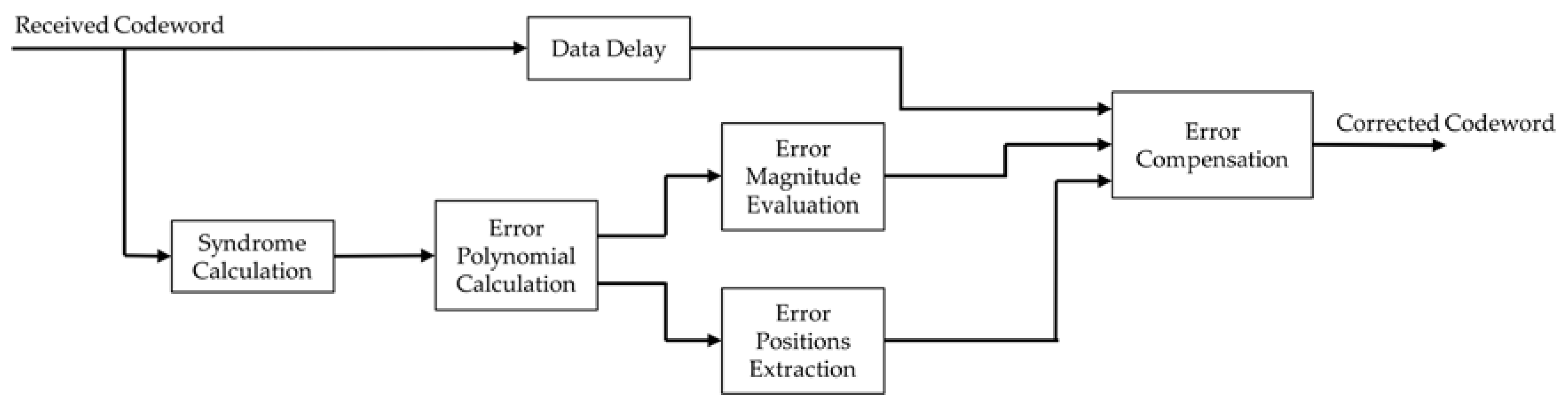
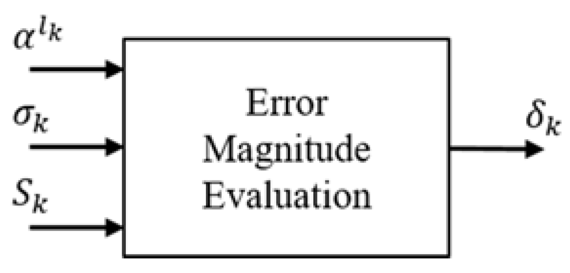
2. Error Magnitude Evaluation in Reed–Solomon Codes
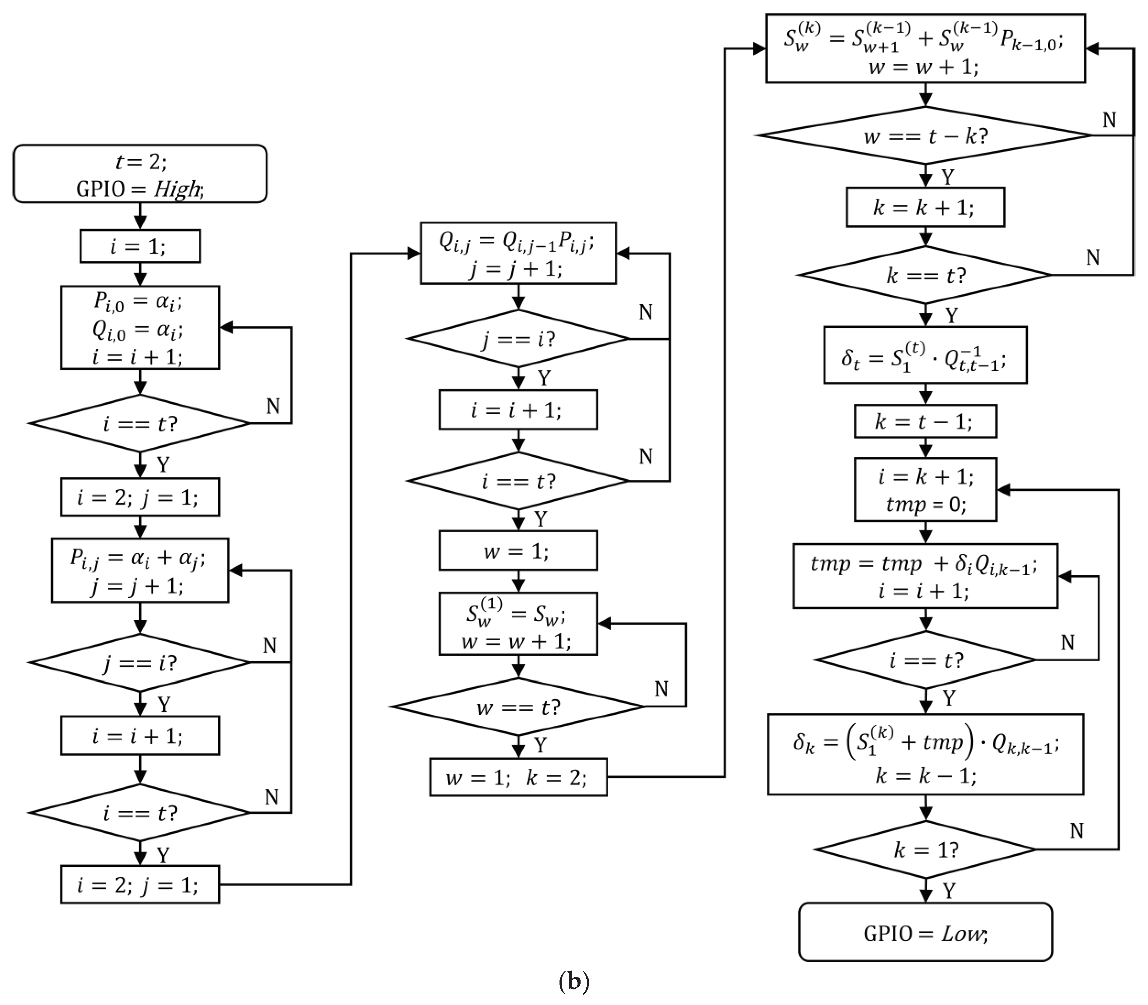
2.1. Forney Method
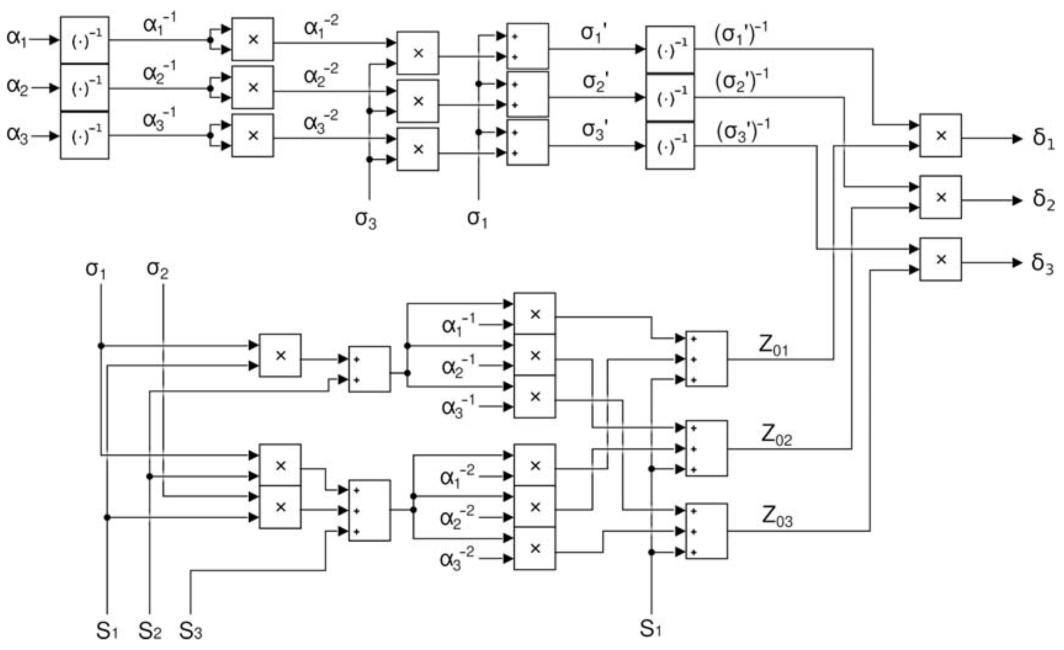
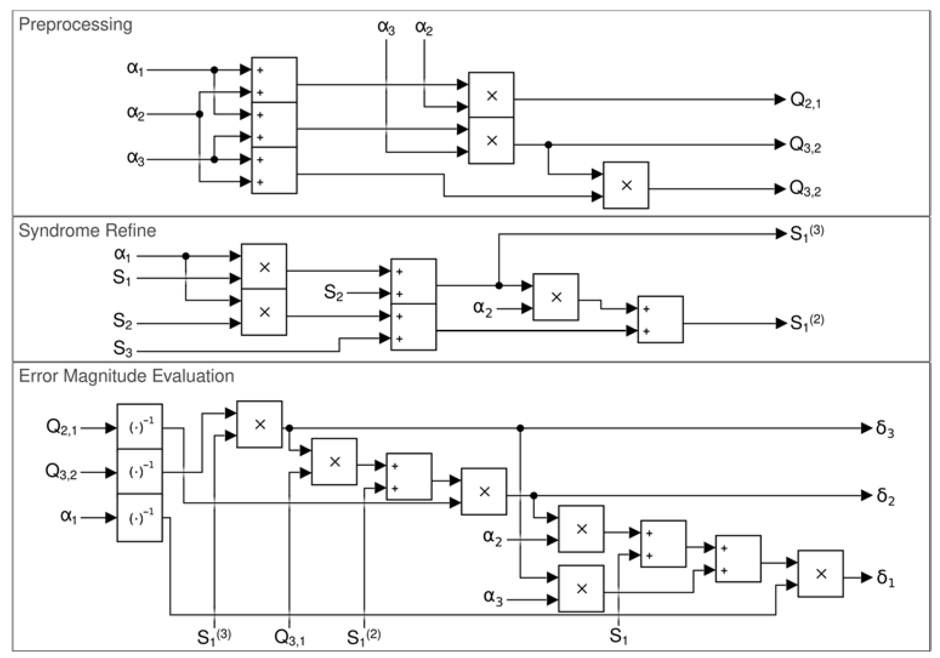
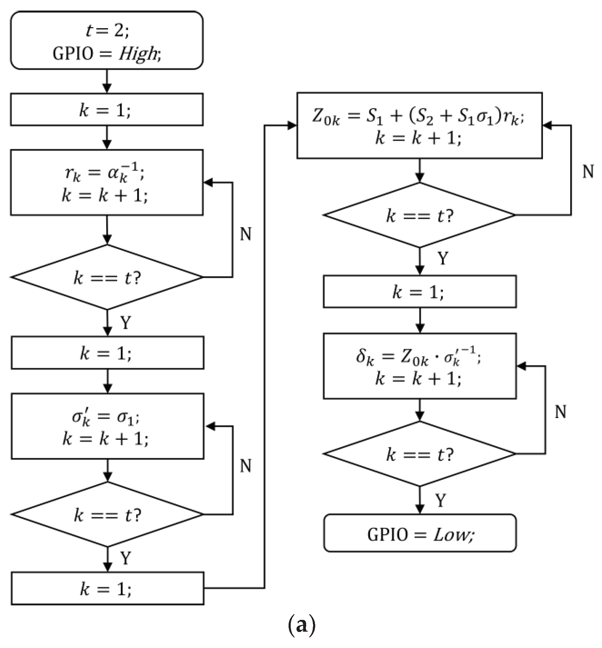
2.2. Lu Method
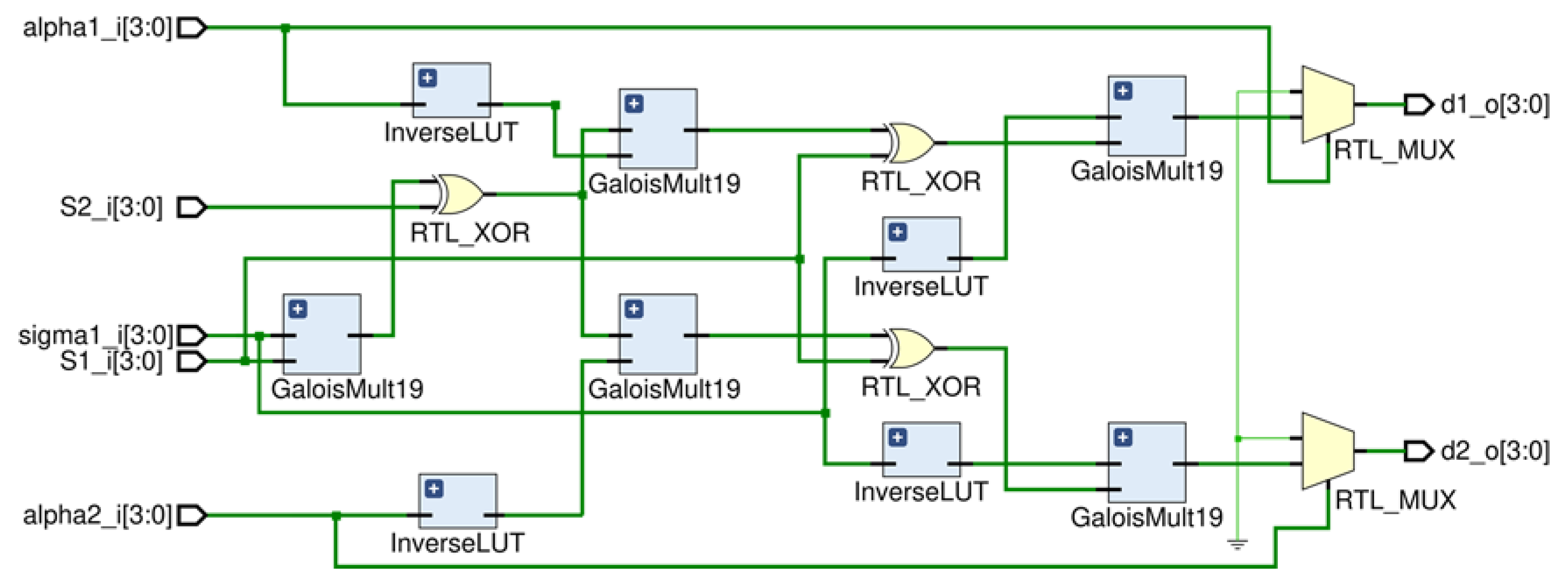
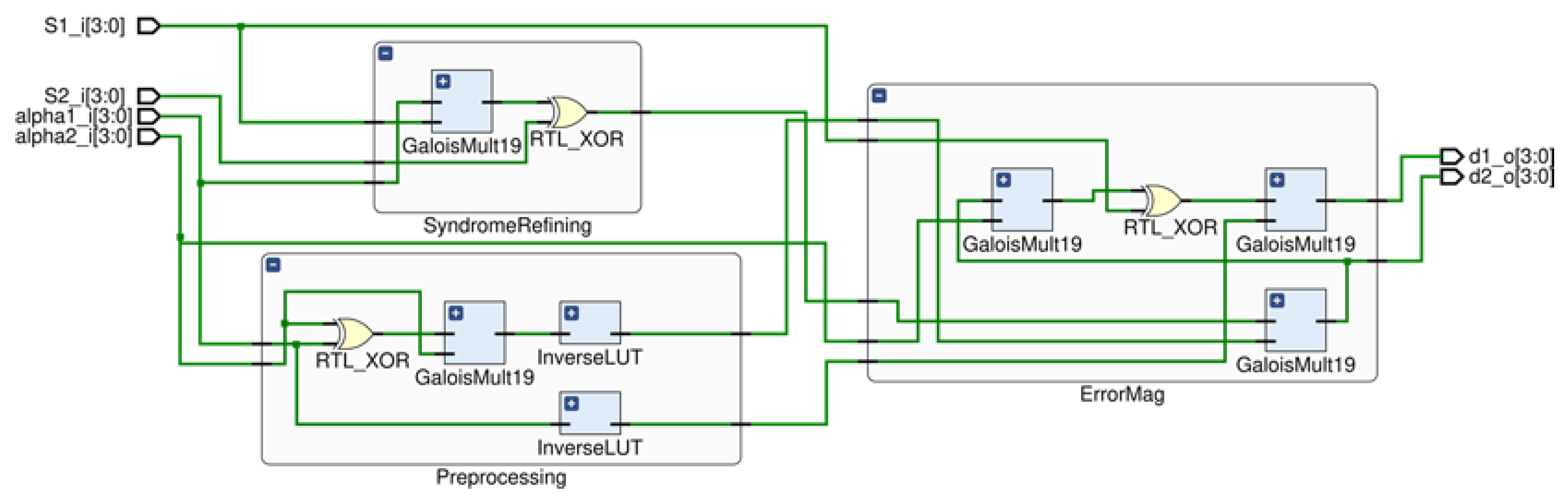
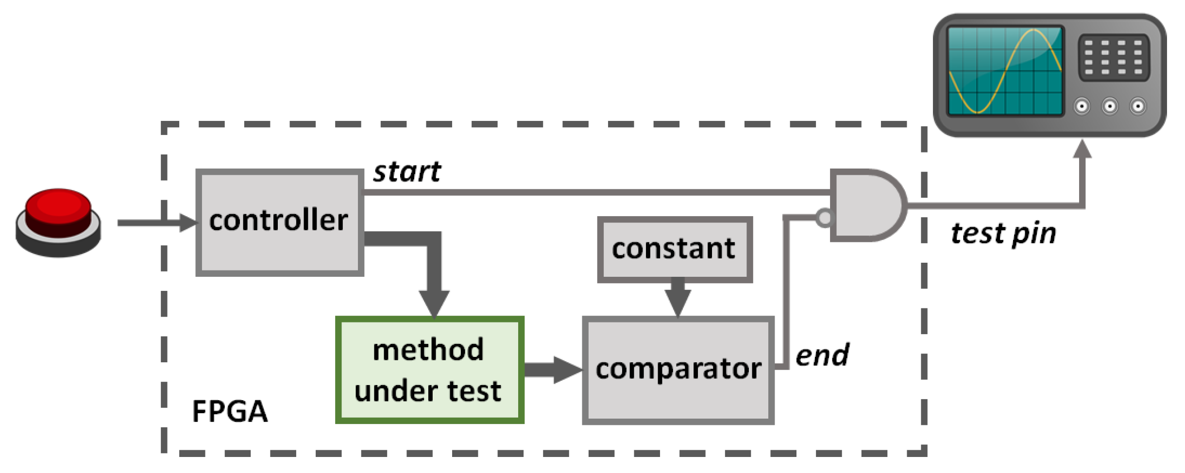
3. Hardware Configuration
4. Results and Discussion
5. Conclusions
Author Contributions
Funding
Conflicts of Interest
References
- Wang, J.; Yang, J.Y.; Fazal, I.M.; Ahmed, N.; Yan, Y.; Huang, H.; Ren, Y.; Yue, Y.; Dolinar, S.; Tur, M.; et al. Terabit free-space data transmission employing orbital angular momentum multiplexing. Nat. Photonics 2012, 6, 488–496. [Google Scholar] [CrossRef]
- Saltzberg, B.R. Performance of an Efficient Parallel Data Transmission System. IEEE Trans. Commun. Technol. 1967, 15, 805–811. [Google Scholar] [CrossRef]
- Peterson, W.W.; Brown, D.T. Cyclic Codes for Error Detection. Proc. IRE 1961, 49, 228–235. [Google Scholar] [CrossRef]
- Zhang, Z. Linear network error correction codes in packet networks. IEEE Trans. Inf. Theory 2008, 54, 209–218. [Google Scholar] [CrossRef]
- McAuley, A.J. Reliable Broadband Communication Using a Burst Erasure Correcting Code. In Proceedings of the ACM Symposium on Communications Architectures and Protocols, SIGCOMM, Philadelphia, PA, USA, 26–28 September 1990; Association for Computing Machinery Inc.: New York, NY, USA, 1990; pp. 297–306. [Google Scholar]
- Sudan, M. Decoding of Reed Solomon Codes beyond the Error-Correction Bound. J. Complexity 1997, 13, 180–193. [Google Scholar] [CrossRef]
- Sathananathan, K.; Tellambura, C. Forward Error Correction Codes to Reduce Intercarrier Interference in OFDM. In Proceedings of the ISCAS 2001–2001 IEEE International Symposium on Circuits and Systems, Sydney, Australia, 6–9 May 2001; IEEE: Piscataway, NJ, USA, 2002; Volume 4, pp. 566–569. [Google Scholar]
- Hamming, R.W. Error Detecting and Error Correcting Codes. Bell Syst. Tech. J. 1950, 29, 147–160. [Google Scholar] [CrossRef]
- Bose, R.C.; Ray-Chaudhuri, D.K. On a class of error correcting binary group codes. Infect. Control 1960, 3, 68–79. [Google Scholar] [CrossRef]
- Hocquenghem, A. Codes correcteurs d’erreurs. Chiffres 1959, 2, 147–156. [Google Scholar]
- Poolakkaparambil, M.; Mathew, J.; Jabir, A. Multiple Bit Error Tolerant Galois Field Architectures Over GF(2m). Electronics 2012, 1, 3–22. [Google Scholar] [CrossRef]
- Carlitz, L. The Arithmetic of Polynomials in a Galois Field. Am. J. Math. 1932, 54, 39. [Google Scholar] [CrossRef]
- Reed, I.S.; Solomon, G. Polynomial Codes Over Certain Finite Fields. J. Soc. Ind. Appl. Math. 1960, 8, 300–304. [Google Scholar] [CrossRef]
- Kieseberg, P.; Leithner, M.; Mulazzani, M.; Munroe, L.; Schrittwieser, S.; Sinha, M.; Weippl, E. QR Code Security. In Proceedings of the MoMM 2010—8th International Conference on Advances in Mobile Computing and Multimedia, Paris, France, 8–10 November 2010; pp. 430–435. [Google Scholar]
- Sun, X.; Skillman, D.R.; Hoffman, E.D.; Mao, D.; McGarry, J.F.; McIntire, L.; Zellar, R.S.; Davidson, F.M.; Fong, W.H.; Krainak, M.A.; et al. Free space laser communication experiments from Earth to the Lunar Reconnaissance Orbiter in lunar orbit. Opt. Express 2013, 21, 1865. [Google Scholar] [CrossRef] [PubMed]
- Tan, G.; Herfet, T. Application Layer Hybrid Error Correction with Reed-Solomon Code for DVB Services Over Wireless LANs. In Proceedings of the 2007 International Conference on Wireless Communications, Networking and Mobile Computing, WiCOM 2007, Shanghai, China, 21–25 September 2007; pp. 2952–2955. [Google Scholar]
- Bocharova, I.; Kudryashov, B.; Lyamin, N.; Frick, E.; Rabi, M.; Vinel, A. Low Delay Inter-Packet Coding in Vehicular Networks. Future Internet 2019, 11, 212. [Google Scholar] [CrossRef]
- Shao, H.; Truong, T.; Deutsch, L.; Yuen, J.; Reed, I. A VLSI Design of a Pipeline Reed-Solomon Decoder. IEEE Trans. Comput. 1985, 34, 393–403. [Google Scholar] [CrossRef]
- Moon, H.L.; Seung, B.C.; Jin, S.C. A High Speed Reed-Solomon Decoder. In Proceedings of the IEEE Workshop on VLSI Signal Processing, Sakai, Japan, 16–18 September 1995; IEEE: Piscataway, NJ, USA, 1995; pp. 362–367. [Google Scholar]
- Torres, V.; Valls, J.; Canet, M.J.; García-Herrero, F. Soft-decision low-complexity chase decoders for the RS (255,239) code. Electronics 2019, 8, 10. [Google Scholar] [CrossRef]
- Lee, H. An Area-Efficient Euclidean Algorithm Block for Reed-Solomon Decoder. In Proceedings of the IEEE Computer Society Annual Symposium on VLSI, Tampa, FL, USA, 20–21 February 2003; IEEE: Piscataway, NJ, USA, 2003. [Google Scholar]
- Sarwate, D.V.; Shanbhag, N.R. High-speed architectures for Reed-Solomon decoders. IEEE Trans. Very Large Scale Integr. Syst. 2001, 9, 641–655. [Google Scholar] [CrossRef]
- Forney, G.D. On Decoding BCH Codes. IEEE Trans. Inf. Theory 1965, 11, 549–557. [Google Scholar] [CrossRef]
- Komo, J.J.; Joiner, L.L. Fast Error Magnitude Evaluations for Reed-Solomon Codes. In Proceedings of the IEEE International Symposium on Information Theory, Whistler, BC, Canada, 17–22 September 1995; IEEE: Piscataway, NJ, USA, 1995. [Google Scholar]
- Lu, E.H.; Chen, T.C.; Lu, P.Y. A new method for evaluating error magnitudes of Reed-Solomon codes. IEEE Commun. Lett. 2014, 18, 340–343. [Google Scholar] [CrossRef]
- Mhaske, S.D.; Ghodeswar, U.; Sarate, G.G. Design of Area Efficient Reed Solomon Decoder. In Proceedings of the 2014 2nd International Conference on Devices, Circuits and Systems (ICDCS), Combiatore, India, 6–8 March 2014; IEEE: Piscataway, NJ, USA, 2014. [Google Scholar] [CrossRef]
- Li, X.; Zhang, W.; Liu, Y. Efficient architecture for algebraic soft-decision decoding of Reed-Solomon codes. IET Commun. 2015, 9, 10–16. [Google Scholar] [CrossRef]
- Lee, H. A High-Speed Low-Complexity Reed—Solomon Decoder for Optical Communications. IEEE Trans. Circuits Syst. II Express Briefs 2005, 52, 461–465. [Google Scholar] [CrossRef]
- Clark, G.C.; Cain, J.B. Error-Correction Coding for Digital Communications; Springer: New York, NY, USA, 1981. [Google Scholar]
- Blahut, R.E. Theory and Practice of Error Control Codes; Addison-Wesley Pub. Co.: Boston, MA, USA, 1983; ISBN 9780201101027. [Google Scholar]
- Lin, S.; Costello, D.J. Error Control Coding: Fundamentals and Applications (Prentice-Hall Computer Applications in Electrical Engineerin); Prentice Hall: Upper Saddle River, NJ, USA, 1983; ISBN 013283796X. [Google Scholar]
- Rabaey, J.M.; Potkonjak, M.; Wakabayashi, K. Efficient Throughput Optimization of Feedback Linear Computations Using Generalized Horner’s Scheme. In Proceedings of the 1995 International Conference on Acoustics, Speech, and Signal Processing, Detroit, MI, USA, 9–12 May 1995; IEEE: Piscataway, NJ, USA, 2002. [Google Scholar] [CrossRef]
- Sugiyama, Y.; Kasahara, M.; Hirasawa, S.; Namekawa, T. A method for solving key equation for decoding goppa codes. Infect. Control 1975, 27, 87–99. [Google Scholar] [CrossRef]
- Berlekamp, E.R. Algebraic Coding Theory; McGraw-Hill: New York, NY, USA, 1968. [Google Scholar]
- Chien, R.T.; Watson, T.J. Cyclic Decoding Procedures for Bose-Chaudhuri-Hocquenghem Codes. IEEE Trans. Inf. Theory 1964, 10, 357–363. [Google Scholar] [CrossRef]
- Hu, Q.; Wang, Z.; Zhang, J.; Xiao, J. Low Complexity Parallel Chien Search Architecture for RS Decoder. In Proceedings of the 2005 IEEE International Symposium on Circuits and Systems, Kobe, Japan, 23–26 May 2005; IEEE: Piscataway, NJ, USA, 2005. [Google Scholar] [CrossRef]
- Lin, Y.; Yang, C.; Hsu, C.; Chang, H.; Lee, C. A MPCN-Based Parallel Architecture in BCH Decoders for NAND Flash Memory Devices. IEEE Trans. Circuits Syst. II Express Briefs 2011, 58, 682–686. [Google Scholar] [CrossRef][Green Version]
- Nergui, M.; Sripati Acharya, U.; Rajendra Acharya, U.; Yu, W.; Dua, S. Reliable Transmission of Retinal Fundus Image with Patient Information using Encryption, Watermarking, and Error Control Codes. In Computational Analysisi of the Human Eye with Applications; World Scientific Publishing: Singapore, 2011; pp. 319–348. [Google Scholar]
- Ejaz, M.Z.; Khurshid, K.; Abbas, Z.; Aizaz, M.A.; Nawaz, A. A Novel Image Encoding and Communication Technique of B/W Images for IOT, Robotics and Drones Using (15,11) Reed Solomon Scheme. In Proceedings of the 2018 Advances in Science and Engineering Technology International Conferences (ASET), Abu Dhabi, UAE, 6 February–5 April 2018; IEEE: Piscataway, NJ, USA, 2018. [Google Scholar]
- European Telecommunications Standards Institute. Digital Video Broadcasting (DVB); Framing Structure, Channel Coding and Modulation for Digital Terrestrial Television; ETSI-EN-300-744; European Telecommunications Standards Institute: Sophia Antipolis, France, June 2009. [Google Scholar]
- CCSDS. TM Synchronization and Channel Coding—Summary of Concept and Rationale; CCSDS: Washington, DC, USA, November 2012. [Google Scholar]
- Bassoli, M.; Bianchi, V.; De Munari, I. A plug and play IoT Wi-Fi smart home system for human monitoring. Electronics 2018, 7, 200. [Google Scholar] [CrossRef]
- Zantalis, F.; Koulouras, G.; Karabetsos, S.; Kandris, D. A Review of Machine Learning and IoT in Smart Transportation. Future Internet 2019, 11, 94. [Google Scholar] [CrossRef]
- Tang, X.; Wang, X.; Cattley, R.; Gu, F.; Ball, A.D. Energy Harvesting Technologies for Achieving Self-Powered Wireless Sensor Networks in Machine Condition Monitoring: A Review. Sensors 2018, 18, 4113. [Google Scholar] [CrossRef]
- Bianchi, V.; Bassoli, M.; Lombardo, G.; Fornacciari, P.; Mordonini, M.; De Munari, I. IoT Wearable Sensor and Deep Learning: An Integrated Approach for Personalized Human Activity Recognition in a Smart Home Environment. IEEE Internet Things J. 2019, 6, 8553–8562. [Google Scholar] [CrossRef]
- Giannetto, M.; Bianchi, V.; Gentili, S.; Fortunati, S.; De Munari, I.; Careri, M. An integrated IoT-Wi-Fi board for remote data acquisition and sharing from innovative immunosensors. Case of study: Diagnosis of celiac disease. Sens. Actuators B Chem. 2018, 273, 1395–1403. [Google Scholar] [CrossRef]
- Bianchi, V.; Boni, A.; Fortunati, S.; Giannetto, M.; Careri, M.; De Munari, I. A Wi-Fi cloud-based portable potentiostat for electrochemical biosensors. IEEE Trans. Instrum. Meas. 2019. [Google Scholar] [CrossRef]
- Brokalakis, A.; Chondroulis, I.; Papaefstathiou, I. Extending the Forward Error Correction Paradigm for Multi-Hop Wireless Sensor Networks. In Proceedings of the 2018 9th IFIP International Conference on New Technologies, Mobility and Security, NTMS 2018, Paris, France, 26–28 February 2018; IEEE: Piscataway, NJ, USA, 2018; Volume 2018, pp. 1–5. [Google Scholar]
- Bettayeb, M.; Ghunaim, S.; Mohamed, N.; Nasir, Q. Error Correction Codes in Wireless Sensor Networks: A Systematic Literature Review. In Proceedings of the 2019 3rd International Conference on Communications, Signal Processing, and their Applications, ICCSPA 2019, Sharjah, UAE, 19–21 March 2019; IEEE: Piscataway, NJ, USA, 2019. [Google Scholar]


| Galois Operation | Forney’s Method | Lu’s Method |
|---|---|---|
| Addition | ||
| Multiplication | ||
| Inversion |
| Number of Errors | Forney’s Method | Lu’s Method |
|---|---|---|
| Configuration Name | m | Number of Correctable Errors (t) | |
|---|---|---|---|
| A | 4 | (15,11) | 2 |
| B | 4 | (15,9) | 3 |
| C | 4 | (15,7) | 4 |
| D | 8 | (255,249) | 3 |
| E | 8 | (255,239) | 8 |
| F | 8 | (255,223) | 16 |
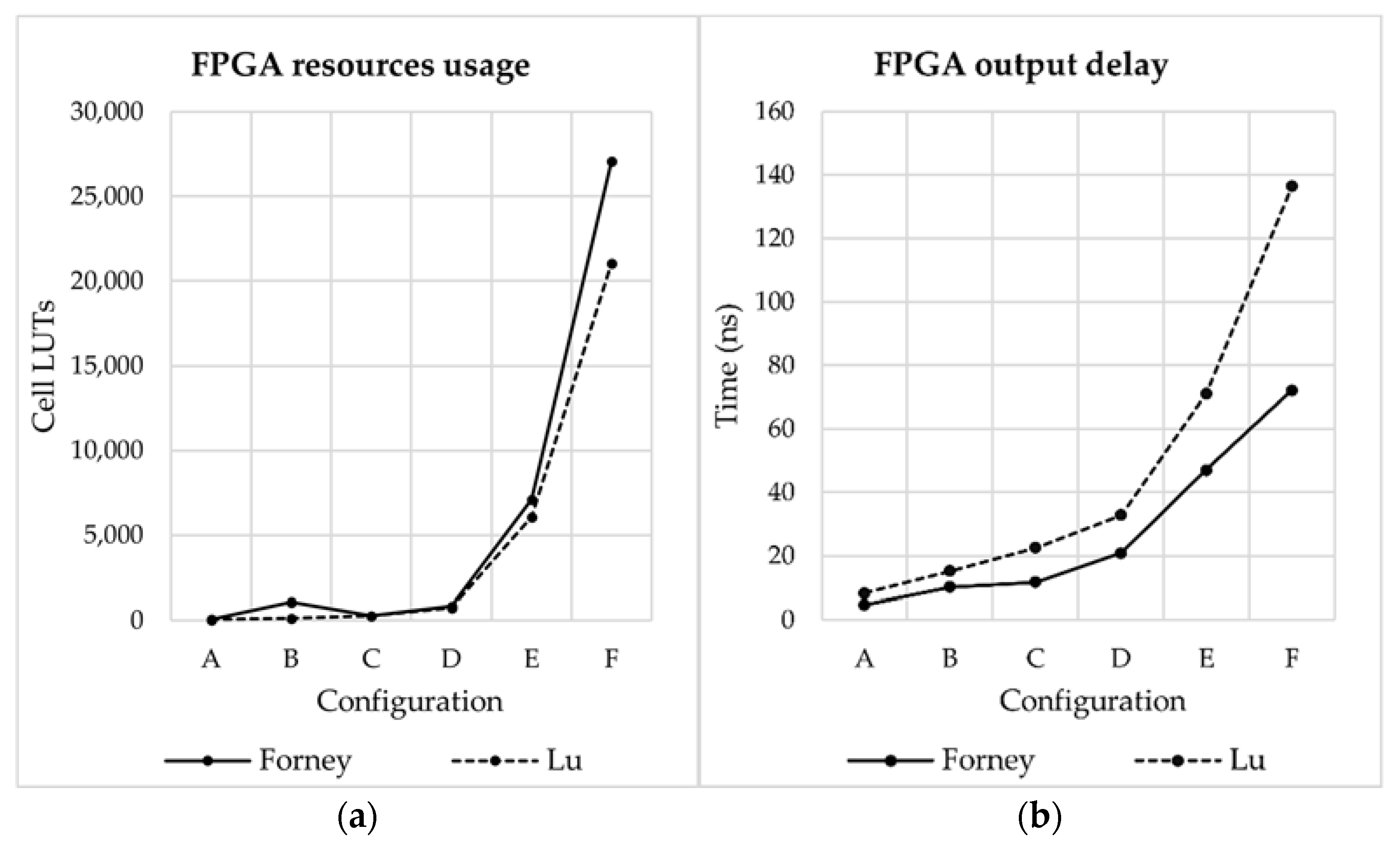
| System Configuration | Forney | Lu | ||
|---|---|---|---|---|
| Cell LUTs | Time (ns) | Cell LUTs | Time (ns) | |
| A | 56 | 6.7 | 62 | 8.3 |
| B | 163 | 10.2 | 138 | 15.2 |
| C | 263 | 11.7 | 268 | 22.5 |
| D | 828 | 20.8 | 760 | 32.8 |
| E | 7126 | 47 | 6081 | 71 |
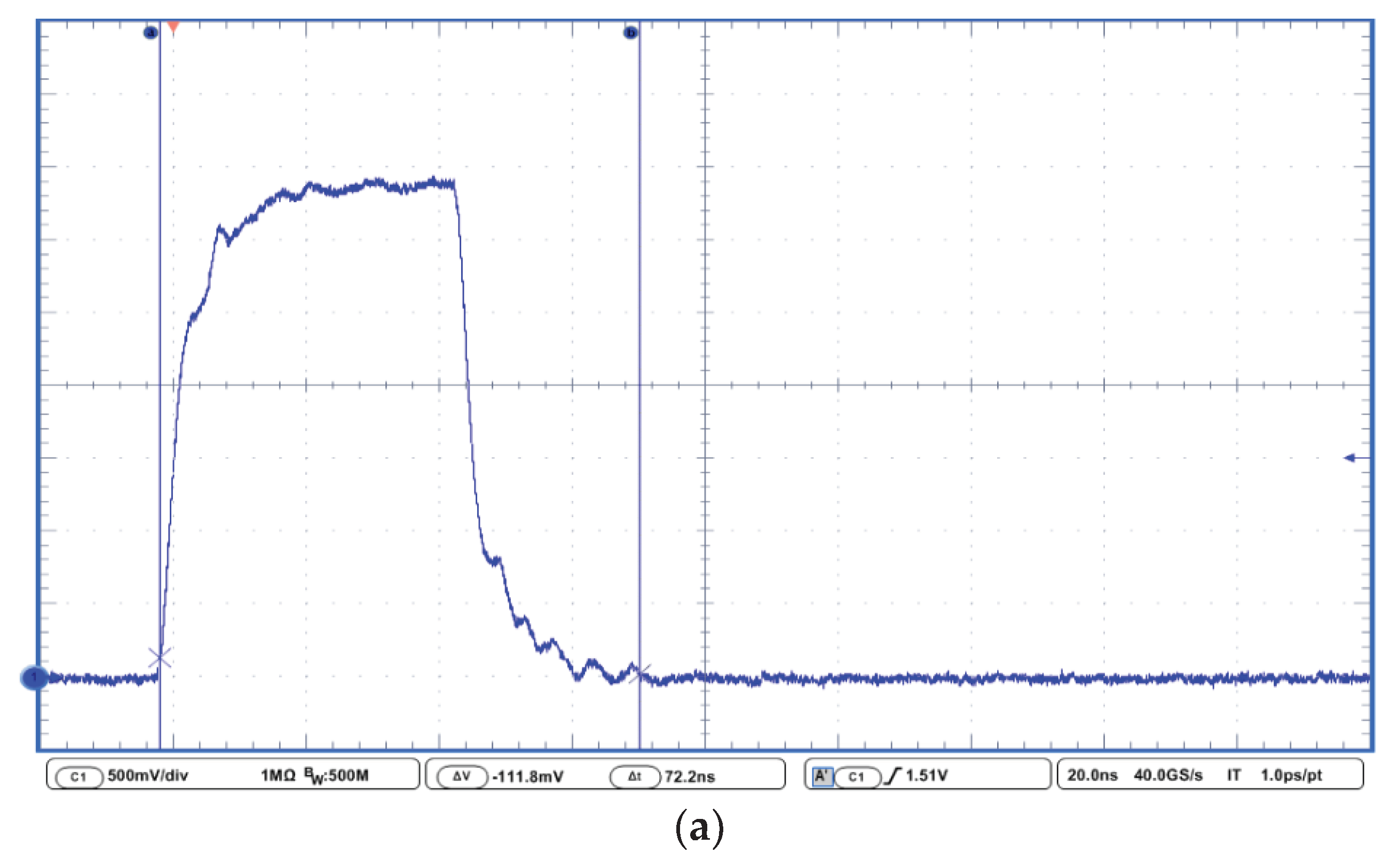
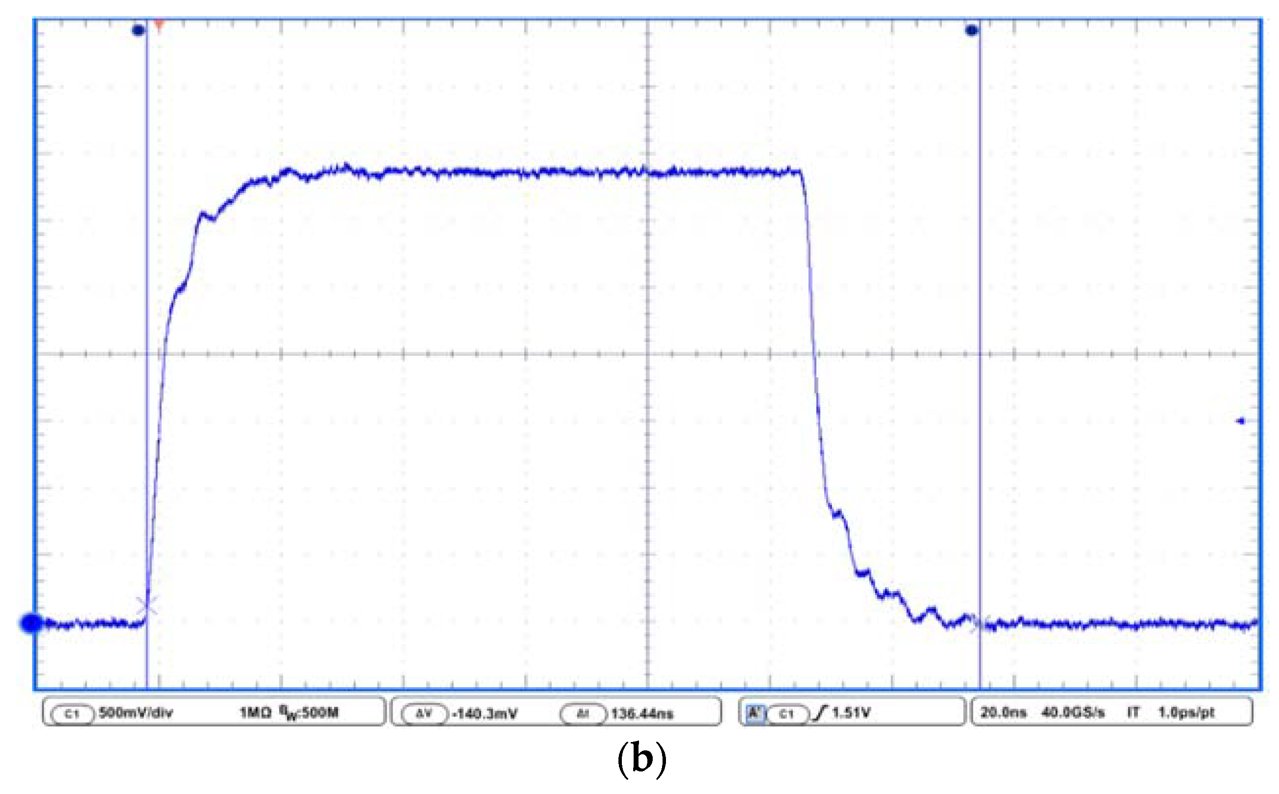
| F | 27,100 | 72.2 | 21,082 | 136.4 |
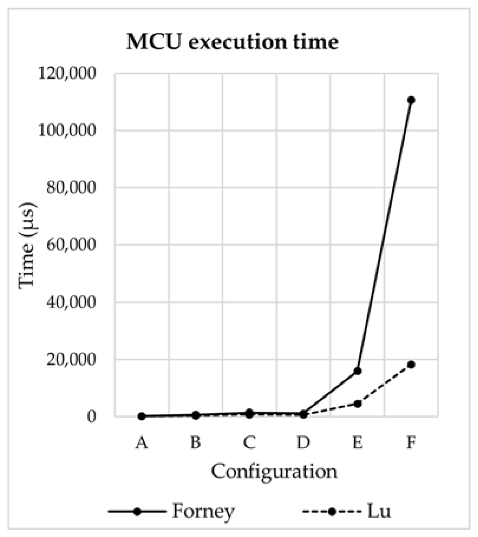
| System Configuration | Forney | Lu |
|---|---|---|
| Time (µs) | Time (µs) | |
| A | 186.1 | 169.8 |
| B | 668.1 | 389.3 |
| C | 1400 | 699.2 |
| D | 1100 | 607.3 |
| E | 15,900 | 4500 |
| F | 110,600 | 18,300 |
© 2020 by the authors. Licensee MDPI, Basel, Switzerland. This article is an open access article distributed under the terms and conditions of the Creative Commons Attribution (CC BY) license (http://creativecommons.org/licenses/by/4.0/).
Share and Cite
Bianchi, V.; Bassoli, M.; De Munari, I. Comparison of FPGA and Microcontroller Implementations of an Innovative Method for Error Magnitude Evaluation in Reed–Solomon Codes. Electronics 2020, 9, 89. https://doi.org/10.3390/electronics9010089
Bianchi V, Bassoli M, De Munari I. Comparison of FPGA and Microcontroller Implementations of an Innovative Method for Error Magnitude Evaluation in Reed–Solomon Codes. Electronics. 2020; 9(1):89. https://doi.org/10.3390/electronics9010089
Chicago/Turabian StyleBianchi, Valentina, Marco Bassoli, and Ilaria De Munari. 2020. "Comparison of FPGA and Microcontroller Implementations of an Innovative Method for Error Magnitude Evaluation in Reed–Solomon Codes" Electronics 9, no. 1: 89. https://doi.org/10.3390/electronics9010089
APA StyleBianchi, V., Bassoli, M., & De Munari, I. (2020). Comparison of FPGA and Microcontroller Implementations of an Innovative Method for Error Magnitude Evaluation in Reed–Solomon Codes. Electronics, 9(1), 89. https://doi.org/10.3390/electronics9010089