Article

Precision and Stability in Hydrostatic Transmissions with Robust H Control Under Parametric Uncertainties

1
Department of Production Engineering, National Institute of Technology, Tiruchirappalli 620015, Tamil Nadu, India
2
AAU Energy, The Faculty of Engineering and Science, Section for Mechatronic Systems, Aalborg University, DK-9220 Aalborg East, Denmark
3
Department of Mechanical Engineering, Smt. Kashibai Navale College of Engineering, Pune 411041, Maharashtra, India
4
NLC India Limited, Chennai 600001, Tamil Nadu, India
5
Department of Mechanical Engineering, Indian Institute of Technology (Indian School of Mines), Dhanbad 826004, Jharkhand, India
*
Author to whom correspondence should be addressed.
J. Exp. Theor. Anal. 2025, 3(2), 14; https://doi.org/10.3390/jeta3020014
Submission received: 13 March 2025 / Revised: 26 April 2025 / Accepted: 2 May 2025 / Published: 13 May 2025

Abstract

:
Hydrostatic transmissions are essential in applications demanding variable torque and speed, such as mining and agricultural machinery, due to their compact design, high power-to-weight ratio, and efficient variable speed control. Despite these advantages, their inherent nonlinearities and susceptibility to parametric uncertainties pose significant challenges for precise motion control. This study presents a comparative analysis of classical PID and robust H-infinity controllers for regulating the speed of hydraulic motors under varying torsional loads. A linearized uncertain system model is developed using upper Linear Fractional Transformations (LFTs) to capture key parametric uncertainties. A simplified H-infinity controller is designed to robustly manage system dynamics, particularly addressing phase lags induced by uncertain loads. Simulation results demonstrate that the H-infinity controller offers superior performance over the PID controller in terms of stability, disturbance rejection, and robustness to load fluctuations. This work contributes a practically viable robust control solution for improving the reliability and precision of electro-hydraulic systems, particularly in demanding, real-world environments.

1. Introduction

Hydraulic motors are essential in both industrial and mobile machinery, converting hydraulic energy into mechanical motion. These systems are critical in applications requiring high power density and precise control, such as construction equipment and robotics. Effective speed control of hydraulic motors is crucial for optimizing performance, enhancing energy efficiency, and maintaining system stability. However, this task is complicated by the inherent nonlinearities, uncertainties, and disturbances in hydraulic systems.
The role of pumps, particularly axial piston pumps, in hydraulic systems has become increasingly important due to their pressure control applications [1]. These pumps have a number of features that make them useful, such as providing regulated flow based on consumer demand, which leads to increased efficiency, and minimising oil temperature with controlled pressure. The variable displacement axial piston pump, in combination with various valves such as servo or proportional valves, provides modern hydraulic systems with efficiency and ease of operation. The static and dynamic characteristics of these pumps are modelled in sophisticated hydraulic control systems [2]. Hydraulic power supplies that are monitored, as well as hydrostatic transmission drives, are two key areas in which these pumps are used frequently. Its ability to vary its displacement, as well as its high power to weight ratio, make it a more desirable component for controlling systems that require the most power [3]. They are relatively simple and reliable in terms of design; however, their main key feature is the ability to vary the displacement at the output.
Several studies have explored control strategies for hydraulic motor speed systems. As Hu and Zhang [4] presents a fuzzy adaptive PID control algorithm for valve-controlled hydraulic motors under fluctuating loads. Model identification and harmonic superposition defined system dynamics. Co-simulation showed over 50% error reduction and 0.04 s faster rise time. Experimental results confirmed improved accuracy with average error reductions of 1.68–2.68 rev/min. Wang et al. [5] used gray theory and PID to achieve <5% overshoot but didn’t fully address load fluctuations. Kumar et al. [6] employed fuzzy adaptive PID with 25 rules, controlling speed error to <10 rev/min, yet used speculative load ranges. Chen et al. [7] developed a shunt collector valve-based system with <5 rev/min error but faced pressure losses under high load differences. Zagar et al. [8] proposed an improved synchronous controller in SIMULINK, though untested experimentally. Goman et al. [9] found neural network PID excels in anti-load disturbances, but lacked experimental validation.
Meanwhile, in order to complete the task of controlling a hydraulic component such as a hydro-motor, it is necessary to use control methods that can be quite effective, such as PID [10,11], fuzzy [12,13], MPC [14], neural networks [15], and so on. Because of its unique characteristics, such as simple structuring, ease of execution, and comprehensive analytical analysis, PID is widely used in hydraulic systems. The efficient tuning of the three adaptable gains, the proportional gain K p , integral gain K i , and derivative gain K d , is the most important part of PID control. PID, on the other hand, is capable of dealing with systems that have linear attributes but is incapable of dealing with systems that have nonlinear behaviour on their own.
H a robust type control has been found to be another viable modelling option which yields quite satisfactory results for the system which has high nonlinearities. The position control of an Electro-hydraulic servo systems (EHSS) having parametric uncertainties has been carried out using linear matrix inequalities approach [16]. The mathematical model considering nonlinear features is devised for a hydraulic linear actuator along with proportional valve. In order to take care of the feedback issue, an analytical model has been proposed. The devised strategy has been tested both experimentally and through simulations as well and it has been observed that the simulation results suitably justify the test results. The simulation results also showed the robust feature of the projected controller under the condition of the variation in the load force and system parameters. Guo et al. [17] have proposed a H position controller having feedback features in order to enhance and eliminate the disturbance in an EHSS arising out of parameters uncertainty. The model is expressed in the form of state–space equation having linear structure while using fractional transformation. In order to match the similar conditions observed in case of EHSS, the simplified form of the generalised model has been developed. The consistency observed in both the test and simulation results justifies the robust nature of the devised model. The suitability of the proposed controller can also be highlighted while comparing against PI control when tested for a preferred higher band width and under the situation when the actuator is working under full capacity during externally applied loading circumstances. Pukpinyo and Assawinchaichote [18] have proposed reconfigurable speed controller dedicated for a permanent-magnet synchronous motor (PMSM) having uncertainties as per control theories focussing of H along with Takagi Sugeno (TS) fuzzy controller. The prime concern in the designing of the controller has been the explicit use of both upper and lower limits, pertaining to PMSM parameters. Based on the results obtained, it can be asserted that the designed controller gives significantly superior performance along with features such as minimum error and swift and quick response in contrast to the TS controller. Papkollu et al. [19] have used two controls i.e., PID in association with H for designing the suspension of a scale model of a passenger car having force actuator which is having nonlinear characteristics. A contrast is being carried out depicting the performance of the twin controllers. The simulation study on the real time non-linear model involving the suspension has been carried out in order to validate the control strategy. A control system designed having robust features is being executed on a brake actuator related to an advanced car in [20]. In order to achieve superior performance, an H controller is selected to execute the task. This permits exceptional rejection of disturbance amidst necessitating minimum computational requirements. For experiencing the real time environment, a scaled model having similar features has been designed and finally the uncertainties linked with the parameter have also been accounted for finding out the stable controller. Breganon et al. [21] have proposed the design involving triple controllers i.e., H , PID and Fuzzy for implementing it for a Stewart platform. The model of the actuator has been developed via feeding input voltage in the form of steps to an electric motor and determining its displacement in the three axes of the motors through encoders which are being coupled to it. It has been observed that the performance of the three controllers have been found to be quite satisfactory while dealing with controlling of the position and angular orientation pertaining to the Stewart platform. Fuzzy PID implemented designed to control the piston actuator for the off-road vehicle [22,23]. A basic insight into the various nonlinear control approaches available for dealing with an electrohydraulic system have been projected by [24] Guo and Jiang which has been handy in understanding the designing as well as real time application of customized controllers intended for specified tasks. Adaptive Control techniques, on the other hand, dynamically adjust to changing system parameters, ensuring consistent performance in environments with varying dynamics. These controllers offer high robustness and good disturbance rejection, striking a balance between adaptability and implementation complexity [25]. For systems with significant nonlinearities and uncertainties, Sliding Mode Control (SMC) presents a compelling solution due to its high robustness and strong disturbance rejection capabilities. However, the associated high computational complexity and tuning difficulty can be challenging. Despite these drawbacks, SMC remains a powerful approach when stringent control precision is required [26].
Among these advanced control strategies, H Control emerges as a particularly suitable solution for hydraulic motor speed regulation. It provides very high robustness and excellent disturbance rejection, making it ideal for applications that demand robust stability and high precision [27]. While H Control involves significant computational complexity and intricate tuning processes, its ability to deliver fast response times and superior performance in uncertain environments [28] makes it a strong candidate for addressing the shortcomings observed with PID control. By leveraging H Control, a more reliable and adaptable system can be achieved, ensuring precise trajectory tracking and enhanced overall system performance. For instance, the effectiveness of adaptive regulation and integrated control strategies in enhancing system efficiency and robustness [29]. Additionally, the application of dual-mode controllers has shown promising results in maintaining robust stability across varying operational conditions [30]. A robust adaptive H control scheme is developed by Wang et al. [31] to simultaneously achieve load tracking and multi-motor synchronization in a multi-motor servomechanism (MMS). These findings underscore the importance of incorporating contemporary research to contextualize and validate the current study, ensuring it aligns with the latest technological and environmental standards.
This paper investigates speed sensing in hydrostatic transmission systems under parametric uncertainties, focusing on speed control of a hydraulic motor using both PID and robust H controllers in a closed-loop hydrostatic transmission system. The pump is regulated through feedback control, while an artificial load is introduced by varying the cracking pressure of a proportional pressure relief valve. Comparative analysis demonstrates that the H controller significantly outperforms the PID controller in terms of response time and dynamic performance, ensuring superior stability and robustness. This advantage is particularly beneficial in rolling mills, where high torque demand is required for material thickness reduction. The high power-to-weight ratio of hydraulic transmissions makes them an optimal choice for driving rollers in such applications. The findings underscore the potential of H control in enhancing industrial system performance, particularly in demanding environments requiring precise speed regulation.

2. Hydraulic System Modeling

The modelling for the proposed system is done in MATLAB-Simulink 2021b. The following are the assumptions that are considered when modelling:
  • The fluid’s compressibility is taken into account.
  • The variation in the valve opening associated with the valve is linear as a function of the pressure differential.
  • The inertial as well as the frictional spring loads acting upon the valve are not taken into account.
  • The effect arising as a result of flow force is ignored.
  • The assumption of constant leakage coefficients is made in this study.
The simplified circuit diagram of the hydrostatic transmission system is shown in Figure 1. The parameter values used in simulation are shown in Table 1. The pump displacement setting, D p , is controlled by a hydraulic servo system and the pump is driven by an electric motor with constant angular velocity ω p . The frequency of the servo system is much higher than the natural frequency of the hydrostatic transmission system, hence it is safe to model the pump displacement ϵ p ( s ) as a first order system.

2.1. Pump Servo Dynamics

The pump servo dynamics can be represented by the following equation:
ϵ p ( s ) = K p τ p s + 1 · I ( s )
where:
  • K p is the servo gain of the pump,
  • τ p is the time constant of the pump servo system,
  • I ( s ) is the input current to the servo.
This equation describes how the displacement of the pump is controlled by the input current I ( s ) , where the servo gain K p and the time constant τ p influence the system dynamics.

2.2. Pressure Dynamics

The pressure dynamics in the system, which account for the leakage flow and the charge flow Q ˙ c h a r g e , are derived from the continuity equation. The pressure deviation Δ p is governed by the following equation:
d ( Δ p ) d t = β e V t D p ω p C t Δ p D m ω m + Q ˙ c h a r g e
where:
  • Δ p is the pressure deviation,
  • D p ω p is the pressure generated by the pump,
  • C t Δ p represents the leakage flow,
  • D m ω m is the motor flow,
  • Q ˙ c h a r g e is the charge flow that offsets the leakage.
Taking the Laplace transform (assuming zero initial conditions) gives:
Δ p ( s ) = β e V t s + β e C t D p ω p D m ω m ( s ) + Q ˙ c h a r g e ( s )

2.3. Motor Dynamics

Applying Newton’s second law of motion to the hydraulic motor shaft gives the following torque balance equation:
J m s ω m ( s ) = D m Δ p ( s ) B m ω m ( s )
where:
  • J m is the moment of inertia of the motor,
  • B m is the viscous damping coefficient of the motor,
  • ω m ( s ) is the angular velocity of the motor.
Rearranging this equation to express Δ p ( s ) in terms of ω m ( s ) :
Δ p ( s ) = ( J m s + B m ) D m ω m ( s )

2.4. Combining Pressure and Torque Equations

Substituting the expression for Δ p ( s ) into the pressure equation gives:
( J m s + B m ) D m ω m ( s ) = β e V t s + β e C t D p ω p D m ω m ( s ) + Q ˙ c h a r g e ( s )
After multiplying it by D m and rearranging, we obtain:
ω m ( s ) = β e D m D p ω p ( J m s + B m ) ( V t s + β e C t ) + β e D m 2 1 + Q ˙ c h a r g e ( s ) D p ω p
This equation now incorporates the effect of the charge flow Q ˙ c h a r g e ( s ) , which modifies the overall pressure balance in the system.

2.5. Hydraulic System Dynamics

The system dynamics can be expressed as a second-order system, which reflects the hydraulic resonance and damping behavior. The general form of the characteristic equation is:
ω h 2 s 2 + 2 δ h ω h s + ω h 2 = 0
where:
  • ω h is the natural frequency of the hydraulic system,
  • δ h is the damping ratio of the system.
These parameters govern the transient and steady-state behavior of the hydraulic system. The natural frequency and damping ratio are given by:
ω h = β e ( D m 2 + B m C t ) J m V t
δ h = B m V t + J m β e C t 2 J m V t ω h

2.6. Incorporating Pump Servo Dynamics

When incorporating the dynamics of the pump servo system, we substitute D p ( s ) = ϵ p ( s ) , where ϵ p ( s ) is given by the first-order system:
ω m ( s ) = K p β e D m ω p ( J m s + B m ) ( V t s + β e C t ) + β e D m 2 · 1 τ p s + 1 · I ( s )
Here:
  • K p is the pump servo gain,
  • τ p is the time constant of the pump servo system.
This equation now fully incorporates the effects of the pump servo dynamics on the motor angular velocity ω m ( s ) .

2.7. Final Transfer Function

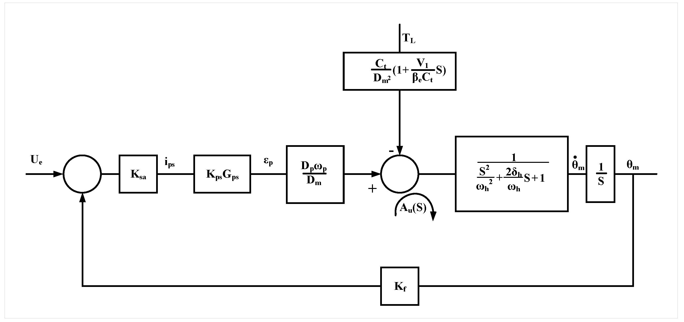
The final transfer function, which relates the input current I ( s ) to the motor’s angular velocity θ ˙ m ( s ) , includes an integrator for position control and a lead compensator to account for the pump servo dynamics. The final transfer function is:
θ ˙ m ( s ) Δ i p ( s ) = K v 1 + s ω p s s s 2 ω h 2 + 2 δ h ω h s + 1
where:
  • K v = K p β e D m ω p D m is the system gain,
  • ω p s = 1 τ p is the servo cutoff frequency,
  • ω h and δ h define the hydraulic dynamics.
The transfer function represents the relationship between the input current and the motor’s angular velocity, incorporating all the dynamic elements of the pump servo system, pressure dynamics, and motor behavior, as shown in Figure 2.

3. Simulations Result

3.1. PID Control of the Closed Loop System

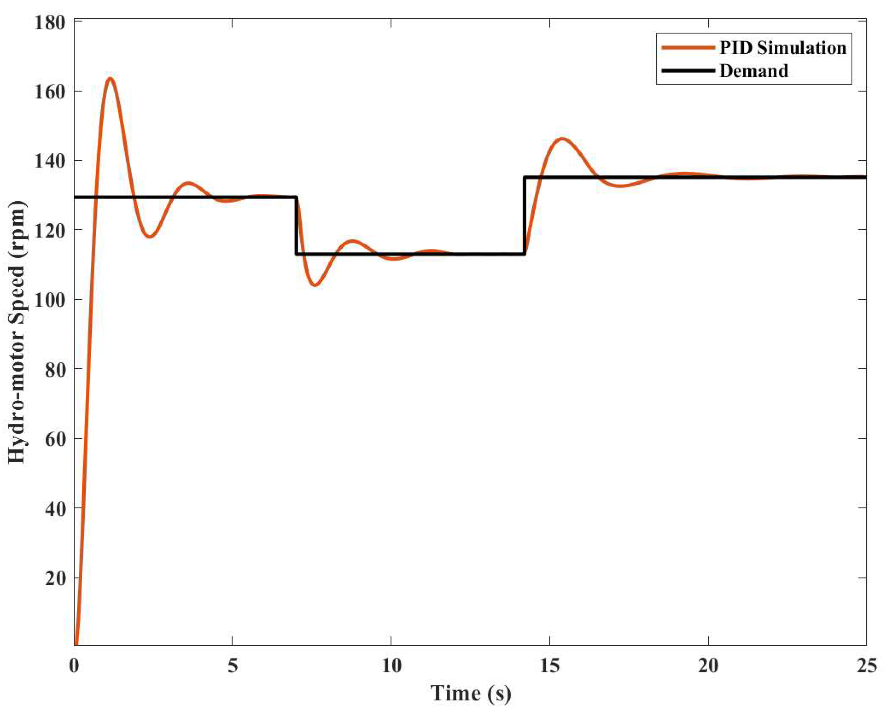
The response of the hydraulic motor speed in relation to the Hydrostatic Transmission (HST) has been simulated and traced in Figure 3. The model is designed to ensure that the rotational speed of the motor continuously tries to match the excitation step signal. Specifically, whenever the motor’s RPM falls below the desired threshold, the pump adjusts the transmission’s basic or primary setting. This triggers a feedback mechanism, controlled by PID, which leads to a change in the pump’s capacity by altering the swash plate angle. The feedback is activated by monitoring the motor’s rotational speed, which is influenced by the load applied, adjusted by modifying the settings of the Pressure Relief Valve (PRV). The excitation step signals are superimposed with the motor’s response speed in various step signal zones. The permissible range for the motor’s rotational speed has been determined for the model.
The dynamic behavior of the system was considered, highlighting the effect of step-type signals for RPM, overlapped by the hydraulic motor. This is done by adjusting the motor’s feedback signal and the resulting changes in the variable pump’s capacity. This process accounts for both the presence and absence of error, as well as its compensation, as demonstrated in the first phase (up to approximately 7 s) as shown in Figure 3. The same phenomenon is observed in the other steps, where the motor’s flow adjustment is determined by the variable displacement pump’s capacity, as illustrated in the second phase (approximately 7–15 s) and the third phase (after 15 s) of the graph shown in Figure 3.
The primary goal was to optimize the PID-controlled hydraulic transmission model with variable adjustments. The optimization was aimed at two objectives: minimizing fluctuations in the motor’s rotational speed under variable loads and reducing unnecessary flow discharge through the pump valve. However, due to the limitations of the PID control in fully matching the demand, and after an extensive review of the literature, an H-Infinity controller was proposed as a more effective solution for controlling the system.

3.2. H Controller

In hydraulic motor speed control, various control strategies are utilized to achieve optimal performance. Among these, PID controllers are widely favored due to their simplicity, ease of implementation, and fast response times, making them well suited for systems with minimal variations. However, as observed in Figure 3, the PID-controlled system fails to accurately track the desired trajectory, highlighting its limitations. While PID controllers offer low computational complexity, their poor robustness and inability to adapt to system uncertainties reduce their effectiveness in more complex and dynamic environments [32]. This necessitates the exploration of more advanced control strategies to enhance tracking accuracy and overall system performance.
To overcome these limitations, more advanced control strategies, such as Fuzzy Logic Control (FLC), Adaptive Control, Sliding Mode Control (SMC), and H Control, offer improved performance by enhancing robustness and disturbance rejection capabilities. FLCs provide a moderate level of robustness and are particularly useful for nonlinear systems with imprecise models. Their ability to handle ambiguity and uncertainty makes them a viable option when precise system modeling is challenging. However, their computational complexity and tuning requirements may limit their practicality in some applications [33]. Table 2 shows the comparison of various control methods.

3.3. H Control Design for the Hydraulic Motor System

To design an H controller for the hydraulic motor system, we need to focus on minimizing the worst-case effect of disturbances and uncertainties on the system. The aim is to minimize the H norm of the transfer function, which represents the sensitivity of the output to the disturbance.

3.3.1. System Representation

The hydraulic system represented in state-space form as:
x ˙ ( t ) = A x ( t ) + B u ( t )
y ( t ) = C x ( t ) + D u ( t )
where:
  • x ( t ) = ω m Δ p : State vector,
  • u ( t ) = ω p : Control input (pump angular velocity),
  • w ( t ) = T L : Disturbance input (external load),
  • y ( t ) = ω m : Output (motor angular velocity),
The state-space matrices A, B, C, and D describe the system dynamics, as shown:
A = B m J m D m J m D m β e V t C t β e V t B = 0 D p β e V t B w = 1 J m 0
C = 1 0 D = 0 D w = 0
These matrices represent the dynamics of the hydraulic motor system.

3.3.2. Plant Model

The plant model P ( s ) defines the relationship between the disturbance input w, control input u, and outputs z (performance output) and y (measured output). In the frequency domain, the system is described as:
z y = P ( s ) w u = P 11 ( s ) P 12 ( s ) P 21 ( s ) P 22 ( s ) w u
where:
  • z is the performance output,
  • y is the measured output,
  • w is the disturbance input,
  • u is the control input.
The terms P 11 ( s ) , P 12 ( s ) , P 21 ( s ) , and P 22 ( s ) are submatrices of the generalized plant P ( s ) . These submatrices define the relationships between the inputs and outputs of the generalized plant.

3.3.3. Performance Weights

Performance weights are used to shape the closed-loop response. Common weights include:
  • Sensitivity weight W S ( s ) : Ensures good disturbance rejection and tracking.
  • Control effort weight W U ( s ) : Limits the control input magnitude.
  • Complementary sensitivity weight W T ( s ) : Ensures robustness to model uncertainties.
These weights shape the system performance, since they are used in the design of the sensitivity and complementary sensitivity functions.

3.3.4. Sensitivity and Complementary Sensitivity Functions

The sensitivity function S ( s ) and complementary sensitivity function T ( s ) are defined as:
S ( s ) = ( I + G ( s ) K ( s ) ) 1
T ( s ) = G ( s ) K ( s ) ( I + G ( s ) K ( s ) ) 1
where:
  • G ( s ) is the plant transfer function,
  • K ( s ) is the controller transfer function.
These functions describe the system’s ability to reject disturbances and its robustness to model uncertainties.

3.3.5. The H Control Problem

The H control problem is formulated as minimizing the norm of the transfer function from the disturbance w to the performance output z. The problem is written as:
min K ( s ) T z w ( s )
where T z w ( s ) is the closed-loop transfer function from the disturbance input w to the performance output z. The objective is to minimize the worst-case disturbance effect by optimizing the controller K ( s ) .

3.3.6. State Feedback H Controller Design

To design a state feedback controller u ( t ) = K x ( t ) , we use the Riccati equation. This step is crucial in determining the state feedback gain K.
The Riccati equation for state feedback control is:
A T X + X A X ( B B T γ 2 B w B w T ) X + C T C = 0
where:
  • X is the solution to the Riccati equation,
  • γ is the performance bound, ensuring that the H norm of the transfer function is below a threshold,
  • K = B T X is the state feedback gain.
This equation balances the performance and robustness criteria by adjusting the state feedback gain.

3.3.7. Output-Feedback H Controller Design

For an output-feedback controller, we solve a set of two Riccati equations. The equations are used to determine the controller K ( s ) that achieves the desired performance.
The first Riccati equation is:
A X + X A T X ( C T C γ 2 C w C w T ) X + B B T = 0
The second Riccati equation is:
A T Y + Y A Y ( B B T γ 2 B w B w T ) Y + C T C = 0
where:
  • X and Y are the solutions to the Riccati equations,
  • The controller K ( s ) is derived from X and Y.
These two equations allow us to calculate the output-feedback controller that minimizes the effect of disturbances.

3.3.8. Sensitivity and Complementary Sensitivity Analysis

The sensitivity and complementary sensitivity functions are key for analyzing the robustness and performance of the closed-loop system. The sensitivity function S ( s ) and complementary sensitivity function T ( s ) are defined as:
S ( s ) = ( I + G ( s ) K ( s ) ) 1
T ( s ) = G ( s ) K ( s ) ( I + G ( s ) K ( s ) ) 1
where:
  • S ( s ) measures the system’s ability to reject disturbances,
  • T ( s ) measures the system’s robustness to model uncertainties.
These functions are essential for understanding the trade-off between performance and robustness in the closed-loop system.

3.3.9. Closed-Loop Transfer Functions

The closed-loop transfer functions are computed to describe the system’s response to various inputs:
  • From disturbance w to performance output z:
    T z w ( s ) = P 11 ( s ) + P 12 ( s ) K ( s ) ( I P 22 ( s ) K ( s ) ) 1 P 21 ( s )
  • From disturbance w to measured output y:
    T y w ( s ) = ( I P 22 ( s ) K ( s ) ) 1 P 21 ( s )
  • From control input u to performance output z:
    T z u ( s ) = P 12 ( s ) K ( s ) ( I P 22 ( s ) K ( s ) ) 1
These transfer functions represent the system behavior and how the controller modifies the outputs in response to disturbances and control inputs.

3.3.10. Performance Criteria

The performance criteria for the H controller are:
W S ( s ) S ( s ) < 1
W U ( s ) K ( s ) S ( s ) < 1
W T ( s ) T ( s ) < 1
These criteria ensure that the system satisfies the performance and robustness requirements. They guarantee that the system can effectively reject disturbances and remains robust to model uncertainties.

3.3.11. Final Control Implementation

Once the H controller K ( s ) has been designed, it is implemented in the hydraulic motor system. The control law is:
u ( t ) = K ( s ) y ( t )
where y ( t ) is the measured output (motor speed ω m ).

3.4. Performance Metrics

The H-infinity controller design for a hydraulic motor system focuses on achieving robust performance and disturbance attenuation. The controller is designed to minimize the H-infinity norm of the transfer function from the disturbance to the controlled output, ensuring the system can handle uncertainties and external disturbances effectively. The state space form of H-infinity controller K ( s ) obtained as:
K A = 1.824 7.201 × 10 6 0 0 5.777 × 10 13 5.124 × 10 5 1.033 × 10 14 1.354 × 10 12 2.889 × 10 12 3.995 × 10 23 0.01 7.721 × 10 14 8 6.382 × 10 26 8.235 × 10 15 100
K B = 0 1.821 × 10 15 4 4.115 × 10 17
K C = 1.142 × 10 5 1.607 × 10 6 2.042 × 10 5 2676
K D = 0
The achieved γ value:
γ = 1.4285
The H-infinity norms of the sensitivity functions:
S = 1.0061
T = 0.9986
C S = 999.992
The parameter γ = 1.4285 is a crucial value in the H-infinity control design, representing the upper bound on the H-infinity norm of the closed-loop transfer function. The value ensures that the system maintains robust performance and stability under the designed controller.
The sensitivity function S ( s ) represents the system’s response to disturbances. The H-infinity norm of the sensitivity function, S = 1.0061 , indicates the maximum gain of S ( s ) across all frequencies. A value close to 1 suggests that the system effectively rejects disturbances at low frequencies, ensuring robust performance. The Bode plot in Figure 4 shows that the sensitivity function has low magnitude at low frequencies, confirming effective disturbance rejection.
The complementary sensitivity function T ( s ) represents the system’s response to measurement noise. The H-infinity norm of the complementary sensitivity function, T = 0.9986 , indicates the maximum gain of T ( s ) across all frequencies. A value close to 1 suggests that the system effectively attenuates high-frequency noise, maintaining stability. The Bode plot in Figure 5 shows that the complementary sensitivity function has low magnitude at high frequencies, confirming effective noise attenuation.
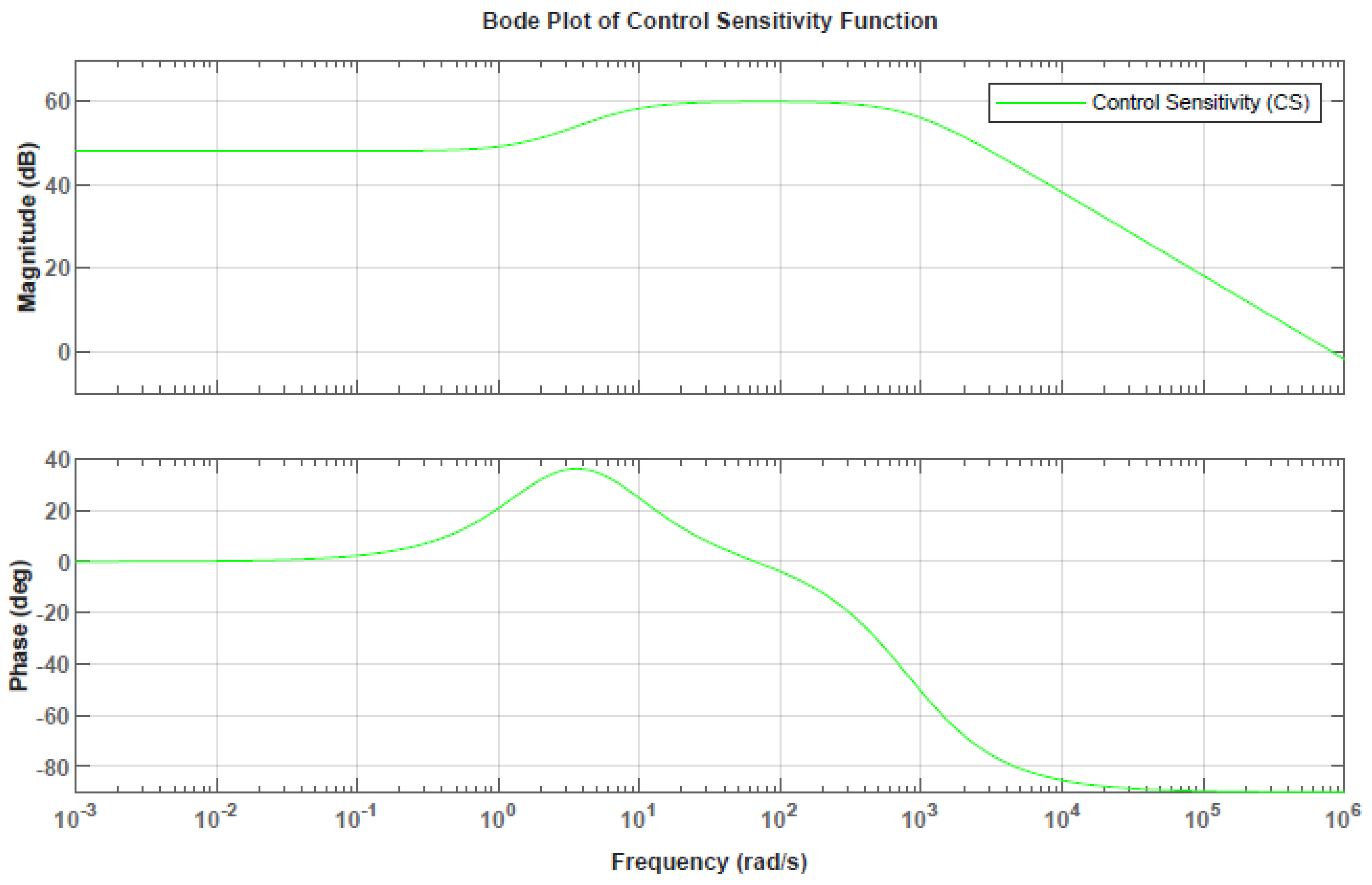
The control sensitivity function C S ( s ) represents the system’s response to control input. The H-infinity norm of the control sensitivity function, C S = 999.992 , is significantly higher, indicating that the system requires substantial control effort to maintain performance. This high value suggests that the controller is highly responsive, ensuring precise control of the hydraulic motor system.
The performance matrix P ( s ) and the weighting functions W 1 ( s ) and W 2 ( s ) are critical in shaping the sensitivity functions. The chosen values for these weighting functions ensure that the sensitivity function S ( s ) has low gain at low frequencies, while the complementary sensitivity function T ( s ) has low gain at high frequencies. The balance is essential for achieving robust performance and stability.
The sensitivity analysis demonstrates that the H-infinity controller for the hydraulic motor system effectively balances disturbance rejection, noise attenuation, and control effort. The H-infinity norms of the sensitivity functions confirm the controller’s ability to maintain robust performance across a wide frequency range. The Bode plots in Figure 4 and Figure 5 provide a visual validation of these characteristics, highlighting the controller’s effectiveness in managing the hydraulic motor system.
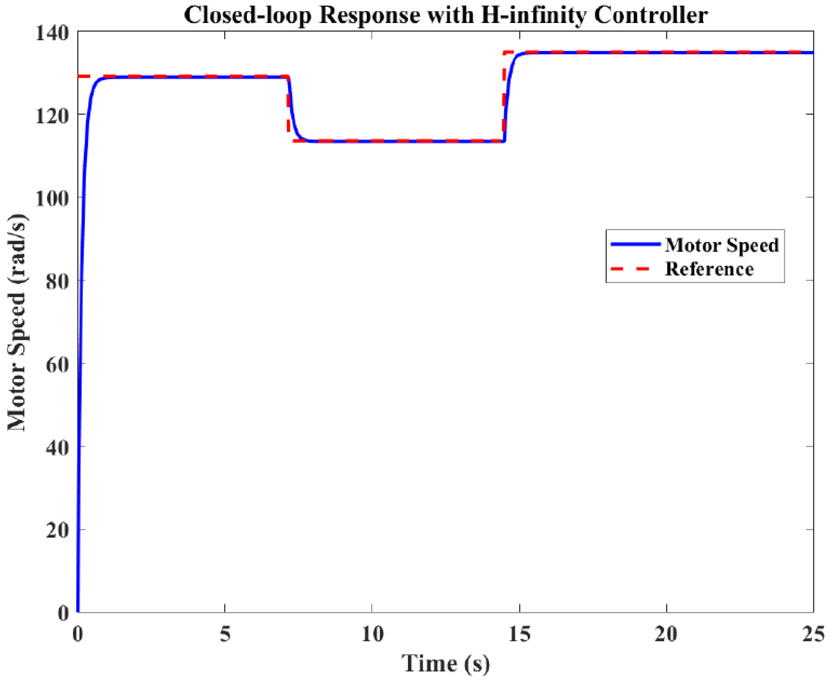
The graph illustrates in Figure 6 the simulation of hydraulic motor speed controlled using an H-infinity controller. The x-axis represents time (0 to 25 s), and the y-axis represents motor speed (0 to 140 rpm). The solid blue line shows the motor speed, while the dashed red line indicates the reference speed. The motor speed closely follows the reference, demonstrating the effectiveness of the H-infinity controller in maintaining the desired speed with minimal deviation and robust performance.

4. System Description

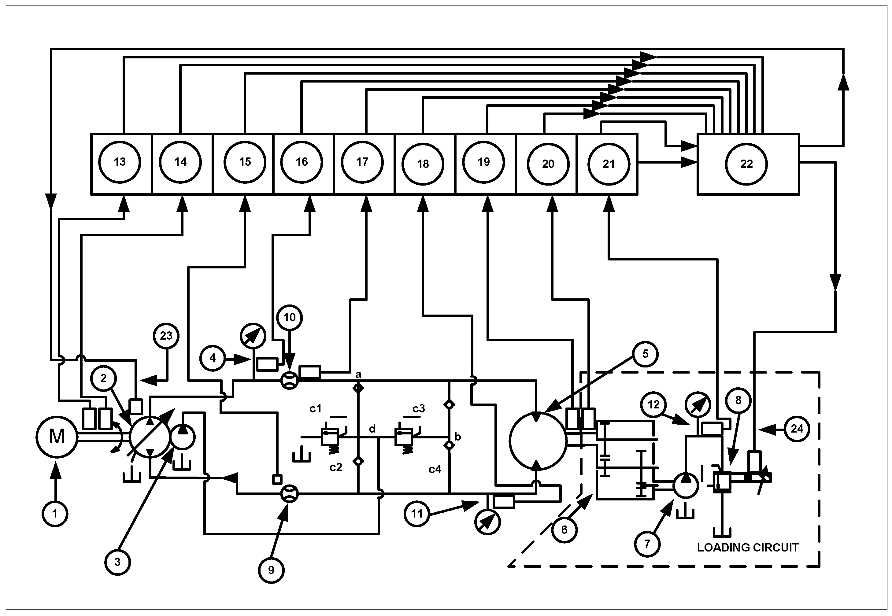
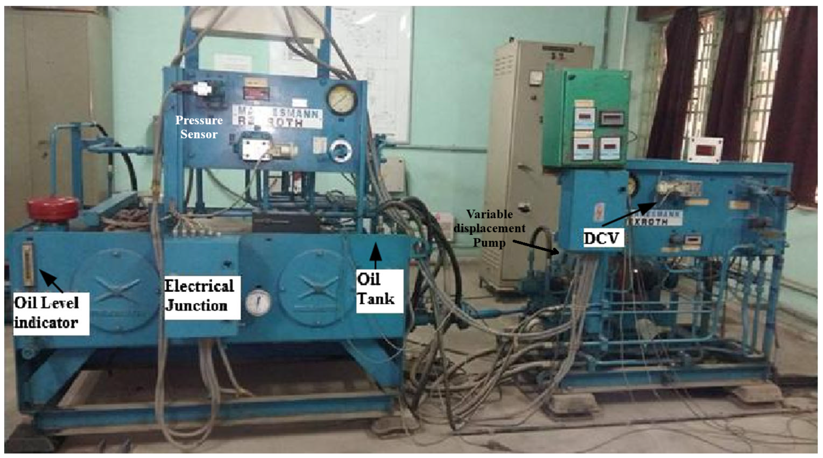
The traditional hydraulic power system is designed in a closed-circuit manner, with an electric motor driving the main pump (Referring Figure 7 and Figure 8). The hydro-motor is powered by a pressurised fluid supplied by a pump. The hydro-motor drives the loading pump through a gear unit (gear ratio 1:20). The proportional pressure relief valve is used to apply the load to the loading pump (PPRV). Table 3 lists the main items used in the physical system, along with their descriptions.

5. Experiment Description

The experiment is carried out using a closed loop hydraulic circuit in the LabView environment with the help of cRIO. With the goal of controlling the PPRV and swash plate of the main pump, an NI cRIO system with 16-Bit Analog Input accepts input from the sensors used in the test setup and an analogue voltage Output Module. The developed LabView programme is run in a real-time situation. The sensors in the test setup are connected to the 0–10 V input modules corresponding to a cRIO. The analogue input and output operations are configured using cRIO’s input and output slots. Through the analogue input module, the signal is made available to the analogue input blog, and the output module accepts the executing signal via the output blog.

6. Results and Discussion

In the pumping zone, PID control is employed to monitor the speed of the hydromotor, ensuring it tracks the reference demand speed. Figure 9 illustrates the simulated and experimental response of the hydromotor speed. The model is designed such that the speed of the hydromotor continuously attempts to match the excitation step signal. If the hydromotor’s speed falls below the desired threshold, the pump adjusts the primary transmission to compensate. The PID control feedback mechanism is activated by sensing the motor’s rotational speed, which is influenced by the load applied through varying the Pressure Relief Valve (PRV) settings.
As the feedback mechanism is triggered, the pump’s capacity is automatically adjusted by modifying the inclination of the swash plate angle. The rotational speed response of the hydromotor is shown superimposed on the excitation step signals in various signal zones.
The permissible range of the hydromotor’s rotational speed has been determined for the model. The dynamic nature of the system is considered, particularly the effect of a step-type speed signal applied to the hydromotor.The parametric values of the PID controller, i.e., K p , K i , and K d , are shown in Table 4. This includes adjustments made in response to feedback, compensating for errors and ensuring no errors persist. The curves in Figure 9 demonstrate this behavior. As observed in the PID curve plots of the graph, a similar trend evident in other steps, where the hydro motor response closely overlaps. This indicates that flow adjustment is primarily governed by the capacity of the variable displacement pump. However, a noticeable error persists in meeting the demand, suggesting limitations in the system’s dynamic response and control precision. The first overshoot occurs at around t = 2.5 s, where the PID controller exceeds the demand speed, reaching approximately 165 rpm before settling. A second overshoot is observed at t = 16 s, where the system peaks around 150 rpm instead of stabilizing immediately at the reference speed. The maximum steady-state error occurs around t = 10 s, where the experimental response deviates significantly from the demand profile, with an error of approximately 10 rpm. The PID controller is not able to achieve accurate trajectory tracking, particularly during transient phases, leading to oscillations and steady-state errors. This suggests the need for exploring alternative control strategies such as adaptive or model predictive control to improve performance.
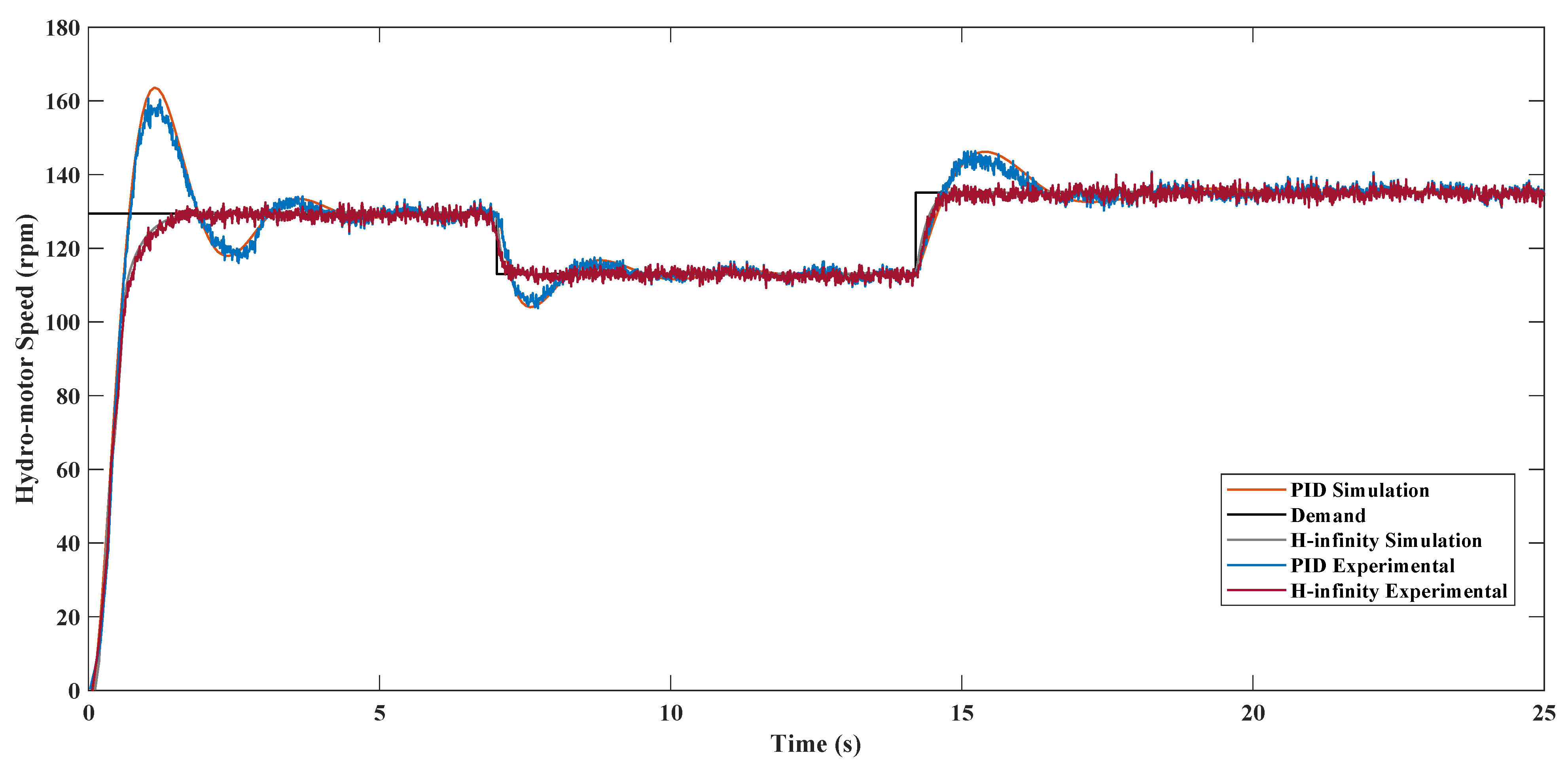
To achieve optimal performance, the objective is to enhance the PID-controlled hydraulic transmission model by minimizing speed fluctuations under varying loads and reducing excessive flow discharge through the pump valve. However, due to the inherent limitations of PID control in accurately matching the demand, the need for a more sophisticated control framework became evident. A mathematical model capturing the essential dynamics of the system was first developed to support this transition. The accuracy of this model is crucial, as it forms the foundation for effective control design. To facilitate parameter identification and ensure reliable controller evaluation, a closed-loop configuration was used. Figure 10 showcases a comparative performance graph of hydro-turbine speed (in rad/s) over time, illustrating both simulation and experimental results for the PID and H-Infinity controllers. The reference speed, marked by a dashed black line, serves as the demand trajectory. In designing this trajectory, key performance criteria were emphasized: no overshoot, zero steady-state error, and minimal rise time. The results clearly demonstrate the superior performance of the H-Infinity controller in achieving these objectives, reinforcing its suitability for precision control in dynamic hydraulic systems.
Initially, all data series start at 130 rad/s and remain stable until around 5 s. This stability indicates that both control strategies maintain the system’s initial state effectively. However, initially there is a noticeable increase in hydro-motor speed for both PID and H-infinity simulations, reaching up to around 135 rad/s. This rise suggests that both controllers respond to a change in demand or disturbance, with the H-infinity controller showing a slightly smoother transition compared to the PID controller.
Between 7.15 and 14.5 s, both simulation curves exhibit a sharp drop back to near their initial values of 114 rad/s. This drop indicates a response to a sudden change or disturbance in the system. The H-infinity controller again demonstrates a more controlled and less oscillatory response compared to the PID controller, highlighting its robustness in handling abrupt changes.
From 14.5 to 25 s, another significant rise in speed is observed, bringing the speeds back up towards the previous peak levels. This period showcases the controllers’ ability to adapt to varying conditions. The H-infinity controller maintains a more consistent and stable response, whereas the PID controller shows more fluctuations, indicating potential challenges in maintaining stability under varying loads.
The experimental data, represented by dotted lines, closely follows the simulation results, validating the effectiveness of both control strategies in real-world scenarios. However, the H-infinity experimental data shows a closer match to the demand curve, particularly in terms of speed stability and response time. This alignment underscores the H-infinity controller’s superior performance in managing the hydro-turbine speed, especially under varying torsional loads and parametric uncertainties.
The graph clearly demonstrates that, while both PID and H-infinity controllers are effective in controlling the hydro-turbine speed, the H-infinity controller outperforms the PID controller in terms of stability, robustness, and accuracy. The H-infinity controller’s ability to handle parametric uncertainties and varying loads makes it a more reliable choice for applications requiring precise speed control in hydrostatic transmission systems. This study highlights the importance of selecting appropriate control strategies to ensure optimal performance and stability in complex systems.

7. Conclusions

This study demonstrates the effectiveness of an H controller in enhancing the stability, robustness, and performance of a hydrostatic transmission system (HTS) under parametric uncertainties. Through rigorous comparison with a conventional PID controller, both in simulations and experiments, the results highlight the superior performance of the H controller in aligning with the desired loop shape, ensuring reliable operation even in the presence of uncertainties.
Key performance metrics, including stability and disturbance rejection, confirm that the H controller outperforms the PID controller. While both controllers satisfy nominal and robust stability requirements, only the H controller meets the robust performance criteria. Additionally, the H controller eliminates the need for an anti-windup scheme, reducing implementation complexity compared to the PID controller.
The practical advantages of the H control strategy are particularly evident in industrial applications such as rolling mills and heavy machinery operations, where precise speed regulation is critical. By effectively damping speed oscillations and mitigating the impact of load variations, the H controller enhances both operational comfort and product quality. Furthermore, the closed-loop system exhibits improved energy efficiency compared to the open-loop system, making it a viable solution for applications requiring high power-to-weight ratios and stringent performance standards.
This research underscores the potential of H control strategies to significantly improve the performance of hydraulic transmission systems in real-world industrial scenarios. The demonstrated robustness and enhanced control precision position the H controller as a compelling alternative to traditional PID control methods, paving the way for more efficient and reliable industrial automation solutions.

Author Contributions

Conceptualization, S.K.M., G.W., J.T.J. and J.D.; Methodology, S.K.M., G.W., P.R., J.T.J. and J.D.; Investigation, S.K.M. and J.D.; Visualization, G.W. and P.R.; Writing—review and editing, S.K.M., G.W., P.R. and J.T.J. All authors have read and agreed to the published version of the manuscript.

Funding

This research received no external funding.

Institutional Review Board Statement

Not applicable.

Informed Consent Statement

Not applicable.

Data Availability Statement

The dataset is available on request from the authors.

Acknowledgments

This work was carried out during the course of my Doctoral studies.

Conflicts of Interest

The authors declare no conflicts of interest.

References

  1. Costopoulos, T. Hydraulic and Pneumatic Systems; Symeon Publishing Co.: Athens, Greece, 1992. [Google Scholar]
  2. Kaliafetis, P.; Costopoulos, T. Modelling and simulation of an axial piston variable displacement pump with pressure control. Mech. Mach. Theory 1995, 30, 599–612. [Google Scholar] [CrossRef]
  3. Karkoub, M.A.; Gad, O.E.; Rabie, M.G. Predicting axial piston pump performance using neural networks. Mech. Mach. Theory 1999, 34, 1211–1226. [Google Scholar] [CrossRef]
  4. Hu, K.; Zhang, W. Precise control algorithm of rotational speed of the valve-controlled hydraulic motor under load fluctuating conditions. Sci. Prog. 2024, 107, 00368504241296299. [Google Scholar] [CrossRef]
  5. Wang, W.; Gong, Y.; Bai, X.; Tan, R.; Huang, W. Investigation on operating speed regulation system of mobile straw granulator. Trans. Chin. Soc. Agric. Mach 2021, 52, 186–195. [Google Scholar]
  6. Kumar, N.; Dasgupta, K.; Ghoshal, S.K. Dynamic analysis of a closed-circuit hydrostatic summation drive using bent axis motors. Proc. Inst. Mech. Eng. Part I J. Syst. Control Eng. 2015, 229, 761–777. [Google Scholar] [CrossRef]
  7. Chen, J.; Luo, Y.; Luo, Y. Co-simulation analysis of synchronization control system on agricultural machinery. Sci. Technol. Eng. 2020, 20, 9362–9366. [Google Scholar]
  8. Zagar, P.; Kogler, H.; Scheidl, R.; Winkler, B. Hydraulic switching control supplementing speed variable hydraulic drives. Actuators 2020, 9, 129. [Google Scholar] [CrossRef]
  9. Goman, V.; Oshurbekov, S.; Kazakbaev, V.; Prakht, V.; Dmitrievskii, V. Energy efficiency analysis of fixed-speed pump drives with various types of motors. Appl. Sci. 2019, 9, 5295. [Google Scholar] [CrossRef]
  10. Çetin, Ş.; Akkaya, A.V. Simulation and hybrid fuzzy-PID control for positioning of a hydraulic system. Nonlinear Dyn. 2010, 61, 465–476. [Google Scholar] [CrossRef]
  11. Mishra, S.K.; Wrat, G.; Ranjan, P.; Das, J. PID controller with feed forward estimation used for fault tolerant control of hydraulic system. J. Mech. Sci. Technol. 2018, 32, 3849–3855. [Google Scholar] [CrossRef]
  12. Liu, Z.; Gao, Q.; Niu, H. The research on the position control of the hydraulic cylinder based on the compound algorithm of fuzzy & feedforward-feedback. Sens. Transducers 2014, 162, 314. [Google Scholar]
  13. Hassan, M.Y.; Kothapalli, G. Interval Type-2 fuzzy position control of electro-hydraulic actuated robotic excavator. Int. J. Min. Sci. Technol. 2012, 22, 437–445. [Google Scholar] [CrossRef]
  14. Ranjan, P.; Wrat, G.; Bhola, M.; Mishra, S.K.; Das, J. A novel approach for the energy recovery and position control of a hybrid hydraulic excavator. ISA Trans. 2020, 99, 387–402. [Google Scholar] [CrossRef] [PubMed]
  15. Wrat, G.; Ranjan, P.; Mishra, S.K.; Jose, J.T.; Das, J. Neural network-enhanced internal leakage analysis for efficient fault detection in heavy machinery hydraulic actuator cylinders. Proc. Inst. Mech. Eng. Part C J. Mech. Eng. Sci. 2024, 239, 09544062241289309. [Google Scholar] [CrossRef]
  16. Milić, V.; Šitum, Ž.; Essert, M. Robust H position control synthesis of an electro-hydraulic servo system. ISA Trans. 2010, 49, 535–542. [Google Scholar] [CrossRef] [PubMed]
  17. Guo, Q.; Yu, T.; Jiang, D. Robust H positional control of 2-DOF robotic arm driven by electro-hydraulic servo system. ISA Trans. 2015, 59, 55–64. [Google Scholar] [CrossRef] [PubMed]
  18. Pukpinyo, C.; Assawinchaichote, W. TS fuzzy based H-infinity speed controller design for uncertain surface-mounted permanent-magnet synchronous motor. In Proceedings of the 2016 International Computer Science and Engineering Conference (ICSEC), Chiang Mai, Thailand, 14–17 December 2016; pp. 1–6. [Google Scholar]
  19. Papkollu, K.; Singru, P.M.; Manajrekar, N. Comparing PID and H-infinity controllers on a 2-DoF nonlinear quarter car suspension system. J. Vibroeng. 2014, 16, 3977–3990. [Google Scholar]
  20. Péter, G.; Max, G.; Kiss, B. Implementation of a robust electric brake actuator design based on H-infinity control theory. Period. Polytech. Transp. Eng. 2019, 47, 178–185. [Google Scholar] [CrossRef]
  21. Breganon, R.; Montezuma, M.A.F.; Souza, M.M.d.; Lemes, R.C.; Belo, E.M. A comparative analysis of PID, fuzzy and H infinity controllers applied to a stewart platform. Int. J. Adv. Eng. Res. Sci. 2019, 6, 25–32. [Google Scholar] [CrossRef]
  22. Wrat, G.; Ranjan, P.; Jose, J.T.; Kumar, R. Modelling and Analysis of the Hydraulic System Parameters Under Different Loading Conditions. In Dynamics of Transportation Ecosystem, Modeling, and Control; Springer: Berlin/Heidelberg, Germany, 2024; pp. 9–21. [Google Scholar]
  23. Wrat, G.; Das, J. Energy Saving in Off-Road Vehicle Using Leakage Compensation Technique. 2023. Available online: https://www.researchgate.net/publication/374118311_Energy_Saving_in_Off-road_Vehicle_using_leakage_compensation_technique (accessed on 21 October 2024).
  24. Guo, Q.; Jiang, D. Nonlinear Control Techniques for Electro-Hydraulic Actuators in Robotics Engineering; CRC Press: Boca Raton, FL, USA, 2017. [Google Scholar]
  25. Liu, X.; Qin, P. Parameter estimation and model-free multi-innovation adaptive control algorithms. Int. J. Control. Autom. Syst. 2024, 22, 3509–3524. [Google Scholar] [CrossRef]
  26. Gambhire, S.; Kishore, D.R.; Londhe, P.; Pawar, S. Review of sliding mode based control techniques for control system applications. Int. J. Dyn. Control 2021, 9, 363–378. [Google Scholar] [CrossRef]
  27. Ali, H.H.; Khafaji, S.O.W.; Al-Bakri, F.F. H loop shaping control design of the rotational velocity of a hydraulic motor. Int. J. Mechatronics Appl. Mech. 2021, 1, 72–79. [Google Scholar]
  28. Lu, K.; Feng, G.; Ding, B. Robust H-Infinity Tracking Control for a Valve-Controlled Hydraulic Motor System with Uncertain Parameters in the Complex Load Environment. Sensors 2023, 23, 9092. [Google Scholar] [CrossRef] [PubMed]
  29. Fan, Q.; Zhang, J.; Li, R.; Fan, T. Review of Research on Hydrostatic Transmission Systems and Control Strategies. Processes 2025, 13, 317. [Google Scholar] [CrossRef]
  30. Njabeleke, I.A.; Pannett, R.F.; Chawdhry, P.K.; Burrows, C.R. Modelling and control of a high speed hydrostatic transmission. In Proceedings of the ASME International Mechanical Engineering Congress and Exposition, Anaheim, CA, USA, 15–20 November 1998; Volume 15939, pp. 1–10. [Google Scholar]
  31. Wang, M.; Ren, X.; Chen, Q. Robust tracking and distributed synchronization control of a multi-motor servomechanism with H-infinity performance. ISA Trans. 2018, 72, 147–160. [Google Scholar] [CrossRef] [PubMed]
  32. Borase, R.P.; Maghade, D.; Sondkar, S.; Pawar, S. A review of PID control, tuning methods and applications. Int. J. Dyn. Control 2021, 9, 818–827. [Google Scholar] [CrossRef]
  33. Levin, V.M.; Yahya, A.A.; Boyarova, D.A. Predicting the technical condition of the power transformer using fuzzy logic and dissolved gas analysis method. Int. J. Electr. Comput. Eng. 2022, 12, 1139–1146. [Google Scholar] [CrossRef]
  34. Rahbari, R.; de Silva, C.W. Fuzzy logic control of a hydraulic system. In Proceedings of the Proceedings of IEEE International Conference on Industrial Technology 2000 (IEEE Cat. No. 00TH8482), Goa, India, 19–22 January 2000; Volume 2, pp. 313–318. [Google Scholar]
  35. Black, W.S.; Haghi, P.; Ariyur, K.B. Adaptive systems: History, techniques, problems, and perspectives. Systems 2014, 2, 606–660. [Google Scholar] [CrossRef]
  36. Schwenzer, M.; Ay, M.; Bergs, T.; Abel, D. Review on model predictive control: An engineering perspective. Int. J. Adv. Manuf. Technol. 2021, 117, 1327–1349. [Google Scholar] [CrossRef]
  37. Wu, L.; Liu, J.; Vazquez, S.; Mazumder, S.K. Sliding mode control in power converters and drives: A review. IEEE/CAA J. Autom. Sin. 2021, 9, 392–406. [Google Scholar] [CrossRef]
  38. Chen, B.M. H∞ Control and Its Applications; Springer: Berlin/Heidelberg, Germany, 2013; Volume 235. [Google Scholar]
Figure 1. Schematic view of Hydraulic Experimental Test Set-Up.
Jeta 03 00014 g001
Figure 2. Transfer function of static transmission system.
Jeta 03 00014 g002
Figure 3. PID Simulation hydro-motor speed with respect to Demand graph.
Jeta 03 00014 g003
Figure 4. Bode Plot of Control sensitivity function.
Jeta 03 00014 g004
Figure 5. Bode Plot of sensitivity and Complementary Sensitivity function.
Jeta 03 00014 g005
Figure 6. H infinity Simulation.
Jeta 03 00014 g006
Figure 7. Experimental Set-Up circuit drawing.
Jeta 03 00014 g007
Figure 8. Pictorial view of Hydraulic Experimental Test Set-Up.
Jeta 03 00014 g008
Figure 9. PID Simulation and experimental hydro-motor speed with respect to Demand graph.
Jeta 03 00014 g009
Figure 10. Simulation and experimental hydro-motor speed with respect to Demand graph.
Jeta 03 00014 g010
Table 1. Parameter Values Used in Simulation.
DescriptionValueUnit
Electric motor speed1453rpm
Variable-Displacement Bidirectional Pump
Maximum displacement27.95cc/rev
Rotational speed1453rpm
Leakage resistance 10 13 Pa · s/m3
Bulk stiffness 5 × 10 10 Pa/m3
Hydro Motor
Maximum displacement279.5cc/rev
Leakage resistance 10 11 Pa · s/m3
Bulk stiffness 5 × 10 10 Pa/m3
Charge Pump
Maximum displacement31.42cc/rev
Rotational speed1453rpm
Coefficient of discharge1
Gear ratio (Gr)0.05 (1:20)
Nominal fluid density900kg/m3
Area opening of Proportional PRV 8 × 10 10 m2
Port opening area of Proportional PRV 2 × 10 6 m2
Atmospheric pressure 1 × 10 5 Pa
Total equivalent M.I. (motor axis)6.18kg·m2
Viscous friction coefficient11.271N·m·s/rad
Table 2. Comparison of Various Control Methods.
Control MethodAdvantagesDisadvantagesApplicability
PID Control [32]Simple to implement and understand; Effective for stable systemsPerformance degrades with non-linearities and disturbances; Requires precise tuningSuitable for systems with relatively stable dynamics
Fuzzy Logic Control (FLC) [34]Robust to uncertainties and non-linearities; Does not require an accurate mathematical modelComplex design and tuning; May require significant computational resourcesIdeal for complex and non-linear systems
Adaptive Control [35]Maintains performance despite changes in system dynamics; Suitable for systems with varying parametersComplex design and implementation; Requires extensive testing and validationBest for systems with dynamic changes
Model Predictive Control (MPC) [36]Handles multi-variable control problems; Optimizes performance by considering future statesComputationally intensive; Requires an accurate modelSuitable for systems where future state prediction is crucial
Sliding Mode Control (SMC) [37]Insensitive to matched disturbances; Robust controlChattering phenomenon; Variable switching frequencyEffective for systems with high robustness requirements
H Control [38]Explicitly addresses robust controller problem; Retains computational advantages of state space methodsComplex mathematical formulation; Requires precise system modelingIdeal for systems requiring robust performance under uncertainty
Table 3. List of Components Used in Test Set-Up.
S/nItem DescriptionS/nItem Description
1Electric motor2Variable displacement pump
3Charge pump4Pressure transducer (system)
5LSHT motor6Gear box (1:20)
7Loading pump8Pressure relief valve
9Flow transducer (inlet)10Flow transducer (outlet)
11Pressure transducer (outlet)12Speed indicator (electric motor)
13Torque indicator (electric motor)14Flow indicator (motor return)
15Pressure indicator (system)16Flow indicator (motor inlet)
17Speed indicator (motor)18Torque indicator (motor)
19Computer with cRIO20Swash plate command signal
21Pressure relief valve command22Computer with DAS
23Swash plate command signal24Pressure relief valve command
Table 4. PID Controller Parameters.
Type of ControllerKpKiKd
PID controller 0.8 K c r K p 0.34 P c r 0.257 K p P c r
P c r = 0.72 , K c r = 0.00039
Type of ControllerKpKiKd
PID controller 3.12 × 10 4 6.61 × 10 4 5.77 × 10 5
Disclaimer/Publisher’s Note: The statements, opinions and data contained in all publications are solely those of the individual author(s) and contributor(s) and not of MDPI and/or the editor(s). MDPI and/or the editor(s) disclaim responsibility for any injury to people or property resulting from any ideas, methods, instructions or products referred to in the content.