Abstract
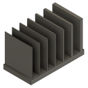
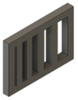
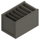
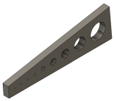
This study introduced a systematic framework to develop practical design guidelines specifically for filament-based material extrusion of metals (MEX/M), an additive manufacturing (AM) process defined by ISO/ASTM 52900. MEX/M provides a cost-efficient alternative to conventional manufacturing methods, which is particularly valuable for rapid prototyping. Although AM offers significant design flexibility, the MEX/M process imposes distinct geometric and process constraints requiring targeted optimization. The research formulates and validates design guidelines tailored for the MEX/M using an austenitic steel 316L (1.4404) alloy filament. The feedstock consists of a uniform blend of 316L stainless steel powder and polymeric binder embedded within a thermoplastic matrix, extruded and deposited layer by layer. Benchmark parts were fabricated to examine geometric feasibility, such as minimum printable wall thickness, feature inclination angles, borehole precision, overhang stability, and achievable resolution of horizontal and vertical gaps. After fabrication, the as-built (green-state) components undergo a two-step thermal post-processing treatment involving binder removal (debinding), followed by sintering at elevated temperatures to reach densification. Geometric accuracy was quantitatively assessed through a 3D scan by comparing the manufactured parts to their original CAD models, allowing the identification of deformation patterns and shrinkage rates. Finally, the practical utility of the developed guidelines was demonstrated by successfully manufacturing an impeller designed according to the established geometric constraints. These design guidelines apply specifically to the machine and filament type utilized in this study.
1. Introduction
Additive manufacturing (AM) technologies have revolutionized the manufacturing landscape by facilitating the direct fabrication of complex geometries from digital models through a layer-by-layer process. Unlike conventional techniques such as milling and casting, AM enables the creation of intricate structures which were previously unattainable with traditional subtractive or formative methods. This capability makes AM particularly advantageous for lightweight, biomimetic, and topology-optimized components that are relevant in the aerospace, biomedical, and automotive industries [1]. Additionally, AM allows the consolidation of multiple parts into single monolithic structures, significantly reducing material usage, assembly complexity, and overall production costs [2]. Among AM technologies, filament-based material extrusion of metals (MEX/M), also known as metal fused-filament fabrication (metal FFF) according to ISO/ASTM 52900 https://www.iso.org/obp/ui/#iso:std:iso-astm:52900:ed-2:v1:en, 3 May 2025, has attracted significant attention due to its distinctive advantages [2,3]. In MEX/M, a filament composed of metal powder and polymer binder is extruded through a heated nozzle and deposited layer-wise to form a “green” component. Subsequently, the part undergoes thermal processing to achieve final densification. Compared to selective laser melting (SLM), direct metal laser sintering (DMLS), and electron beam melting (EBM) AM methods, MEX/M generates less material waste and mitigates the safety risks associated with the handling of fine metal powders, providing a safer and more cost-effective alternative for metal part production [2].
Furthermore, MEX/M systems are typically compact, versatile, and cost-efficient, expanding their applicability to diverse industrial fields, including aerospace and biomedical sectors [3,4]. However, the process has some drawbacks, such as a low relative density, which does not meet the standards of the metal injection moulding process [2,3]. To meet this standard, the acquisition of an expensive process chain that requires, among other things, a powerful sintering furnace negates the cost-effectiveness compared to other AM processes. Further process-related drawbacks are the low production speed, which is slower due to the multi-stage process; higher surface roughness, which depends on the nozzle diameter [3]; and the limitation of the component size due to the sintering process. These disadvantages make it necessary to investigate process parameters and design aspects in order to identify suitable applications for the MEX/M process.
In this study, the focus is on the production of metal components using austenitic stainless steel 316L (1.4404) via MEX/M [2,3]. 316L stainless steel is chosen for its superior corrosion resistance, high tensile strength, excellent weldability, biocompatibility, and mechanical stability, making it suitable for biomedical implants, chemical processing equipment, and marine structures [5,6,7]. The capability of 316L stainless steel to fabricate complex geometries with high structural integrity is particularly beneficial for additive manufacturing [8]. Despite its advantages, the MEX/M process introduces several challenges, including minimum printable wall thickness, overhang stability, feature resolution, and significant dimensional shrinkage during the sintering phase [9,10]. Additionally, anisotropic properties resulting from layer-wise deposition affect the mechanical behaviour of final components, highlighting the need for optimized design guidelines [11,12,13]. Previous studies, such as that of Rebaioli [14], emphasize the necessity of developing comprehensive geometric benchmarks tailored specifically for different AM technologies and materials. Desktop metal has established design guidelines specific to its bound metal deposition (BMD) AM technology [15]. Consequently, the primary objective of this research is to establish a systematic set of design guidelines specific to MEX/M constraints and capabilities. These guidelines are developed with the following aims:
- Assist designers in optimizing part geometries for enhanced manufacturability in the MEX/M process.
- Evaluate the impact of process parameters on shrinkage behaviour, dimensional accuracy, and geometric fidelity.
- Validate the potential of MEX/M for producing high-density metal components.
- Increase technology acceptance and reduce experimental effort and material costs [16]
2. Materials and Methods
In the following section, selected geometric features representative of typical industrial components are described. These features have been effectively integrated into established additive manufacturing (AM) design guidelines [14,16,17,18]. The guidelines presented here are formulated based on the specific machine parameters and processing conditions used in a controlled environment.
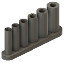
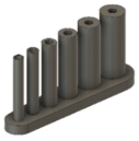
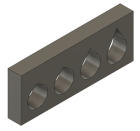
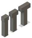
For this investigation, the 316L (1.4404) filament was supplied by PT + A (Dresden, Germany) [19]. The initial powder composition, along with the recommended debinding and sintering parameters, were specified in the datasheet provided by the PT + A, as summarized in Table 1 and illustrated in Figure 1. The filament diameter was 2.85 ± 0.05 mm, and the metal powder exhibited a size distribution between 2 µm and 15 µm. The feedstock was composed of 316L stainless steel powder particles uniformly mixed with a polymeric binder system. This mixture was embedded within a thermoplastic matrix. The chemical composition of the primary and secondary backbone binder is not disclosed by the filament supplier. Benchmark specimens were fabricated to evaluate geometric constraints, such as minimum printable wall thickness, feature inclination angles, borehole precision, overhang stability, and resolution of horizontal and vertical gaps. Table 2 summarizes the process parameters applied in this study to produce green parts. The specific geometric features and their dimensions evaluated in this study are listed in Table 3. The manufactured samples with the resulting geometric deviations can be observed in Table A1 in the Appendix A. The slicing and toolpath generation were performed using Simplify3D software Version 4.1.2 (Simplify3D, Cincinnati, OH, USA), and optimized printing parameters, derived from prior studies, were applied to achieve consistent extrusion and optimal interlayer adhesion. Benchmark specimens were printed using a Renkforce RF 2000 3D printer (Conrad Electronic SE, Hirschau, Germany), employing a direct-drive extruder with constant filament feeding.

Table 1.
Material composition for 316L (1.4404), reproduced from [19].
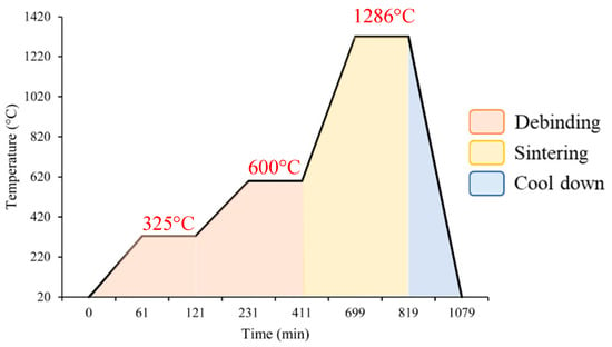
Figure 1.
Thermal cycle of the debinding and sintering process adapted from [17].

Table 2.
MEX process parameters [18].

Table 3.
Selected design features.
Chemical debinding of the green-state components was carried out using acetone as the solvent-based debinding agent. The debinding procedure was performed at a controlled temperature at 40 °C for 12 h, maintaining a sample-to-solvent volume ratio of 8:1 according to the filament manufacturer recommended guidelines. Post-debinding analysis indicated an average mass loss of around 5%, consistent with the supplier’s provided data. Following chemical debinding, specimens underwent thermal debinding and sintering processes in a high-temperature ExSO90 furnace (Aim3D GmbH, Rostock, Germany). These processes were integrated into a single continuous thermal cycle, with peak sintering temperatures reaching 1286 °C. This temperature was selected based on prior studies to achieve final part densities greater than 95% [17]. To prevent oxidation during thermal processing, a high-purity argon atmosphere (99.9% purity) with a steady gas flow of 1 L/min was maintained throughout the cycle. The thermal debinding consisted of two distinct isothermal stages: an initial stage at 325 °C for 1 h, followed by a second stage at 600 °C for 3 h. The heating rate was controlled at 300 K/h until the first holding temperature was achieved and was subsequently reduced to 150 K/h, optimizing binder removal while minimizing thermal stresses.
2.1. Density and Porosity Measurement
Measurements of the mass loss from chemical debinding and density were conducted based on Archimedes principle, utilizing a precision analytical balance (MJ-300 series, Chyo YMC Co., Ltd., Kyoto, Japan). Porosity was calculated using measurements of dry specimen mass in air () and the immersed mass in fluid (). The density of the component () was then derived from these values using Equation (1). Porosity () was calculated from the measured density according to Equation (2). Ethanol, with a known density, , was chosen as the immersion fluid due to its low surface tension and favourable wetting characteristics, reducing potential measurement inaccuracies from trapped air bubbles.
2.2. Dimensional Analysis and Shrinkage Qualification
Dimensional measurements were conducted along the X, Y, and Z axes using a digital Vernier calliper and a Keyence VK-X150 microscope (Osaka, Japan). Each specimen was measured at multiple points, including edges and central regions, to accurately capture variations caused by non-uniform shrinkage. Surface roughness was specifically evaluated on downskin areas of inclined walls, as these regions often experience material sagging and present significant challenges in maintaining dimensional stability during sintering. The Keyence digital microscope used in this study comprises a VHX-7020 digital camera, VH-Z20T lens, VHS-S600E holder, and VHX-970F control unit with an integrated display. Magnification adjustments between 20X and 200X facilitated detailed visual inspections, geometric measurements, and surface roughness evaluations.
2.3. Geometric Accuracy Assessment Using 3D Scanning
Conventional measurement tools were inadequate for accurately capturing the intricate details of the demonstrator impeller produced using the MEX/M process. To address this challenge, a Keyence VL-500 3D coordinate measurement system, offering a measurement accuracy of ±10 µm, was utilized for high-resolution scanning of the component’s geometry and surface texture. Scanning operations, data acquisition, and subsequent analysis were managed using Keyence VL-500 Application Series software Version 2.3.6.74 [20]. The scanning parameters specified in Table 4 were uniformly applied to all design features, in both green and sintered states. Due to variations in surface reflectivity at different stages of processing, scanner brightness settings were manually calibrated for each component to enhance data quality. Dimensional analysis of basic geometric features, such as circular elements, was carried out directly within the software using the “Cylinder” function located under the “3D Measurement—Basic Measuring Elements” tab. For measuring distances and angles between planar surfaces, reference planes were first established, after which the “Distance” or “Angle” functions under the “3D Measurement Between Two Planes” tab were employed. In addition to fundamental geometric measurements, the 3D scan data provided supplemental information for assessing shrinkage-induced deformations. This integrated method ensured accurate evaluation of both linear and volumetric shrinkage throughout the manufacturing process.

Table 4.
Keyence VL 500 settings.
Dimensional deviations were visualized by comparing the 3D scan data with proportionally scaled CAD (S-CAD) models using the VL-500 series software. Initially, the point clouds were manually aligned to the STL models using defined reference planes, followed by a precise alignment using the software’s built-in “fit” function. Subsequently, dimensional deviations were determined through the “3D compare” function, allowing quantification of tolerance differences between the scanned data and the original CAD geometries. To ensure accurate and meaningful comparisons, the CAD models were scaled according to experimentally derived shrinkage factors. This methodology facilitated reliable assessments of dimensional accuracy, clear identification of deformation patterns, and thorough validation of the shrinkage characteristics inherent to the MEX/M process.
3. Results and Discussion
3.1. Shrinkage Behaviour (WmS, BH, ZHs, and TD)
Shrinkage in the MEX/M process is primarily attributed to the sintering stage [17]. This study systematically investigates the shrinkage behaviour to establish reference values that can be utilized to compensate for dimensional changes during these stages. By incorporating these reference values, components can be initially designed to meet target dimensions and subsequently scaled in slicing software to account for the predicted shrinkage. To evaluate shrinkage behaviour, the external dimensions of the components were measured in three distinct process states: green (as-built), debinded, and sintered. By comparing these measurements, dimensional changes that occurred throughout each stage of the manufacturing process were quantified.
The results of this analysis are presented in Figure 2 and Table 5. Substantial dimensional shrinkage primarily occurs during the sintering stage. During the chemical debinding phase, parts exhibited an average shrinkage of 1.8% ± 0.2% along the X and Y axes, while shrinkage along the Z axis was lower, measured at 0.8% ± 0.3%. After transitioning from the green state to the sintered state, shrinkage intensified, with reduction factors of 0.845 ± 0.004 in the X and Y directions and 0.851 ± 0.002 in the Z direction.
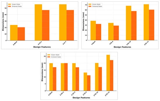
Figure 2.
Comparison of shrinkage of design features in X, Y and Z directions (the first letter denotes the axis; WmS: supported walls; LK,a: boreholes manufactured in a vertical direction (BH-V); LK,f: boreholes manufactured flat on the building platform (BH-H);TD: teardrop borehole; ZH: hollow cylinder. The last number denotes the diameter of the feature cavity).

Table 5.
Shrinkage behaviour in X, Y and Y axis of design features.
This increase in shrinkage was accompanied by greater dimensional variability, as reflected in the higher standard deviations observed post-sintering. Unlike trends reported in previous studies [21,22], shrinkage along the Z axis was lower than in the X and Y directions. This deviation is likely due to the relatively small dimensions and fine features of the fabricated geometries, which contributed to a more isotropic shrinkage behaviour. The experimentally determined shrinkage factors were used to scale the CAD models for dimensional comparisons against the sintered components (S-CAD models). To account for the shrinkage observed during slicing, the recommended scaling factors are 1.183 for the X and Y axes and 1.176 for the Z axis. These adjustments are essential to ensure dimensional accuracy in the final sintered parts.
3.2. Dimensional Deviations of Design Features
3.2.1. Unsupported and Supported Wall Features (WoS and WmS):
Wall thicknesses exceeding 0.6 mm were successfully fabricated without the use of sidewall support, as shown in Figure 3a in the green (as-built) state. The specimen with a nominal wall thickness of 0.6 mm exhibited undersizing of up to 0.23 mm at its upper right corner. Furthermore, the presence of a visible staircase effect in Figure 3 highlights inconsistencies in filament extrusion, indicating non-uniform material deposition during the MEX/M process.
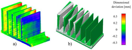
Figure 3.
Three-dimensional scan results of unsupported wall (WoS) specimens, (a) green state, (b) debinding state.
After chemical debinding, pronounced dimensional deviations were observed in samples lacking sidewalls, with deformation becoming more severe during the debinding stage, as illustrated in Figure 4. The STL model, scaled to account for shrinkage, is shown in green, while the corresponding 3D scan data are presented in grey in Figure 3b. In general, wall thicknesses of 1.6 mm or more could be reliably fabricated [23]. The defects observed during debinding are attributed to anisotropic diffusion mechanisms, which lead to uneven binder removal and subsequent wall deformation [10].
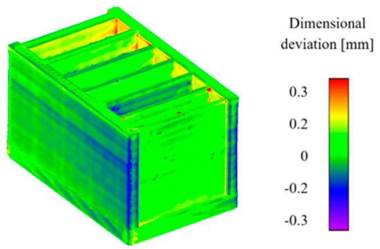
Figure 4.
Three-dimensional scan results of supported wall (WmS) specimens in green state.
Incorporating sidewalls allows for the successful fabrication of walls as thin as 0.2 mm. A comparison between the CAD model and 3D scan data (Figure 4) indicates only minor dimensional deviations, aside from the naturally rounded edges attributed to the nozzle diameter. However, despite applying the shrinkage compensation factor to the STL model, deviations following the debinding process were particularly persistent in the side and rear walls, which display outward expansion. G-code analysis revealed that these 2 mm thick walls lacked internal infill, resulting in structural voids. This absence of internal support is likely responsible for the observed deformations, even in regions where internal connections were present.
After the debinding process, increased dimensional deviations were observed in several regions, even though the STL file had been adjusted to compensate for expected shrinkage. Outward deformation was especially evident in the sidewalls and rear wall, with the effect being most pronounced in walls with a nominal thickness of 2 mm. A detailed examination of the slicer-generated G-code revealed that these walls were printed without any internal infill, leading to the formation of structural voids. The absence of internal support likely contributed to the observed deformations, despite the walls being partially connected at their midsections. Furthermore, some deviations can be attributed to limitations in the accuracy of the shrinkage prediction model used during pre-processing. A comparison of deformation patterns before and after sintering, shown in Figure 5 and Figure 6, indicates that while the overall geometry remained largely consistent, minor reductions in distortion were noted, particularly in the right-side and rear wall regions.
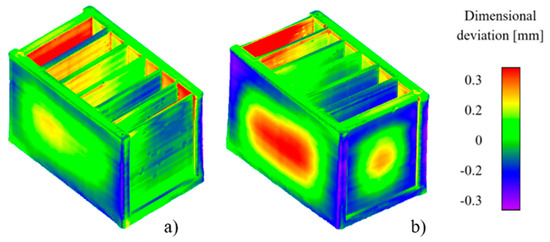
Figure 5.
Three-dimensional scan of support wall specimens (WmS) in debinded state. (a) Front view. (b) Rear view.
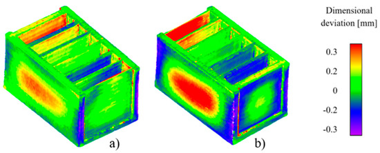
Figure 6.
Three-dimensional scan of sintered support wall specimens (WmS) in debinded state. (a) Front view. (b) Rear view.
The measured wall thicknesses of the samples are presented in Figure 7. Although walls with a nominal thickness below 0.2 mm were successfully fabricated, they exhibited actual thicknesses of approximately 0.4 mm, due to the nozzle size used. In the MEX/M process, the actual dimensions of walls closely matched the nominal values of 0.4 mm and 0.6 mm, which was attributable to the single-track fabrication method employed for both wall types. This fabrication approach results in a relatively high standard deviation of 0.10 mm around a mean dimensional deviation of 0.09 mm for sintered MEX/M components.
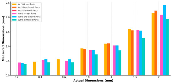
Figure 7.
Dimensional deviation of the supported (WmS) and unsupported walls (WoS) samples in Green, debinded, and sintered states.
3.2.2. Cylinders and Hollow Cylinders with Different Thicknesses (ZV And ZH-2, ZH-4):
Cylindrical structures with nominal diameters of 0.2 mm and 0.4 mm could not be fabricated, as these fine features were excluded during the slicing stage. As shown in Figure 8a, cylinders with smaller diameters in the green state displayed notably higher dimensional deviations than those with larger cross-sections, suggesting a direct relationship between reduced cross-sectional area and increased geometric instability.
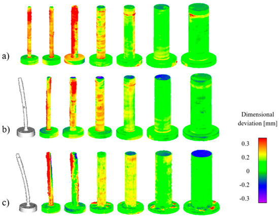
Figure 8.
Three-dimensional scan results of cylindrical specimens [ZV]. (a) Green state; (b) debinded; (c) sintered.
The cylinder with a nominal diameter of 0.8 mm exhibited dimensional deviations of up to 0.42 mm, whereas the largest deviations reaching approximately 0.5 mm were observed in cylinders with diameters of 1 mm and 2 mm. Across all samples, the interface between the cylinder and its base was consistently rounded, leading to localized oversizing. The layer-specific dimensional variations were likely due to extrusion inconsistencies, indicating non-uniform material deposition during the printing process. After the chemical debinding stage, the smallest cylinder showed noticeable deformation (Figure 8b).
In contrast, geometric distortions in the other cylinders remained largely unchanged, suggesting that these deformations originated during the MEX/M fabrication phase and persisted thereafter. During the subsequent sintering process (Figure 8c), further bending occurred in the 1 mm and 2 mm cylinders. The degree of curvature was found to be inversely proportional to the cylinder diameter, with smaller cylinders exhibiting greater bending. The cylinder with the largest diameter displayed undersizing of up to 0.19 mm on its top surface.
In other cases, the undersizing evident in the brown parts was partially reduced after sintering, indicating that some dimensional recovery occurred during densification. Additionally, deviations observed at the base of the sintered cylinders were attributed to optical artefacts, likely caused by surface reflectivity interfering with the accuracy of the 3D scan system. A clear correlation between component diameter and dimensional oversizing is observed in the green-state samples shown in Figure 8, justifying a closer examination of this relationship. This trend remains consistent across both the green-state specimens in Figure 8a and the sintered counterparts in Figure 8c.
Hollow cylinders (ZHs) were produced with two nominal wall thicknesses, 2 mm and 4 mm, and included both uniform and varying wall thickness configurations, as shown in Figure 9a,b. In the green state, the outer hollow cylinders exhibited a slight inward deflection toward the central axis, with this deformation being more pronounced in the larger-diameter specimens. During the debinding stage, this deflection became more severe, as illustrated in Figure 9c,d, indicating a loss of structural stability.
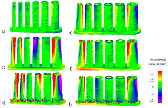
Figure 9.
Three-dimensional scan results. Hollow cylinder specimens. (a,c,e) ZH-2 mm samples in green, debinded and sintered states, and (b,d,f) ZH-4 mm samples in green, debinded, and sintered states.
In the smaller samples, the central cylinder also showed significant tilting, which contributed to noticeable dimensional deviations, particularly in the upper regions. These deformation patterns were consistently observed in both ZH-2 and ZH-4 samples, especially in areas with a wall thickness of 0.2 mm. After sintering, as depicted in Figure 9e,f, the degree of tilt in the smaller cylinders increased markedly, while the dimensional deviations in the larger samples remained relatively unchanged. Form deviations at the base of the samples were also observed; however, these were primarily attributed to optical artefacts from surface reflectivity, rather than actual geometric distortions. The outer diameters of both solid and hollow cylinder specimens are summarized in Table 6.

Table 6.
Inner diameter of the hollow cylinders.
Due to structural damage incurred by the hollow cylinders during debinding, it was not possible to derive reliable shrinkage data between the green and debinded states. After accounting for shrinkage, the average dimensional deviation of the outer diameters was 0.09 mm, with a relatively high standard deviation of 0.14 mm. This variation is attributed to the accumulation of dimensional errors originating during green part fabrication, compounded by the inherent uncertainties in shrinkage behaviour during sintering. The green-state specimens alone showed an average dimensional deviation of 0.12 mm with a standard deviation of 0.17 mm, highlighting the overall process variability associated with the MEX/M technique. External dimensions of cylinder and hollow cylinder samples were summarized in Figure 10.
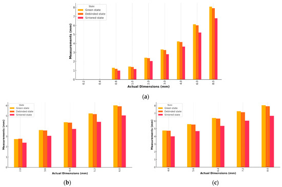
Figure 10.
External dimensions for the samples in green, debinded, and sintered states (a) ZV, (b) ZH-2 and (c) ZH-4 samples.
To quantitatively assess this correlation, the dimensional deviations were plotted against the nominal diameters of the solid cylindrical samples, as illustrated in Figure 11. The observed linear relationship in the MEX/M-fabricated cylinders was further confirmed through a regression analysis, resulting in the following equation:
where dabw represents the dimensional deviation and d denotes the cylinder diameter. The coefficient of determination R2 of 0.874 confirms a strong linear relationship between these variables.
dabw = −0.0461 × d + 0.3827
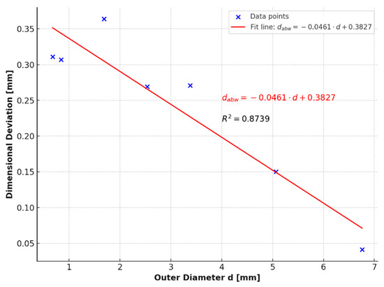
Figure 11.
Dimensional deviation of the outer diameter of ZV samples.
The dimensional behaviour of the hollow cylinders, as shown in Figure 12, follows a trend consistent with the patterns observed in the ZV specimens. A linear regression model was used to describe the relationship between the outer diameter and the dimensional deviation for the ZH-2 and ZH-4 samples, and is given as follows:
dabw = −0.0211 × d + 0.0724
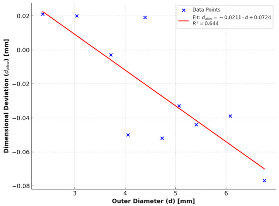
Figure 12.
Dimensional deviation of the outer diameter of ZH-2 mm and ZH-4 mm samples.
The coefficient of determination (R2 = 0.644) indicates a moderate correlation between the predicted and measured values, with a noticeable degree of data scatter. This variation, coupled with the lower R2 value, is likely due to inconsistencies in cylinder wall thickness, which contribute to the observed dimensional deviations.
Cylinders with the smallest wall thickness exhibited pronounced dimensional deviations in the green part stage. This behaviour is primarily attributed to the mismatch between the nozzle diameter and the intended wall thickness. Specifically, the nozzle diameter exceeded the wall thickness, resulting in compromised dimensional accuracy.
As shown in Table 6, the internal diameters of the hollow cylinders demonstrate this deviation clearly. Due to the extent of the discrepancies, samples with a 0.2 mm wall thickness were excluded from the dimensional analysis to preserve the accuracy and integrity of the data. For the remaining ZH-2 and ZH-4 samples, the average dimensional deviation in internal diameter was measured at −0.24 mm, with a standard deviation of ±0.04 mm, indicating a consistent undersizing trend relative to the nominal design values.
3.2.3. Horizontal Overhangs (HOs):
Noticeable dimensional deviations were observed in single-sided supported overhangs starting from lengths as short as 1 mm. As shown in Figure 13, overhangs exceeding this threshold displayed pronounced layer sagging, resulting in significant geometric inaccuracies. To minimize such deviations, it is advisable to incline single-sided overhangs from the 1 mm mark onward during the green part stage or to implement support structures to improve stability. Additionally, rounding at the edges of the green parts was evident, and was primarily caused by the nozzle diameter, which in turn contributed to undersized features in the final components.
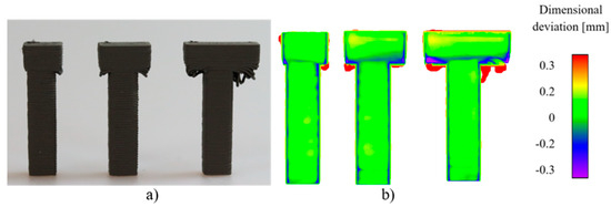
Figure 13.
(a) Green (as-built) and (b) 3D scan results of HO samples.
The debinding and sintering processes were completed without major complications. Overhangs that were free of visible defects in the green state retained their shape well throughout post-processing, as illustrated by the comparison between Figure 13b and Figure 14a. Microscopic analysis of the 0.5 mm and 1 mm overhangs (Figure 14a) showed that the 1 mm sample retained distinct sagging layers indicative of deformation originating during the initial printing phase.
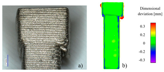
Figure 14.
Sintered horizontal overhang (HO) sample. (a) Microscope image. (b) Three-dimensional scan results.
In the green-state specimens featuring double-sided supported overhangs, deformations became evident once the overhang length exceeded 2 mm, as illustrated in Figure 15.
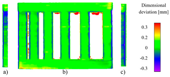
Figure 15.
Three-dimensional scan results of green part of the horizontal overhang (HO) sample. (a) Right view. (b) Front view. (c) Side view.
After undergoing the chemical debinding process, the defects characteristic of the MEX/M process remained and were further exacerbated by additional warping at the component corners. As shown in Figure 16a, two diagonally opposite corners lifted upwards, while the other two experienced downward displacement.
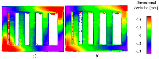
Figure 16.
Three-dimensional scan results of horizontal overhangs (HOs) sample. (a) Debinded state. (b) Sintered state.
These distortions led to dimensional deviations, with elevated corners showing oversizing of up to 0.69 mm, while the depressed corners exhibited undersizing of up to 0.56 mm. Although the sintering process helped reduce some of these deformations, they remained noticeable, with oversizing at the raised corners measuring 0.40 mm and undersizing at the lowered corners reaching 0.37 mm.
3.2.4. Boreholes and Teardrop Shapes (BH and TD)
Circular boreholes (BHs) and teardrop-shaped (TD) features were successfully produced in both vertical and horizontal orientations. However, specimens printed in the vertical orientation exhibited greater dimensional deviations compared to their horizontally printed counterparts.
The green-state vertical borehole (BH-V) specimens with diameters of 8 mm, 6 mm, and 4 mm showed visible layer sagging, leading to significant oversizing, as seen in Figure 17a. In contrast, the horizontally printed samples exhibited a slight curvature, characterized by raised edges and a depressed central region. After the debinding step, defects originating from the green-state fabrication remained evident, and further deformations developed in both orientations. As shown in Figure 17c,d, a convex distortion pattern was observed, marked by lower ends and an elevated centre in the borehole geometry.
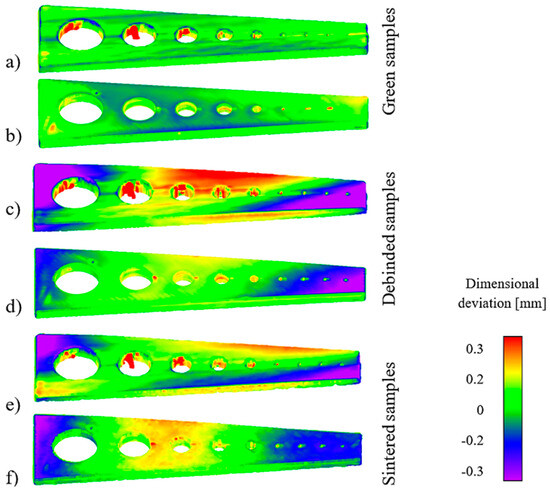
Figure 17.
Three-dimensional scan results of the boreholes samples with vertical and horizontal build direction. (a) Green BH-V. (b) Green BH-H. (c) Debinded BH-V. (d) Debinded (BH-H). (e) Sintered BH-V. (f) Sintered BH-H.
In the vertically printed specimens (Figure 17c), the maximum oversize at the centre reached 0.35 mm, while undersizing was observed at 0.70 mm on the left side and 0.57 mm on the right. In comparison, the horizontally built borehole (BH) samples showed less deformation, with a central oversize of 0.17 mm. Following the sintering process, the convex deformation observed in the vertical specimens was partially reduced; the central oversize decreased to 0.24 mm, and the undersizing on both sides was reduced to approximately 0.40 mm. Conversely, in the horizontal BH specimen, the central oversize increased slightly to 0.22 mm after sintering. Figure 18 and Figure 19 show the measured dimensions of BH samples fabricated in both horizontal and vertical orientations. Across all cases, the measured diameters were smaller than the nominal values. The average dimensional deviation was −0.37 mm, with a standard deviation of ±0.11 mm, which is notably greater than the deviations observed in the internal diameters of the hollow cylinders.
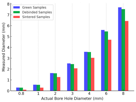
Figure 18.
Dimensional deviation of the BH-H samples in green, debinded, and sintered states.
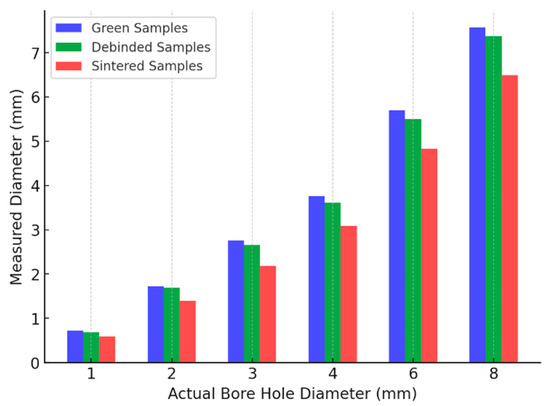
Figure 19.
Dimensional deviation of the BH-V samples in green, debinded, and sintered states.
To minimize defects when fabricating larger boreholes aligned parallel with the x–y plane, an effective strategy is to incorporate an angular inclination in the upper regions of the holes [9]. This approach was applied in the TD specimens, which featured teardrop-shaped holes with diameters of 6 mm and 14 mm. A consistent shrinkage pattern was observed across all green-state parts, as shown in Figure 20. Notably, the outer edges of the holes exhibited oversizing along the surfaces facing the nearest component boundary, while no undersizing was detected on the opposite side. Additionally, Figure 20b reveals a horizontal stripe near the upper edge of the component, which was not observed during visual inspection and is therefore considered a measurement artefact.
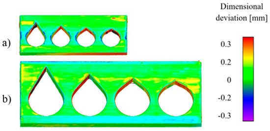
Figure 20.
Three-dimensional scan result of TD samples in green state: (a) 6 mm and (b) 14 mm.
After the debinding process, further deformations were observed. In the specimen with a 6 mm diameter (Figure 21a), localized oversizing of up to 0.26 mm was measured at the corners. The 14 mm diameter specimen (Figure 21b) showed both oversizing—up to 0.19 mm—and undersizing, reaching up to 0.35 mm. These deformations became more pronounced following the sintering stage. As illustrated in Figure 22a,b, both undersizing and oversizing were evident across all of the examined specimens.
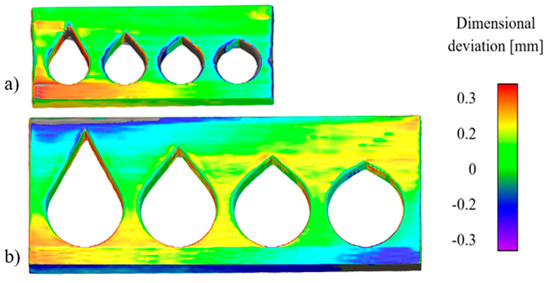
Figure 21.
Three-dimensional scan result of TD samples in debinded state: (a) 6 mm (b) 14 mm.
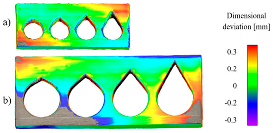
Figure 22.
Three-dimensional scan result of TD samples in sintered state: (a) 6 mm (b) 14 mm.
3.2.5. Inclined Walls (DWs):
Inclined wall features were designed with a range of angles from 0° to 90°, in 10° increments. The dimensional deviations observed in both the green and sintered states are shown in Figure 23. In the green parts, oversizing was evident in several regions, while undersizing was primarily found along the rounded edges of the components. Surfaces with shallower angles exhibited a pronounced stair-stepping effect, which was attributed to the layer-by-layer deposition characteristic of the MEX/M process. As shown in Table 7, downskin angles of 30° and above were successfully manufactured. However, a downskin angle of 10° could not be printed due to significant layer sagging. Dimensional deviations increased noticeably during the debinding stage, particularly for samples with lower inclination angles. Green-state specimens with shallow downskin angles exhibited the highest deviations, which further intensified after sintering. On average, the measured downskin angles deviated by approximately +4° from the nominal design values, with a standard deviation of ±1°.
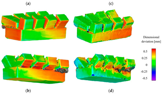
Figure 23.
Three-dimensional scan results of the DW samples. (a,b) Green state. (c,d) Sintered state.

Table 7.
Measured angle of the DW samples comparison.
3.3. Guidelines for Design and Production
The design guidelines derived from the analysis of the fabricated 316L samples using the MEX/M process are summarized in Table 8. The specified dimensions refer to the sintered components, under the assumption that the initial CAD models are scaled accordingly in the slicing software to account for process-induced shrinkage. In addition to nominal values, the expected dimensional deviations are provided in the Supplementary Data [22]. It is clear that these deviations are geometry-dependent, varying with the shape and structural complexity of each component. Moreover, due to deformation effects introduced during the debinding and sintering stages, the production of flat geometries is not recommended, as ensuring dimensional stability in such cases remains particularly difficult.

Table 8.
Design guidelines of features printed via the MEX/M process using AISI 316L.
3.4. Demonstrator:
To demonstrate the industrial applicability of the MEX/M additive manufacturing process, an impeller structure adapted and redesigned from the model in [24] was fabricated based on the design guidelines established in Chapter 3. The component incorporates several critical features, including angled walls exceeding 30°, boreholes with a diameter of 7 mm, and a minimum wall thickness of 2 mm.
The demonstrator impeller was successfully fabricated using the MEX/M process with 316L filament. As shown in Figure 24a, the green (as-built) sample is positioned on the right, while the sintered part is on the left. The measured shrinkage of the impeller was approximately 13.97% in the X-Y plane and 14.69% along the Z-axis (build direction), which falls within the acceptable limits reported for the MEX/M process [9,10,11,12,13,25].
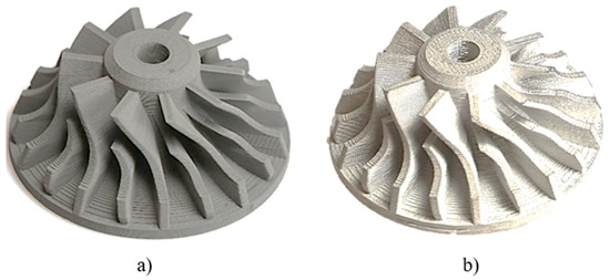
Figure 24.
A 316L impeller fabricated using the MEX/M process. (a) The green part is on the left; (b) the sintered part is on the right.
However, dimensional deviations of up to ±0.2 mm were observed when comparing the sintered impeller with the original CAD model and 3D scan data, analyzed using the VMX500 software (version 2.3.6.74) from KEYENCE GmbH. These deviations are illustrated in Figure 25: (a) shows the 3D scan of the green-state impeller, and (b) compares the sintered component to the scaled CAD model. For accurate comparison, the CAD model was scaled by a factor of 0.853 in the X and Y directions and 0.881 in the Z direction, as determined by the experimentally measured shrinkage rates.
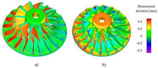
Figure 25.
Dimensional deformation of 3D scan impeller. (a) Green state; (b) sintered state.
Minor discrepancies in the scan data may arise due to the high reflectivity of the metal surface during scanning. Such deviations can be compensated by incorporating appropriate dimensional tolerances in the design phase to ensure proper fit and functionality after the sintering process. The material extrusion of metals (MEX/M) additive manufacturing process demonstrates strong potential for industrial-scale applications, particularly when guided by the design recommendations developed in this study. By applying these principles, MEX/M emerges as a competitive alternative to conventional metal manufacturing methods, enabling advancements in lightweight design, customized component production, and multi-material fabrication.
A comparison with existing design guidelines for the MEX/M process shows differences in the limits on design features when using the same nozzle diameter [15]. For example, horizontal holes with a diameter of 0.68 mm and a maximum deviation of 0.44 mm can already be produced with the design features examined. According to reference [15], a minimum hole size of 1.5 mm is recommended. The existing design recommendations from [15] are material-independent, so they allow for greater tolerance and deviate from the design elements examined in this study.
In conclusion, it can be deduced from the dimensional shrinkage in the various design features that these designs depend on the process parameters of shaping, debinding, and sintering. During the shaping process, the extrusion multiplier, the layer height and the layer thickness which, in turn, depend on the extrusion temperature, influence the bonding of the individual extrusion layers. A leaky bond leads to internal voids, which can cause shrinkage in the Z direction during solidification, as was observed with the different design features. In the debinding process, the debinding temperature, and the temperature gradient have the greatest influence on the final shrinkage. If the debinding temperature is excessively high, the temperature gradient becomes extremely large, leading to anisotropic deformation of the components, causing undesirable deformation in the subsequent sintering process. This observation could be made in the unsupported walls. The heating rate, maximum temperature, and holding times have the greatest influence on dimensional shrinkage in the sintering process. Undesirable deformation of the design features can only be prevented by selecting these process parameters appropriately.
4. Conclusions and Outlook
In this paper, AISI 316L with different design features was manufactured and was evaluated after each process step (shaping, debinding, and sintering). It was shown that defects that occurred in the initial process steps had a negative impact on the later process steps and could not be rectified. With unsupported walls of 1.5 mm thickness, deviations of a maximum of 0.4 mm occurred, corresponding to the nozzle diameter. It could therefore be identified that the nozzle diameter has a significant influence on the accuracy of the different design features. Unsupported walls could already be successfully manufactured with a thickness of 0.2 mm. Cylinders can be produced from a diameter of 0.8 mm, whereby the geometric deviation here may also be 0.42 mm. The hollow cylinders with 2 mm and 4 mm hole diameters can be produced with a wall thickness of 1.6 mm. The maximum deviation here is 0.3 mm. Horizontal overhangs (supported on one and two sides) can be manufactured up to a length of 0.5 mm. Support structures must also be used. Bored holes that are produced lying on the building platform require a minimum diameter of 0.68 mm. Upright holes can have a maximum diameter of 2.53 mm. Larger drill holes must be supported or have a teardrop shape, which can have an angle of 60° to 120°. Overhang angles from 30° can be finished, but deviations of up to 0.45 mm occur in the downskin area.
The design limits were successfully applied to a component so that the deviation after sintering is approximately 0.26 mm. It should be noted that the design guidelines and recommendations for MEX/M were implemented based on 316L tested features with a 0.4 mm nozzle size. The recommended guidelines are specific to the machine setup, process parameters, and filament material specifications with respect to the identified design limits. The use of finer nozzles with a diameter of 0.2 mm can lead to features with smaller deviations, though they may impose additional manufacturing restrictions. However, the printing time in the shaping process is then increased.
As the design guidelines are dependent on material, process parameters, and equipment, these recommendations only apply to the configuration in this paper. If the material, equipment, or process parameters are changed, different specimens may be produced, and different design recommendations may result. Therefore, the methodological approach presented in this paper is generally transferable to other materials and equipment types. Furthermore, the results presented here provide an indication of deviations in design limits.
Author Contributions
Conceptualization, K.A.; methodology, K.A.; software, M.P.R.M.; validation, K.A. and T.R. (Tim Röver); formal analysis, K.A. and C.E.; investigation, T.R. (Titus Rakow); resources, K.A.; data curation, K.A.; writing—original draft preparation, K.A. and M.P.R.M.; writing—review and editing, K.A.; visualization, K.A., T.R. (Titus Rakow) and M.P.R.M.; supervision, K.A. and C.E.; project administration, K.A and C.E.; funding acquisition, K.A. and C.E. All authors have read and agreed to the published version of the manuscript.
Funding
This research received no external funding.
Data Availability Statement
The original data presented in the study are openly available in [22].
Conflicts of Interest
The authors declare no conflict of interest.
Appendix A

Table A1.
Optical images of as-built ‘green’ components.
Table A1.
Optical images of as-built ‘green’ components.
Unsupported walls (WoSs)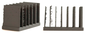 Thickness (mm): 0.2/0.4/0.6/0.8/1/1.5/2 Length (mm): 38.5 Width (mm): 20 Height (mm): 23 | Supported horizontal overhangs (ÜZs)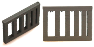 Overhang gap (mm):1/2/3/4/5 Height (mm): 23 Width (mm):3 |
Supported walls (WmSs)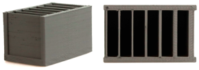 Thickness (mm): 2/1.5/1/0.8/0.6/0.4/0.2 Length (mm): 38.5 Width (mm): 20 Height (mm): 23 | Horizontal and vertical boreholes (BH-V, BH-H) 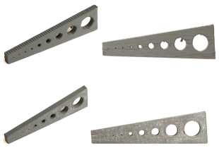 Bore diameter (mm): 0.4/0.6/0.8/1/2/3/4/6/8 |
Vertical cylinder (ZV) Bar Ø (mm): 8/6/4/3/2/1/0.8/0.4/0.2 Height (mm): 20 | Hollow cylinders (ZH-4)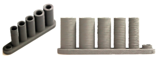 Thickness (mm): 0.4/0.8/1.6/2.4/3.2/4 Height (mm): 23 |
Hollow cylinders (ZH-2, ZH-4)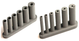 Thickness (mm): 0.4/0.8/1.6/2.4/3.2/4 Height (mm): 23 | Teardrops features (TDs)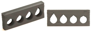 Angle (degree): 60/80/100/120 Diameter (mm): 6 |
Horizontal overhangs (HOs)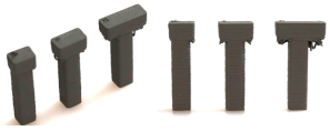 Overhang distance (mm): 0.5/1/1.5/2/3/4 | Inclined walls (DWs)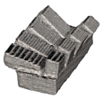 Incline angle (degree): 10/20/30/40/50/60/70/80 |
References
- Lopez, E.; Brueckner, F.; Gruber, S. 21—Industrial applications. In Fundamentals of Laser Powder Bed Fusion of Metals Additive Manufacturing Materials and Technologies; Yadroitsev, I., Yadroitsava, I., Plessis, A.D., MacDonald, E., Eds.; Elsevier: Amsterdam, The Netherlands, 2021; pp. 583–595. [Google Scholar]
- Sadaf, M.; Bragaglia, M.; Nanni, F. A simple route for additive manufacturing of 316L stainless steel via Fused Filament Fabrication. J. Manuf. Process. 2021, 67, 141–150. [Google Scholar] [CrossRef]
- Suwanpreecha, C.; Manonukul, A. A Review on Material Extrusion Additive Manufacturing of Metal and How It Compares with Metal Injection Moulding. Metals 2022, 12, 429. [Google Scholar] [CrossRef]
- Schatt, W.; Wieters, K.-P.; Kieback, B. Pulvermetallurgie: Technologien und Werkstoffe, 2nd ed.; bearbeitete und erweiterte Auflage; Springer: Berlin/Heidelberg, Germany, 2007. [Google Scholar]
- Zhong, Y.; Rännar, L.-E.; Liu, L.; Koptyug, A.; Wikman, S.; Olsen, J.; Cui, D.; Shen, Z. Additive manufacturing of 316L stainless steel by electron beam melting for nuclear fusion applications. J. Nucl. Mater. 2017, 486, 234–245. [Google Scholar] [CrossRef]
- García-Rodríguez, S.; Torres, B.; Pulido-González, N.; Otero, E.; Rams, J. Corrosion behavior of 316L stainless steel coatings on ZE41 magnesium alloy in chloride environments. Surf. Coat. Technol. 2019, 378, 124994. [Google Scholar] [CrossRef]
- Gong, H.; Crater, C.; Ordonez, A.; Ward, C.; Waller, M.; Ginn, C. Material Properties and Shrinkage of 3D Printing Parts using Ultrafuse Stainless Steel 316LX Filament. MATEC Web Conf. 2018, 249, 1001. [Google Scholar] [CrossRef]
- Röttger, A.; Boes, J.; Theisen, W.; Thiele, M.; Esen, C.; Edelmann, A.; Hellmann, R. Microstructure and mechanical properties of 316L austenitic stainless steel processed by different SLM devices. Int. J. Adv. Manuf. Technol. 2020, 108, 769–783. [Google Scholar] [CrossRef]
- Martignoni, L.; Vegro, A.; Candidori, S.; Shaikh, M.Q.; Atre, S.V.; Graziosi, S.; Casati, R. Prototyping and characterisation of 316L stainless steel parts and lattice structures printed via metal fused filament fabrication. Rapid Prototyp. J. 2024, 30, 123–141. [Google Scholar] [CrossRef]
- You, S.; Jiang, D.; Wang, F.; Ning, F. Anisotropic sintering shrinkage behavior of stainless steel fabricated by extrusion-based metal additive manufacturing. J. Manuf. Process. 2023, 101, 1508–1520. [Google Scholar] [CrossRef]
- Obadimu, S.O.; Kourousis, K.I. Shrinkage behaviour of material extrusion steel 316L: Influence of primary 3D printing parameters. Rapid Prototyp. J. 2022, 28, 92–101. [Google Scholar] [CrossRef]
- Cerlincă, D.-A.; Tamașag, I.; Beșliu-Băncescu, I.; Severin, T.-L.; Dulucheanu, C. Experimental investigation of FDM manufacturing of 316 l stainless steel. Int. J. Adv. Manuf. Technol. 2024, 135, 1449–1463. [Google Scholar] [CrossRef]
- Alzyod, H.; Ficzere, P. Optimizing fused filament fabrication process parameters for quality enhancement of PA12 parts using numerical modeling and taguchi method. Heliyon 2023, 9, e14445. [Google Scholar] [CrossRef] [PubMed]
- Rebaioli, L.; Fassi, I. A review on benchmark artifacts for evaluating the geometrical performance of additive manufacturing processes. Int. J. Adv. Manuf. Technol. 2017, 93, 2571–2598. [Google Scholar] [CrossRef]
- Desktop Metal. BMD-Design-Guide: Considerations and Best Practices; Desktop Metal: Burlington, MA, USA, 2023. [Google Scholar]
- Blunk, H.; Seibel, A. Design guidelines for metal binder jetting. Prog. Addit. Manuf. 2024, 9, 725–732. [Google Scholar] [CrossRef]
- Asami, K.; Lozares, J.M.C.; Ullah, A.; Bossen, B.; Clague, L.; Emmelmann, C. Material extrusion of metals: Enabling multi-material alloys in additive manufacturing. Mater. Today Commun. 2024, 38, 107889. [Google Scholar] [CrossRef]
- Asami, M.K.; Herzog, D.; Bossen, B.; Geyer, L.; Klemp, C.; Emmelmann, C. (Eds.) Design Guidelines for Green Parts Manufactured with Stainless Steel. In The Filament Based Material Extrusion Process for Metals (MEX/M); European Powder Metallurgy Association (EPMA): Chantilly, France, 2022. [Google Scholar] [CrossRef]
- PT&A, DS-Fil-316L-F-200222-11. Available online: http://www.pt-a.de/filament%20de.htm (accessed on 10 April 2025).
- Keyence, 3D Scanner—Modellreihe VL|KEYENCE Deutschland. 2025. Available online: https://www.keyence.de/landing/lpc/3d-scanner-modellreihe-vl.jsp?aw=KD_gaBRvlph1437971635824&gad_source=1&gclid=CjwKCAiA74G9BhAEEiwA8kNfpYLN2XsFjCROJXLdUsFD4vQa4FZXNOhQXbI7FvEsnTdpS2k2LvUMvxoChZgQAvD_BwE (accessed on 9 April 2025).
- Jiang, D.; Ning, F. Additive Manufacturing of 316L Stainless Steel by a Printing-Debinding-Sintering Method: Effects of Microstructure on Fatigue Property. J. Manuf. Sci. Eng. 2021, 143, 091007. [Google Scholar] [CrossRef]
- Asami, M.K.; Medapati, M.P.R.; Rakow, T.; Röver, T.; Emmelmann, C. Supplementary Data: Design Guidelines for Material Extrusion of Metals (MEX/M); TUHH Universitätsbibliothek: Hamburg, Germany, 2025. [Google Scholar]
- Asami, K.; Bartsch, K.; Emmelmann, C. Design-Richtlinie für die ressourceneffiziente Gestaltung von Stützstrukturanbindungen im pulverbettbasierten Laserstrahlschmelzen von Ti6Al4V. In Proceedings of the 17th Rapid. Tech 3D Conference, Erfurt, Germany, 22–23 June 2021; Carl Hanser Verlag GmbH & Co. KG: Munich, Germany, 2021. [Google Scholar]
- Thingiverse.com, Impeller by Team3187FRC. 2025. Available online: https://www.thingiverse.com/thing:2426666 (accessed on 9 April 2025).
- Ait-Mansour, I.; Kretzschmar, N.; Chekurov, S.; Salmi, M.; Rech, J. Design-dependent shrinkage compensation modeling and mechanical property targeting of metal FFF. Prog. Addit. Manuf. 2020, 5, 51–57. [Google Scholar] [CrossRef]
Disclaimer/Publisher’s Note: The statements, opinions and data contained in all publications are solely those of the individual author(s) and contributor(s) and not of MDPI and/or the editor(s). MDPI and/or the editor(s) disclaim responsibility for any injury to people or property resulting from any ideas, methods, instructions or products referred to in the content. |
© 2025 by the authors. Licensee MDPI, Basel, Switzerland. This article is an open access article distributed under the terms and conditions of the Creative Commons Attribution (CC BY) license (https://creativecommons.org/licenses/by/4.0/).
