1. Introduction
The advent of mixed reality (MR) technology has revolutionized how we interact with digital information, blending virtual elements with the physical world. Unlike virtual reality, which immerses users in a completely digital environment, MR merges realistically and seamlessly virtual objects within the real world, enhancing users’ sensory experience with a high level of local presence [
1,
2]. This integration has led to significant advancements across various sectors. For instance, in education, MR facilitates immersive learning experiences [
3,
4,
5], allowing people to visualize complex concepts through interactive 3D models. In healthcare, MR assists surgeons by overlaying critical data during procedures, thereby improving precision and outcomes [
6], and motivates users to perform rehabilitation exercises [
7]. Also, the entertainment engineering industry has embraced MR to create engaging experiences, such as interactive gaming environments that merge virtual characters with real-world settings [
8].
Among the leading devices for MR experiences, the Microsoft HoloLens 2 (HL2) (Microsoft, Redmond, WA, USA) stands out as an optical see-through head-mounted display [
9]. HL2 enables intuitive, hands-free interaction through gesture, voice, and eye tracking; indeed, it is equipped with advanced sensors, spatial mapping, and holographic processing. In this context, HL2 is noteworthy for its sophisticated hand-tracking system, allowing users to naturally and seamlessly interact with MR content. In recent years, various applications using HL2 have been developed in different fields, including manufacturing [
10], medical simulations [
11], and human–computer interaction research [
12]. However, the effectiveness of these applications heavily relies on the accuracy and reliability of the hand-tracking system [
13]. While HL2 promises robust hand-tracking features, it is crucial to validate these claims through rigorous experimental testing [
14] and comparisons with established motion capture technologies. Since each head-mounted display (HMD) utilizes different tracking algorithms, sensor placements, and depth perception techniques, variations in tracking accuracy, latency, and stability are common. To date, only one recent study has used the Vicon Motion system (Vicon, Oxford, UK), a highly accurate motion capture technology, as a gold-standard reference. However, it provided only a graphical and descriptive comparison between HL2 and Vicon, without quantitative analysis [
15]. Moreover, no studies have evaluated the HL2’s accuracy in estimating finger rotation angles during functional tasks, despite the relevance of this data for medical and sports applications. Finally, HL2’s ability to track hand movements during real-object interactions, such as pinching or grasping, common in daily activities and mixed reality, remains unexamined [
16,
17,
18].
To help address this gap in knowledge, this study aims to evaluate the hand-tracking accuracy of the HL2 and assess its reliability in extracting kinematic measurements from its tracking data. Unlike previous studies, the VM capture system is used as a benchmark, and the evaluation of the HL2 tracking has been conducted not only during free-hand movement but also during grasping and pinching tasks with real objects. To achieve this, three primary tasks were designed: (1) finger tracing of a 2D pattern in 3D space, (2) grasping various common objects, and (3) lateral pinching of objects with varying sizes. Task 1 assesses HL2’s capabilities in fingertip tracking, Task 2 evaluates its accuracy in measuring joint angles, and Task 3 examines its accuracy in measuring lateral pinch span. These tasks were selected because they represent common interactions in mixed reality applications and require precise hand tracking to be effective. The data collected and processed from both HL2 and VM were then compared, using VM as the benchmark, to evaluate the spatial accuracy of HL2 in tracking hand position and measuring kinematic hand parameters. If HL2 demonstrates strong agreement with VM data, it could be a viable alternative in situations where optical tracking systems are impractical. Furthermore, the findings of this study can aid researchers and developers in selecting appropriate uses of the system, based on its tracking accuracy and kinematic data measurement capabilities, and in exploring future applications of this technology in fields such as education, healthcare, and industry.
2. Related Works
Previous works have been conducted to analyze and compare the hand-tracking precision of advanced HMDs in detecting hand movements, finger positions, and gesture recognition. In some studies, high-precision optical motion capture systems, such as Vicon Motion Capture System (VM) (Vicon, Oxford, UK) or OptiTrack (Corvallis, OR, USA), have been used as benchmarks for the validation process. For instance, the Quest 2 (Meta Platforms Inc., Menlo Park, CA, USA) HMD has been evaluated for its hand-tracking performance in various settings, using external cameras as marker-based ground-truth tracking systems [
19,
20], highlighting its strengths and weaknesses in precision and robustness [
18]. Additionally, the tracking performance of the Oculus Rift S (Oculus VR, Menlo Park, CA, USA) [
21] and HTC VIVE (HTC Corporation in partnership with Valve Corporation, HTC: New Taipei City, Taiwan; Valve: Bellevue, WA, USA) [
22] devices has been assessed using the OptiTrack and VM tracking systems, respectively, as gold-standard references. Furthermore, other studies have compared hand-tracking performance across different HMDs. For example, a previous study [
23] compared the accuracy, jitter, and working area of the Oculus Rift (Oculus VR, Menlo Park, CA, USA) and HTC VIVE, suggesting various applications for these devices.
Regarding the performance of HoloLens (Microsoft Corporation, Redmond, WA, USA), it has also been studied in different contexts. For instance, a work from Chaconas and Hollerer [
24] designed and evaluated various two-handed gestures for rotating and scaling objects with HL2. The results indicate that, despite challenges related to field-of-view limitations, certain two-handed techniques perform comparably to the one-handed baseline technique in terms of accuracy and time. Additionally, the study by Vassallo and colleagues [
11] evaluated the HL2’s ability to accurately maintain holograms in their intended real-world locations, and the results demonstrated the device’s potential for clinical applications. Meanwhile, the study from Schneider et al. [
25] compared the spatial accuracy of the HL2 and Magic Leap One (Magic Leap Inc., Plantation, FL, USA) in tracking index finger movements along a 2D shape displayed on a touchscreen positioned either vertically or horizontally on a table. The results revealed that HL2 achieved an accuracy of approximately 15 mm, while Magic Leap One had an accuracy of around 40 mm. In another study [
14], researchers first evaluated the performance of the HL2’s depth sensor and tracking system, followed by its capability to map indoor environments. The tracking evaluation results showed that HL2 achieved an accuracy of approximately 17 mm. A similar result was reported in Soares et al. [
17], which found an accuracy of approximately 20 mm in experiments involving active and passive hand/head movements, using the OptiTrack system as the ground-truth measurement system. A more recent study validated the capabilities of HL2’s RGB cameras, eye tracking, microphone array, and IMU sensors through various scenario-based tests, though without the use of a ground-truth tracking system [
26].
Overall, previous studies have consistently reported that the accuracy of HL2 in finger tracking ranges from 15 mm to 20 mm. This variation and relatively low accuracy may be attributed to the tracking method or validation system used. Notably, only one recent study has used the VM as a gold-standard reference—one of the most precise motion capture systems, capable of achieving sub-millimeter accuracy under optimal conditions. However, this study conducted only a graphical and descriptive comparison of hand movements captured by HL2 and Vicon, without providing a quantitative analysis [
15]. Moreover, no study has evaluated the accuracy of HL2 in calculating finger rotation angles during functional tasks using its tracking system, despite the usefulness of this data in medical and sports applications for assessing hand movements. Lastly, none have examined HL2’s tracking capabilities in tasks involving pinching or grasping real objects, which are commonly performed in activities of daily living and also mixed reality applications [
16,
17,
18].
3. Methods
3.1. Participants
Subjects were recruited from the general population. Inclusion criteria required neurologically healthy subjects with no history of significant injury to their upper limb. Informed written consent was obtained for each subject recruited into the study. The study was conducted in accordance with the Declaration of Helsinki, and the protocol was approved by the Liguria Region Ethics Committee (2/2020—DB id 10213) on 18 December 2023.
Twelve participants (mean age 32.3, sd 5.6), five men and seven women, took part in this experimental procedure. All subjects completed the assigned protocol without incident, and no subjects were excluded. Ten participants (mean age 32.1, sd 5.7) took part in Task 1 (tracing of a 2D pattern in 3D space) and Task 2 (grasping common objects), while four participants (mean age 35, sd 7.2) participated in Task 3 (lateral pinching of an object with varying sizes).
3.2. Microsoft HoloLens 2 System
HL2 (Microsoft, Redmond, WA, USA) is an advanced augmented reality headset designed primarily for enterprise applications, offering significant improvements over its predecessor. It is equipped with a Qualcomm Snapdragon 850 Compute Platform and a custom-built Holographic Processing Unit (HPU 2.0) for efficient mixed reality computing. It features 4 GB LPDDR4x RAM and 64 GB UFS 2.1 storage. The headset’s display system consists of two MEMS-based waveguide displays, each providing a resolution of 2048 × 1080 per eye with a 52-degree diagonal field of view, enhancing visual clarity and immersion. The graphics processing is handled by an Adreno 630 GPU, ensuring smooth holographic rendering. For audio, it includes built-in spatial sound speakers and a five-microphone array for voice recognition and communication. Input methods include fully articulated hand tracking for natural and intuitive interaction with digital content, eye tracking technology that facilitates user-specific calibration and gaze-based navigation, voice commands, and external Bluetooth peripherals. The front-facing camera is an 8 MP RGB sensor capable of 1080p video recording at 30 FPS, complemented by depth and IR sensors for environment mapping. The ergonomic design includes a lightweight, balanced structure (approximately 566 g) with a flip-up visor, allowing seamless transitions between virtual and physical environments.
Hand gestures are recognized within a vertical range of +10° to −60° relative to the eye line, with optimal tracking occurring between 0° and −35°. Horizontal movement tracking is similarly constrained but dynamically adjusted based on the user’s head movements.
Hand-tracking data are acquired at a frequency of 100 Hz, aligning with the acquisition frequency of the VM to ensure synchronization between both systems. Data, including time and finger joint positions, were stored in lists during task execution and saved in a CSV file at the end.
3.3. VICON Nexus Motion Capture System
Seven motion capture infrared cameras from VM (Vicon, Oxford, UK) were placed in a laboratory to create a capture volume of approximately 2 m × 1 m × 1 m. Data were recorded with version v2.2 of Vero cameras (2048 × 1088 pixel resolution) at a 100 Hz acquisition rate. The VM allows for highly accurate motion capture data to be collected, which can subsequently be converted to speed, acceleration, and jerk estimations.
Using standard calibration practices outlined by the VM user’s manual, we completed system calibration prior to data acquisition. Calibration was accepted if the average 3D residuals were estimated at under 0.8 mm, and data acquisition was only attempted after an adequate calibration was achieved. The average calibration error was 0.5 ± 0.2 mm.
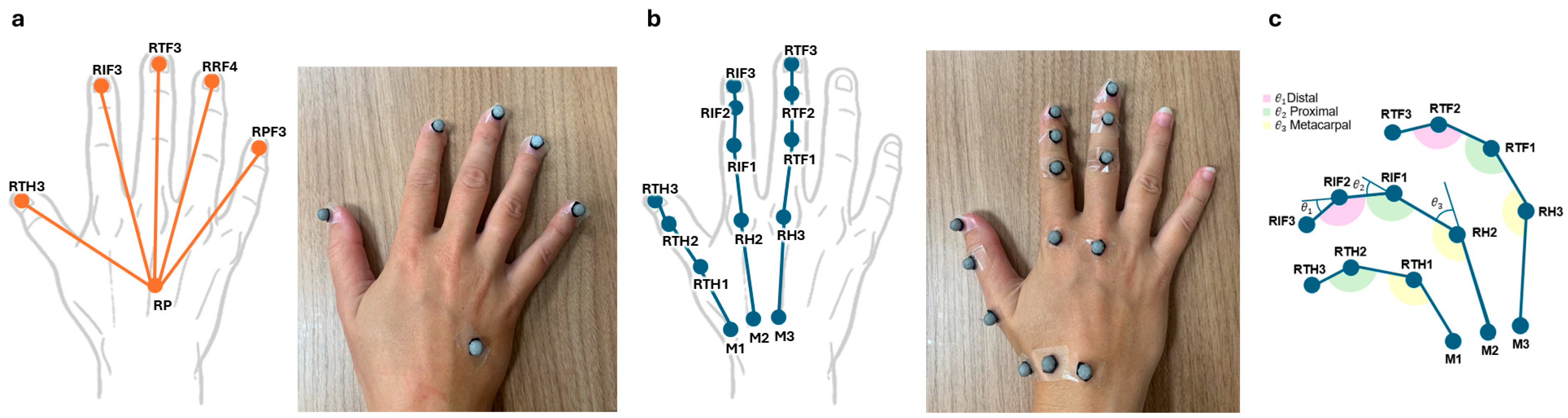
Each subject wore lightweight, retroreflective, spherical, 6.5 mm diameter markers on their hand. Marker placement was performed according to the hand joints tracked by HL2 using the Mixed Reality Toolkit version 2.8.3.0 (MRTK2) and following the recommendations provided in Cook et al. [
27]. In total, we had 6 tracking points, as shown in
Figure 1a, for the tracking of a 2D pattern (Task 1) and 14 points, as seen in
Figure 1b, for the grasping (Task 2) and lateral pinching (Task 3) of objects. Each point was assigned a specific label, and its position in 3D coordinates was recorded.
3.4. Tasks and Experimental Procedures
Task 1 involved tracing a 2D pattern in 3D space with the index fingertip by moving their right arm. It was designed to assess HL2’s fingertip tracking capabilities. The pattern was an infinity symbol, measuring 20 cm in height and 50 cm in width, viewed through HL2 at a distance of 60 cm from the participant’s head and centered at the height of their right shoulder. Participants were instructed to trace the shape using their right index finger while moving their arm and keeping their hand open. They were explicitly instructed to keep their heads still and were informed that this was crucial for ensuring accurate recordings. They could start at any point and trace in any direction at a normal speed but were required to complete the entire pattern. The task was performed only once.
Task 2 involved grasping various common objects with the right hand while maintaining a static position. Some objects were transparent to facilitate marker tracking, as opaque or colored objects could occlude parts of the hand, obstructing the markers. They included a cylinder (13 cm long × 3 cm in diameter), two spheres (8 cm and 12 cm in diameter), a cube (3 cm × 3 cm × 1 cm) and a plug (3 cm in diameter), allowing us to capture the most common types of grasps: cylindrical, spherical, and pinch [
28,
29]. Specifically, the cube is for precision grip with opposite fingers on flat surfaces; the small sphere provides a spherical grasp with flexed fingers encircling the object, while the big sphere requires a power grasp; the plug allows us a pinch grasp with thumb and index finger; the cylinder enables us to study cylindrical grasp with fingers wrapped around the object. The procedure for this task involved grasping each object from the table, positioning it approximately 20 cm in front of the participant’s face for 5 s, and then returning it to its original position. This process was repeated five times for each object, always starting from the same initial position. The objects were always presented and grasped in the same order across repetitions, as the primary objective was to record stable hand configurations. A single data file was generated for each object, containing recordings of all five grasping attempts.
Figure 2a illustrates how the objects were grasped and positioned in front of the participant’s face.
Task 3 involved laterally pinching rectangular objects with both hands while maintaining a static position. Five objects of varying thickness were used, as shown in
Figure 2b, ranging from 2 to 10 cm in increments of 2 cm. The use of both hands in this task was necessary due to the difficulty HL2 faces in accurately detecting the hand’s configuration when markers are present. As a result, markers were placed on only one hand, allowing HL2 to track the hand without markers and VM to track the hand with markers. The markers were placed on the index and thumb fingers, randomly on either the right or left hand across participants, who were instructed and trained to maintain a natural pose and the same symmetrical pinch-posture hand configuration with both hands. The procedure for this task involved pinching each object on the table and keeping a static position for 10 s in front of the participant’s head to allow both the HL2 and VM to correctly capture the hands. The sequence of object sizes was not randomized or counterbalanced, as the fixed order facilitated consistent data capture across repetitions to collect accurate static pinching configurations.
To ensure valid HL2 recording of the hand in Tasks 2 and 3, participants could see a hand mesh through HL2, which overlapped their actual hand during the tasks. A recording was considered valid when participants confirmed that the hand mesh configuration matched their real hand while holding the object and maintaining a static position. Otherwise, the task was repeated.
In all tasks, participants were seated on a chair positioned so that the backrest was 40 cm from the table. The right armrest was aligned with a designated cross mark, indicating the resting position of the right hand, which was used for performing the calibration procedures for both the HL2 and VM. The operational workspace was located directly in front of the participants and was constrained by the field of view of the HL2 device.
Data recording for each task began with the remote initiation of the HL2 recording application. Once the HL2 application started, the VM recording was immediately activated. To facilitate offline synchronization of data from the VM and HL2, participants were instructed to make a quick upward movement with their index finger before beginning each task. This movement was clearly visible and served as a reference point for aligning the two data streams and synchronizing the recorded tracks.
3.5. Data Analysis
3.5.1. Data Preprocessing and Alignment
All data were analyzed using MATLAB r2024b [
30] (the procedural pipeline followed throughout all tasks is illustrated in
Supplementary Figure S1). Initially, the data were stored in various formats; therefore, we standardized the data formats. Data from HL2 were first filtered using a 4th-order Butterworth low-pass filter with a 6 Hz cut-off frequency to reduce noise while preserving useful signal components, avoiding significant distortions, and ensuring accurate and reliable movement analysis. Data from VM were used as stored by its acquisition software, which had already filtered the data with a 4th-order Butterworth low-pass filter and a 6 Hz cut-off frequency before storing it. As a reference for signal filtering, we followed the guidelines described by Carpinella and colleagues [
31], who proposed a standardized protocol for hand kinematic analysis, including recommendations for filtering parameters. Specifically, we applied a low-pass Butterworth filter with the same cut-off frequency as reported by Carpinella, but with a lower filter order to minimize signal distortion.
After filtering the data acquired with the HL2 and VM, both data sets were aligned using a time-shifting procedure based on local maximum detection on the first 5 s of the tracks, using the initial movement of the index finger as a reference.
3.5.2. Task 1 Data Analysis
After the two data streams were successfully aligned in time, the HL2 data in the
and
coordinates were switched to match the reference frame of the VM-acquired data. Since the VM coordinate system is different from the HL2 coordinate system, it was required to overcome this problem prior to comparing data from both systems. One option was to calculate the transformation matrix (rotations
and translations
) that maps HL2’s data to the reference frame of VM; however, the reference frame of HL2 is unknown as it is located inside the device. Instead, an ICP (Iterative Closest Point) algorithm was used to find iteratively the transformation matrix that aligns the 3D data given by the two systems, minimizing the distance between them [
32]. The ICP algorithm has two steps: In the first step, the algorithm finds for each point in the data set of HL2 (
) its closest point in the data set of VM (
) by calculating the Euclidean distance between each pair of points. Since both systems had the same acquisition frequency, and therefore the same number of points, each data point
in HL2 corresponds to one point
in VM with the same index.
The second step consists of applying a rotation
and translation
to minimize the distance
between the corresponding pairs, as follows:
where
is the total number of points.
These two steps are repeated until the error is below a threshold of 0.5 mm. Finally, the rotation
and translation
were applied to the HL2 data to align it to the VM data. Once both datasets were aligned, the average distance error between the HL2 and VM data was computed as
This metric provided an estimate of the positional discrepancy between the two systems. A lower value indicates a higher degree of accuracy in HL tracking, while larger values suggest greater deviations from the VM reference system.
3.5.3. Task 2 Data Analysis
In this task, the joint angles of the index, middle, and thumb fingers were calculated from the distal, proximal, and metacarpophalangeal joints tracked by the HL2 and VM. For HL2, joint angles were computed from the tracked positions of the finger joints, whereas for VM, they were derived from the tracked marker positions, as shown in
Figure 1c.
Before calculating the angles and after the data alignment process, the data were segmented for each object into five sub-tracks, each corresponding to one of the five grasping attempts. To achieve this, we calculated the velocity of one of the markers (specifically, the index fingertip), and the beginning of each movement was identified when the velocity exceeded 3% of the maximum peak velocity, while the end of the movement was similarly determined by a return to below this threshold. This method allowed us to segment each grasping movement for further analysis. Since each sub-track could have slightly different durations, we then applied a 200-sample normalization to standardize them and make the traces comparable across repetitions and subjects. This was achieved using MATLAB’s interp1 function with the spline 3rd-order interpolation method.
After normalizing the data in time, the angles of the three joints of the index, middle, and thumb fingers were calculated for each sample within each sub-track: for both HL2 and VM data, joint angles were computed using vector geometry between tracked points [
33,
34]:
where
and
are the 3D vectors of the points recorded from HL2 and the VM corresponding to the segment between specific anatomical landmarks. The choice of reference points followed standard anatomical definitions of finger joint angles to ensure consistency between systems.
Three joint angles per finger and sub-track were calculated by averaging the angle values for each joint and finger within a sub-track. Finally, the angular error for each joint and finger was calculated as the difference between the average joint angle obtained from the HL2 data and the corresponding angle from the VM data.
3.5.4. Task 3 Data Analysis
The calculus of the pinch span (distance between thumb and index finger) in Task 3 was achieved by subtracting the size of a marker (only in data recorded with VM) and half the thickness of the thumb and index finger pads, ensuring that the calculation was made from the same anatomical location. The finger pad thickness of each participant was measured using a digital caliper. It is worth mentioning that a correct pinch span measurement should correspond to the thickness of the object being laterally pinched.
3.5.5. Statistical Analysis
First, for all the measures computed, the normality of the data distribution was assessed with the Lilliefors Normality Test [
35]. Then, to evaluate the consistency between the reconstructions obtained from the HL2 and the VM, the Pearson correlation coefficient [
36] (in case of normal distribution) or Spearman correlation coefficient [
37] (in case of non-normal distribution) was calculated for the first and second tasks. This statistical measure was used to quantify the degree of linear relationship between corresponding data from the two systems. Specifically, it was applied in Task 1 to assess whether the reconstructed movement traces from HL2 and VM were correlated and in Task 2 to evaluate the correlation between the reconstructed joint angles. Using the correlation across all tasks provided a standardized method to compare the outputs and validate the similarity of reconstructions between the two systems. For Task 3, we conducted a repeated measures two-way ANOVA to test whether there is an interaction between measurement and size, i.e., whether the difference between HL and VM measurements varies with the size of the object. The null hypothesis for the ANOVA was that there is no interaction between the method of measurement (HL2 vs. VM) and object thickness. The alternative hypothesis was that an interaction exists. Then, we finally computed a paired sample
t-test to assess the significance of the observed correlations: in this case, the null hypothesis was that no difference exists between HL2 and VM pinch span for a given thickness, with the alternative being that a difference exists. For all the analyses, the significance level was set at α = 0.05 (MATLAB r2024b default). To complement correlation coefficients, we report the Bland–Altman analysis in
Supplementary Materials, including the mean difference (bias) with 95% confidence intervals, as well as the limits of agreement (LoA) with their corresponding 95% confidence intervals, to provide a more comprehensive statistical picture of agreement between the HL2 and the VM.
4. Results
4.1. Task 1: Finger Tracing of a 2D Pattern in 3D Space
In this task, participants were asked to trace an infinity-shaped path in 3D space with the right index fingertip while moving the arm, as viewed through HL2. This task was designed to evaluate the finger tracking capability of the HL2 compared to that of the VM. By calculating the average distance error between HL2 and VM data tracks across all participants, we assessed the finger tracking capability of the HL2.
Before calculating the distance error, the ICP algorithm reported by Besl and McKay [
31] was used to iteratively find the transformation matrix that aligns the 3D data from the two systems, minimizing the distance between them.
Figure 3 (left panel) illustrates the trajectories recorded by the VM and HL2 systems before alignment. It can be observed that they exhibit a noticeable discrepancy along the depth axis (
y-axis). This misalignment arises from differences in the coordinate system origins of the two tracking systems.
Figure 3 (right panel) shows the trajectories recorded by the VM and the trajectories of the HL2 system transformed by the rotation and translation matrices found by the ICP algorithm. It can be observed that the two trajectories become closely aligned, indicating that the discrepancy introduced by the differing reference frames has been effectively corrected.
Table 1 presents the average distance error across participants between HL2 and VM tracking data for each fingertip of the hand. The distance errors for the thumb, middle, ring, and little fingertips are consistent, averaging around 2.8 mm. The distance error for the index fingertip is higher (3.9 mm), but remains below 5 mm.
This correspondence is further supported by Pearson’s correlation coefficient, as the data were normally distributed. The correlation coefficients were: RTH3 0.99 ± 0.002, RIF3 0.99 ± 0.008, RTF3 0.99 ± 0.001, RRF4 0.99 ± 0.001, RPF3 0.99 ± 0.001. All p-values were equal to 0, indicating statistically significant correlations.
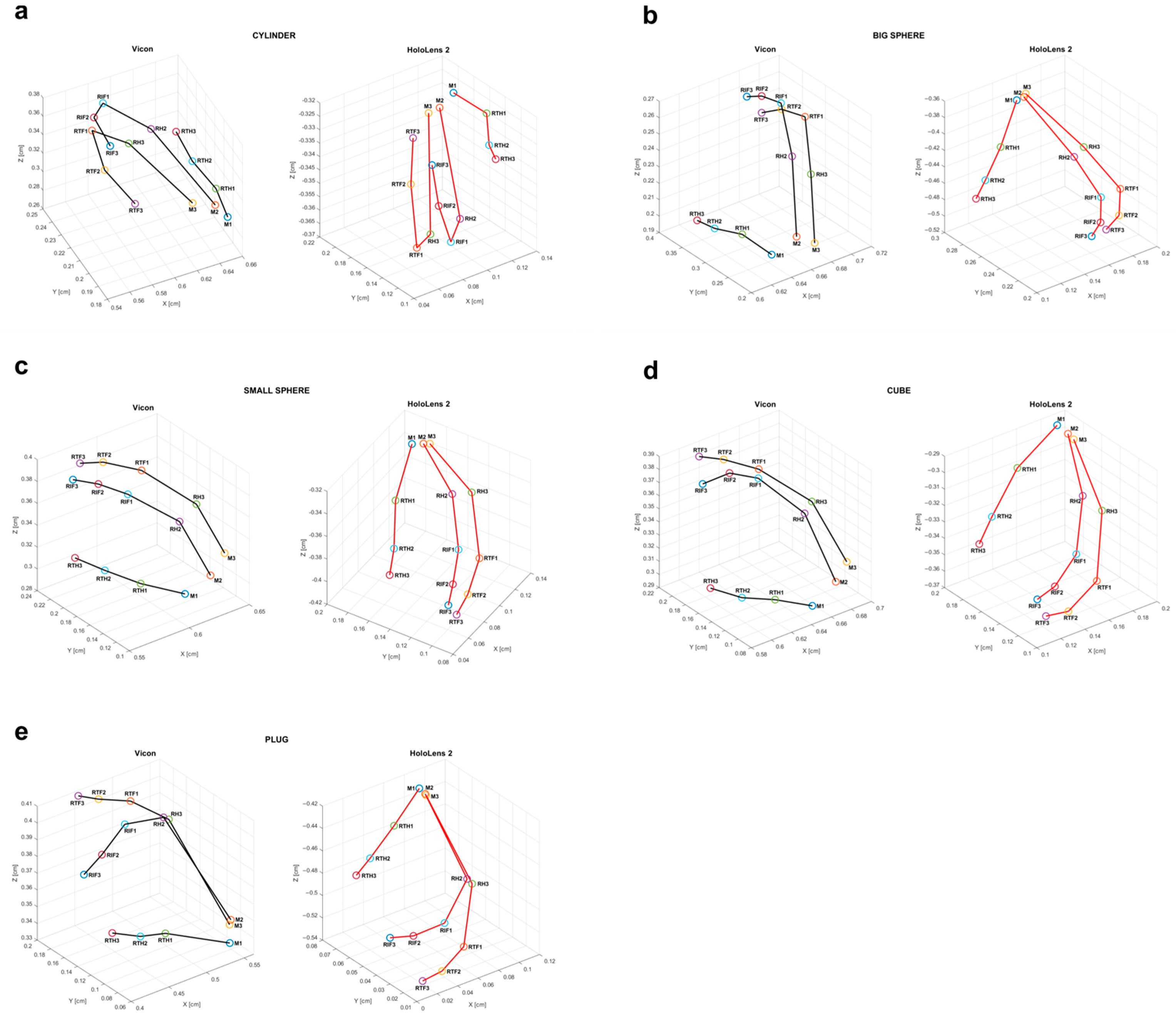
4.2. Task 2: Grasping Common Objects
In this task, participants grasped various common objects, one by one, with the right hand while maintaining a static position (see
Figure 4 for the reconstructed grasp across all objects for a representative subject, shown for both HL2 (red) and VM (black)). The accuracy of HL2 in measuring joint angles was evaluated by calculating the angular error between the angles derived from the data collected by HL2 and VM for each object. All objects were grasped using the thumb, index, and middle fingers, except for the cube and plug, which involved only the thumb and index fingers. Consequently, only the angles of the fingers involved in each grasp were analyzed. The angles for the index and middle fingers were measured at the distal (DIP), proximal (PIP), and metacarpophalangeal (MCP) joints, while for the thumb, the angles were measured at the interphalangeal (IP) and metacarpophalangeal (MCP) joints.
The mean angular joint errors calculated for each grasp and finger are presented in
Table 2. It can be observed that the errors range from 0.3° to 22°, with the largest errors occurring in the IP joint when grasping the small sphere (21.87° ± 0.62), and the smallest in the thumb MCP joint when grasping the big sphere (0.28° ± 0.56). On average, across objects and finger joints, the angular error is 5.36 ± 5.31°. The correlation coefficient between the angle distributions for HL2 and VM revealed that for the small sphere, only the thumb MCP joint angles were not correlated (r = 0.04,
p = 0.61), while the index and middle ones are correlated (
p < 0.01 for thumb IP;
p < 0.0001 for all the others). For the big sphere, all the joint angles calculated correlate (
p < 0.01 for thumb IP and index DIP and
p < 0.005 for all the others) except for the middle PIP (r = −0.12,
p = 0.82). The cylindrical grasp presented no correlation in both thumb IP angle (r = 0.09,
p = 0.21) and PIP index angle (r = −0.05,
p = 0.45). Finally, the plug presented no correlation for the thumb IP angle (r = 0.01,
p = 0.89) and the index MCP angle (r = 0.10,
p = 0.16), while for the cube grasp, there is always a significant correlation (
p < 0.0001 for all five angles). Since not all distributions were normal, correlation types were selected accordingly, with Pearson’s correlation applied when normality was satisfied and Spearman’s correlation otherwise.
4.3. Task 3: Lateral Pinching of Objects
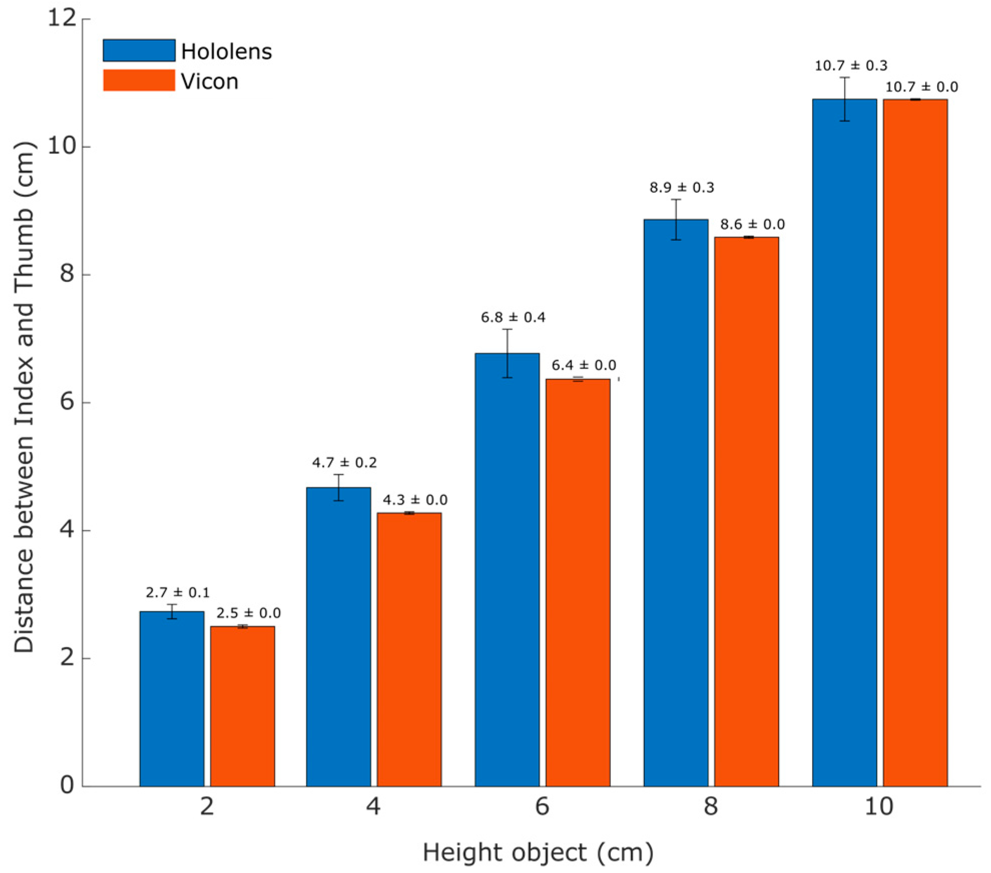
In this task, participants gripped objects of varying heights laterally using their index and thumb fingers. The pinch span (distance between the tip of the index finger and the thumb) was calculated from data collected by both HL2 and VM, and the results were compared to evaluate HL2’s accuracy in measuring lateral pinch span.
As shown in
Figure 5, the pinch span measured by HL2 is close to that measured by the VM with the largest difference observed for the object with 6 cm thickness (6.77 ± 0.38 mm for HL2 and 6.36 ± 0.03 mm for VM) and the smallest for the object with 10 cm thickness (10.75 ± 0.34 mm for HL2 and 10.74 ± 0.01 mm for VM). Notably, the pinch span calculated from HL2 data improves as object thickness increases, suggesting that HL2 performs better with larger objects (see
Table 3). For thinner objects (2–4 cm), the error was small and consistently positive, as indicated by narrow confidence intervals. For thicker objects (6–10 cm), the increased variability resulted in wide confidence intervals crossing zero, suggesting no clear systematic error at these thicknesses. The two-way ANOVA with repeated measures confirmed a significant interaction between the type of measure (HL2 vs. VM) and the size of the grasped object: F(1, 3) = 644.23,
p = 0.00013,
= 0.995.
The Lilliefors test showed that all the data were normally distributed. The two-way ANOVA with repeated measures confirmed a significant interaction between the type of measure (HL2 vs. VM) and the size of the grasped object: F(1, 3) = 644.23, p = 0.00013, = 0.995. No statistically significant difference (h = 0) was observed between the pinch span measurement from HL2 and VM recordings for all objects with different thicknesses. Specifically, the statistical paired sample t-test results for each object thickness were as follows: 2 cm (p = 0.32, t(3) = −1.16 ± 0.004, CI [−0.009, 0.004]), 4 cm (p = 0.27, t(3) = −1.37 ± 0.006, CI [−0.013. 0.005]), 6 cm (p = 0.39, t(3) = −1.01 ± 0.008, CI [−0.017, 0.009]), 8 cm (p = 0.06, t(3) = −2.97 ± 0.002, CI [−0.006, 0.0002]), and 10 cm (p = 0.99, t(3) = −0.02 ± 0.004, CI [−0.007, 0.007]).
5. Discussion
The findings of the present study offer valuable insights into the hand-tracking performance of the HL2, demonstrating its accuracy and reliability in capturing hand kinematics by benchmarking it against the high-precision VM. By assessing both general hand movements and object-grasping tasks, we aimed to capture the strengths and limitations of the HL2’s tracking capabilities in real-world augmented reality (AR) interactions.
Related to the HL2’s fingertip tracking capabilities during hand movement tracing, the results revealed a strong correspondence between the HL2 and VM traces, as indicated by the Euclidean distance measurements, suggesting that the HL2 hand-tracking system provides relatively precise positional data. As shown in
Table 1, the tracking errors for all fingertips remain within a few millimeters, with values consistently below 4 mm. Additionally, the high Pearson correlation coefficients (approximately 0.99 for all fingers) confirm a near-perfect correspondence between the two systems. The statistical significance of these correlations (
p = 0) further reinforces the reliability of HL2’s tracking performance. The slight differences observed in finger tracking errors may result from factors such as inconsistent sensor coverage, occlusion effects, or variations in hand morphology among participants. As with all tracking systems, the similarity between the participant’s hand and the underlying model or mesh used by the system plays a crucial role in determining measurement accuracy. Therefore, individual differences in hand morphology, such as hand size and finger length, are likely to influence the precision of tracking. These anatomical variations may lead to suboptimal mesh fitting and contribute to measurement errors. While these findings highlight the high spatial accuracy of HL2, they do not account for potential limitations related to temporal resolution or tracking latency, which could impact real-time applications. Notably, the spatial accuracy observed in the present study is considerably higher than that reported in previous works, such as [
17,
25], where tracking errors were approximately 15 and 20 mm, respectively. These differences may be attributed to variations in the nature of the spatial tasks, with the current study focusing on 3D hand movement tracing, in contrast to the 2D surface tracking used in [
25]. Additionally, differences in the reference tracking systems may have contributed, as this study used a Vicon motion capture system, while [
25] employed a touchscreen-based system and [
17] relied on an OptiTrack setup.
The results obtained for angular joint errors during the grasping of various common objects highlight the overall reliability of the HL2 tracking data for calculating hand kinematic parameters. The average angular joint errors generally remained moderate (about 5°), indicating a reasonable level of accuracy for most grasped objects. The correlation coefficients further support this, showing strong correlations for most joint angles, particularly in objects such as the small and large spheres. However, discrepancies arise in specific cases, such as the lack of correlation for thumb angles in the small sphere grasp and the middle intermediate angle in the big sphere task. These inconsistencies could be attributed to variations in how participants positioned their fingers and differences in hand dimensions, which may introduce differences in the tracking position of the joints. In addition, for joint angle measurements that showed no correlation (e.g., thumb IP), we attribute this to the presence of reflective markers on participants’ hands, which may have interfered with the HL2’s ability to correctly fit the hand mesh and thereby reduced tracking accuracy.
The cylindrical grasp proved to be the most challenging for the HL2 system, likely due to finger occlusion issues. Indeed, the tracking system struggled to differentiate individual finger movements when they overlapped, leading to a lack of correlation for the thumb and index intermediate joints. Similarly, the plug grasp exhibited no correlation for the thumb intermediate and index metacarpal angles, further demonstrating the HL2’s limitations in handling complex hand postures where multiple fingers are closely positioned. In contrast, the cube grasp yielded strong correlations across all angles, suggesting that the HL2 system performs better in situations where finger positions are more distinct and easily trackable.
The results from measuring the lateral pinch span while holding objects of varying thicknesses show that HL2 performance is comparable to that of the VM, with accuracy in calculating the pinch span improving as the object thickness increases. This suggests that the HL2 performs better with larger objects, likely because such objects provide clearer spatial references for hand tracking and reduce occlusion-related errors. This further supports the notion that while HL2’s hand-tracking system is reliable in many scenarios, its performance is highly dependent on the nature of the grasp task and on the object being manipulated. These findings highlight the need for improved tracking algorithms that can better handle overlapping fingers and account for individual hand size differences to enhance MR interaction fidelity.
The high accuracy of HL2 in tracking hand position and measuring kinematic parameters, such as joint angles and lateral pinch span, carries significant implications. As a portable system, HL2 shows potential as a tool for evaluating hand movement during functional activities [
38,
39] and analyzing human grasping capabilities under various conditions [
40]. From a practical perspective, the errors identified in this study suggest that HL2 can be effectively employed in realistic scenarios. Specifically, concerning object grasping, an angular error of approximately 5° falls within a functional tolerance for coarse grasping tasks, allowing successful execution without significant impact on performance. In such cases, the HL2 offers notable advantages in terms of portability and usability compared to traditional motion capture systems such as VM. However, for tasks that demand higher precision (such as microsurgery), such errors may be unacceptable. In these contexts, the HL2 alone (as well as similar commercial systems) may not provide sufficient tracking accuracy, and the integration of additional correction algorithms or complementary sensors becomes necessary. Our results support this conclusion: in Task 3, we quantitatively observed that grasping accuracy improves as the size of the object increases, confirming that large-object grasping remains functional, while fine grasping presents greater challenges. This highlights that, depending on the application, a gold-standard system like Vicon may be preferable over a more portable but less precise solution. Furthermore, the spatial error observed (approximately 3 mm) indicates that HL2 hand tracking performs comparably to the VM in tasks involving large movements or interactions with sizeable virtual objects but loses accuracy in fine movements or with small objects. Consequently, the HL2 proves to be a suitable option for mixed-reality interactions involving gross motor tasks, whereas systems like the VM remain the preferred choice when higher precision in fine motor tracking is required.
To our knowledge, this is the first study that assesses the accuracy of HL2 in tracking hand position and measuring kinematic hand parameters using the VM as a benchmark. This comparison was necessary due to the growing development of applications and research that make use of HL2. Our findings suggest a potential, albeit less precise, correlation between the results obtained from these two different motion detection systems.
6. Conclusions and Future Directions
The results of the present study indicate that the HL2 exhibits millimeter-level errors compared to the VM in both Task 1 and Task 3, and additionally, the reconstructed grasping positions from Task 2 from both systems show a strong correlation and an average error of 5°, suggesting that the HL2’s hand-tracking system demonstrates good accuracy. These findings highlight the potential of HL2 for precise hand tracking in MR applications while also emphasizing the need for further refinements to minimize small positional errors and ensure optimal tracking across different hand configurations and motion patterns.
In conclusion, the HL2 system offers markerless tracking, which, although slightly less precise, is still comparable to motion capture systems. The pace of technological advancements in MR is expected to accelerate in the coming years [
41]. Future research will focus on creating more ecologically valid scenarios within experimental procedures, leveraging the possibility to integrate perceptual stimuli into mixed reality environments. Additionally, future work could explore the integration of advanced optimization algorithms and embedded system technologies to further enhance precision and efficiency in applications such as hand tracking and mixed-reality interaction [
42,
43]. Similarly, real-time processing on embedded platforms may support the development of more reliable and accurate tracking systems, for example, to refine real-time hand pose estimation and gesture recognition [
44].


 ,
, 


