Article

Methods for Testing Meniscal Repair Using a 3D-Printed Meniscus

1
School of Medicine, Uniformed Services University of the Health Sciences, Bethesda, MD 20814, USA
2
Walter Reed National Military Medical Center, Bethesda, MD 20814, USA
3
4D Bio3 Center for Biotechnology, Department of Radiology and Radiological Sciences, Uniformed Services University of the Health Sciences, Bethesda, MD 20814, USA
4
The Geneva Foundation, Tacoma, WA 98402, USA
*
Author to whom correspondence should be addressed.
Appl. Biosci. 2024, 3(1), 102-122; https://doi.org/10.3390/applbiosci3010007
Submission received: 29 November 2023 / Revised: 16 January 2024 / Accepted: 4 February 2024 / Published: 6 February 2024
(This article belongs to the Special Issue Anatomy and Regenerative Medicine: From Methods to Applications)

Abstract

:
Torn and damaged menisci resulting from trauma are very common knee injuries, which can cause pain and mobility limitations and lead to osteoarthritis. Meniscal injuries can require surgery to repair the tissue damage and restore mobility. Here we describe the biomechanical testing of a 3D-printed meniscus to illustrate methods to determine if it has the strength and durability to effectively repair meniscal tears and restore knee biomechanics. This work was designed to demonstrate the steps needed to test novel meniscus repair devices prior to moving toward animal testing. The first testing step determined the ability of the 3D-printed meniscus to withstand surgical fixation by measuring the suture pull-out force. We show that vertical 2/0 silk or Fiberwire sutures need an average of 1.4 or 1.8 N, respectively, to pull through the meniscus, while horizontal sutures need only 0.7 and 1.2 N, respectively. The next step measured the compressive strength of normal, damaged, and repaired porcine meniscus tissue. Here, we show that meniscectomy decreased the stiffness of meniscus tissue from 26.7 ± 0.85 N to 7.43 ± 0.81 N at 25% strain. Menisci repaired with the 3D-printed tissue restored 66% of the measured force at 25% strain. The final step measured the contact pressures and areas in an ex vivo porcine knee before and after meniscal repair was made with the 3D-printed meniscus tissue. The example 3D-printed meniscus was successfully sutured into the porcine knee joint but failed to restore normal knee contact pressures. This work demonstrates the need for an iterative biomechanical testing process of biomaterial development, 3D-printing optimization, and knee kinematics to develop a durable and functional meniscus repair device. In summary, the methods described here serve as a guide for the functional evaluation of novel meniscus repair devices.

1. Introduction

The meniscus is the main stabilizing tissue of the knee that facilitates proper tracking and movement of the knee joint. Human menisci are two wedge-shaped, semilunar discs within the knee joint that cushion the impact between the lateral/medial femoral condyles and the tibial plateau during normal leg movement [1]. Injury to the meniscus impairs proper joint function and is associated with pain and typically leads to progressive knee osteoarthritis. Tears of the meniscus resulting from trauma or repetitive abnormal stresses are among the most commonly diagnosed knee injuries, with a yearly incidence of approximately 61 per 100,000 people [2,3]. Military service members are particularly vulnerable, as they exhibit ten times the incidence of meniscal injury compared with civilians [4,5]. Furthermore, participating in sports such as soccer are risk factors for sustaining acute meniscal injury, while degenerative meniscal injury is associated with age > 60, being male, and work-related physical activities like kneeling [6].
Meniscal injuries often require surgical intervention to repair, restore basic functionality, and relieve pain. Nearly 1 million meniscal surgical procedures are performed annually in the United States [2,7]. The surgical treatment varies depending on the type of damage present and includes partial meniscectomy, repair, or reconstruction using implants or allograft transplants [8]. Drawbacks to a meniscal allograft transplant include limited clinical success [9] and the requirement for a closely size-matched donor. Tissue engineering offers promise for new regenerative medicine therapies, including meniscal replacement devices. Three-dimensional (3D) printing, which deposits “ink” layer by layer, is becoming a more common method of producing scaffolds and tissue-engineered devices due to the ability to precisely control print-head tool paths and to fabricate the architectural geometry of an object through tailored computer-aided design (CAD) [10,11,12]. In comparison with more conventional mold-casting processes, CAD methods and 3D printing enable greater architectural complexity and rapid prototyping for 3D structures composed of hydrogels or synthetic polymers, which can also be laden with live cells (bioprinting) [10]. Bioinks used for 3D bioprinting are shear-thinning and typically have low viscosity, which makes it difficult to maintain shape fidelity during printing. The use of fluid gel support baths made of gelatin and agarose facilitate much improved hydrogel shape fidelity [13,14,15]. Several recent studies describe anatomically shaped meniscal devices produced by 3D printing, including ones made from biologically relevant collagen hydrogels [16,17,18,19,20,21,22,23,24,25]. Finally, tissue-engineered menisci have been produced in ways ranging from homogenous hydrogels [26] to thermoplastic scaffolds made with electrospinning and thermoplastic scaffolds with radial and circumferential fibers [27].
Our group recently reported a bioprinted meniscal repair device that simulates the composition and architecture found in human meniscal tissue [25]. In the native meniscus, fibers composed of predominantly collagen type I are oriented circumferentially [28], imparting tensile strength and transmitting compression forces into hoop stress, while radial collagen fibers, arranged perpendicular to the meniscal plane, confer structural integrity and stiffness to the tissue under load-bearing conditions [29]. In our bioprinted meniscus, we used alternating layers of circumferential and radial extrusions of a custom bioink composed of collagens type I and type II and chondroitin to recapitulate this anatomical structure. This combination of the ink along with the design of the 3D-printed meniscus has been shown to lead to excellent biocompatibility [25].
For a meniscal repair device to be useful, it must withstand fixation processes like suture placement, and it must be stiff enough to support compressive loading in the knee joint. The inability to hold sutures would render the device ineffective for meniscal defect repair. There are numerous studies assessing the suture pull-out force of tissues with vertically oriented testing apparatuses [30,31,32,33]. Sutures composed of ultra-high molecular-weight polyethylene such as Fiberwire and Tigerwire typically perform well for meniscal repairs [31,34]. Several previous studies have developed methods to test meniscus strength in ex vivo specimens using a mechanical test system and sensor capable of recording spatial-force data. These studies provide similar specimen preparation approaches, disarticulation techniques, and compression methods but do not capture critical steps such as specimen mounting and mechanical test system calibration that are essential for collecting reliable data [35,36,37]. Thus, there is no single source that helps to detail methods and protocols for a test set up and the subsequent evaluation of meniscal repair devices.
In this paper, we describe biomechanical testing protocols for an acellular version of the 3D-printed meniscus to evaluate whether it has the strength and durability for the effective repair of meniscal tears and the restoration of knee biomechanics. Our 3D-printed meniscus was used as an example to demonstrate generalizable methods for testing meniscus repair devices. The first stage of testing evaluated the ability of the 3D-printed meniscus to handle surgical fixation by measuring the suture pull-out force. The second stage measured the compressive strength following fixation of the bioprinted meniscus into isolated porcine meniscus tissue. The final stage evaluated the performance of the meniscal repair in an ex vivo porcine knee using contact pressure readings. In our example, we demonstrate that the bioprinted meniscal tissue was successfully implanted into the knee joint but failed to restore normal knee contact pressures. This work was designed to demonstrate the steps needed to test novel meniscus repair devices, and it highlights the need for an iterative process of biomaterials development, 3D-printing optimization, and knee biomechanical studies prior to starting live-animal studies. Though the data presented is just the beginning in advancing the usability and functionality of the 3D-printed meniscus, we established start-to-finish methods for testing meniscal repair. This is not only useful for our future testing but will also be applicable for the evaluation of many types of meniscus repair devices and approaches.

2. Materials and Methods

2.1. 3D-Printed Meniscus Fabrication

2.1.1. Preparation of Ink

The 3D-printing ink was prepared using methods established in prior work [25]. We prepared the first of three stock solutions by combining 5 mL methacrylate bovine collagen type I (Advanced BioMatrix, Carlsbad, CA, USA) and 918 μ L chicken sternal collagen type II (Sigma, St. Louis, MO, USA). Both collagen components were solubilized to 25 mg/mL in 40 mM acetic acid before mixing in syringes. The second stock solution combined 833 μ L of 10× neutralization solution and 177 μ L of 1 M HEPES buffer pH 9.5. The third stock solution combined 77 μ L methacrylate chondroitin sulfate (CS; Nanosoft Polymers, Winston-Salem, NC, USA), dissolved to 100 mg/mL in phosphate-buffered saline (PBS), and 220 μ L of lithium phenyl-2,4,6-trimethylbenzoylphosphinate (LAP; Advanced BioMatrix, Carlsbad, CA, USA), dissolved to 17 mg/mL in PBS. We mixed the three stock solutions in order of their listing to create the final ink mixture. Because an acellular ink was to be used for these tests, we added 465 μ L of PBS as a substitute for the cell suspension volume to ensure the correct final ink concentration. We transferred the ink to amber-colored syringes to prevent UV crosslinking, removed air using centrifugation, and stored the syringes at 4 °C to prevent gelling. Rheological assessment showed that the meniscus ink was shear-thinning and extrudable [25]. In addition, meniscus tissue bioprinted using this ink with the addition of stem cells showed excellent biocompatibility [25].

2.1.2. 3D Printing

All printing was performed using a commercial bioprinter (BioX; Cellink, Gothenburg, Sweeden). The chilled ink was transferred into 3 mL syringes with 22-gauge blunt-tipped needles compatible with the temperature-controlled print-head held at 10 °C. The BioX used a meniscus gcode printing file that prints in alternating circumferential and radial layers similar to the internal anisotropy of native meniscus. Ink was extruded in a support bath of sheared 0.55% Low EE Agarose (Sigma, St. Louis, MO, USA) in PBS known as SLAM (suspended-layer additive manufacturing) printing [13] which is necessary to maintain print shape fidelity while gelling. The SLAM support was pre-warmed in an incubator to 37 °C and kept at 37 °C using a heated print bed. We used a print-head speed of 9 mm/s and an extrusion pressure of 45–55 kPa, as established in prior work. The exact pressure was adjusted to ensure that approximately 2 mL of ink was dispensed for a completed print. The meniscus design dimensions were an outer radii of 40 mm, a radial thickness of 10 mm, and a height of 7.6 mm.

2.1.3. Post-Print Processing

After extrusion, the meniscus was allowed to rest on the heated print bed for 5 min to allow for more complete gelling and to prevent damage during transfer out of the BioX-enclosed print space. The printed meniscus was then placed in a 37 °C incubator for 30 min. The meniscus was then removed from the incubator, and excess SLAM support was removed with a pipette to increase UV exposure to the meniscus in subsequent rounds of crosslinking. Crosslinking was performed with 405 nm light in a FormCure (Formlabs, Somerville, MA, USA) UV chamber in 5 min increments. Prior work with rheology demonstrated that light-indued crosslinking occurs within 1 min, but due to opaqueness of the residual SLAM and of the gelled ink, crosslinking times were extended [25]. Between each exposure, additional SLAM was removed by PBS washing. After a total of 15 min of exposure, the meniscus was washed with PBS and stored at room temperature.

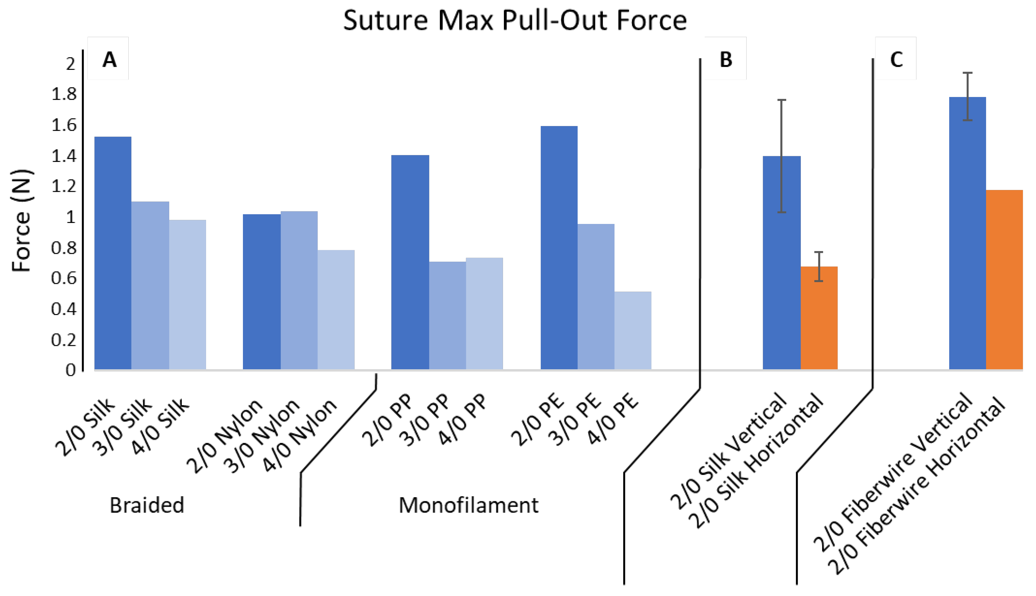
2.2. Suture Pull-Out Force

2.2.1. Custom-Built Test Apparatus

As a first step in evaluating the effectiveness of the 3D-printed meniscus for defect repair, suture mechanics were assessed by applying forces simulating surgical repair with the UniVert Mechanical Test System (CellScale, Waterloo, ON, Canada). A custom-built test apparatus was designed to translate the vertically oriented UniVert tension sensor to measure the horizontal pull-out force. A two-part testing apparatus was designed in Autodesk Inventor CAD and 3D-printed using Formlabs Form 2.
The first part (HOLDER) (Figure 1A) was designed to mount directly onto the base of the UniVert and provide a platform to hold the 3D-printed meniscus during testing. The platform has an outer curved barrier matching the 40 mm outer radius of the meniscus. This curved barrier was designed with notches to allow the interrupted sutures to pass through. The 2 mm notch spacing also allows suture knots to pass through unimpeded during testing. The barrier was also designed to be 2 mm taller than the meniscus, i.e, 10 mm total height, which helped to prevent the 3D-printed meniscus from flipping when the horizontal force was applied.
The second part (SLIDER) (Figure 1B) was designed to attach to the HOLDER and provides a mount for a rotating shaft that translates the vertically oriented tension sensor to measure the horizontal pull-out force. We built the rotating shaft from a steel-alloy linear-motion shaft (McMaster-Carr, Elmhurst, IL, USA) and two mounted shielded steel ball bearings (McMaster-Carr). The shaft helps to minimize friction during the 90-degree transition by providing a freely rotating and smooth suture interface. Sutures were attached to the vertically positioned tension sensor and passed under the rotating shaft to be directed horizontally toward the meniscus. The vertical position of the shaft is adjustable using setscrews to allow the suture to remain horizontal regardless of the height at which it exits the meniscus.

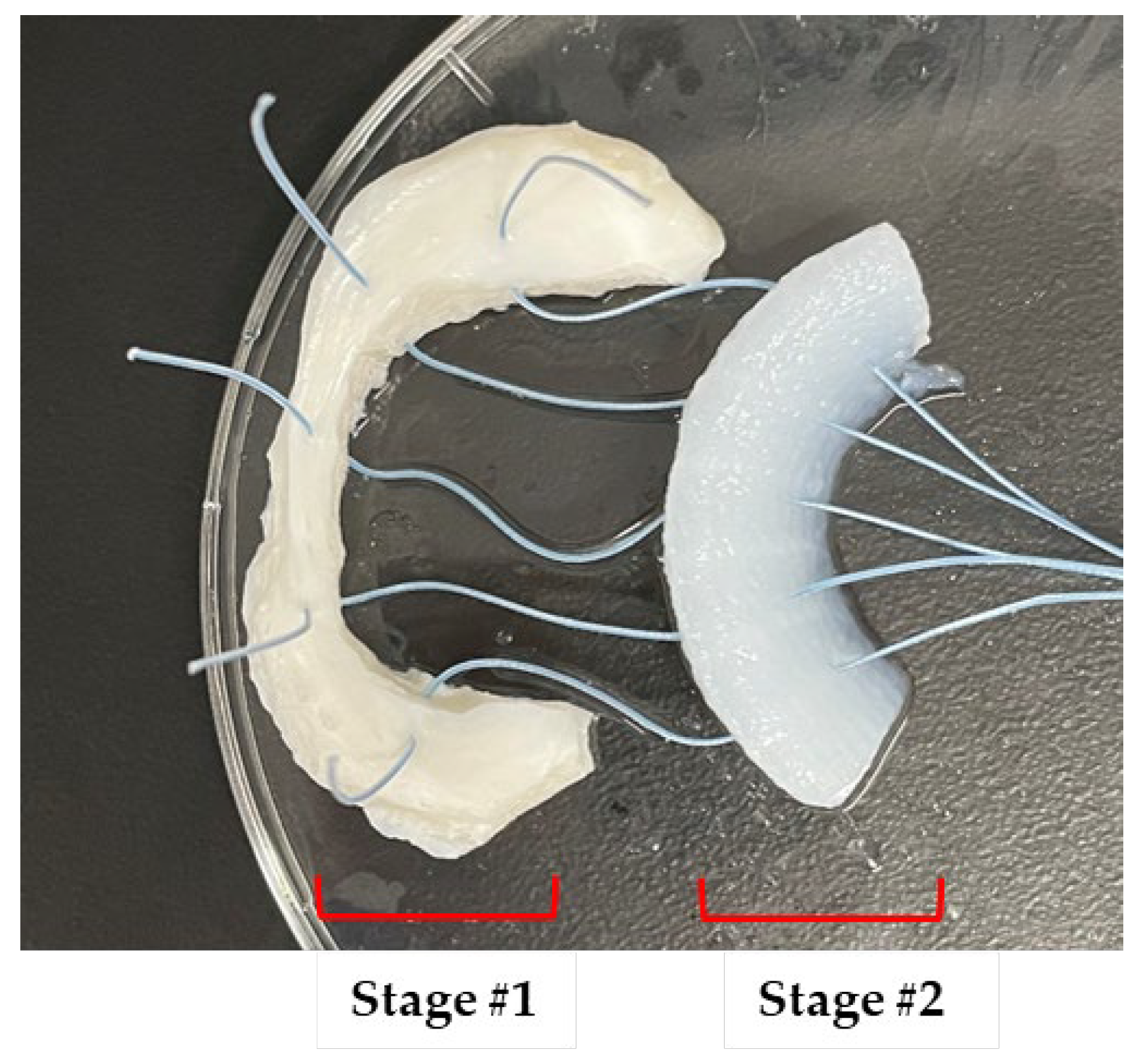
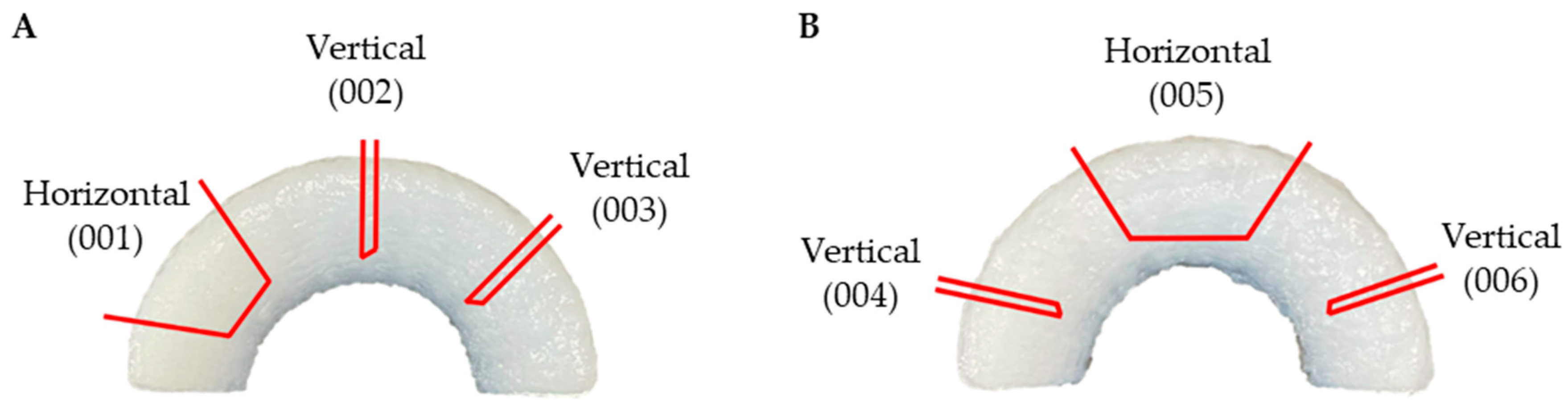
2.2.2. Vertical and Horizontal Suture Placement and Type

Vertical and horizontal simple interrupted sutures were placed to determine if the printed meniscus would be able to withstand basic suturing and to assess the suture pull-out force. Both techniques were investigated to fully capture interactions due to the unique internal architecture of the 3D-printed meniscus. Vertical simple interrupted sutures were placed starting from outside inferior aspect of the meniscus, approximately 3 mm from the bottom, directed inward. The suture was then re-passed superiorly and in plane with the initial pass, approximately 5 mm from the bottom. The vertical suture was completed by applying tension and tying a surgical knot secured to the outer radius of the meniscus. The suture tails extended from this knot to the pull-out testing apparatus.
Horizontal simple interrupted sutures were placed starting from the outside, approximately 4 mm from the bottom of the meniscus, directed inward. The suture then re-entered the meniscus approximately 6–8 mm directly horizontally to the initial entry. As with the vertical suture, the horizontal suture was completed with a surgical knot with tails extending to the testing apparatus.
We initially evaluated silk, nylon, polypropylene, and polyethylene sutures, which are non-absorbable braided and monofilament subtypes. Each suture type was evaluated at the 2/0, 3/0, and 4/0 sizes. After the conclusion of the initial suture pull-out testing, 2/0 Fiberwire (Arthrex, Naples, FL, USA) was used for the final vertical and horizontal pull-out data. The Fiberwire suture was then carried over to the remaining experiments in this body of work as it is most commonly used by orthopedic surgeons during meniscus repair [38].

2.2.3. Pull-Out Testing

All sutures were passed through the 3D-printed meniscus, looped under the rotating shaft, and attached to the tension sensor for pull-out force measurement. We removed most of the slack by raising the tension sensor while being careful to not pre-tear the meniscus before testing. Then, using a pull-out velocity of 0.1 mm/s and a total displacement of 20 mm, sutures were pulled completely through the 3D-printed menisci.

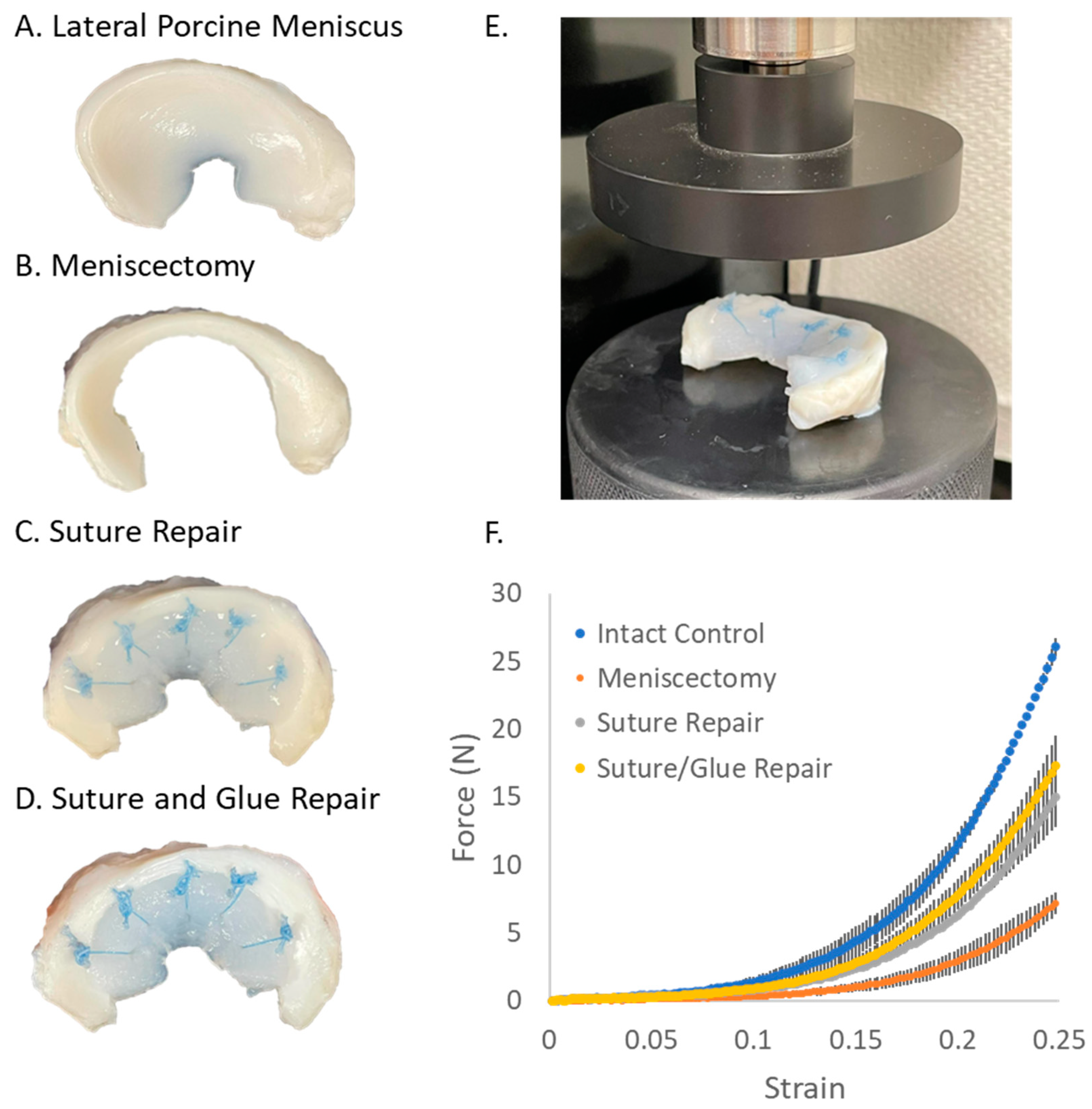
2.3. Compression Testing in Isolated Porcine Menisci

2.3.1. Isolated Porcine Meniscus Preparation

Isolated porcine meniscus tissue was obtained from a commercial vendor (Innovative Research, Novi, MI, USA). Lateral and medial menisci were both provided with loose tissue from the joint capsule still attached. The loose tissue was dissected off the exterior of the meniscus using a scalpel and hemostat, and the cleaned menisci were weighed and measured. Measurements included the X-dimension, Y-dimension, Z-dimension, and R-average. The R-average was calculated by measuring the meniscus radial thickness in three separate locations. Finally, menisci were stored in 50 mL conical tubes in a solution of PBS and penicillin/streptomycin/amphotericin antibiotic solution at a 1:100 dilution.

2.3.2. Isolated Porcine Meniscus Compression Testing

The lateral porcine meniscus was chosen as its physical dimensions are more similar to the 3D-printed meniscus than the medial side. The porcine meniscus was blotted dry to prevent slippage on the flat platen during compression. The porcine meniscus was then positioned on the flat base plate of a UniVert tester, and the top plate was lowered until it was just touching the meniscus. The lowered top-plate’s recorded height above the baseplate corresponded to the Z-dimension measurement performed in the prior section. The porcine meniscus was compressed uniaxially to 25% of its original height for 60 s. This value was chosen based on publications where the applied strains ranged from 12% to 30% [39,40,41]. All subsequent testing used these same compression parameters. After the control testing was completed, the meniscus was returned to the PBS and antibiotic storage solution and allowed to rest for 15 min. Then, using a surgical marker, the meniscectomy border was marked at 3 mm from the outer border and spanning 1.5 cm of tissue centered around the lateral body of the meniscus. The border was then tapered internally to preserve the anterior and posterior horns. The 3 mm measurement from the outer border ensured that the meniscectomy extended to the vascularized region of the meniscus called the “red–red zone”. A scalpel was used to remove the marked tissue, creating the meniscectomy, and the meniscus was compressed. Using a tissue marker and calipers, a section of intact 3D-printed meniscus was cut to serve as the repair implant. The natural outside edge of the 3D-printed meniscus was utilized so only one cut had to be made in the 3D-printed implant. The implant was then placed in the meniscectomy site in complete contact with the surrounding porcine meniscus tissue without altering the overall shape of the meniscus.
A tissue marker was used to mark the locations of five vertical sutures. The first mark was placed in the center of the meniscectomy, then marks were made on either side with a 3mm spacing. Then, 2/0 Fiberwire vertical interrupted sutures were placed at each mark. As a precaution to avoid damaging the 3D-printed implant while suturing, the procedure was performed in a staged approach, suturing through the porcine meniscus first followed by the 3D-printed meniscus (Figure 2). First, the needle was driven through, starting superiorly at the site marked in the red zone of the porcine meniscus and coming out at approximately 3 mm from the bottom of the meniscus, aimed inward toward the implant. The suture was pulled through, leaving a 3 cm tail. This method was repeated for all five marked sites. The 3D-printed meniscus implant was then positioned several centimeters from the meniscectomy in the correct orientation. Starting with the suture in the center of the meniscectomy, the first suture was passed 3 mm from the bottom up through the body of the implant superiorly. This method was repeated for the remaining sutures. At this point, there were still several centimeters of suture between the porcine and 3D-printed menisci. The sutures from the porcine meniscus’s side were alternately pulled out to reduce the space. Once the 3D-printed meniscus implant was fitted within the meniscectomy, the sutures were tied and trimmed, and the meniscus was compressed again. Lastly, 1 mL of 3D-printing ink was manually extruded from a syringe along the superior and inferior interface to serve as a tissue adhesive. The sample was then placed in a 37 °C incubator to allow the liquid ink to solidify. Then, the sample was placed in the FormCure for a total of 15 min for crosslinking followed by compression testing.
Compression data was graphed as force vs. strain. Strain was calculated as z / z , where z is the vertical displacement of the plate as it moves downward, and z is the original distance between the bottom and top plates. While it is common to plot stress (force divided by surface area) vs. strain, we used force due to the non-flat meniscus surface where, with increasing strain, the meniscus surface area in contact with the platen also increases. Since the same sample (plus and minus repair) was compressed each time, the strain-induced surface-area change is approximately the same during the compression cycle, and this allows the samples to be compared.

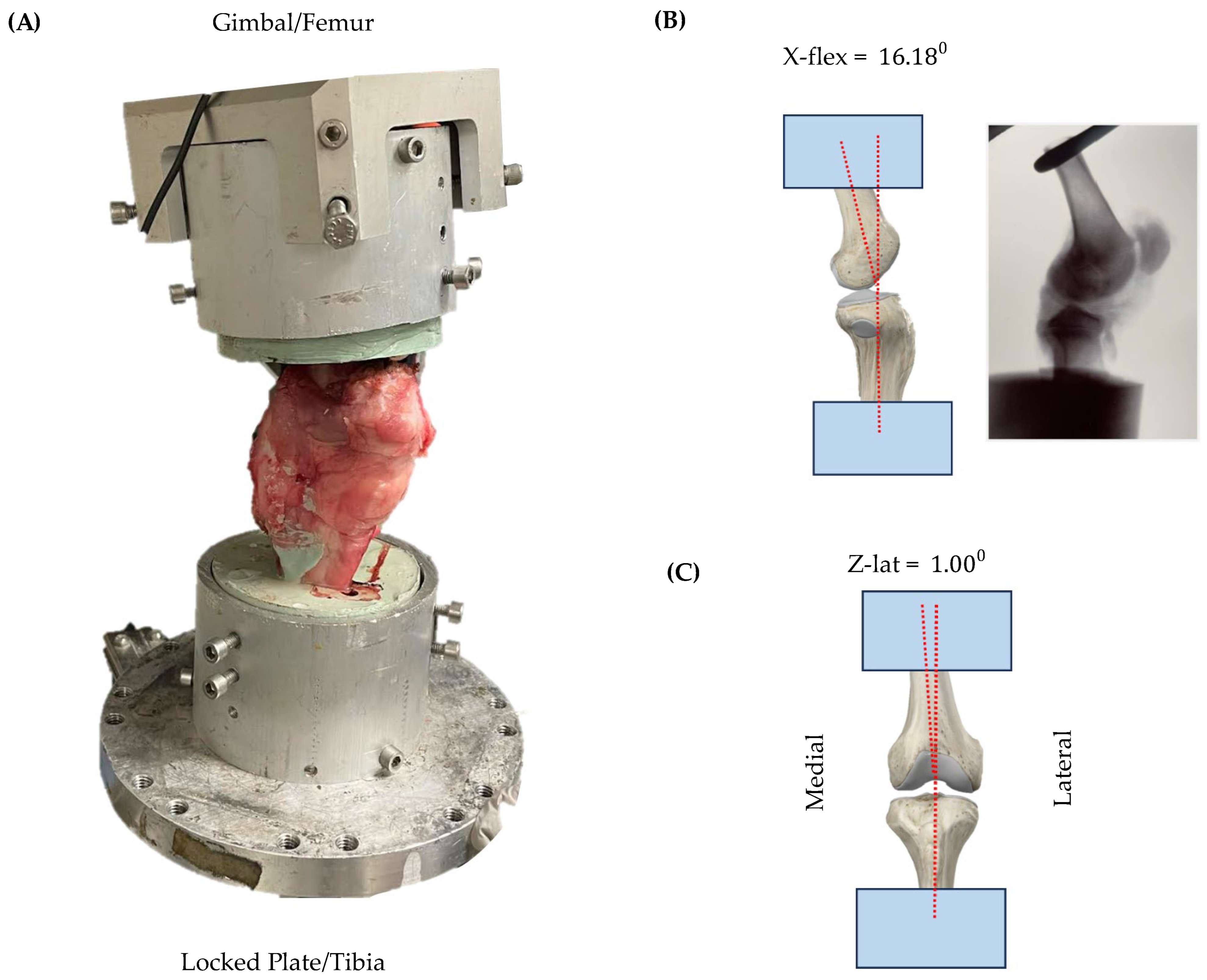
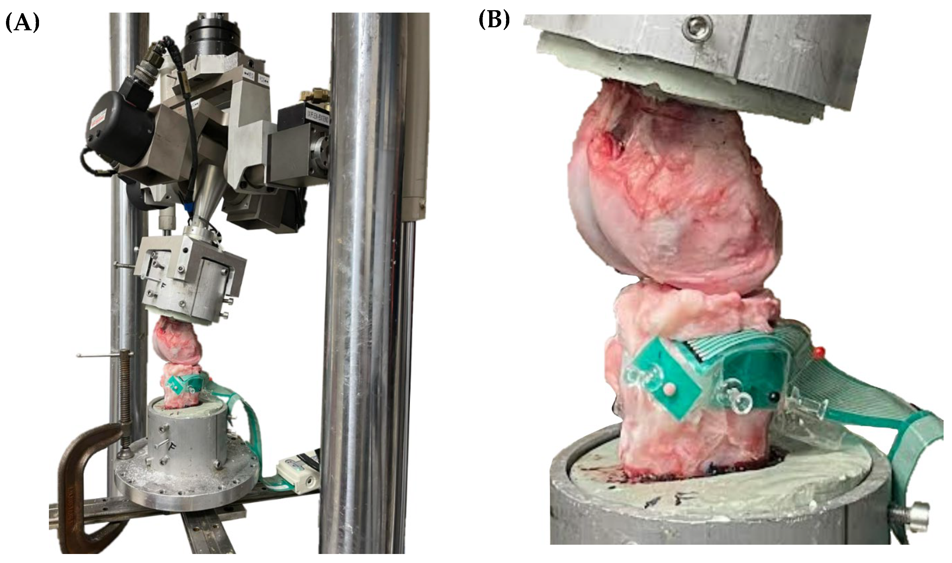
2.4. Compression Testing in Ex Vivo Porcine Knees

2.4.1. Porcine Knee Dissection

Porcine knee specimens were acquired from a commercial vendor (Animal Biotech Industries Inc., Doylestown, PA, USA). Excess muscle and soft tissue were dissected from approximately 10 cm of the distal femur and proximal tibia while keeping the joint capsule intact. The femur and tibia were both cleaned down to the bone to ensure optimal attachment to the potting resin. Additionally, the fibula was removed to simplify the potting process.

2.4.2. Porcine Knee Potting

The femur and tibia were both potted in cylindrical molds using Bondo resin for mounting on the MTS 858 Mini Bionix machine (MTS, Minneapolis, MN, USA). A bar clamp was used to position the femur and tibia over pre-cut PVC pipes measuring approximately 100 mm in diameter and 50 mm in height. The PVC pipe molds were fitted with parafilm over the bottom and sealed with painter’s tape to prevent leaks. Vaseline was applied to the inside of the mold to ensure release after the Bondo was cured.
The femur and tibia potting material was prepared by mixing equal parts of filler putty and resin (Bondo, 3M, St. Paul, MN, USA) for a total volume of 500 mL. Approximately 5 mL of blue-colored hardener was added and mixed until the color was uniform throughout. Then, 10 drops of liquid accelerator were added and mixed thoroughly. The mixture was then poured into the PVC mold with the tibia positioned in the middle. The tibia was positioned deep enough within the mold to cover several centimeters of the exposed bone. The mold was cured for 30 min, and the surrounding PVC pipe was removed. The tibia encased in Bondo was repositioned and secured to the bar clamp to allow the femur to hang down. The intact knee joint was placed in full extension using rubber bands, and the femur was positioned to be potted. The potting Bondo was poured again, covering the femur centered within the mold by several centimeters.

2.4.3. MTS Calibration

The potted porcine knee was secured in the MTS mini Bionix machine (Figure 3). The tibia was secured to a stationary platform, while the femur was secured in a gimbal with six degrees of freedom. The porcine knee was again placed in full extension and the gimbal angle measurements were recorded for calibration, as there are offset angles in the knee even at full extension. The X-flexion (X-flex) and valgus displacement (Z-lat) measurements were verified with X-ray measurements of the porcine knee (Figure 3B). Calibration ensured that all subsequent testing used a consistent alignment and that proper alignment was maintained after disarticulation.

2.4.4. Porcine Knee Disarticulation

After calibration, the porcine knee was disarticulated to allow for Tekscan sensor placement and access for suture repair. First, a scalpel was used to transect the patellar and quadriceps tendons to remove the patella. Next, the medial collateral ligament (MCL) and lateral collateral ligament (LCL) were transected at their attachment points. The porcine knee was placed in flexion and the anterior cruciate ligament (ACL) and posterior cruciate ligament (PCL) were transected to complete the disarticulation. The result was a tibia with intact menisci held in place by their anterior and posterior roots, along with some preserved joint capsule and a cleaned femoral head.

2.4.5. Tekscan Sensor Placement

The Tekscan Pressure Mapping Sensor 4011 (Tekscan, Norwood, MA, USA) was used to measure contact pressure applied to the meniscus and to generate a spatial heatmap of the force data. The sensor was oriented under the lateral meniscus with the curved side placed medially to provide better coverage of the meniscus without disrupting the anterior and posterior horns (Figure 4). The sensor was sealed with Tegaderm for waterproofing and secured using push pins. Due to the partially concave surface of the lateral tibial plateau, the sensor was not able to lie completely flat against the bone. This resulted in a small portion of the sensor floating over the bone surface. Small adjustments to the sensor positioning were made to minimize this floating space.

2.4.6. Porcine Meniscus Compression Testing

The disarticulated porcine knee, with the Tekscan sensor in place under the lateral meniscus, was secured in the MTS machine (Figure 4). The MTS machine was calibrated using the X-flex and Z-lat measurements obtained in Section 2.4.3 to ensure proper alignment during compression. The knee was then compressed at a rate of 2 N/s up to a maximum compression of 160 N. All subsequent testing used these same compression parameters.
After control testing, both the tibia and femur remained in their respective mounts, and the femur was raised vertically out of the working area. Then, using a surgical marker, the meniscectomy border was marked 3 mm from the outer border and spanning 1.5 cm of tissue centered around the lateral body of the meniscus. The border was then tapered internally in order to preserve the anterior and posterior horns. A small plastic sheet was inserted under the meniscus to protect the sensor while cutting the meniscectomy and suturing the repair. This allowed for the sensor to remain in place for all trails, ensuring spatial consistency in the heatmap data. Hemostats were used to grasp the superior border of the meniscus to elevate it above the plastic sheet. The meniscectomy was then cut using a scalpel. After removing the plastic sheet, the femur was lowered back into position, and the meniscus was compressed.
The femur was raised again out of the working area, and the protective plastic sheet was reinserted under the meniscus. 3D-printed meniscus implant fitting, suture marking, and 2/0 Fiberwire suturing were performed as described in Section 2.3.2. The plastic sheet was then removed, the femur was lowered back into position, and the meniscus was compressed again.

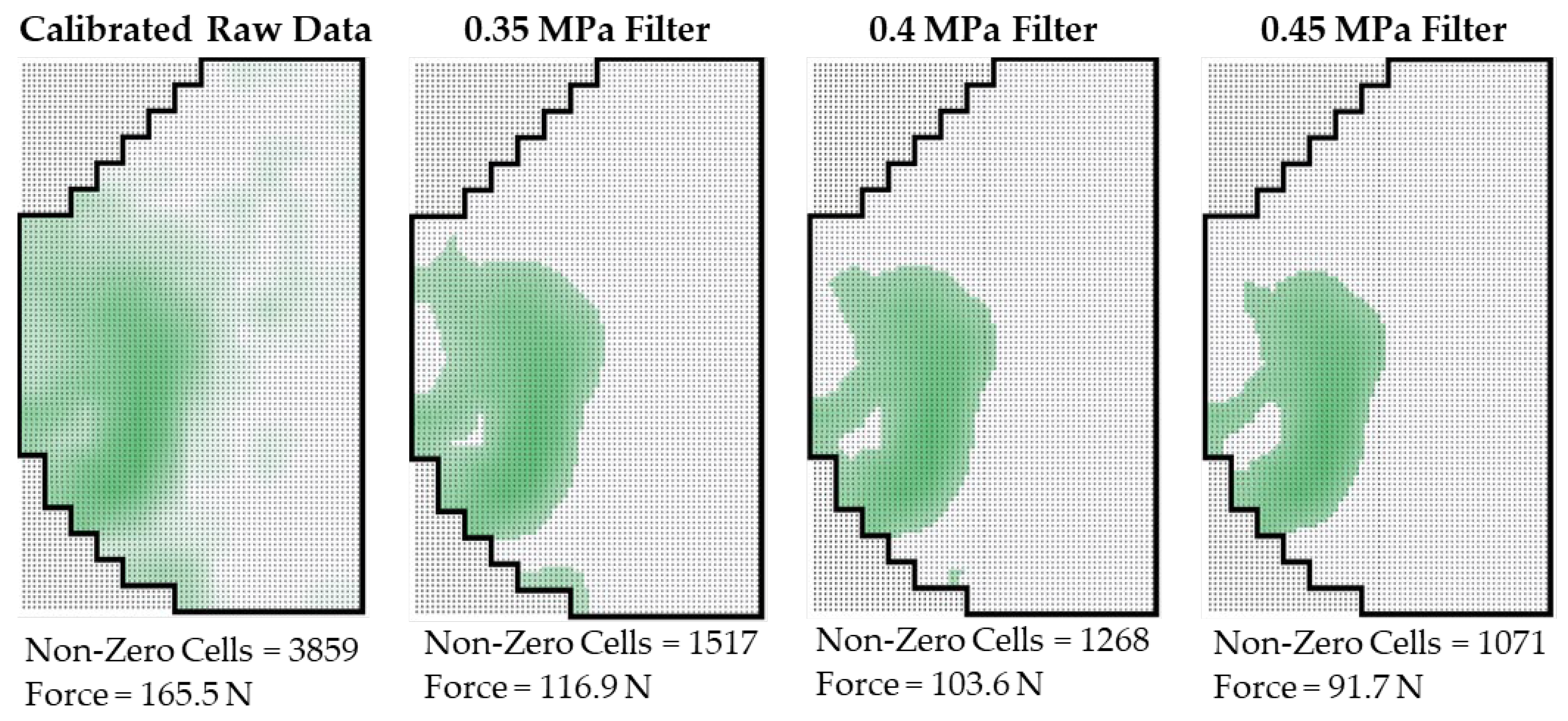
2.4.7. Tekscan Data Calibration

The Tekscan Pressure Mapping Sensor 4011 has 229 pressure reading cells with an individual cell area of 3.632   m m 2 / c e l l . Initially, each reading cell outputs a value from 0–128. This value is then converted to pressure once the sensor has been calibrated. Calibration occurs by attaching a probe to the MTS 858 Mini Bionix machine and then compressing down against the sensor at 160 N. The Tekscan software (K-Scan Research v7.70) uses this calibration test to reassign pressure values to all the reading cells, as seen in the heatmap images. The data output from testing was recorded at a higher resolution (5725 cells) using interpolation performed by the Tekscan reading software (K-Scan Research v7.70). The area per cell at the high-resolution setting was calculated as 0.145 mm2.
A validation calculation was performed in Excel on the raw data from the intact meniscus control heat map to determine if the sensor was calibrated correctly. All raw values were summed and converted from pressure (MPa) to force (N) by multiplying by the cell area. The summed force was 165.5 N for the 160 N compression setting of the MTS machine, which is a 3.4% error.

3. Results

3.1. 3D-Printed Meniscus Fabrication

We printed 25 menisci for use in testing and protocol formation. In Table 1, we show the physical dimensions of the four menisci selected for final testing. These prints were selected based on their consistency in the amount of extruded ink and overall dimensions to ensure continuity between tests. Menisci #1 and #2 were used in the final 2/0 Fiberwire pull-out testing. Meniscus #3 was used in the final isolated porcine meniscus compression, and meniscus #4 was used in the final ex vivo porcine knees compression. Most of the other 3D-printed menisci were used in protocol development and practice trials.
The extrusion pressure was varied for each print based on small corrections from previous prints. For example, if a meniscus with an extrusion pressure of 50 kPa resulted in a meniscus with smaller dimensions, the next meniscus would be printed at a slightly higher pressure setting. The volume was determined from the change in the volume of ink remaining in the syringe before and after the print. The X- and Y-dimensions were measured as shown in Figure 5. The Z-dimension, or height, was measured with calipers. The R-average was calculated by averaging the radial thickness in the three locations shown.

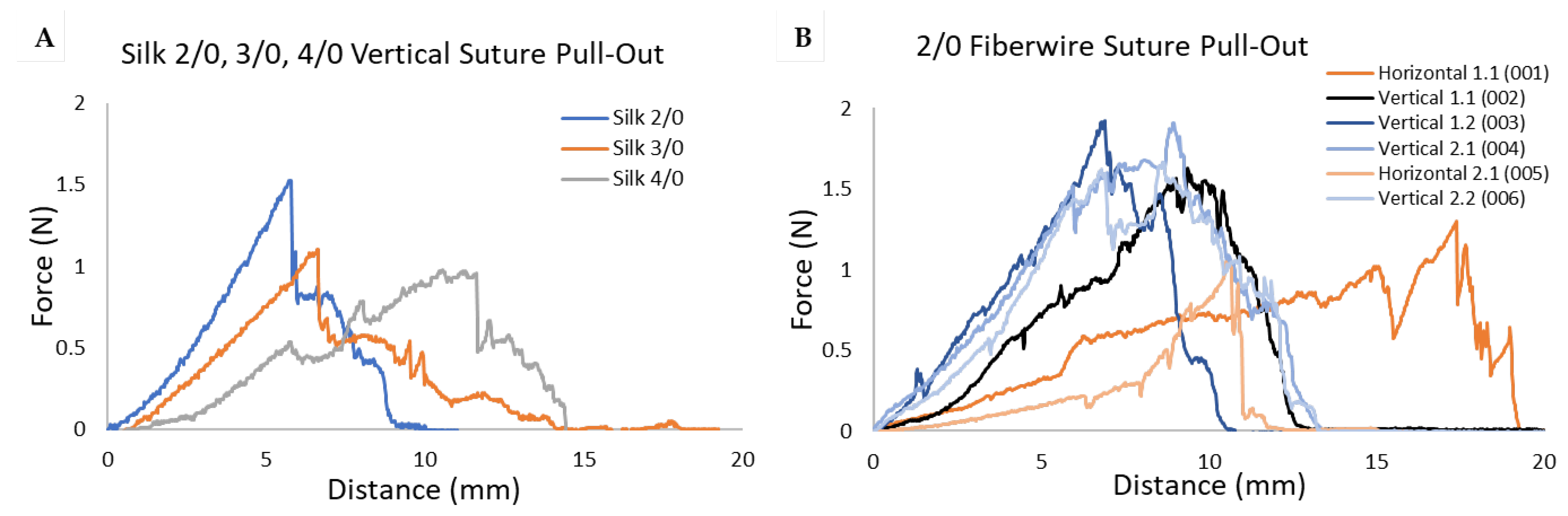
3.2. Suture Pull-Out Force

Initial suture pull-out testing was performed by placing simple vertical interrupted sutures for silk, nylon, polypropylene (PP), and polyethylene (PE) suture types in the 3D-printed meniscus to determine if the meniscus could hold sutures and if the suture material and sizing was important. Each suture type was tested at the 2/0, 3/0, and 4/0 sizes and pulled out at a rate of 0.1 mm/s. The silk suture is shown as an example in Figure 6A. As the tension sensor pulls the suture upward, the suture pulls through the meniscus, and a corresponding increase in force is detected by the load cell. The rapid drop in force at 6 mm for the 2/0 silk indicates that the suture had partially torn through the 3D-printed meniscus. The 2/0 silk suture continued to tear gradually through the remaining meniscus until it completely pulled out at around 9 mm. The data is summarized in Figure 7A and show that forces ranging from 0.5–1.6 N were measured prior to 3D-printed meniscal failure and complete suture pull-through. Higher forces were required to pull out the 2/0 sutures compared with those needed for the 3/0 and 4/0 sutures.
After the preliminary data showed that vertical sutures of varying material and sizes could be held by the 3D-printed meniscus, 2/0 silk was chosen for additional replicate testing. We also tested Fiberwire, as it is commonly used by orthopedic surgeons during meniscal repair [38]. Menisci #1 and #2 were used to collect two horizontal and four vertical Fiberwire suture pull-out force measurements. Both horizontal and vertical sutures were placed in each sample, and the placement of the horizontal suture was shifted from lateral to midline between the samples to avoid any confounding of the spatial orientation (Figure 8). Each suture was placed and pulled out sequentially at a rate of 0.1 mm/s. There was no interference by the torn meniscus at the insertion site of the next suture, allowing all tests to be perform in regionally intact menisci. Fiberwire Trial 002 showed a progressive tensile force building as the suture was slowly pulled through the 3D-printed meniscus, with a sharp decrease occurring once a force of 1.8 N was measured (Figure 6B). This corresponded to the suture tearing through the meniscus. The force recorded for trials 003, 004, and 006 showed graphs with two distinct peaks before a sharp decrease, indicating a partial tear-through in the printed meniscus with the first peak and a complete tear-through occurring beyond the second peak (Figure 6B). For the silk and Fiberwire pull-out data (Figure 7B,C), we compared groups using an unpaired t-test. Vertical silk or Fiberwire sutures required more force to tear through the 3D-printed meniscus than horizontal sutures (p < 0.01), and Fiberwire sutures withstood greater force than silk (p < 0.05).

3.3. Compression Testing in Isolated Porcine Menisci

Four isolated lateral porcine menisci were selected based on their similar dimensions to the 3D-printed meniscus and used to evaluate repair with the 3D-printed meniscus. The menisci following meniscectomy, suture repair, and suturing with tissue-glue repair were subsequently compressed to a 25% strain (Figure 9). Each sample shown was compressed at a rate of 0.1 N/s, and force vs. strain curves were generated (Figure 9F) and used to compare each sample. The control menisci exhibited an average force of 26.7 ± 0.85 N when compressed to 25% of the original height (0.25 strain on the X axis). The average maximum compressive force measured on menisci with meniscectomy (orange) dropped to 7.43 ± 0.81 N, demonstrating that the meniscectomy weakened the meniscus by 72% at 25% strain. The suture-repaired (grey) and the combined suture-and-tissue-glue-repaired meniscus (yellow) brought the average maximum compressive force to 15.5 ± 2.2 N and 17.8 ± 2.2 N, respectively. Thus, the combined suture-and-tissue-glue-repaired meniscus was able to strengthen the meniscectomy meniscus and restore stiffness to approximately 66% of the intact control compressive-force strength.

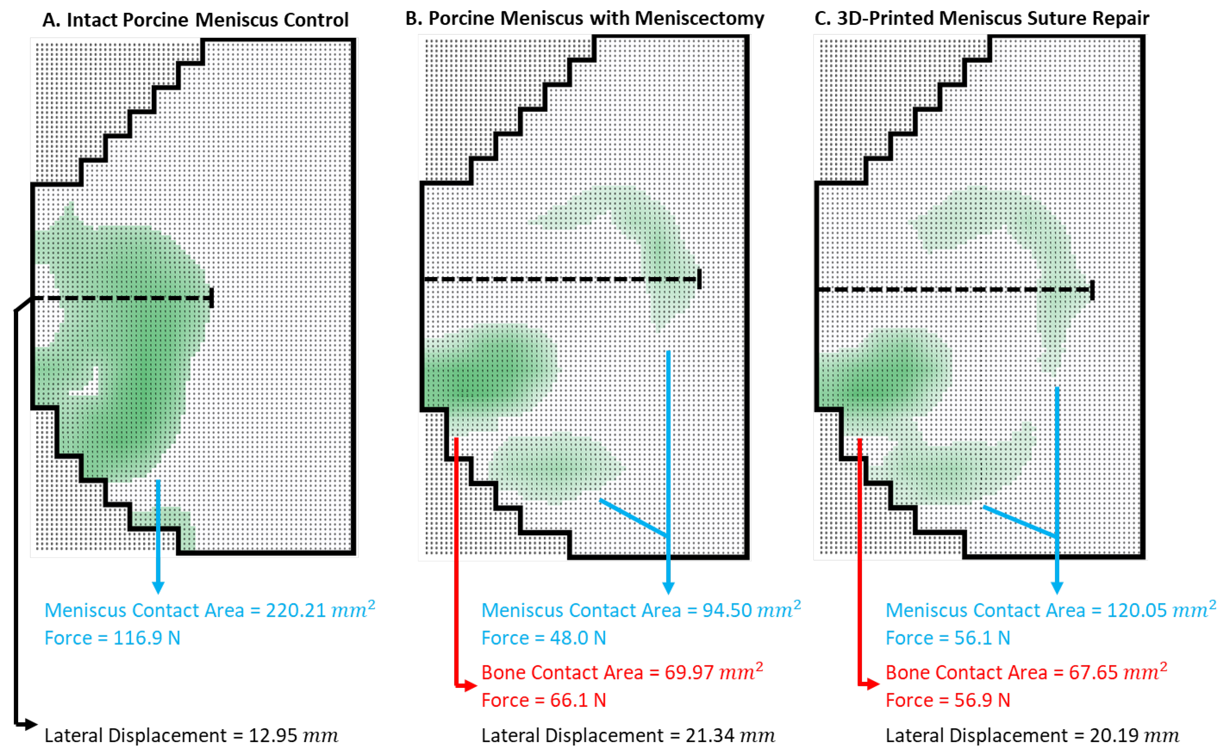
3.4. Compression Testing in Ex Vivo Porcine Knees

As the last step in the meniscal repair device testing, we evaluated how knee biomechanics are affected by meniscal damage and repair using an MTS mechanical tester. This test is extremely important, and the setup is quite a detailed process. We tested an intact porcine meniscus control, a porcine meniscus with meniscectomy, and repair with 3D-printed meniscal tissue. Compression testing was performed sequentially in the same porcine knee. It is important to perform sequential testing within the same knee to account for variations in joint size, tibial-plateau surface shape, and Tekscan sensor placement. A maximum compression force of 160 N was applied by the MTS machine for all tests. Anatomic views of the specimens before compression and their corresponding heatmaps after compression are shown in Figure 10. The control meniscus can be seen as the light-blue crescent in the heatmap of pressure data (Figure 10A). The meniscectomy resulted in lateral displacement of the meniscus as well as a significant nascent femur–tibia bone contact, indicated by the red coloring in the corresponding heat map (Figure 10B). The meniscal repair made with the 3D-printed meniscus relieved some of the bone contact as evidenced by the lighter coloring (Figure 10C).
The calibrated raw data was filtered to reduce noise and to determine the amount of force applied to the meniscus. Filters of 0.35 mPa, 0.4 MPa, and 0.45 MPa were applied (Figure 11). It was determined that a filter of 0.35 MPa was appropriate, as it excluded noise data from the periphery of the Tekscan sensor that was outside the joint space while minimizing data exclusion in the region of the meniscus. The 0.35 MPa filter was used for all data sets.
A compressive force of 116.9 N was measured for the intact porcine meniscus control (Figure 12A). Because the meniscectomy resulted in two areas of contact, the meniscus and a new bone-contact area, the force was computed separately for these two regions. In this example, meniscus contact forces dropped to 48.0 N following meniscectomy, which weakened the knee joint by 60%. The resulting bone-contact force was 66.1 N (Figure 12B). The sum of the forces measured and filtered in the two contact areas was 114 N, which was similar to that of the intact control sample.
Using the 3D-printed meniscus to repair the meniscectomy resulted in a measured compressive force of 56.1 N (Figure 12C). The suture repair strengthened the meniscus by 17% and was able to restore 48% of the intact control compressive-force strength. The bone-contact force, outlined in red, was 56.9 N. The repair relieved 14% of the compressive stress from bone contact in this data set. The total force measured was 113 N, which was again similar to that of the control knee. These data illustrate the quantitative analysis possible with this testing methodology. A complete assessment would require compiling these results across sufficient replicates to produce statistically significant comparisons. In this example, the 3D-printed meniscus failed to restore normal knee contact pressure. Detecting sub-optimal performance of a novel meniscal repair device at this stage in development is advantageous in that it allows the researcher an opportunity for device improvement prior to moving on to expensive live-animal studies.
Meniscal extrusion was observed in the pressure-mapping data sets. Extrusion is the lateral displacement of meniscal tissue when the knee is loaded and is commonly measured starting at fixed points such as the lateral border of the PCL and extending to the outermost border of the meniscus [42]. Since the PCL had been dissected away during knee disarticulation, relative extrusion was calculated by setting the reference point at the outermost border of the meniscus during intact control testing. Since the sensor remained in place for all subsequent testing, extrusion distances were calculated using the medial border of the sensor as a reference point. Therefore, the measurement from the medial border of the sensor to the outermost border of the lateral meniscus in the control test, meniscectomy, and repair were 12.95 mm, 21.34 mm, and 20.19 mm respectively (Figure 12A–C). The meniscectomy meniscus had 8.39 mm of meniscal extrusion. The repaired meniscus had 7.24 mm of meniscal extrusion and improved meniscus centralization by 1.15 mm.

4. Discussion

The paper illustrates the steps needed to evaluate the effectiveness of novel meniscus repair devices. For successful meniscal repair, the devices must hold up under fixation methods such as suturing, must recapture close to native-like stiffness, and must restore knee contact areas, pressure, and biomechanics. To demonstrate these evaluations, we used a 3D-printed meniscus composed of native-like collagen and chondroitin.
As the first step in bridging the gap between laboratory research and surgical relevance, we showed that the 3D-printed meniscus was able to hold sutures of various types, sizes, and orientations (Figure 6 and Figure 7). Also, a reliable method and novel testing apparatus was developed to perform suture pull-out experiments. It was unknown how the 3D-printed meniscus would react to the physical damage caused by needle penetration, suture friction, and tension during tying. In previous studies, the suture needle-puncture force had been shown to decrease with increasing insertion velocity, round cross-section, and orthogonal insertion [43]. The 2/0 Fiberwire used a 3/8c T-13 taper needle with a round cross-section and was a likely optimal choice for 3D-printed meniscus protection during needle insertion. Friction at the suture–tissue interface had also been shown to increase with braided versus monofilament sutures and as the suture size increased [33]. Although braided versus monofilament differences were not readily seen in the limited trials performed in this study, the effect of size can be clearly seen across all materials.
There were marked differences in the maximum pull-out force between vertical and horizontal sutures. The interrupted vertical sutures consistently required more pull-out force to drag and rip through the 3D-printed meniscus compared with horizontal sutures in the 2/0 silk trials (Figure 7B). The 2/0 Fiberwire trials showed that 44% more force was required to pull out vertical sutures compared with horizontal sutures (Figure 7C). This difference is likely due to the internal architecture of the 3D-printed meniscus, which includes many more circumferential extrusions than radial extrusions. Placing an uninterrupted suture perpendicular to the circumferential layers is likely to have more resistance to the pull-out force. However, the average maximum pull-out force of 1.78 N through the 3D-printed meniscus falls well short of the maximum pull-out force reported from several other studies using native meniscus tissue. We were unable to quantify the suture pull-out force in the porcine meniscal tissue because the load-cell maximum was reached before tear-through. Boenisch et al. showed that the vertical suture pull-out force was 72.4 N in age-matched bovine menisci, which was comparable to the 67 N in human cadaveric samples found by Rimmer et al. [30,32]. Feucht et al. found that the pull-out force in a lateral porcine meniscus using 2/0 Fiberwire was as high as 169.0 N [31]. This study was the most similar to our study design as it used the same tissue and suture type. Additional tests may be applicable for meniscal repair device testing, such as cyclic suture loading [44]. While the 3D-printed meniscus did not provide as strong a resistance to suture pull-out as native tissue did, it was able to tolerate suturing and knot tying with 2/0 Fiberwire.
Many of the suture pull-out force graphs had two distinct peaks. This indicates a partial tear-through followed by the suture catching onto material and building the pull-out force again until the final tear-through. This is likely due to the internal architecture of the 3D-printed meniscus, which is made of multiple extruded lines instead of being a homogeneous material. The inner extrusions may be weaker than the surface layers due to less penetration of UV light for crosslinking. Further work is required to fully explain this phenomenon.
We showed that the 3D-printed meniscus can be cut and surgically implanted to repair meniscectomies to partially restore compressive strength. The surgical technique for the 3D-printed meniscus implant used in this study was adapted from a collagen meniscus implant (CMI) that has been well established in the literature. The CMI was surgically implanted into defects extending into the red–red zone with between two to six non-absorbable 2/0 sutures using an inside-out technique [45]. Similar parameters were used for the 3D-printed meniscus surgical implantation in this study. Additionally, the testing showed promising restoration of the meniscal compressive strength after repair (Figure 9). To the best of our knowledge, use of a simple uniaxial compression tester to evaluate the efficacy of meniscal repair has not been demonstrated; however, we believe that this method can provide valuable insight into the effectiveness of meniscal repair in a simpler and more budget-friendly system compared with the ex vivo knee biomechanics testing.
In an ex vivo porcine knee joint, repair after meniscectomy with the 3D-printed meniscus resulted in slight restoration of knee-joint forces. The use of Tekscan pressure sensors was critical for assessing tibiofemoral contact pressures. The low thickness and continuous measurement are major advantages, but numerous factors make pressure mapping challenging. Herregodts et al. describe wrinkling of the sensor, uneven test surfaces, and the lack of reliable fixation methods as contributing large effects on the accuracy of the sensor [46]. All three of these factors were experienced while using Tekscan sensors in this study, though care was taken to minimize the effects of these factors.
Several previous studies show that partial meniscectomy leads to a decreased contact area and increased contact pressures. Koh et al. studied inferior and superior leaf meniscectomies in the repair of horizontal cleavage tears in the medial meniscus. Their study showed that meniscectomy reduced the contact area to approximately 60%, with a corresponding 180% increase in peak contact pressures [35]. Ode et al. showed similar trends when studying radial tears in the medial meniscus [36]. Kubota et al. studied the effect of a centralization procedure to restore the hoop strain in an extruded lateral meniscus. Meniscal extrusion is the lateral displacement of the meniscus under load that is caused by the hoop-stress dysfunction commonly seen after meniscectomy. It was measured from the fixed reference point of the lateral edge of the PCL to the outermost border of the lateral meniscus. They found that the meniscectomy meniscus extruded approximately 6 mm at 30 degrees of flexion under a 200 N load compared with the intact control [42]. Extrusion values in our study were slightly greater, which is likely due to the larger meniscectomy performed. It is possible that the degree of extrusion may be influenced by the disarticulation of the joint used here. Meniscal extrusion is closely related to the progression of osteoarthritis [47,48]. In a clinical study, Kim et al. studied long-term patient outcomes after common meniscal-tear treatments, partial meniscectomies, and subtotal meniscectomy. At 5 years of follow up, joint-space narrowing was seen in all categories of repair. Partial meniscectomies and subtotal meniscectomies showed a 10% and 24% reduction in joint space, respectively [49]. Joint-space narrowing is closely associated with osteoarthritis from articular cartilage degradation.
Though our data indicated that the 3D-printed meniscus needs to be made stiffer in order to better repair the meniscectomy in a porcine knee joint, the methods presented here represent a good template to guide others when assessing novel tissue-engineered meniscal implants. We feel that whole-knee-joint pressure mapping is a critical testing step prior to the initiation of any live-animal work. While the data presented will help further our 3D-printed meniscus device, this work also established comprehensive methods for testing meniscal repair. We suggest that different flexion angles and loading forces be tested in the ex vivo knee experiments. We also strongly suggest that each test be repeated enough times to generate statistically significant results. The experiments presented here in our compression testing, both in the isolated porcine meniscus and the ex vivo knee, serve to validate the value of the methods.
The data presented here suggest that the 3D-printed meniscus would likely have failed in a small- or large-mammal model. Thus, our next steps will be to strengthen the 3D-printed meniscus. For example, the ink composition and concentration can be changed, and materials such as thermoplastics may be used to provide internal stiffening or suture-fastening points. The inclusion of cells in the ink (bioprinting) coupled with cyclical compression may lead to structural remodeling and stiffening of the collagen-based materials [50,51,52,53].

5. Conclusions

The methods described in this work serve as a guide for the evaluation of novel meniscus repair devices and methods. In our example, a 3D-printed meniscus composed of a collagen-based ink was capable of holding sutures and repairing defects created in an isolated porcine meniscus. The uniaxial compression-testing data was promising and indicated that the repaired meniscus was 66% as strong as the undamaged meniscus. However, when contact pressure and area were evaluated in the more complex setting of a whole porcine knee joint, the 3D-printed meniscus was unable to restore near-normal contact pressures. The data values reported in these tests are for illustrative purposes. These results demonstrate that a combination of several testing methods should be applied to novel meniscus repair devices in order to evaluate their ability to functionally repair a damaged meniscus prior to moving into pre-clinical testing with live animals. Though we have presented several ways to evaluate meniscal repair in vitro, this paper does not cover all possible methods such as more detailed knee kinematics or animal studies. We recommend that several repetitions of each test be performed to generate statistically significant data sets.

Author Contributions

Conceptualization, A.N., G.J.K. and V.B.H.; methodology, A.N., S.V. and G.J.K.; software, A.N. and S.V.; validation, A.N.; formal analysis, A.N., S.V., K.H.G. and G.J.K.; investigation, A.N., J.T., S.V. and G.J.K.; resources, M.H. and V.B.H.; data curation, A.N.; writing—A.N. and G.J.K.; writing—review and editing, A.N., K.H.G., S.V., V.B.H. and G.J.K.; visualization, A.N.; supervision, G.J.K. and K.H.G.; project administration, K.H.G., G.J.K. and V.B.H.; funding acquisition, V.B.H. All authors have read and agreed to the published version of the manuscript.

Funding

This research was funded by Grant # HU00011920022 from the Uniformed Services University of the Health Sciences and is administered by The Geneva Foundation, 950 Broadway, Suite 307, Tacoma, WA 98402. The opinions and assertions expressed herein are those of the authors and do not necessarily reflect the official policy or position of the Uniformed Services University of the Health Sciences, Walter Reed National Military Medical Center or the Department of Defense.

Institutional Review Board Statement

Not applicable.

Informed Consent Statement

Not applicable.

Data Availability Statement

The raw data supporting the conclusions of this article will be made available by the authors on request.

Conflicts of Interest

The authors declare no conflicts of interest.

References

  1. Athanasiou, K.A.; Sanchez-Adams, J. Engineering the Knee Meniscus; Morgan and Claypool: San Rafael, CA, USA, 2009. [Google Scholar]
  2. Logerstedt, D.S.; Snyder-Mackler, L.; Ritter, R.C.; Axe, M.J.; Orthopedic, A. Section of the American Physical Therapy, Knee pain and mobility impairments: Meniscal and articular cartilage lesions. J. Orthop. Sports Phys. Ther. 2010, 40, A1–A35. [Google Scholar] [PubMed]
  3. Nielsen, A.B.; Yde, J. Epidemiology of acute knee injuries: A prospective hospital investigation. J. Trauma 1991, 31, 1644–1648. [Google Scholar] [CrossRef] [PubMed]
  4. Donohue, M.A.; Zhou, L.; Haley, C.A. Meniscus Injuries in the Military Athlete. J. Knee Surg. 2019, 32, 123–126. [Google Scholar] [PubMed]
  5. Jones, J.C.; Burks, R.; Owens, B.D.; Sturdivant, R.X.; Svoboda, S.J.; Cameron, K.L. Incidence and risk factors associated with meniscal injuries among active-duty US military service members. J. Athl. Train. 2012, 47, 67–73. [Google Scholar] [CrossRef] [PubMed]
  6. Snoeker, B.A.; Bakker, E.W.; Kegel, C.A.; Lucas, C. Risk factors for meniscal tears: A systematic review including meta-analysis. J. Orthop. Sports Phys. Ther. 2013, 43, 352–367. [Google Scholar] [CrossRef]
  7. Cook, J.L. The current status of treatment for large meniscal defects. Clin. Orthop. Relat. Res. 2005, 435, 88–95. [Google Scholar] [CrossRef]
  8. Doral, M.N.; Bilge, O.; Huri, G.; Turhan, E.; Verdonk, R. Modern treatment of meniscal tears. EFORT Open Rev. 2018, 3, 260–268. [Google Scholar] [CrossRef]
  9. Antosh, I.J.; Cameron, K.L.; Marsh, N.A.; Posner, M.A.; DeBerardino, T.M.; Svoboda, S.J.; Owens, B.D. Likelihood of Return to Duty Is Low After Meniscal Allograft Transplantation in an Active-duty Military Population. Clin. Orthop. Relat. Res. 2020, 478, 722–730. [Google Scholar] [CrossRef]
  10. Lee, J.M.; Yeong, W.Y. Design and Printing Strategies in 3D Bioprinting of Cell-Hydrogels: A Review. Adv. Healthc. Mater. 2016, 5, 2856–2865. [Google Scholar] [CrossRef]
  11. Yan, Q.; Dong, H.; Su, J.; Han, J.; Song, B.; Wei, Q.; Shi, Y. A Review of 3D Printing Technology for Medical Applications. Engineering 2018, 4, 729–742. [Google Scholar] [CrossRef]
  12. Chartrain, N.A.; Gilchrist, K.H.; Ho, V.B.; Klarmann, G.J. 3D bioprinting for the repair of articular cartilage and osteochondral tissue. Bioprinting 2022, 28, e00239. [Google Scholar] [CrossRef]
  13. Senior, J.J.; Cooke, M.E.; Grover, L.M.; Smith, A.M. Fabrication of Complex Hydrogel Structures Using Suspended Layer Additive Manufacturing (SLAM). Adv. Funct. Mater. 2019, 29, 1904845. [Google Scholar] [CrossRef]
  14. Moxon, S.R.; Cooke, M.E.; Cox, S.C.; Snow, M.; Jeys, L.; Jones, S.W.; Smith, A.M.; Grover, L.M. Suspended Manufacture of Biological Structures. Adv. Mater. 2017, 29, 1605594. [Google Scholar] [CrossRef] [PubMed]
  15. Hinton, T.J.; Jallerat, Q.; Palchesko, R.N.; Park, J.H.; Grodzicki, M.S.; Shue, H.J.; Ramadan, M.H.; Hudson, A.R.; Feinberg, A.W. Three-dimensional printing of complex biological structures by freeform reversible embedding of suspended hydrogels. Sci. Adv. 2015, 1, e1500758. [Google Scholar] [CrossRef] [PubMed]
  16. Bahcecioglu, G.; Hasirci, N.; Bilgen, B.; Hasirci, V. A 3D printed PCL/hydrogel construct with zone-specific biochemical composition mimicking that of the meniscus. Biofabrication 2019, 11, 025002. [Google Scholar] [CrossRef] [PubMed]
  17. Narayanan, L.K.; Huebner, P.; Fisher, M.B.; Spang, J.T.; Starly, B.; Shirwaiker, R.A. 3D-Bioprinting of Polylactic Acid (PLA) Nanofiber-Alginate Hydrogel Bioink Containing Human Adipose-Derived Stem Cells. ACS Biomater. Sci. Eng. 2016, 2, 1732–1742. [Google Scholar] [CrossRef] [PubMed]
  18. Zhang, Z.Z.; Wang, S.J.; Zhang, J.Y.; Jiang, W.B.; Huang, A.B.; Qi, Y.S.; Ding, J.X.; Chen, X.S.; Jiang, D.; Yu, J.K. 3D-Printed Poly(epsilon-caprolactone) Scaffold Augmented with Mesenchymal Stem Cells for Total Meniscal Substitution: A 12- and 24-Week Animal Study in a Rabbit Model. Am. J. Sports Med. 2017, 45, 1497–1511. [Google Scholar] [CrossRef]
  19. Bahcecioglu, G.; Bilgen, B.; Hasirci, N.; Hasirci, V. Anatomical meniscus construct with zone specific biochemical composition and structural organization. Biomaterials 2019, 218, 119361. [Google Scholar] [CrossRef]
  20. Szojka, A.; Lalh, K.; Andrews, S.H.J.; Jomha, N.M.; Osswald, M.; Adesida, A.B. Biomimetic 3D printed scaffolds for meniscus tissue engineering. Bioprinting 2017, 8, 1–7. [Google Scholar] [CrossRef]
  21. ICengiz, F.; Pitikakis, M.; Cesario, L.; Parascandolo, P.; Vosilla, L.; Viano, G.; Oliveira, J.M.; Reis, R.L. Building the basis for patient-specific meniscal scaffolds: From human knee MRI to fabrication of 3D printed scaffolds. Bioprinting 2016, 1–2, 1–10. [Google Scholar] [CrossRef]
  22. Romanazzo, S.; Vedicherla, S.; Moran, C.; Kelly, D.J. Meniscus ECM-functionalised hydrogels containing infrapatellar fat pad-derived stem cells for bioprinting of regionally defined meniscal tissue. J. Tissue Eng. Regen. Med. 2018, 12, e1826–e1835. [Google Scholar] [CrossRef] [PubMed]
  23. Bandyopadhyay, A.; Mandal, B.B. A three-dimensional printed silk-based biomimetic tri-layered meniscus for potential patient-specific implantation. Biofabrication 2019, 12, 015003. [Google Scholar] [CrossRef] [PubMed]
  24. Zhang, Z.Z.; Chen, Y.R.; Wang, S.J.; Zhao, F.; Wang, X.G.; Yang, F.; Shi, J.J.; Ge, Z.G.; Ding, W.Y.; Yang, Y.C.; et al. Orchestrated biomechanical, structural, and biochemical stimuli for engineering anisotropic meniscus. Sci. Transl. Med. 2019, 11, eaao0750. [Google Scholar] [CrossRef] [PubMed]
  25. Klarmann, G.J.; Piroli, M.E.; Loverde, J.R.; Nelson, A.F.; Li, Z.; Gilchrist, K.H.; Gaston, J.D.; Ho, V.B. 3D printing a universal knee meniscus using a custom collagen ink. Bioprinting 2023, 31, e00272. [Google Scholar] [CrossRef]
  26. Puetzer, J.L.; Bonassar, L.J. High density type I collagen gels for tissue engineering of whole menisci. Acta Biomater. 2013, 9, 7787–7795. [Google Scholar] [CrossRef]
  27. Klarmann, G.J.; Gaston, J.; Ho, V.B. A review of strategies for development of tissue engineered meniscal implants. Biomater. Biosyst. 2021, 4, 100026. [Google Scholar] [CrossRef] [PubMed]
  28. Drakos, M.C.; Allen, A.A. Meniscal Structure, Function, Repair, and Replacement. In Oncology and Basic Science; Damron, T.A., Ed.; Lippincott Williams and Wilkins: Philadelphia, PA, USA, 2008; pp. 443–451. [Google Scholar]
  29. Skaggs, D.L.; Warden, W.H.; Mow, V.C. Radial tie fibers influence the tensile properties of the bovine medial meniscus. J. Orthop. Res. 1994, 12, 176–185. [Google Scholar] [CrossRef]
  30. Boenisch, U.W.; Faber, K.J.; Ciarelli, M.; Steadman, J.R.; Arnoczky, S.P. Pull-out strength and stiffness of meniscal repair using absorbable arrows or Ti-Cron vertical and horizontal loop sutures. Am. J. Sports Med. 1999, 27, 626–631. [Google Scholar] [CrossRef]
  31. Feucht, M.J.; Grande, E.; Brunhuber, J.; Rosenstiel, N.; Burgkart, R.; Imhoff, A.B.; Braun, S. Biomechanical evaluation of different suture materials for arthroscopic transtibial pull-out repair of posterior meniscus root tears. Knee Surg Sports Traumatol. Arthrosc. 2015, 23, 132–139. [Google Scholar] [CrossRef]
  32. Rimmer, M.G.; Nawana, N.S.; Keene, G.C.; Pearcy, M.J. Failure strengths of different meniscal suturing techniques. Arthroscopy 1995, 11, 146–150. [Google Scholar] [CrossRef]
  33. Zhang, L.; Li, W.; Lin, C.; Zhou, Z. Friction Behavior at the Interface Between Surgical Sutures and Tissues. Tribol. Lett. 2017, 65, 127. [Google Scholar] [CrossRef]
  34. Matthews, J.R.; Wang, J.; Zhao, J.; Kluczynski, M.A.; Bisson, L.J. The influence of suture materials on the biomechanical behavior of suture-meniscal specimens: A comparative study in a porcine model. Knee Surg. Relat. Res. 2020, 32, 42. [Google Scholar] [CrossRef] [PubMed]
  35. Koh, J.L.; Yi, S.J.; Ren, Y.; Zimmerman, T.A.; Zhang, L.-Q. Tibiofemoral Contact Mechanics with Horizontal Cleavage Tear and Resection of the Medial Meniscus in the Human Knee. J. Bone Jt. Surg. 2016, 98, 1829–1836. [Google Scholar] [CrossRef] [PubMed]
  36. Ode, G.E.; Van Thiel, G.S.; McArthur, S.A.; Dishkin-Paset, J.; Leurgans, S.E.; Shewman, E.F.; Wang, V.M.; Cole, B.J. Effects of serial sectioning and repair of radial tears in the lateral meniscus. Am. J. Sports Med. 2012, 40, 1863–1870. [Google Scholar] [CrossRef] [PubMed]
  37. Mazy, D.; Chung-Tze-Cheong, C.; Ma, Z.; Huo, R.; Lamer, S.; Li, J.; Nault, M.L. Tough gel adhesive is an effective method for meniscal repair in a bovine cadaveric study. J. Exp. Orthop. 2023, 10, 139. [Google Scholar] [CrossRef]
  38. Aros, B.C.; Pedroza, A.; Vasileff, W.K.; Litsky, A.S.; Flanigan, D.C. Mechanical comparison of meniscal repair devices with mattress suture devices in vitro. Knee Surg Sports Traumatol. Arthrosc. 2010, 18, 1594–1598. [Google Scholar] [CrossRef]
  39. Chia, H.N.; Hull, M.L. Compressive moduli of the human medial meniscus in the axial and radial directions at equilibrium and at a physiological strain rate. J. Orthop. Res. 2008, 26, 951–956. [Google Scholar] [CrossRef]
  40. Long, T.; Shende, S.; Lin, C.Y.; Vemaganti, K. Experiments and hyperelastic modeling of porcine meniscus show heterogeneity at high strains. Biomech. Model Mechanobiol. 2022, 21, 1641–1658. [Google Scholar] [CrossRef]
  41. Morejon, A.; Norberg, C.D.; De Rosa, M.; Best, T.M.; Jackson, A.R.; Travascio, F. Compressive Properties and Hydraulic Permeability of Human Meniscus: Relationships With Tissue Structure and Composition. Front. Bioeng. Biotechnol. 2020, 8, 622552. [Google Scholar] [CrossRef]
  42. Kubota, R.; Koga, H.; Ozeki, N.; Matsuda, J.; Kohno, Y.; Mizuno, M.; Katano, H.; Sekiya, I. The effect of a centralization procedure for extruded lateral meniscus on load distribution in porcine knee joints at different flexion angles. BMC Musculoskelet. Disord. 2020, 21, 205. [Google Scholar] [CrossRef]
  43. Bao, X.; Li, W.; Lu, M.; Zhou, Z.R. Experiment study on puncture force between MIS suture needle and soft tissue. Biosurface Biotribol. 2016, 2, 49–58. [Google Scholar] [CrossRef]
  44. Zantop, T.; Temmig, K.; Weimann, A.; Eggers, A.K.; Raschke, M.J.; Petersen, W. Elongation and structural properties of meniscal repair using suture techniques in distraction and shear force scenarios: Biomechanical evaluation using a cyclic loading protocol. Am. J. Sports Med. 2006, 34, 799–805. [Google Scholar] [CrossRef]
  45. Zaffagnini, S.; Giordano, G.; Vascellari, A.; Bruni, D.; Neri, M.P.; Iacono, F.; Kon, E.; Presti, M.L.; Marcacci, M. Arthroscopic collagen meniscus implant results at 6 to 8 years follow up. Knee Surg Sports Traumatol. Arthrosc. 2007, 15, 175–183. [Google Scholar] [CrossRef]
  46. Herregodts, S.; Baets, P.D.; Victor, J.; Verstraete, M.A. Use of Tekscan pressure sensors for measuring contact pressures in the human knee joint. Int. J. Sustain. Constr. Des. 2015, 6, 7. [Google Scholar] [CrossRef]
  47. Sharma, L.; Chmiel, J.S.; Almagor, O.; Dunlop, D.; Guermazi, A.; Bathon, J.M.; Eaton, C.B.; Hochberg, M.C.; Jackson, R.D.; Kwoh, C.K.; et al. Significance of preradiographic magnetic resonance imaging lesions in persons at increased risk of knee osteoarthritis. Arthritis Rheumatol. 2014, 66, 1811–1819. [Google Scholar] [CrossRef] [PubMed]
  48. Willinger, L.; Foehr, P.; Achtnich, A.; Forkel, P.; Voss, A.; Liska, F.; Lacheta, L.; Imhoff, A.B.; Burgkart, R. Effect of Lower Limb Alignment in Medial Meniscus-Deficient Knees on Tibiofemoral Contact Pressure. Orthop. J. Sports Med. 2019, 7, 2325967118824611. [Google Scholar] [CrossRef] [PubMed]
  49. Kim, S.J.; Lee, S.K.; Kim, S.H.; Jeong, J.H.; Kim, H.S.; Lee, S.W.; Lee, J.H.; Jung, M. Does decreased meniscal thickness affect surgical outcomes after medial meniscectomy? Am. J. Sports Med. 2015, 43, 937–944. [Google Scholar] [CrossRef] [PubMed]
  50. Huey, D.J.; Athanasiou, K.A. Tension-compression loading with chemical stimulation results in additive increases to functional properties of anatomic meniscal constructs. PLoS ONE 2011, 6, e27857. [Google Scholar] [CrossRef] [PubMed]
  51. Loverde, J.R.; Piroli, M.; Klarmann, G.J.; Gaston, J.; Wickiser, J.K.; Barnhill, J.; Gilchrist, K.H.; Ho, V.B. Development of a bioreactor for in-vitro compression cycling of tissue engineered meniscal implants. HardwareX 2023, 14, e00433. [Google Scholar] [CrossRef] [PubMed]
  52. Petri, M.; Ufer, K.; Toma, I.; Becher, C.; Liodakis, E.; Brand, S.; Haas, P.; Liu, C.; Richter, B.; Haasper, C.; et al. Effects of perfusion and cyclic compression on in vitro tissue engineered meniscus implants. Knee Surg Sports Traumatol. Arthrosc. 2012, 20, 223–231. [Google Scholar] [CrossRef] [PubMed]
  53. Puetzer, J.L.; Bonassar, L.J. Physiologically Distributed Loading Patterns Drive the Formation of Zonally Organized Collagen Structures in Tissue-Engineered Meniscus. Tissue Eng. Part A 2016, 22, 907–916. [Google Scholar] [CrossRef] [PubMed]
Figure 1. Meniscus suture pull-out device. (A) Isometric view of the HOLDER component of the test apparatus shown in CAD. (B) Isometric view of the SLIDER component of the test apparatus shown in CAD. (C) Isometric assembly view of the HOLDER and SLIDER components together. The HOLDER is shown mounted to the UniVert tester and with the curved barrier holding the 3D-printed meniscus (light blue). Sutures, shown in orange, can be seen passing through the centered notch of the curved barrier, allowing access to the meniscus. The SLIDER is shown with rotating shaft components directing the vertically oriented suture path to horizontal and set screws to adjust vertical positioning. (D) Photograph of the final assembly mounted onto the UniVert.
Applbiosci 03 00007 g001aApplbiosci 03 00007 g001b
Figure 2. Two-stage suturing approach for meniscus repair. Stage #1 involved suturing through the porcine meniscus, and stage #2 involved suturing through the 3D-printed meniscus. Image shows the repair prior to pulling the tails to bring the samples together.
Applbiosci 03 00007 g002
Figure 3. Initial intact porcine knee mounted onto the MTS tester. (A) Overall view of an intact porcine knee joint mounted onto the MTS 858 Mini Bionix machine. The tibia is fixed to a locked plate, and the femur is mounted to a gimbal that provides calibration measurements. (B) The X-flexion measurement was 16.18° and is visible in the X-ray image on the right. (C) The Z-lateral measurement was 1.00°, indicating valgus displacement. The Y-torsion measurement, which measures rotational displacement, was 0°.
Applbiosci 03 00007 g003
Figure 4. Porcine knee joint mounted onto the MTS tester. (A) Overall view of a disarticulated porcine knee joint mounted onto the MTS 858 Mini Bionix machine with the Tekscan sensor in place. (B) Knee joint shown with Tekscan positioned under the lateral meniscus. Thumb tacks and push pins can be seen securing the sensor anteriorly, laterally, and posteriorly (red).
Applbiosci 03 00007 g004
Figure 5. Meniscus measurement locations, with values for 3D-printed meniscus #1. X and Y are the full length and width as shown, and Z is the thickness out of the plane of this image. Radial diameter (R) was measured at the three indicated locations and averaged.
Applbiosci 03 00007 g005
Figure 6. (A) Suture pull-out force measured for vertical interrupted 2/0, 3/0, and 4/0 silk sutures. (B) 2/0 Fiberwire suture pull-out trials performed in meniscus #1 and #2 with vertical and horizontal sutures at the locations shown in Figure 8. Tensile force builds as the suture is slowly pulled through the 3D-printed meniscus and then decreases when the suture tears through the meniscus.
Applbiosci 03 00007 g006
Figure 7. Maximum pull-out force for different sutures. (A) Maximum pull-out force for silk, nylon, polypropylene (PP), and polyethylene (PE) trials. Each suture type was tested with 2/0, 3/0, and 4/0 sizes. The silk/nylon sutures are braided, and PP/PE sutures are monofilament. All sutures were placed using the vertical simple interrupted method. (B) 2/0 silk replicates using both vertical (n = 8) and horizontal (n = 4) suture methods with standard-deviation error bars. (C) 2/0 Fiberwire replicates using both vertical (n = 4) and horizontal (n = 2) suture methods with standard-deviation error bars. The vertical suture pull-out force is significantly greater than that of the horizontal for both silk (p = 0.0006) and Fiberwire (p = 0.01) sutures. The pull-out force is also greater for Fiberwire vertical sutures compared with silk vertical sutures (p = 0.03).
Applbiosci 03 00007 g007
Figure 8. Location of suture points in 3D-printed menisci. (A) Meniscus #1 with labeled horizontal and vertical suture pull-out test sites shown in red. (B) Meniscus #2 with the horizontal suture moved to the midline to ensure that differences were not due to edge effects.
Applbiosci 03 00007 g008
Figure 9. Samples for compression testing. Images (AD) were taken immediately before compression testing. (A) Isolated lateral porcine meniscus after joint capsule and soft-tissue removal. (B) Porcine meniscus with meniscectomy. (C) Meniscectomy with 3D-printed repair using five 2/0 Arthrex vertical interrupted sutures. (D) Same as C, with additional 3D-printing ink added to serve as a tissue adhesive. (E) UniVert parallel-plate compression tester. The load cell (silver) is directly above the upper plate. The hard rubber bottom plate prevents meniscus slippage during compression. (F) Force vs. strain plots of data from 4 independent meniscus sample groups compressed to 25% strain where the force values are the average ± standard deviation. The p values from unpaired two-tailed t-tests were <0.05 for the force measured on Intact Control vs. Meniscectomy samples and for Meniscectomy vs. Suture/Glue-repaired samples at 10%, 15%, 20%, and 25% strain. Differences between the measured force of the Intact Control sample and the Suture/Glue-repaired samples were only significant (p < 0.05) at 20% and 25% strain, while p values for the measured force of the Sutured samples vs. Sutured/Glue samples were greater than 0.05 at all strains.
Applbiosci 03 00007 g009
Figure 10. Superior view of a porcine knee meniscus with pressure sensors mounted on the tibial plateau. (A) Control specimen after disarticulation. (B) Porcine meniscus with meniscectomy. This image was taken with the Tekscan sensor in place to show the spatial coverage of the pressure data. (C) Suture-repaired porcine meniscus with underlying Tekscan sensor. Corresponding pressure heat maps are shown on the right under a compressive load of 160 N.
Applbiosci 03 00007 g010
Figure 11. Calibrated pressure data from the control porcine meniscus with 0.35, 0.4, and 0.45 MPa filters applied. The 0.35 MPa filter was applied for all data analysis.
Applbiosci 03 00007 g011
Figure 12. Compression data in ex vivo porcine knees. (A) Excel data from the intact porcine meniscus control after application of the 0.35 MPa filter. The meniscus contact area (blue) was calculated as the total number of non-zero cells multiplied by the area per cell (0.145 mm2). The total force was found by summing the values in all populated data cells. The lateral displacement (black) was measured from the medial aspect of the Tekscan sensor to the outermost portion of the meniscus. (B) Filtered data set from a porcine meniscus with meniscectomy. Two distinct areas can be seen, the meniscus crescent and the bone-contact area (red). (C) Filtered data set from a 3D-printed meniscus suture repair.
Applbiosci 03 00007 g012
Table 1. Meniscus physical dimensions.
Extrusion PressureVolume[X][Y][Z]R (avg)
Meniscus #152 kPa2.17 mL40.55 mm21.64 mm8.13 mm 10.56 mm
Meniscus #255 kPa2.26 mL40.26 mm21.69 mm8.64 mm10.38 mm
Meniscus #354 kPa2.23 mL40.28 mm21.81 mm8.56 mm10.45 mm
Meniscus #455 kPa2.31 mL40.71 mm21.74 mm8.70 mm10.53 mm
Disclaimer/Publisher’s Note: The statements, opinions and data contained in all publications are solely those of the individual author(s) and contributor(s) and not of MDPI and/or the editor(s). MDPI and/or the editor(s) disclaim responsibility for any injury to people or property resulting from any ideas, methods, instructions or products referred to in the content.

