Article

Computational and Experimental Investigation of the Combined Effect of Various 3D Scaffolds and Bioreactor Stimulation on Human Cells’ Feedback

by
Foteini K. Kozaniti
1,
Aikaterini E. Manara
1,
Vassilis Kostopoulos
2,
Panagiotis Mallis
3,
Efstathios Michalopoulos
3,
Demosthenes Polyzos
2,
Despina D. Deligianni
1 and
Diana V. Portan
1,4,*
1
Laboratory of Biomechanics and Biomedical Engineering, Department of Mechanical Engineering and Aeronautics, University of Patras, 265 04 Patras, Greece
2
Applied Mechanics & Vibrations Laboratory, Department of Mechanical Engineering and Aeronautics, University of Patras, 265 04 Patras, Greece
3
Hellenic Cord Blood Bank, Biomedical Research Foundation Academy of Athens, 4 Soranou Ephessiou Street, 115 27 Athens, Greece
4
Center for Advanced Medical and Pharmaceutical Research (CCAMF), University of Medicine, Pharmacy, Science and Technology of Targu Mures, 540000 Targu Mures, Romania
*
Author to whom correspondence should be addressed.
Appl. Biosci. 2023, 2(2), 249-277; https://doi.org/10.3390/applbiosci2020018
Submission received: 9 February 2023 / Revised: 9 May 2023 / Accepted: 23 May 2023 / Published: 1 June 2023
(This article belongs to the Special Issue Anatomy and Regenerative Medicine: From Methods to Applications)

Abstract

:
Computational methods were combined with an experimental setup in order to investigate the response of human umbilical cord stem cells to 3D electrospun and printed scaffolds, when dynamically stimulated in a bioreactor. Key parameters associated to bioreactor working conditions were computationally investigated using Comsol software to use the output for the planned experimental setup. Based on the theoretical observations, the influence of the inlet velocity, cell number, and exposure time in the bioreactor were analyzed and the in vitro parameters were adjusted accordingly. MSCs were seeded in different numbers in the 3D porous scaffolds and stimulated in the bioreactor (0.5 and 2 h duration, 3 and 6 mm/s inlet velocity). Polycaprolactone 3D electrospun, and polyurethane and polylactic acid 3D-printed scaffolds were fabricated and fibronectin-coated. The computational study predicted initial events in the process of cells deposition and attachment. Total protein, osteopontin, and osteocalcin levels in cells deposited in scaffolds were investigated; SEM and confocal imaging confirmed the biomarker analysis. MSCs proliferated well in PCL. Polyurethane enabled extremely rapid proliferation followed by differentiation, while PLA induced a moderate proliferation and parallel mineralization. The scaffolds stiffness has been found as the key enabling parameter decisive for cells feedback.

1. Introduction

The in vitro reproduction of the physiologic body microenvironment for studying cell biology in contact with innovative 3D synthetic grafts is a great challenge since it demands multidisciplinary knowledge. Identification of the appropriate combination of physicochemical and mechanical signals is crucial to enhance tissue regeneration, simulating the actual microenvironment where cells reside in situ. The complex relationship between the hydrodynamic environment and surrounding tissues directly impacts the implant biointegration. Bioreactors are usually designed to meet the requirements of the cell-culture environment by addressing parameters such as temperature, oxygen, etc. [1]. Furthermore, the hydrodynamic environment in bioreactors for the culture of a tissue engineered construct is known to tremendously influence key cellular processes [2]. The overall goal of regenerative medicine is to restore the functional performance of the tissues and organs that have been severely damaged or lost due to traumas and diseases [3]. However, this cannot be achieved unless a thorough evaluation of the implant material response to a dynamic environment followed by validation with cell cultures is performed.
The innovative implants are nowadays associated to 3D materials which due to their structure permit transport of body liquids, promote cell interaction, viability, and extracellular matrix (ECM) deposition with minimum inflammation and toxicity, while biodegrading at a certain controlled rate. In vitro, the 3D alloplastic scaffolds can be used as tissue models that replicate the structural complexity of the living tissues [4].
Nonunion or malunion may occur in the case of 1.9–46% of fractures, depending on fracture site and degree of injury of adjacent soft tissue, among other factors. The goal of implantable 3D scaffolds is to provide an optimal microenvironment for native cell proliferation and tissue repair. An ideal scaffold would provide mechanical support as well as physical and biochemical stimuli to stimulate optimal cell proliferation and function [5]. Between the novel techniques employed in the manufacturing of 3D biomedical scaffolds, the electrospinning and the 3D printing are preferred because they allow to generate biocompatible fibrous micro and nanofibers with biomimetic features and optimum overall properties, adapted to specific clinical applications. Electrospinning is a simple method, which can produce scaffolds with large surface area, high distance between fibers for cell gas exchange, infiltration, and nutrition, as well as adjustable support. Significantly, the orientation of electrospinning fibers can provide guidance for attached cells by regulating their differentiation status and affecting their morphology, thereby promoting osteogenesis [6]. In parallel, novel additive manufacturing techniques have been developed for constructing robust 3D porous scaffolds with improved mechanical properties comparing to the electrospun scaffolds. Fueled by the recent explosion and access to affordable printers, there is renewed interest to combine stem cells with custom 3D scaffolds for personalized regenerative medicine [7]. In this sense, decoding the multiple types of interactions between cell populations and scaffolds, under the influence of a dynamic body-like environment, remains a priority before using scaffolds routinely for the regeneration of complex tissues (e.g., bone, cartilage, muscles, vessels, nerves in the craniomaxillofacial complex).
The selection of the most appropriate technology in combination with the ideal material to obtain the optimum scaffold is a difficult process as it requires several experiments which are time consuming and costly. Usually, studies involve one or two thermoplastic materials manufactured into scaffolds [8] and investigated with respect to their physico-mechanical performance [9,10] or biological feedback [11,12]. Despite that, only complex investigations that describe the physicochemical characteristics of the scaffold, as well as its mechanical performance and biocompatibility can give a complete image on its real effectiveness. Moreover, the accomplishment of parallel studies where more than one material is investigated are extremely useful because they offer the complete dataset necessary to decide on the final product to be processed and transformed into an implant. In the case of alloplastic grafts destined to replace damaged bone, comparative experimental studies between several prospective materials are missing.
The purpose of the present investigation was to program the optimum features of scaffolds manufactured by two technologies, electrospinning and 3D printing, and to assess their mechanical performance as well as their capacity to stimulate cell culture development when exposed to bioreactor conditions. The focus was on the home-made setup of the experimentation which allows studying the most important aspects of a system composed of (i) 3D scaffolds with adjustable features, (ii) stem cells which interact with 3D scaffolds, and (iii) cells loaded in scaffolds, in a bioreactor. Three common biocompatible and degradable thermoplastics were used as bulk materials to manufacture the 3D scaffolds: polycaprolactone (PCL), polyurethane (PU), and polylactic acid (PLA). Polycaprolactone is a semicrystalline, bioresorbable, aliphatic polyester; extensive in vitro and in vivo biocompatibility and efficacy studies of PCL have been performed resulting in its approval by the US Food and Drug Administration (FDA) for biomedical products [13]. PCL processed in fibers by the electrospinning method results in a material with relatively good tensile strength. One of its great advantages is its chemical stability [14]. However, comparing to the thermoplastics used in 3D printing, PCL has very weak mechanical properties. Polyurethane (PU) has excellent mechanical strength, and at the same time flexibility [15]. Polyurethanes highlight is that it ranges from flexible to hard from mechanical viewpoint, and have been already applied as antibacterial surfaces and catheters, blood oxygenators, stents, cardiac valves, vascular prostheses, and tissue-engineering scaffolds. The characteristics of PUs, along with their biocompatibility, make them successful biomaterials in short and medium time applications [16]. Finally, polylactic acid is by far the most popular thermoplastic used with 3D printing in scaffold manufacturing. PLA is biodegradable and has been approved by the FDA for implantation in humans. In addition, PLA does not undergo an electrochemical reaction in the body because of its weak conductivity so it is chemically stable, while it is best known for its outstanding mechanical properties comparing to the other thermoplastics [17].
The values of key mechanical properties (elasticity modulus, tensile strength, and compressive strength) of thermoplastics commonly used in 3D scaffold manufacturing—polycaprolactone, polyurethane, and polylactic acid—are plotted in the diagrams in Figure 1. As observed, PCL has low mechanical performance, which is the reason why this material is employed in surgical sutures and synthetic soft tissues such as skin and blood vessels; instead of bone regeneration. PU has slightly higher elastic modulus comparing to the PCL, and moderate compressive strength, which makes it a candidate for synthetic bone tissue fabrication. Comparing to the other thermoplastics, PLA has significantly higher compressive strength and extremely high elasticity modulus (Figure 1c), which makes it superior with respect to its overall mechanical performance.
The general purpose of multidisciplinary studies involving 3D scaffolds is to combine the manufacturing technology with the appropriate material and to define the set of afferent parameters that lead to successful functioning of the implant in a physiologic environment; the present case study has targeted the manufacturing of optimal 3D alloplastic bone grafts, as well as their testing in a customized bioreactor that partially reproduces the physiologic conditions. The competition between the many available materials vs. the limitation in terms of experimentation capacity requires an efficient strategy. Computational fluid dynamics (CFD) is a widely used tool for investigating fluid flows in bioreactors. It has been used in the biopharmaceutical industry for years and has established itself as an important tool for process engineering characterization. As a result, CFD simulations are increasingly being used to complement classical process engineering investigations in the laboratory with spatially and temporally resolved results, or even replace them when laboratory investigations are not possible [25]. The use of digital twins in tissue engineering (TE) applications is of paramount importance to reduce the number of in vitro and in vivo tests. Combining 3D design with numerical stimulation facilitates the reproducibility between studies and the platforms optimization (physical and digital) to enhance TE [26]. Computational solutions permit finding answers related to parameters such as appropriate cell density and spatial distribution in the 3D scaffold and are thoroughly used to approach reality in an extent [27], while they can only be validated through an experimental in vitro setup which we have tried through the present investigation.

2. Materials and Methods

2.1. Materials and Fabrication Methods

Three-dimensional printing and electrospinning technologies were used to manufacture the scaffolds. The materials and fabrication methods are presented in the sequence.

2.1.1. Electrospinning

Polycaprolactone (PCL) pellets with a molecular weight of 80,000 g/mol and glacial acetic acid 99.8% purity were purchased from Sigma-Aldrich (St. Louis, MO, USA). Pristine Multi-Walled Carbone Nanotubes (MWCNTs) of purity ≥ 98.5%, external diameter 20–40 nm, and length ≥ 10 μm suitable for bio applications were supplied by Nanothinx S.A (Platani, Greece).
First, 20% w/v solution of PCL and glacial acetic acid were mixed in a roller overnight. Gentle heating (40 °C) was applied to better dissolute the polymer. MWCNTs were added to the PCL solution in a ratio of 0.5 wt.% CNTs. Then, the CNTs-reinforced PCL mixture was left in an ultrasound bath for 4 h to enhance the dispersion process of CNTs. The mixture was processed within 24 h in order to avoid the hydrolysis of the polymer by the acetic acid.
The electrospinning apparatus is described in [28]. The voltage in the electrospinning apparatus was set at 20 kV and the flow rate was 1 mL solution per hour. The obtained electrospun samples were cut in 1 × 1 cm2 pieces. As described in a paper by Song et al. [29], multilayered scaffolds were obtained by gluing 10 layers of the produced electrospun fibers. The glue agent consisted of 20% w/v solution of PCL mixed with glacial acetic. Experiments were performed at room temperature (20–25 °C), in a relative humidity in the range from 40–50%. The final multilayered scaffold had a thickness of 0.3 mm, a fiber diameter of 2 μm, and square-shaped pores with dimension 1.5 × 1.5 mm2.

2.1.2. 3D Printing

Three-dimensional printed scaffolds were manufactured with an Ultimaker (Utrecht, The Netherlands) 2+ printer. The filaments were Thermoplastic Polyurethane (Ultimaker material 1755, PU 95A) and Polylactic Acid (Ultimaker Material 1614-PLA Trasnparent), purchased from Ultimaker company. The 3D model was designed using Ansys Workbench (Academic Version). The printing software Ultimaker Cura was programmed to allow the fabrication of cubic scaffolds with dimensions 6 × 6 mm3 and 1 mm pore size. Pore shape was designed irregular in order to mimic real bone structure.

2.1.3. Sterilization and Coating

All scaffolds were subjected to sterilization protocol before seeding the cells in them. More precisely, they were maintained in phosphate buffer solution for 24 h, then sterilized in 70% ethanol solution for 2 h, and finally exposed to UV for 30 min/each side of the sample. After the sterilization, the functionalization of both electrospinning and 3D printing scaffolds has been performed. Fibronectin was purchased from Applichem (Council Bluffs, IA, USA, A8390), and a solution of 0.01 v/v was prepared. The specimens were immersed in fibronectin solution and incubated for 1 h at 37 °C.

2.2. Mechanical Testing

Tensile tests were performed up to failure using a MiniMat 2000 Machine from Rheometric Scientific (Piscataway, NJ, USA). The mean young’s modulus of elasticity and the ultimate stress at failure of the substrates were determined according to ASTM D 882-12 [30,31]. Testing samples had the dimensions 7 × 35 × 0.35 mm. Three samples were tested for each type of scaffold and the mean value was calculated. To prevent slippage, sandpaper was attached to the grips. The free length of the sample was 11 mm, and the strain rate was 5 mm/min. All tests were performed at room temperature.
Monsanto T20 uniaxial compressive machine was used for the investigation of the mechanical properties of the 3D printed scaffolds. The strain rate was kept constant at 1/60 s−1. Τhe scaffolds were placed between two parallel steel plates compressed along their axis. The mechanical properties were determined by the formed stress–strain curve.
The mechanical properties of the scaffolds were tested before and after sterilization.

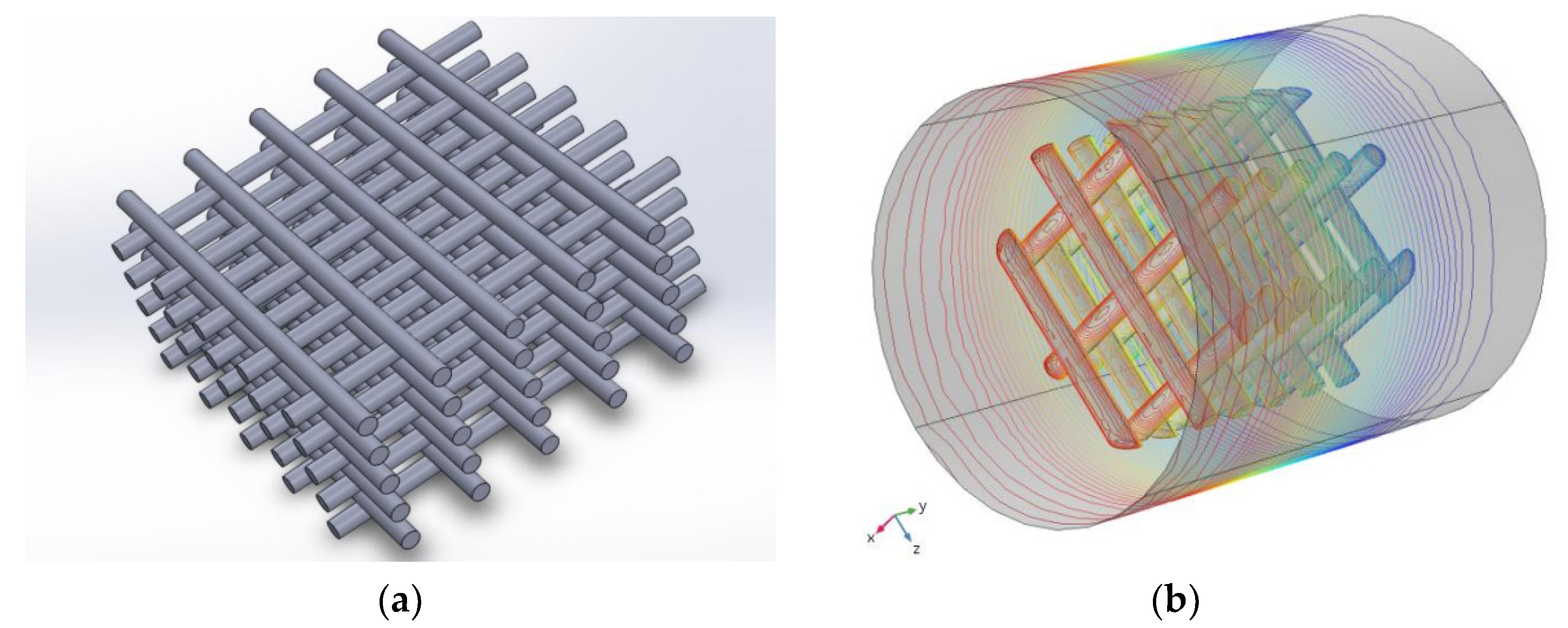
2.3. Computational Analysis

Theory Background for Computational Simulation

Fluid Mechanics models have been used to determine the fluid behavior in the bioreactor system, and to describe the characteristics of the fluid–dynamic systems. Comsol software computational modules work with laminar flow principles, solving equations that are at the core of fluid flow modeling, which include the Reynolds number to describe the flow conditions and Navier–Stokes equations to model the motion and the velocity of the fluids [32]. For this investigation, equations were solved for an incompressible laminar flow through the tube of the bioreactor. Comsol Multiphysics 5.2a, CFD Module, and Particle Tracing Module were used for the computational analysis of a bioreactor system that contained scaffolds loaded with cells (particles) flowing in the medium. A simple model has been chosen to evaluate the applicability of the output in practice and to compare the theoretical results with the experimental ones.
The scaffold’s geometry for the simulations was designed in Solidworks 2016 by Dassault Systems. The designed scaffold was multilayered. According to the experimental setup, the scaffold was computationally designed to fit in a 6 mm diameter tube and its virtual dimensions were as follows: pore size 1.5 × 1.5 mm2, fiber diameter 0.5 mm and 5 mm thickness. The key varying parameters in the model were inlet velocity, inlet particle number, and stimulation time (Table 1).
The cell culture medium was considered the cell culture salt mixture solution (a-MEM), at 37 °C (with a viscosity μ of 10−3 Pa·s and density ρ of 1000 kg/m3), and was treated as a continuous medium in Navier–Stokes and the continuity equations. The fluid was the main phase that carries and drives the motion of the dispersed phase representing the cells. In the case of the cells, simulation of the inert spherical particles with a diameter of 10 μm and density of 103 kg/m3 were programmed.
Two-steps simulation was conducted. Firstly, the velocity and the pressure profiles were acquired by solving a laminar fluid flow in the tube. Afterwards, the module of Particle Tracing for Fluid Flow was used to find the particle trajectories on the 3D scaffold. The following tasks were accomplished to simulate cell seeding in the 3D scaffold while they were in the bioreactor:
  • Import of the geometry designed in Solidworks.
  • Design of the bounding cylinder.
  • Selection of laminar flow and stationary study.
  • Insertion of the appropriate parameters for fluid properties, inlet velocity, zero outlet pressure, and non-slip conditions for the tube walls and the scaffold’s walls.
  • Design of the mesh (triangular for the scaffold walls and tetrahedral for the remaining tube).
  • Running of stationary simulation.
  • Insertion of a time-dependent particle tracing for fluid flow.
  • Insertion of the appropriate parameters for particle properties, inlet number of particles, drag force, freezing particles’ condition for the scaffold’s walls and the outlet.
  • Running of a time-dependent simulation.

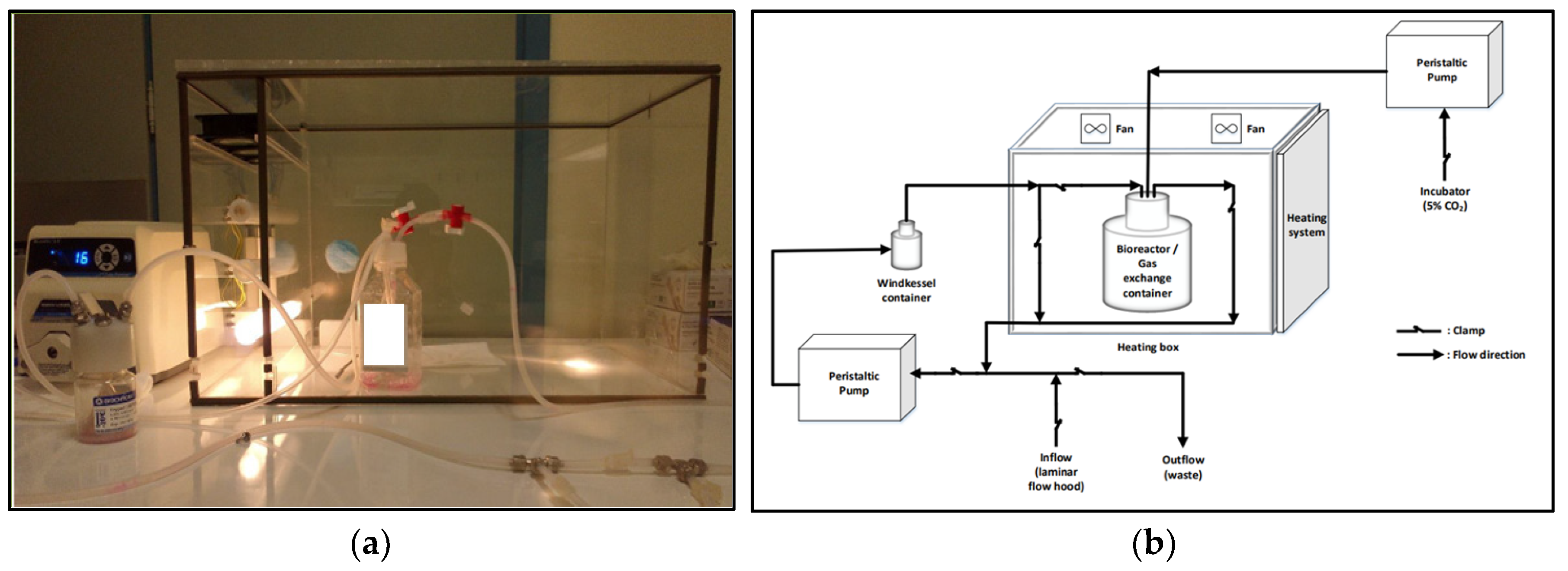
2.4. Bioreactor Setup

A custom-made bioreactor was employed in order to achieve the dynamic cell culture as depicted in Figure 2. The culture medium passed through the peristaltic pump into the Windkessel chamber, thus ensuring a smooth fluid flow, and continued into a container, where the cells were cultured in scaffolds. One peri-staltic pump (Masterflex© 2023-12, Gelsenkirchen, Germany) ensured the steady flow of culture medium, while another peristaltic pump (Masterflex© 2023-25) ensured the constant 5% of CO2 level. The flow rate of the first pump was set at 1.7 mL/min (or 7 rpm in a 4.3 mm diameter tube). Culture medium was poured into the system via a by-pass network, that started from a funnel, passed through the pump, the Windkessel chamber, and the container, until the total system was filled with the adequate quantity of medium. In a similar way, the waste was discarded from the system in the disposal container at the end of each experiment. The diversion of the flow to the desired tubes was achieved with clamps or 3-way valves (LABOPLAST®). The tube was fabricated from high-quality pumps to withstand the loads (Masterflex© 20230-24). The Windkessel chamber was manually constructed. The temperature was controlled at 37 °C via a custom-made electronic system. It should be mentioned that the system was sterilized meticulously before and after experiments; the sterilization protocol included cleaning with distilled water, followed by cleaning with 70% ethanol, and by UV exposure. Phosphate-buffered saline solution was finally used before pouring culture medium. The variants were as follows: (1) Cell number: 5 × 10⁴/105/2.5 × 105; (2) Incubation time: 0.5/2 h and (3) Inlet velocity: 3/6 mm/s.

2.5. Cell Culture

WJ-MSCs were isolated from the human umbilical cords (hUCs) that were delivered by the Hellenic Cord Blood Bank (HCBB). In the current study, hUCs (n = 10) derived from full-term (gestational ages 38–40 wk) normal and caesarian deliveries, were used for the isolation of the WJ-MSCs. Cells were isolated according to the protocol which has been previously described in detail by Chatzistamatiou et al. [33] and complies with international ethical standards and local ethics rules. Cells were incubated in an appropriate culture medium to promote their osteogenic differentiation, consisting of a-MEM supplemented with 10% FBS, 2 mM l-glutamine, 1% v/v amphotericin B, 0.5% v/v gentamicin, 50 μg/mL l-ascorbic acid, 10mM β-glycerophosphate, and 10−7 M dexamethasone (Sigma Aldrich, St. Louis, MO, USA).
Cells were seeded on the testing substrates at a density of 50,000 cells/cm2. The seeding procedure consisted in diluting the cells in a small quantity of cell culture medium (100 microliter/sample). Samples were placed in 24-well plates. The cell-containing medium was deposited on each sample through micro-pipetting. Samples were incubated for three hours to allow the adhesion to the substrate. After that, cell culture medium was added to each well until the sample was covered. Tissue Culture Plastic (TCP) was used as control material. The medium was regularly changed after post-plating, every 3 days.
The MTT reduction assay was used to evaluate cells viability for different incubation periods. A 5 mg/mL solution of MTT (Sigma) was diluted to a 1:10 ratio in serum free medium, as indicated in the guidelines. Scaffolds with seeded cells were transferred to a new well, washed with serum free medium, and incubated with 500 μL MTT solution for 3 h. Then, the MTT solution was removed and 500 μL of DMSO was used to dissolve the formazan crystals. From each sample, 100 μL solution was added in a 96-well plate in triplicate and the absorbance was read at 570 nm. Mineralization was evaluated by Alizarin Red S staining after 1 and 3 days of culture. Cells were fixed with 4% paraformaldehyde for 15 min. For staining, scaffolds were immersed in a 2% alizarin red S (Sigma) solution for 20 min and rinsed with distilled water until no more dye was released. Sample micrographs were obtained using a stereoscopic microscope. Results were also quantified according to the procedure described by Gregory et al. [34]. Briefly, each scaffold was incubated with 10% acetic acid for 30 min and the supernatant was transferred to an Eppendorf tube which was then vortexed and heated at 85 °C for 10 min, while being covered with parafilm to avoid evaporation. After complete cooling, the pH was adjusted using 10% ammonium hydroxide and the absorbance was read at 405 nm.
For cells imaging with a scanning electron microscope, scaffolds were washed with PBS and cells were fixated with a 1:1 Glutaraldehyde 4% v/v and Paraformaldehyde 4% v/v mixture for 20 min. Samples were washed again with PBS, dried, and gold sputter coating was applied for the SEM imagining of the cells in the scaffolds. A JSM-6610 Series Scanning Electron Microscope (SEM) model has been used for imaging.
For the ELISA measurement, cells were removed from the scaffold through prolonged Trypsination and centrifugation in 15 mL tubes (10 min, 1700 rpm).
ELISA kits from DLDEVELOP, DLR-OC-Hu, and DLR-OPN-Hu were used according to guidelines to quantify the levels of human osteocalcin (OC) and human osteopontin (OPN) in the cells deposited in scaffolds. For the measurements of the total protein (TP), the Pierce™ Coomassie (Bradford) Protein Assay Kit was used. The detergent employed to break the cellular membrane for the measurement of Total Protein was TRITON X (0.5%). An Infinite F200PRO UV/visible Spectrometer was used to detect the OC and OPN levels at 450 nm and the TP levels at 595 nm.
The FAK100 Sigma-Aldrich Actin Cytoskeleton/Focal Adhesion Staining Kit was used to stain cells on materials for confocal imaging. A confocal device Leica TCS SP5 with a Leica DMI6000B microscope—63× lense has been used. All results are expressed as mean ± standard deviation. Statistical analysis was performed using Student’s t-test and differences were considered significant when p < 0.05.

3. Results

3.1. Computational Analysis

Computational fluid dynamics (CFD) modeling is an effective tool for modeling flow in medical applications and devices. It has been used extensively to simulate hemodynamics within blood-contacting medical devices. Using CFD modeling for virtual testing in parallel with physical testing methods allows scientist to accelerate the development cycle, reduce costs, and validate innovative biomaterials safety and effectiveness with less animal model or patients testing. In this study, achieving an appropriate design of a bioreactor working conditions was important to have control on the cell culture environment by adjusting variables such as fluid velocity, exposure time, and arrested cell number, among others. Comsol software allowed the prediction of cells behavior in specific conditions, when loaded in a scaffold, and stimulated in a dynamic bioreactor. The images in Figure 3 show Comsol-generated graphs.
The Navier–Stokes equations and the continuity equation were used in the model to determine the velocity field in the flow and the number of attached particles in time:
ρ ( u ) u = [ p I + μ ( + ( u ) T ] + F
ρ ( u ) = 0
These equations were solved for incompressible laminar flow through the tube of the bioreactor. The virtual structure of the scaffold (Figure 3a), scaffold positioning in the bioreactor tube (Figure 3b), as well as the particle distribution along ‘xz’ and ‘yz’ axes (Figure 3c,d) for the conditions—2.5 × 10⁵ particles, 3 mm/s velocity, for 30 min stimulation in bioreactor may be seen. It is important to mention that the model refers to fluid dynamics and inert particle distribution, but it cannot predict the biochemical processes involved in the cellular adhesion. Despite that, it is important to understand the physics of the phenomenon and the probability that cells anchor to the scaffold’s fiber without any biological signaling, which is actually what happens in reality within the first moments after implantation. Cells float in in body fluids; the blood proteins are initially coming in contact with the surface of the biomaterial and enable biorecognition, which may take minutes to hours [35]; after this is accomplished, cells attach to the implant surface. In the meantime, the only way that cells can be entrapped in a scaffold is by physical forces. Therefore, this type of computational modelling provides important information about the type of interaction between scaffold and cells within the first minutes of exposure to a dynamic micro-environment such as the bioreactor or the human body.
As observed in the diagram in Figure 4, Comsol modelling predicts that the number of attached cells to the scaffold considerably increases proportionally with the inlet velocity. After approximately 20 min of stimulation, for 1 mm/s velocity the prediction indicates an approximate number of 500 cells in the scaffold, for 3 mm/s there will be a number of approximately 700 cells in the scaffold, and more than 850 cells are going to be entrapped in the scaffolds when the inlet velocity is 6 mm/s. The model indicates that the threshold for cells attachment is at 17 min exposure in the bioreactor. After that, the number of cells in the scaffold does not change drastically with time, being maintained constant in the case of all the applied inlet velocities. Since the Comsol model cannot offer data about the integrity and well-functioning of the cells, we may conclude that the number of remaining cells in the scaffold is described by the model as the number of anchored cells in the 3D structure within a maximum of 140 min exposure to the bioreactor. The highlight of the output is that higher inlet velocities will promote cells adherence to the fiber of the scaffold.
The diagrams in Figure 5 show the predicted distribution of cells depending on the initial number of cells in the fluid and on the inlet velocity. As it may be seen, the number of cells that come in direct contact and attach to the scaffold is considerably lower than the initially introduced cell number. For example, from an initial of 5 × 10⁴ cells, only 240 to 300 cells attach to the surface of the scaffold. The physical explanation is that the shear stresses and the flow intensity carry the cells through the pores of the scaffolds, leading to their loss with the fluid. From the huge particle number that are given as an input, only 1.5% stay on the fiber. This prediction fits the reality, since it is well known that cells find it difficult to adhere to 3D scaffolds and that even for static conditions, an adapted protocol involving coating with adhesion proteins is needed to obtain an efficient result. This issue is further developed in the discussion in Section 4.
We may observe that independently of the initial cell number, there is a tendency that the cell distribution decreases along the thickness of the sample, as we analyze layers 2 to 5 (Figure 5a–c). The distribution of the cells is optimum on a 2D material (one layer). This is normal because they expand uniformly on the available area and populate it entirely. The cell type and dimensions, as well as the scaffold pores dimension, influences the distribution. In this case study, cells were considered particles with 10 μm diameter, which is a normal dimension specific to well-developed bone cells, while scaffolds fibers and pores were on the millimeter scale. In a 3D scaffold, the well-developed cells with 10 μm diameter may go through the pore or stop in the scaffold fiber and start the biorecognition process for adherence. The model predicts that cell number is reduced in the advanced layers of the 3D structure; more precisely, cell number is drastically reduced starting with the second layer, and then stabilizes until the fifth layer. This means that within this time duration of exposure to a bioreactor (140 min), the distribution becomes less efficient between the second and the fifth layer of the scaffold. The local stress concentration developed due to a reduced area of fluid flow through the pores of the scaffold represents an obstacle for the homogeneous distribution of the cells in the structure and dislocate cells throwing them back into the flow. The valuable outcome that can be extracted from the diagram is that the distribution of cells within layers 2–5 will tend to be random or restricted because of physical reasons, but this situation is overcome as more layers are added. In addition, as observed in the diagrams in Figure 5, for all initial cell numbers, the distribution of the cells is more efficient as the inlet velocity is higher (6 mm/s). Further, it may be observed that in all cases (Figure 5a–c) the initial number of cells that are distributed in the first layer reduces to half cells in the fifth layer. Thus, for a population of 5 × 10⁴ initially introduced cells, the 300 cells in the first layer will be reduced to 150 cells in the fifth layer, and for a population of 105 initial cells, the 600 cells will end up in 300 cells in the fifth layer, while in the case of 2.5 × 10⁵ cells, they will decrease from 1500 to 800.
The output of the above computational results offers information about two theoretically calculated parameters that may be optimum for the experimental setup: (1) the inlet velocity of 6 mm/s and (2) the initial cell number—2.5 × 10⁵.
The cell attachment is the key process that will determine the biorecognition of the scaffold by the cell population. The biologic dimension of the attachment process cannot be described through the present model, but the physical events can predict in some extent the interaction and the maintenance of the cells within the 3D structure. During the flotation process, a solid particle approaches a surface, and an attachment or a driftage of the particle takes place. Various essential types of interaction may occur: (i) colliding (impact), in which the particle could be deformed and remains on the material, or (ii) colliding and rebound followed by floating, (iii) sliding across the surface and continuing floating, or (iv) colliding to the next layer of the scaffold. The model analysis these scenarios by predicting the final number of attached cells for different initial cell numbers and inlet velocities. It can be observed (Figure 6) that a higher number of initial cells (2.5 × 10⁵) and a higher velocity (6 mm/s) will lead to an improved result in terms of cells attachment to the scaffold. From a physical viewpoint, the phenomenon is related to the dynamics of the initially powered cells through the tube towards the scaffold, which due to an increased velocity are propagated and impact the scaffold surface with higher chances to attach to it.

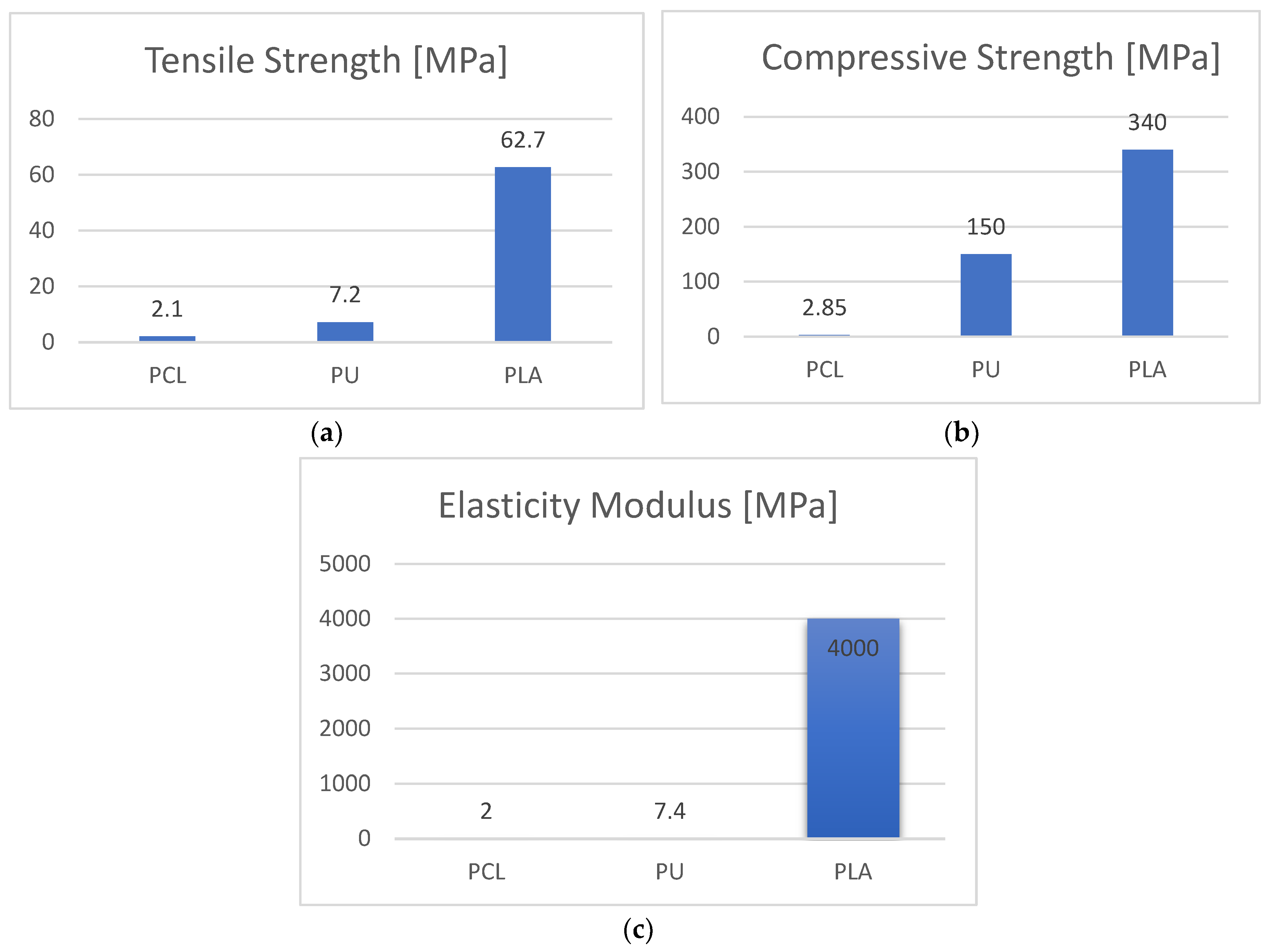
3.2. Mechanical Evaluation of the Scaffolds

The texture, geometry, and dimensions of the scaffolds may be seen in Figure 7. Scaffolds were mechanically evaluated: electrospun scaffolds were subjected to tensile testing, while 3D printed scaffolds were tested in 3-point bending.
Due to their good elastic properties and because their structure does not allow testing in compression, electrospun scaffolds were tested in a tensile mode, while 3D printed scaffolds were evaluated through compression because of their perspective application as synthetic bone grafts. Figure 8a,b show the mechanical properties of the scaffolds before and after sterilization, with more significant differences in the case of the electrospun scaffolds (Figure 8a) caused by their fragile nature.
A significant difference between the compressive modulus of PLA (300 MPa) and PU (25 MPa) was found, which was expected. PU material showed higher strain at failure. PLA specimens showed an initial linear elastic behavior followed by plastic deformation up to the maximum load, while PU behavior was nonlinear rubber-like during the entire loading procedure.

3.3. Stem Cells Feedback to Scaffolds in a Bioreactor

The evaluation of the computational predictions has been experimentally conducted firstly on the electrospining PCL materials. Stem cells were loaded in electrospun scaffolds and exposed to a bioreactor; based on the output of the first experiment, the setup was adjusted for further investigation of cells behavior when loaded in 3D printed scaffolds and exposed to a dynamic flow. Results are presented below.

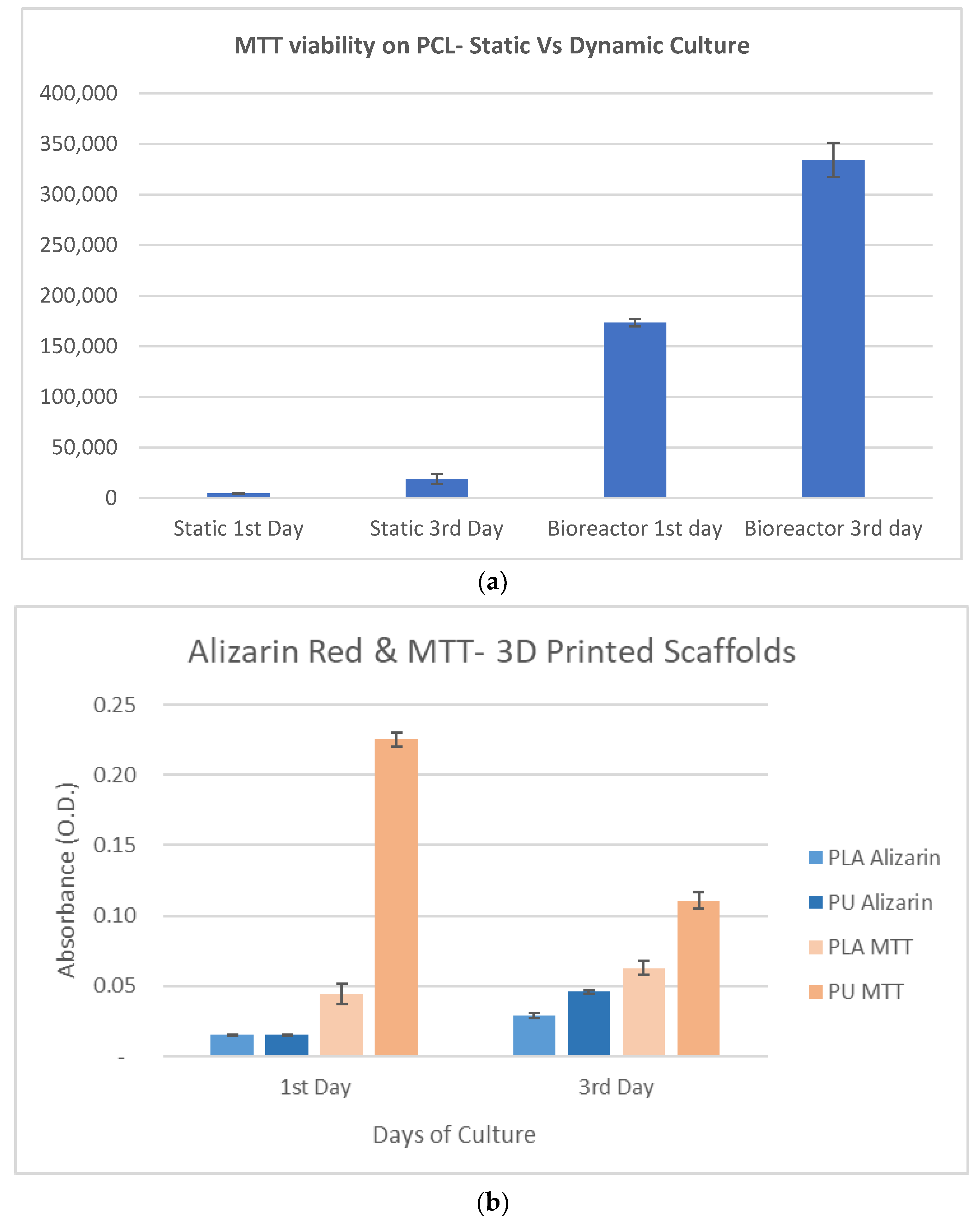
3.3.1. Experiments with PCL Electrospun Scaffolds

The first set of experiments was performed with the aim to measure the number of attached cells in the scaffolds depending on the inlet velocity, the initial number of cells introduced in the experiment with the cell culture medium, and the exposure duration (0.5 h and 2 h). The experimentally tested inlet velocities were 3 and 6 mm/s. As observed in Figure 9a, for a short exposure time of 0.5 h in the bioreactor, the number of attached cells increased for both cases, 3 and 6 mm/s inlet velocities. More precisely, for both inlet velocities, the initial numbers of introduced cells of 5 × 10⁴ cells, 105 or 2.5 × 10² almost doubled with time. This situation changed when measurements were performed for 2 h exposure. We may observe that for short exposure time (0.5 h), the cell number increases, and the trend is similar for both 3 and 6 mm/s inlet velocity, which is not the same for longer exposure time (2 h). For 2 h exposure time and high velocity (6 mm/s), the number of attached cells does not increase with the initially introduced cell numbers. It can be assumed that the projection of the cells on the fiber wall is too intense at 6 mm/s and this leads to their immediate dislocation. Competitive attachment between cells at high cell numbers may also be the cause of inefficient adhesion to substrate. The most efficient attachment in the diagram in Figure 9a is in the case of 2 × 10⁵ introduced cells and 3 mm/s inlet velocity, for an exposure time of 0.5 h.
The experimental vs. computational results (3 mm/s velocity) may be seen in Figure 9b. The computationally predicted number of attached cells is much lower than the experimental one in all cases. Obviously, this is because the computational equations take into consideration the physical processes involved in cells’ attachment and not the biological ones. The theoretical study predicts well the tendency of attached cell number to increase proportionally with the initial number of introduced cells in the experiment, for a short exposure time in the bioreactor (0.5 h) at 3 mm/s velocity. The computational results do not match when applied to longer exposure duration (2 h), indicating that the biochemical cellular processes play the main role in the long-term adaptation of cells to substrates, in dynamic conditions.

3.3.2. Experiments with PLA and PU Printed Scaffolds

The diagram in Figure 10a demonstrates the importance of a dynamic environment for the well-functioning of the cell population. The PLA scaffolds have been used to compare the viability of cells (MTT test) in static and dynamic cultures. Cells were deposited in PLA scaffolds and incubated for 1 and 3 days. Samples tested for response to dynamic conditions were maintained in a bioreactor for 0.5 h duration, five hours before the MTT measurements. The viability slightly increased from 1 to 3 days of incubation in static conditions, and it was doubled from the first to the third day of incubation after exposure to a dynamic micro-environment. The viability values for cells exposed to bioreactor (3 mm/s inlet velocity, 0.5 h) was incomparably higher than in the case of the static experiment. This test proved the importance of applying an in vitro dynamic micro-environment for the cell culture proliferation and its potential regarding in vitro tissue formation.
Based on the computational observations, some in vitro parameters were adjusted with the purpose to optimize the in vitro micro-environment and to obtain positive feedback from the cells when they are seeded in 3D printed scaffolds and under dynamic conditions. The experiment in the bioreactor was preceded by the seeding of cells in the scaffold and maintenance for 1 and 3 days of incubation, in static conditions. The reason for this preparatory step was the nature of the 3D printed scaffolds which, comparing to the electrospun scaffolds, are stiffer, with larger pores; this determines, as predicted, a loss of a high cell number that could be caused by cells rebounding when they come in contact with the fiber and their floating away through the pores, with the fluid. Given the extended experimental duration, the number of deposited cells was reduced from 2 × 10⁵ to 105 to offer them expansion area for appropriate proliferation with time. After the first and the third days of incubation in the scaffolds, cells were exposed to the bioreactor for 0.5 h at 3 mm/s and then MTT and Alizarin red tests were performed. The diagram in Figure 10b shows that the exposure to the bioreactor lead to a small increase in cell viability in the case of the PLA, while for the PU scaffolds, the viability decreased in the third day. This is related to how cells adapt to the substrate with time. Since the structure of the PLA and the PU scaffolds is identical, the parameters that enable a different response in cells are their physical and mechanical properties. On the other hand, analyzing the Alizarin quantity in cells (Figure 10b), we observe that the mineralization process is weak in cells after one day of incubation on both materials, but it is pronounced after 3 days of incubation, especially for the PU. Knowing that the multiplication and the mineralization processes are competitive, these results are complementary.
In the images in Figure 11a,b we may see the scaffolds loaded with cells and stained with Alizarin red. The color of the stained cells in PLA and PU scaffolds is intense, indicating an active mineralization process, especially for the PU. Cell-loaded scaffolds exposed to the same incubation and bioreactor conditions were used in parallel with the specimens used for Alizarin Staining. The purpose was to observe the cell evolution in each scaffold, and understand their behavior. As observed comparing the images Figure 11c,d, the cells in the PLA scaffolds present less pronounced projections, visible especially at the bridging point between the fibers. In addition, in the PLA scaffolds, cells have the tendency to create conglomerates, thus partially mimicking the steps in their in vivo mineralization cycle. Bone, in addition to its structured extracellular matrix of inorganic and organic elements, contains a conglomeration of cell types that continually monitor and modify the bony structure in response to the ever-changing mechanical stressors [36]. In this case, the stiff nature of PLA enables a type of premature mineralization comparing to PU, where cells can be observed expanding on the entire fiber area (Figure 11d).
In order to better understand cell feedback to the two types of 3D printed scaffolds, in the presence and in the absence of the bioreactor, the total protein, osteocalcin, and osteopotin levels were measured (Table 2, Figure 12) in cells that were incubated for three days. Exposure to a bioreactor was performed for 0.5 h, 8 h before the measurements.
Regarding the total protein levels, the adhesion of cells to the substrates takes place through adaptive processes and it is mainly dictated by the biomaterial properties, in between which the elasticity modulus plays a crucial role. PLA has a high elasticity modulus and induces spontaneous adhesion of cells to the substrate, in static conditions. However, cells migrate better on a softer substrate such as PU, which is proved also by the MTT results; in any case, their adhesion and connection to softer substrates is less strong than in the case of stiffer substrates (PLA in this case). The bioreactor induces better adhesion of the cells in the PU scaffolds, stimulating them to oppose resistance to detachment. Osteopontin is an extracellular structural protein, and it is expected to be higher for a higher number of adherent cells. Osteopontin is a valuable biomarker induced by the bridging between cells and the strength of the attachment to the substrate. Viability of cells in PU scaffolds has been found considerably higher comparing to PLA scaffolds. However, given that the adhesion is not strong, osteopontin value is not higher than in cells in PLA scaffolds, where adhesion is more pronounced. We may observe an interplay between quantity and quality of adhesion, which determines the final osteopontin value. The osteocalcin level is higher in cells in PLA scaffolds under static conditions, because the stiffness of the material induces spontaneous differentiation of cells determined by the enhanced adhesion. This is reversed through the introduction of the stresses applied by the fluid flow in the bioreactor. Since the adhesion threshold has been reached in static conditions, the additional stresses developed through the fluid flow contribute to the differentiation of the cells and forces them to enter in the mineralization phase. Regarding the PU, MTT levels in cells on PU indicate the occupation of the scaffold in its entire mass. This happens fast on PU comparing to PLA because the migration of cells is not limited by strong adhesion. The lack of space after prolonged incubation reduces cells viability and enables mineralization because of confluency. Alizarin red level substantially increases in cells on PU after 3 days of incubation, with bioreactor stimulation.
The SEM images in Figure 13 show cells morphology in the scaffolds. Comparing the cells developed in the PU scaffold (Figure 13a,b) vs. those developed in the PLA scaffold (Figure 13c,d), we may observe that the ones in PU are more expanded; as a consequence, they may be observed at lower magnitudes. Cells actines in PU scaffolds bridge the fibers of the scaffold (Figure 13b) and create a compact mass. Cells in PLA scaffolds also develop actines (Figure 13d) on and between the fibers, but they are less visible at low magnitudes showing that their number and density in the scaffold are decreased. After exposure to a bioreactor, cells occupy the entire surface of the PU scaffold (Figure 13e) to an extent that makes the observation of the fibers and of the pores much more difficult, thus confirming the above interpretation on their confluency and lack of space in the scaffold. The cells layer on the PLA fiber (Figure 13f) after exposure to bioreactor is less dense and it can be observed at much higher magnitude than those in PU. In addition, comparing images of cells in PLA scaffolds before (Figure 13d) and after (Figure 13f) exposure to a bioreactor, we may observe that the actines are less expanded, confirming that for the above-mentioned reasons related to strong adhesion, premature differentiation, and mineralization, cells activity is affected in a dynamic environment.
Confocal images of cells in PLA and PU scaffolds may be seen in Figure 14. The actins of the cells in the PLA scaffold were less expanded and developed than in the PU scaffold, confirming the SEM results. In addition, in the images in Figure 14b,c we may observe cells bridging on the different levels of the scaffold; cells are more compact and aligned in the PU scaffold comparing to the PLA scaffold.

4. Discussion

The purpose of the computational investigation conducted in this study was to elucidate aspects of the experimental setup. The proposed parameters (stimulation time, cell number, inlet velocity) are of critical importance for the in vitro environment that should be similar to the physiologic one, and allow growing cell cultures until they will eventually promote the formation of a tissue. Several aspects related to 2D cell cultures have not yet been clarified, and 3D scaffolds for cell growth complicate the situation even more as they introduce new parameters such as the migration of the cell population into the scaffold. Although migration principles are focused on cells moving on two-dimensional (2D) substrates, there is now a great deal of interest in single-cell movement in three-dimensional (3D) tissue environments. Most migration modes previously observed in 2D environments also occur in 3D tissue environments. However, because the distribution of ligands in 2D is generally much more uniform than in 3D matrix models, cell morphology is quite different in the two environments. In 2D cell culture, fibroblasts have large lamellipodia and filopodia. By contrast, fibroblasts in 3D collagen gels exhibit both smaller and fewer lamellipodia and filopodia [37]. These observations [32] were made previously by research groups who studied cell populations under static conditions. A dynamic micro-environment will cause a change in cells response. Their natural, physiologic environment is a dynamic one. A continuous exchange of blood elements and nutrients cause both floating and flowing of biochemical substances together with different cell types in the body. Adherend cells such as stem or bone cells are looking for an appropriate substrate to sit on. This process can be enabled only upon biorecognition. While biorecognition is simple under physiologic conditions with no trauma, the insertion of the implant after damage of a tissue demands adaptation to a foreign material and tissue repair. In such a condition, the biological adherence will take time and chances for cells to sit on an implant or to populate its 3D structure depend on the fluid dynamics of the micro-environment.
The performed computational modeling (Figure 4) indicates that the number of deposited cells increases with time. Within the first two minutes, the initial number of cells introduced in the experiment which attach to the scaffold decreases considerably until it reaches a threshold and then it stabilizes. From 20 to 140 min the number of cells remains almost constant for any inlet velocity. In reality, the first minutes of contact between cells and a foreign material or micro-environment are of great importance. It has been shown that once attached through physical forces, cells initiate an adaptation or rejection process. The phenomena related to cells response within seconds or minutes after contact has raised questions many years before and several issues have not been yet clarified [38]. However, a recent study with monocytes showed how some cellular processes are initiated very fast in the cells, even before strong bonding between them and the substrate takes place; though the cell cycle was arrested, cells failed to complete differentiation without adhesion, but it has been confirmed that early signaling events (within 15 min of stimulation) were independent of adhesion [39]. Our computational modelling shows that physical forces contribute to the adhesion of a number of cells to the scaffolds within the first minutes after contact. Exposure time to bioreactor, inlet velocity, and the initial number of cells introduced in the culture medium will determine the final number of attached cells to the scaffold. The output offers useful information that can further help calculating the rate of in vitro tissue growth.
In the diagrams in Figure 5, it has been shown that a higher number of cells involved in the experiment will determine an increased number of deposited cells in the scaffold, which is expected. However, the model predicts that most of the cells are lost and do not end up growing in the scaffold. Only 1.5% cells attach to the substrate according to the model prediction. It is well known that static seeding on 3D additive manufactured scaffolds fabricated from thermoplastics still remains an issue, as it often results in poor cell attachment, high cell sedimentation, and non-uniform cell distribution, due to gravity and to the intrinsic macroporosity and surface chemical properties of the scaffolds [40]. Seeding protocols have been developed under static conditions; cells are deposited in the scaffolds before being placed in a bioreactor or before being implanted. This condition partially reproduces the reality where, after the implant is introduced, is covered by blood proteins, followed by the extracellular matrix, and finally by the cells of the tissue that will adhere to the implant; meanwhile, new cells are released and are searching for an appropriate substrate to attach. However, this is a static scenario, while the performed modeling within this study considers the real conditions of the floating cells in a dynamic micro-environment and the limitation of this process in terms of adherence. Different cell numbers were used in this investigation to find the optimum conditions of cells seeding in scaffolds, in the bioreactor. Cells intensify communication depending on the distances between them; biochemical signals are transferred through the extracellular matrix and the culture medium. An increased cell number means improved communication. Nevertheless, many aspects related to the number of cells that should be seeded on the 2D surfaces have not yet been clarified in standard protocols and they are still under research; the 3D structures involve even more complex situations. Some conclusions have been drawn previously related to cells seeding on 2D substrates. Cells number shall be adjusted depending on both the available area of the substrate and its nature [41,42]. A larger number of cells in the fluid as predicted through modelling will assure a higher number of arrested cells in the scaffold. The computational output shows better results for higher cell number, based on the fluid dynamics principles. For a 3D structure, the model predicts that the distribution within the scaffold is less efficient between layers 2 and 4 and it stabilizes in layer 5 (Figure 5a–c) for all cell numbers introduced in the experiment. This is due to developed shear stresses concentration as the fluid passes through the pores with fluctuation of velocity that changes fluid directions and intensity of particle projection, making adherence difficult. Agglomeration of cells temporary diminishes their distribution along the thickness of the scaffold, a situation that is overcome after 2–3 layers when stresses are reconfigured.
Regarding velocity of the fluid, it has been stated after experimental observation that in vivo, a higher velocity of blood and interstitial fluid flow in the body will result in a greater amount of transferred nutrients [43]. These in turn will stimulate cell growth and will promote attachment, as well as multiplication. An increase in the inlet velocity in vitro determines more intense biochemical signaling that enhances connection between cells and, as a consequence, determines a faster multiplication rate. Finally, formation of strong bonds with the substrate, in time, will lead to normal development of the cell population and will generally contribute to the self-regulation of cellular processes. In this case, biorecognition is enabled and the scaffold is populated. The purpose was to find a threshold between the minimum and the maximum value of the inlet velocity, that will benefit cells development. Bones are highly vascularized, metabolically active tissues having an extensive network of blood vessels. Measurements in multiple animal species including humans estimated the proportion of cardiac output directed toward the skeletal system to be in the range of 5–15%. Such an enormous supply of blood indicates high nutrient demand, associated cellular processes, and the importance of blood vessels in bone and body homeostasis [43]. In an in vitro model, since vessels do not exist, blood and physiological fluids flow into the scaffold as provided through the culture medium,. Previous studies indicated that the local pressure gradients near the vascular canals are significantly amplified at higher loading frequencies. These amplified pressure gradients would drive the interstitial fluid to flow over the cell processes at a higher velocity, inducing larger hydrodynamic forces and causing the cells to have a higher sensitivity to high-frequency loading [44]. In the absence of the vessels in the scaffold, the medium will directly interact with cells and the cell population will adapt to the existing surrounding micro-environment. The flow of blood and interstitial fluid cannot be compared to the one in the natural tissue. However, the inlet velocity will influence cells response to this micro-environment. The computational model indicates that increased inlet velocities contribute to the proliferation of the cell population, which is explained through the above-mentioned in vivo findings. However, the performed in vitro experiments showed that a moderate tested inlet velocity (3 mm/s) was found appropriate because a higher tested velocity (6 mm/s) dislocates cells causing their loss in the flow instead of attaching to the scaffold.
Besides flow dynamics, initial cell number, and exposure duration to a bioreactor, are other important elements that contribute tremendously to the attachment of cells to a biomaterial; cells self-regulate their processes depending on the geometry of the scaffold, its pores dimension, its surface and mechanical properties such as roughness, elasticity modulus [28], and others. The present investigation had the purpose to reach this goal of understanding the effect of combined parameters and improving bioreactor conditions for the stem cells growth in a 3D scaffold. Another goal was to investigate the potential of several thermoplastic materials in promoting in vitro tissue growth. CNTs-reinforced electrospinning PCL scaffolds, as well as PLA and PU 3D printing scaffolds were fabricated and tested.
The mechanical properties of the CNTs-reinforced electrospun PCL scaffolds (Figure 8b) were comparable with those in literature [45,46]. These types of scaffolds have good tensile properties and extremely good biocompatibility for application in soft tissue repair. PCL scaffolds cannot be used in application where compressive performance is needed. That is why PLA and PU 3D scaffolds were fabricated to draw perspectives on their application for bone tissue repair. The compressive modulus of the PU is extremely low, in comparison to that one of the PLA (Figure 8b). The modulus of the two (Figure 8d) was found similar, with the highlight that PU comparing to PLA presents a rubber-like behavior, which places it in the category of elastic biomaterials. In this case, cells in PCL and PU scaffolds may behave differently than in PLA scaffolds, due to their lower tensile elastic moduli. It is known that stem cells have high adaptability potential and react to mechanical stimuli [47]. Cells feedback to the fabricated scaffolds offered answers related to the influence of the mechanical parameters on the biointegration process.
The evaluation of the computational results was firstly performed with the PCL electrospinning scaffolds (Figure 9). The ideal in vitro inlet velocity was 3 mm/s and not 6 mm/s, opposite to what was predicted by the computational model. The in vitro system presented lower efficiency at 6 mm/s inlet velocity with cells being lost, especially at higher initially introduced cell number. A moderate inlet velocity of 3 mm/s and a high number of initially introduced cells (2.5 × 10⁵) determined a higher number of attached cells. For 3 mm/s inlet velocity, the model predicted well the tendency of attached cells number to increase proportionally with the initially introduced cell number. However, the discrepancy between the extremely reduced number of attached cells predicted by the model vs. the final experimental number of attached cells shows that a more accurate modelling demands the introduction of biological factors related to cell attachment mechanism and not only the physical parameters characteristic to fluid dynamics. In this case, the applied computational modelling within this study predicted accurately the qualitative and not the quantitative events happening in the first minutes (until 20 min) from the moment the flow was enabled in the bioreactor. Once cells anchored on the material (after the first 20 min), the biological attachment was enabled, and results were no longer predictable with the Comsol software.
The testing of the PLA and PU scaffolds with MTT and Alizarin red was performed after exposure to the bioreactor conditions at 3 mm/s inlet velocity. The initial number of cells was 105; cells were seeded in the scaffolds in normal static conditions and incubated for 1 and 3 days before exposure to bioreactor. The bioreactor exposure was for 0.5 h, and five hours before the MTT and Alizarin red measurements. In the case of the PLA scaffolds, the cells viability increased on a small scale after 3 days of incubation (Figure 10b) while the Alizarin quantity was pronounced. For the PU, a significant decrease in cell viability may be observed after 3 days of incubation and a pronounced increase in the Alizarin quantity is detected. PU is characterized by appropriate tensile modulus similar to the natural tissue. Its mechanical properties are biomimetic comparing to PLA because they are closer to real soft tissue, which enable biorecognition by stem cells. Cells adapt rapidly and populate substrates that mimic their natural environment. Once the scaffold is fully occupied and there is no area for them to expand, the multiplication process is gradually stopped, and cells start their differentiation process. These two processes are complementary; it may be seen that the mineralization process is intense (Figure 10b). The multiplication rate of stem cells in the PLA scaffold is lower, but there is a parallel progress of both viability and mineralization. The mechanical properties of the PLA are less biomimetic, and this results in a reduced multiplication rate of the cells comparing to the PU; the multiplication process is complemented by a moderate mineralization activity for the PLA.
Analysis of important biomarkers (total protein, ostepcalcin, osteopontin) usually expressed in stems cells when exposed to differentiation conditions into bone cells allowed interrelating the environmental conditions and the cellular behavior. The applied stresses induced through the dynamic flow did not influence cells adhesion on PLA because the material stiffness has already determined a strong cells’ attachment to the substrate. The adhesion threshold of cells to the scaffold is reached in the case of the PLA in static conditions. In this direction, it has been previously shown that material stiffness is the key regulating factor in cells adhesion and adaptation to the biomaterial when in vitro [37,40]. However, the dynamic conditions introduce new parameters which enhance the type of cooperation between cells and substrate when the underneath material has biomimetic properties, similar to the real tissue. More precisely, the soft nature of the PU surface combined with the effect of the fluid flow determine both multiplication and strong adhesion of cells in this type of scaffolds. The bioreactor had no significant effect on cells in the PLA. Moreover, due to an interplay between quantity (number of cells) and quality (strength of adhesion), the same levels of osteopontin are expressed in cells in both types of scaffolds, for different reasons: in PU there is a high number of viable cells and weak adhesion while in PLA, there is a strong adhesion of cells and less proliferation. Osteopontin level increases significantly in cells in PU scaffolds with the addition of the bioreactor, which induces improved adhesion by making cells to oppose detachment. A high number of appropriately attached cells is the optimum biologic feedback and makes the combination ‘biomaterial stiffness-bioreactor stimulation’ decisive for tissue development and cooperation with the 3D scaffold. This proves that the stresses applied by the fluid dynamics strongly influence the quality of the adhesion in cells, especially on softer substrates.
Due to the exposure to the bioreactor, cells adhesion on PU was considerably enhanced, followed by an increase in osteopontin content. In this case, cells also went through an intense and active biomineralization process (osteocalcin level) because they reached confluency, which is confirmed with the Alizarin red test. The events took place differently in cells when seeded in the PLA scaffolds. The adhesion threshold was reached without bioreactor stimulation. The viability of cells was lower than in the case of PU. However, the substrate stiffness induces early differentiation. Osteopontin level increased with the addition of bioreactor stimulation. Mineralization continued, but not intensively.

5. Conclusions

A theoretical and an experimental investigation were performed to analyze a system containing 3D scaffolds loaded with cells and exposed to a bioreactor. Comsol software was used to theoretically adjust the bioreactor conditions and to understand the physical adhesion processes of the cells to the scaffolds. Analyses of experimental biomarkers expressed in cells when deposited in the scaffolds under different conditions allowed the evaluation of the theoretical predictions. The following conclusions were drawn:

5.1. Theoretical Conclusions

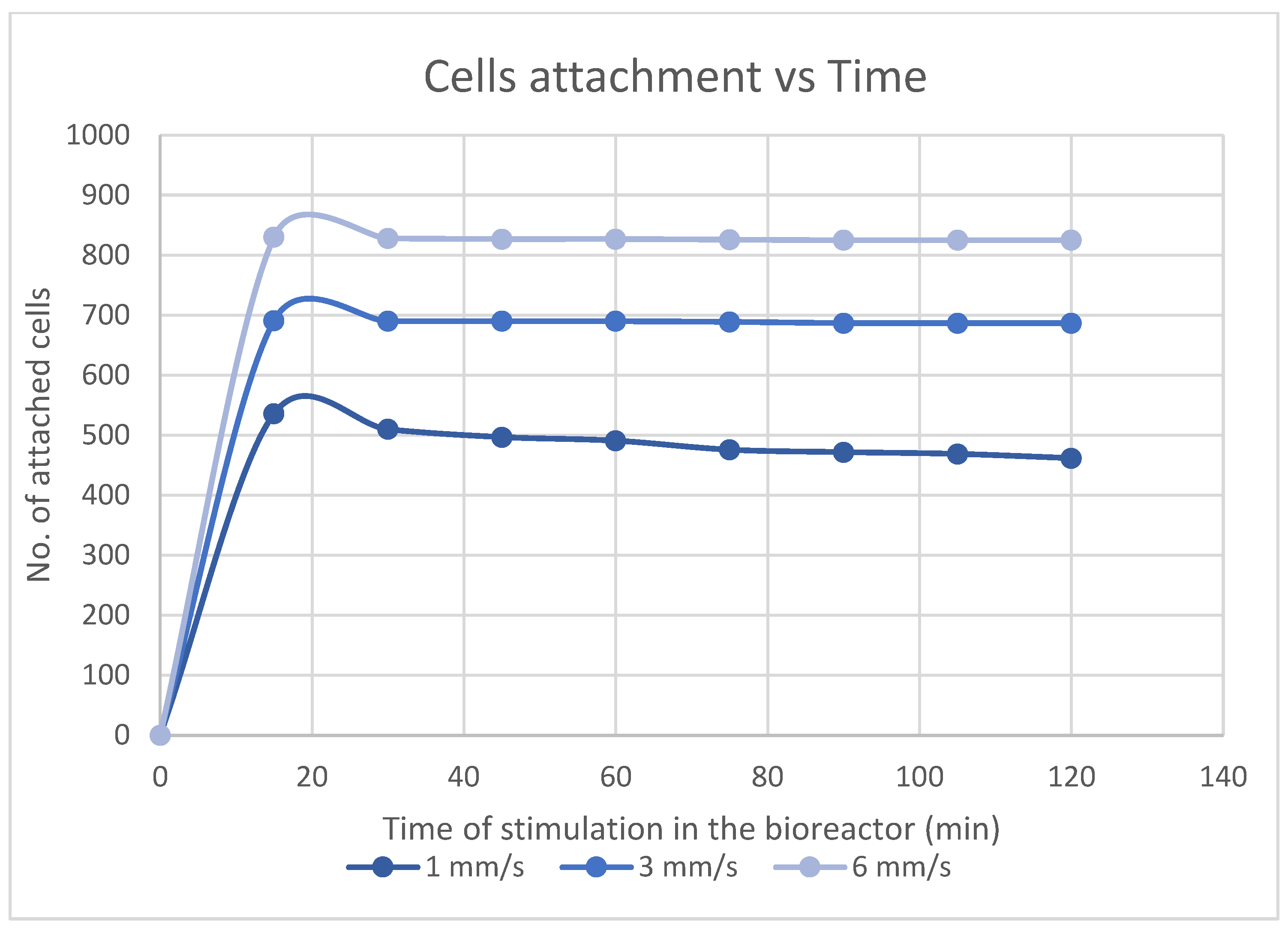
  • The physical parameters influencing cells deposition in the scaffolds under dynamic conditions (bioreactor) are decisive within the first 17 to 20 min for cells long-term proliferation and tissue formation. The Comsol software modelling is recommended to predict cellular events in scaffolds, in a bioreactor, within the first half of an hour after contact between cells and substrate. In addition, the Comsol model correctly predicted the events related to cells adherence at lower inlet velocity (3 mm/s).
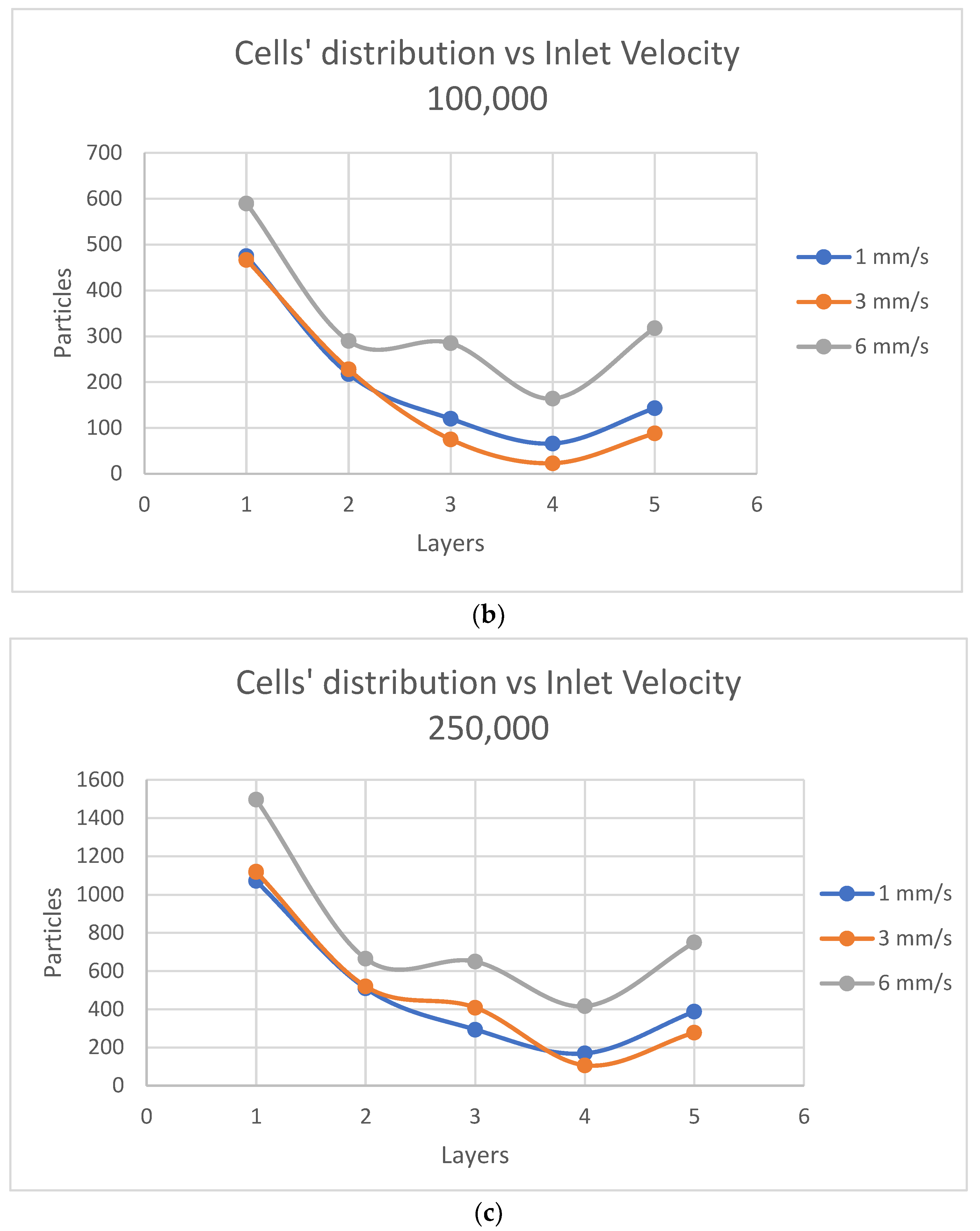
  • According to the Comsol findings, the shear rate increases in the space of the scaffold pores, while the fluid velocity doubles inside the scaffold, which determines some changes in cells distribution, making it less uniform and efficient between layers 2 and 5 of the scaffold structure.
  • Computationally, the inlet velocity of 6 mm/s proved to be the optimum in order to better distribute the cells on the scaffolds, but it did not coincide with the optimum experimental inlet velocity (3 mm/s). The reason is that the model does not account for the biological parameters which are crucial for cell attachment in the first minutes after contact with the substrate.
  • It was computationally predicted that only 1.5% of the inserted particles attach to the scaffold. Experimentally, a solution to avoid cell loss from the scaffold due to physical events is the seeding of cells on the substrates in static conditions and their subsequent incubation for hours to days, before the exposure to a bioreactor.
  • In the computational modelling, cells were assumed to attach to the substrate as soon as they hit the scaffold wall. In reality, the cell–biomaterial interactions are biologically complex and need to be taken into account.

5.2. Experimental Conclusions

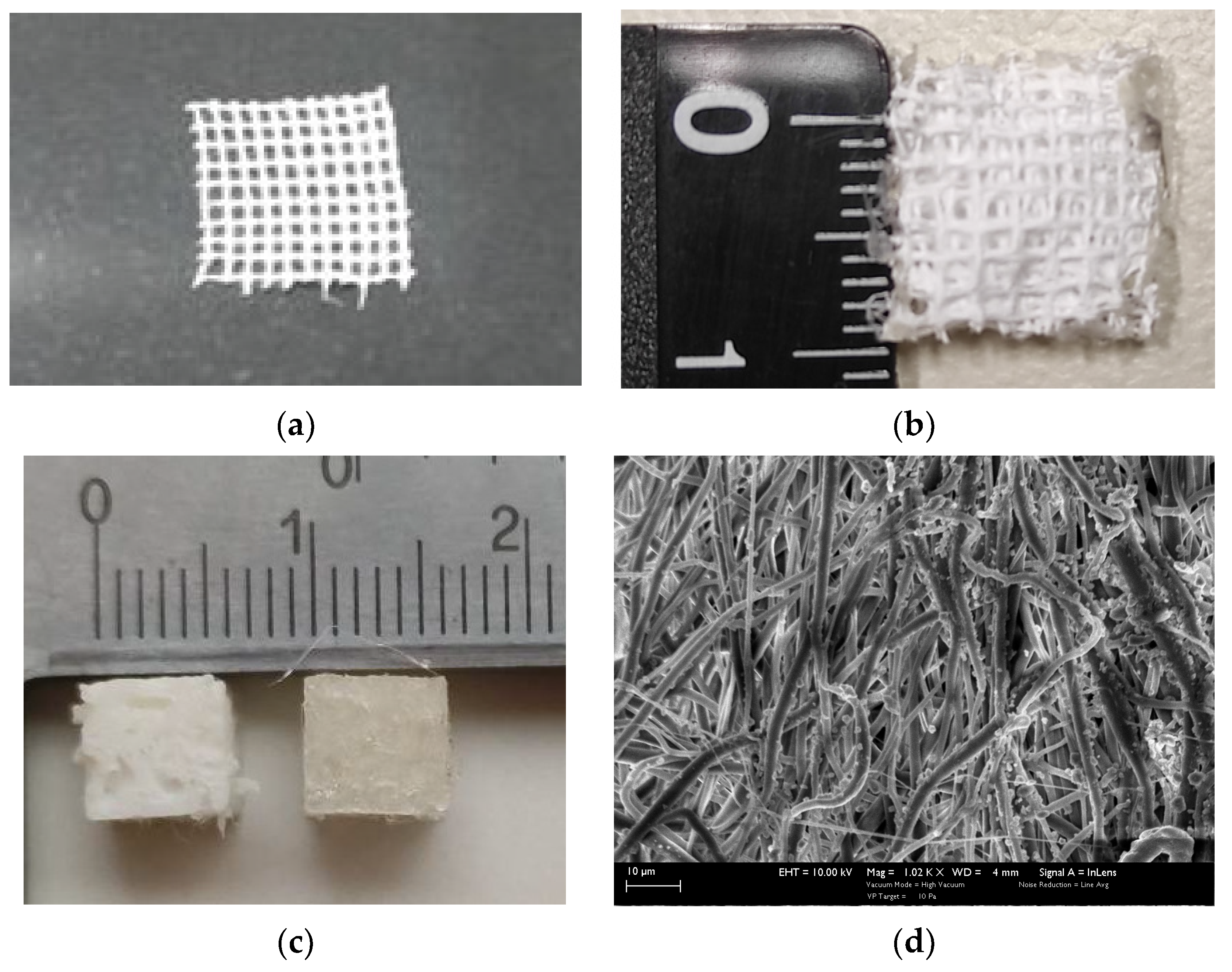
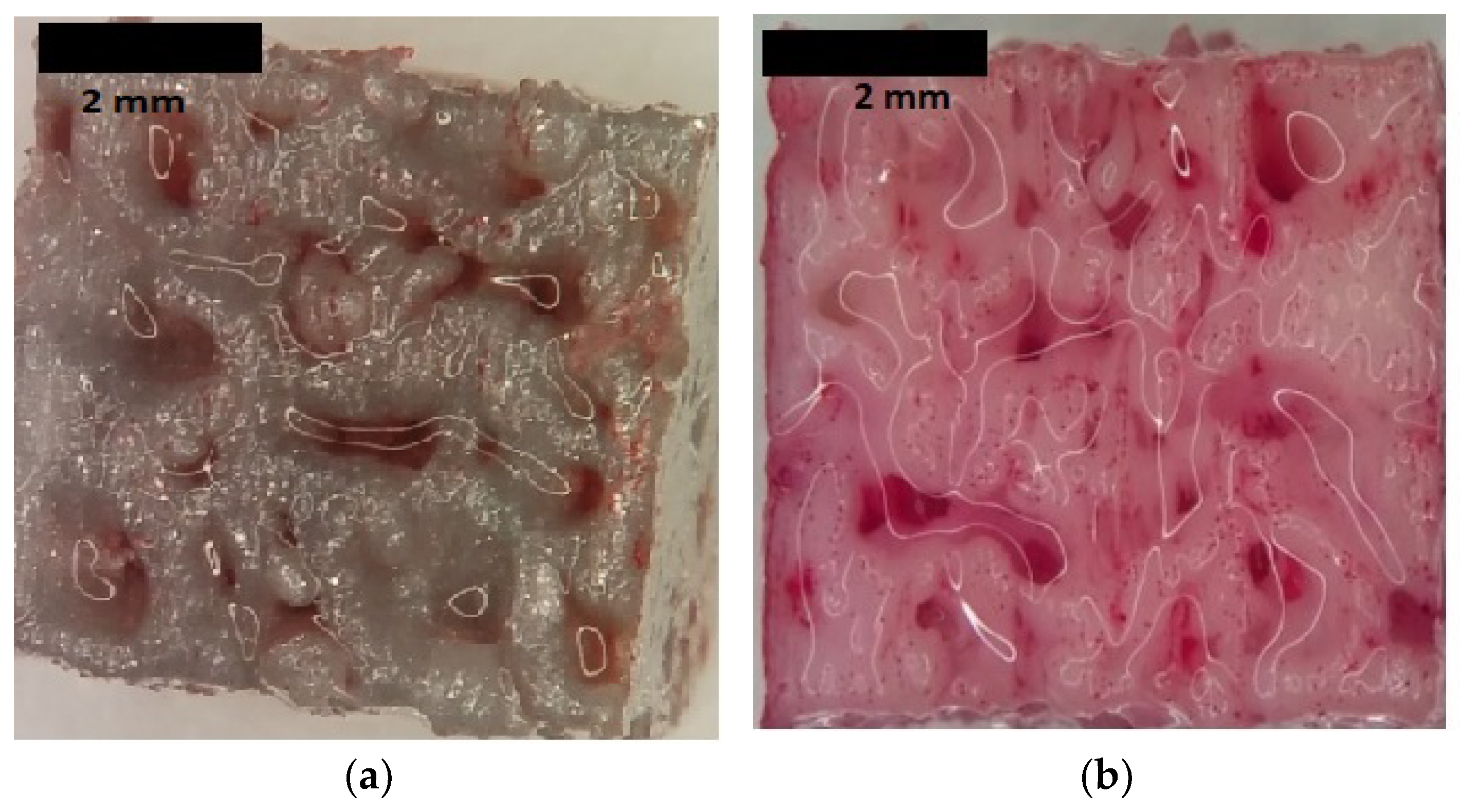
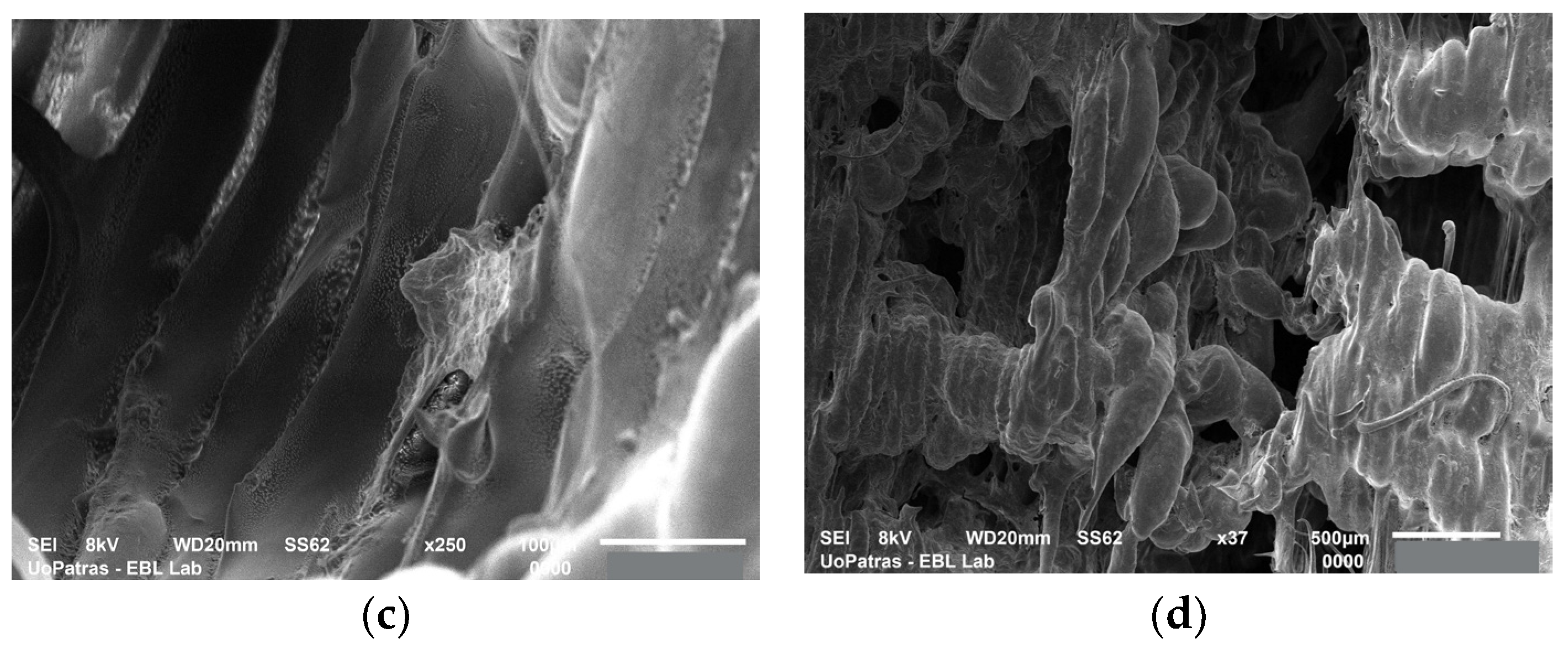
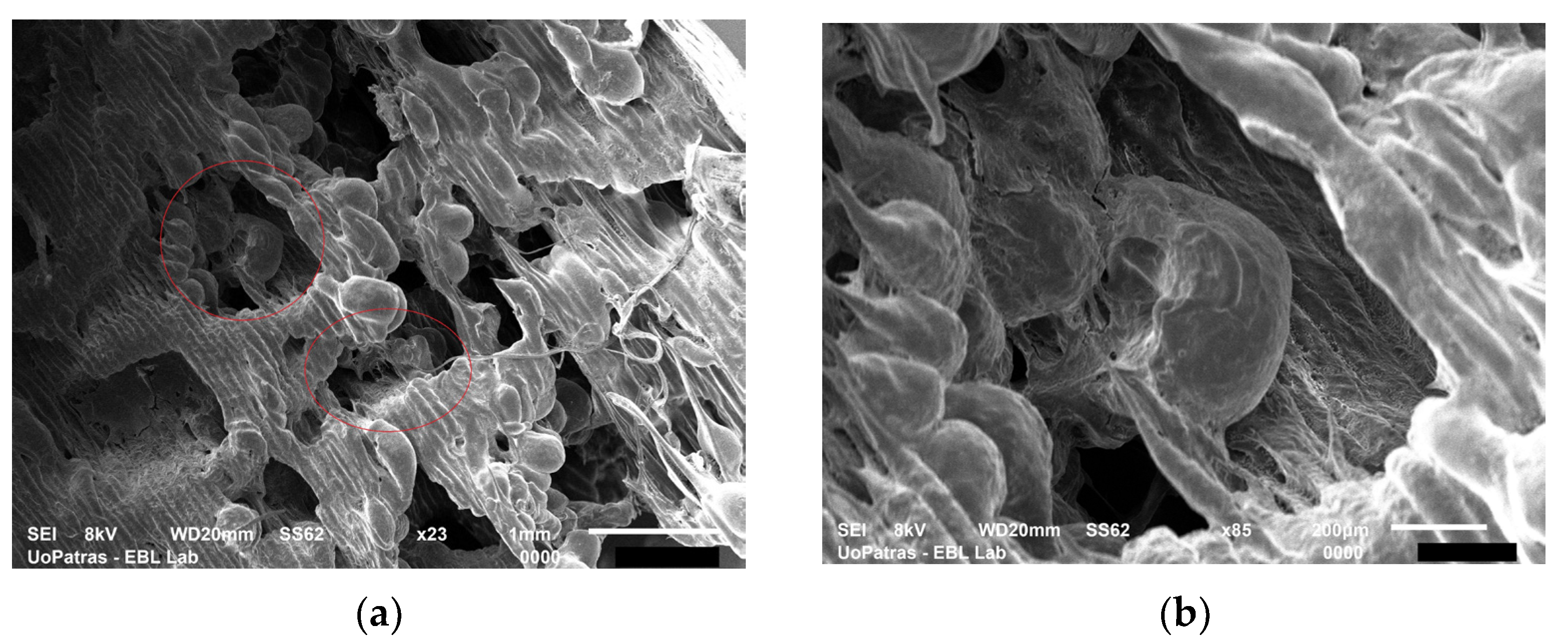
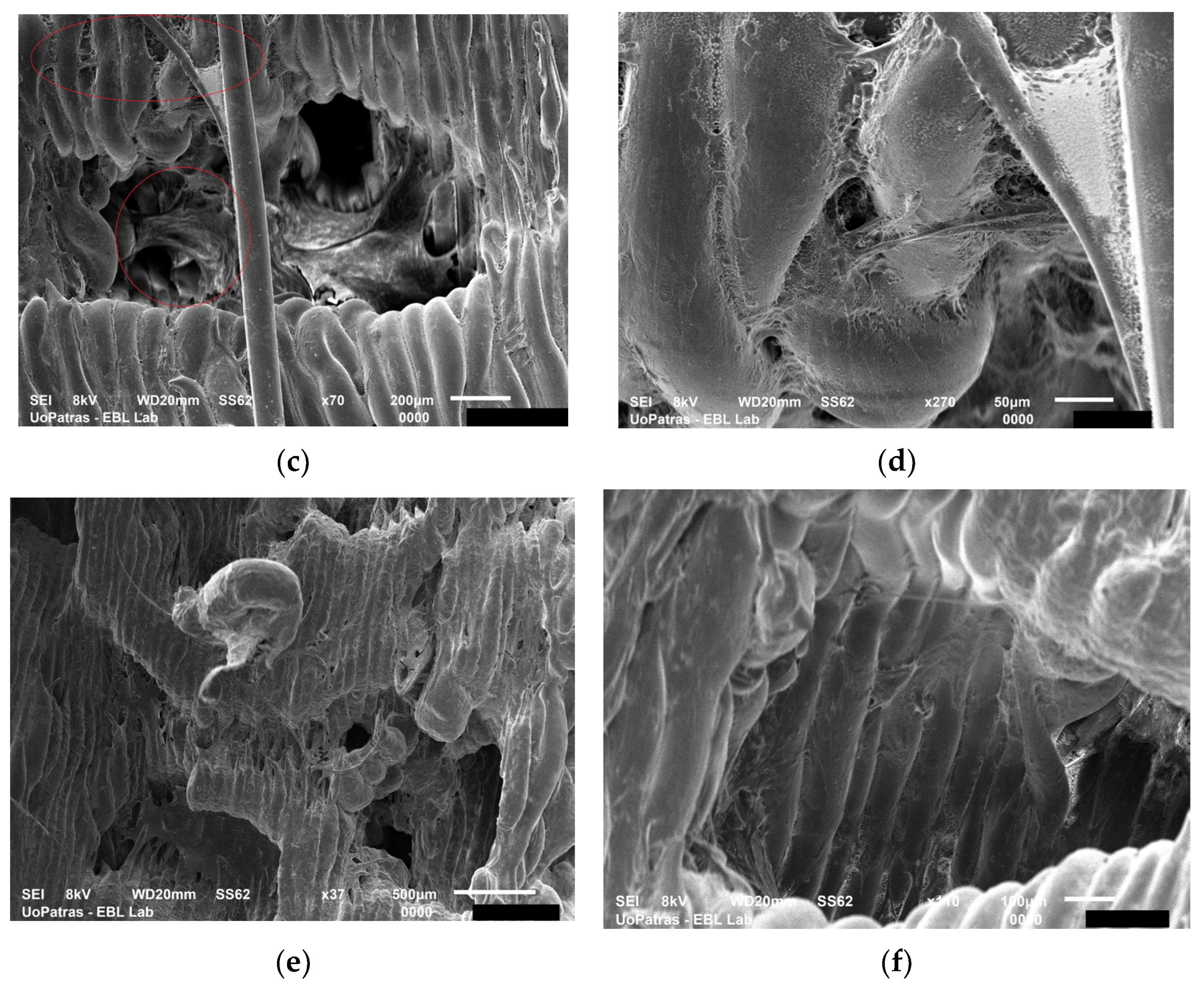
  • Three types of 3D scaffolds were fabricated: CNTs-reinforced PCL by electrospinning, as well as PLA and PU by 3D printing. The electrospun scaffolds were multi-layered. All scaffolds had micro-level pores. The pores of the 3D printed scaffolds were irregularly shaped and biomimetic.
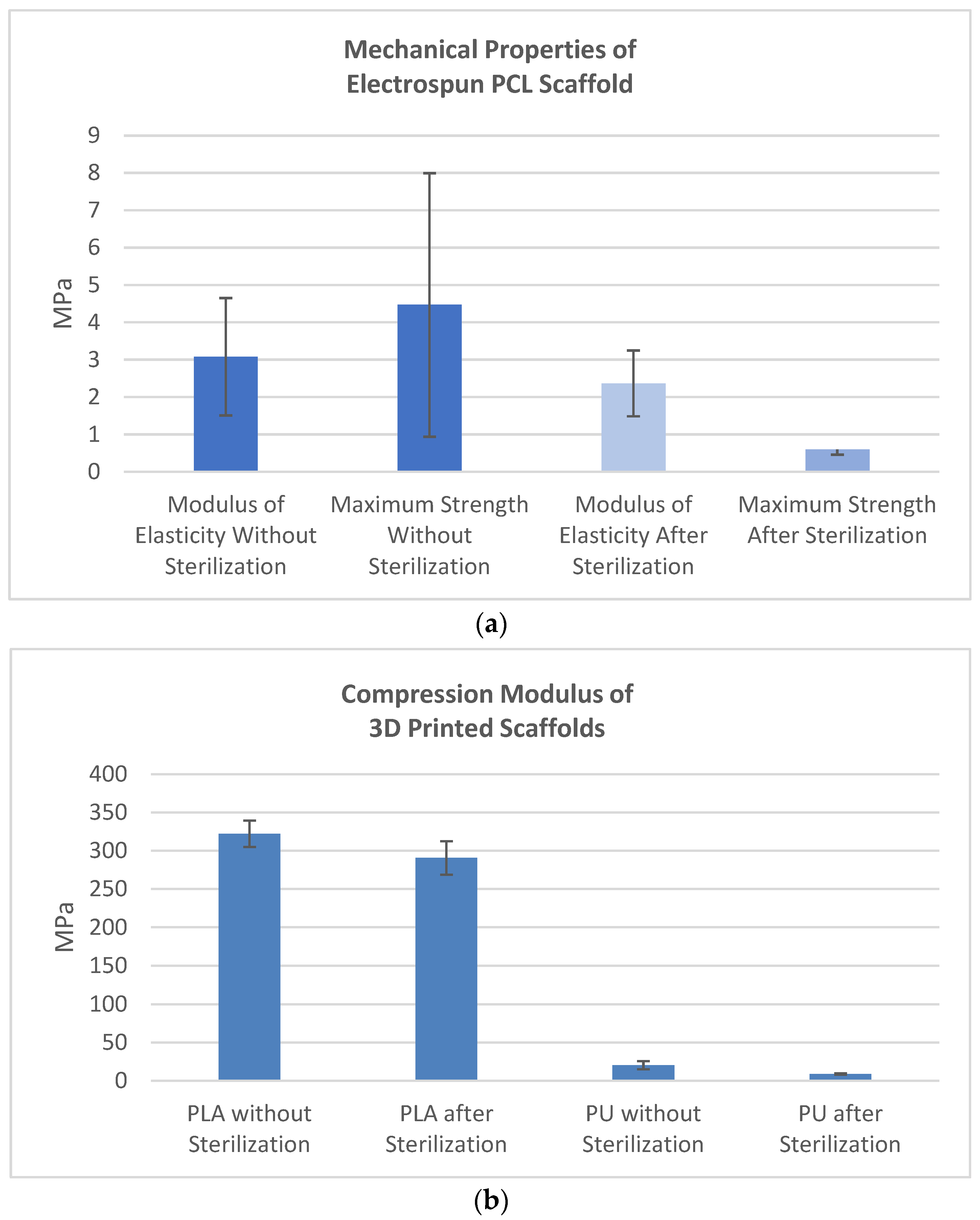
  • The PCL has weak overall mechanical properties, but it performs well in tensile, having a good elasticity modulus. PLA compression modulus of elasticity is considerably higher than the one of PU. The ultimate strength of PCL and PU is almost similar, but PU exhibits a rubber-like behavior while PLA a plastic one. These properties are extremely important to understand cell feedback to scaffolds fabricated from these two types of thermoplastics.
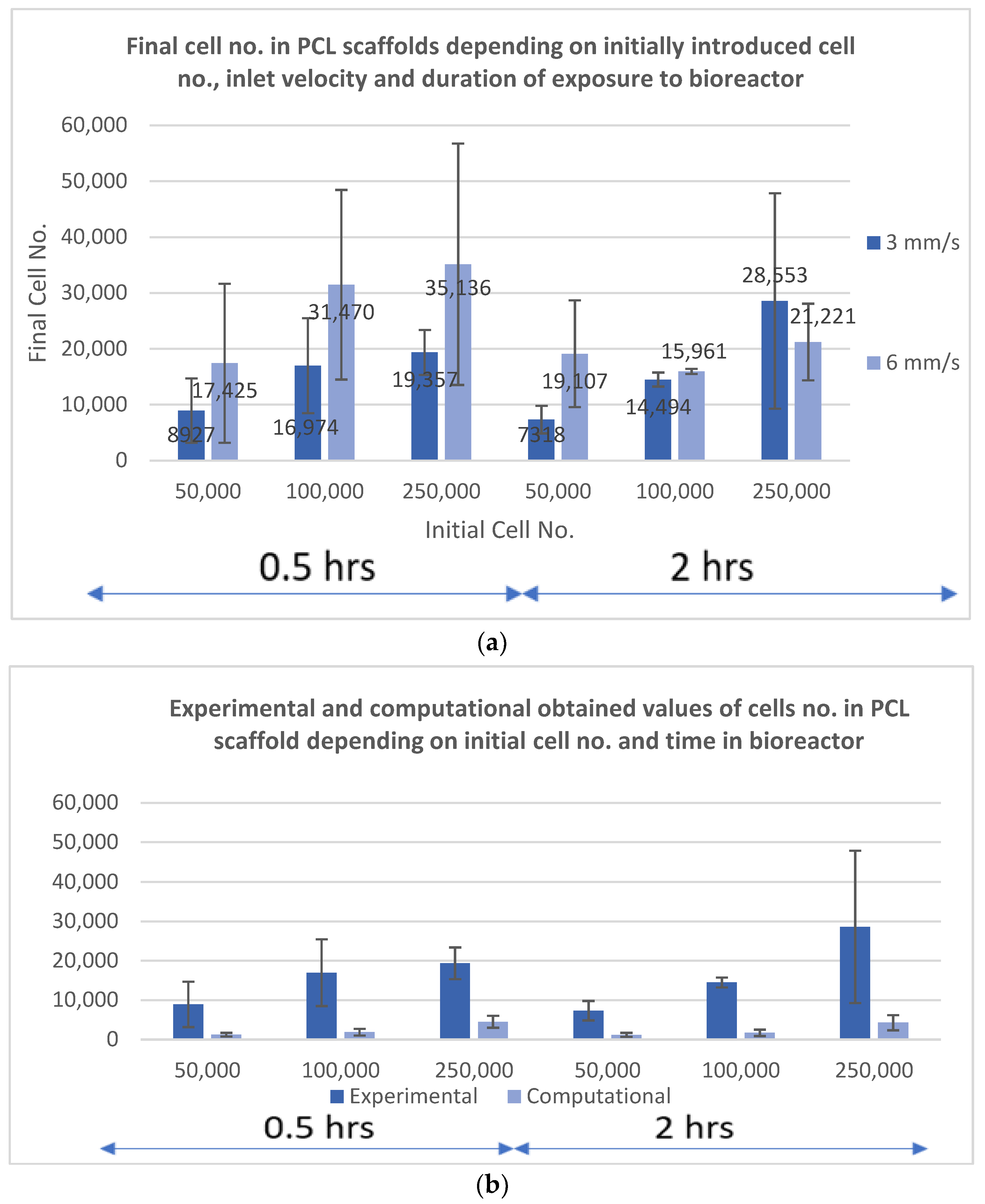
  • The evaluation of the computational study was made with stem cells seeded in PCL electrospun scaffolds; it was shown that the most appropriate inlet velocity was 3 mm/s while the best duration of exposure in a bioreactor was 0.5 h. The procedure consisted in placing the scaffold in the bioreactor and applying a flow of culture medium containing cells, in order to mimic the dynamic micro-environment of the body and how floating cells will end up attaching to the 3D structure. Cells attached in a much higher number than theoretically predicted which indicates the crucial role of biological adhesion in vitro and in vivo.
  • The optimum number of deposited cells depends very much on the material of the scaffold and the duration of the experiment. Short experiments (0.5 to 2 h) may involve 2.5 × 10⁵ cells if the surface area of the 3D structure is at least 1 × 1 cm2. For longer incubation times (1 to 3 days), 105 cells in population is the optimum.
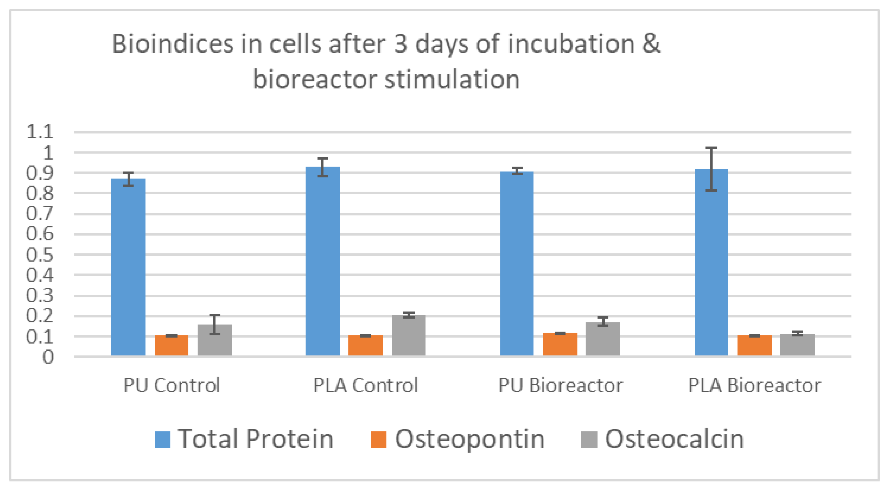
  • The measurements of MTT and Alizarin red indicated that the PU scaffold with rubber-like behavior enabled enhanced feedback with respect to cells viability, followed by intense mineralization. It worth mentioning that PU comparing to PLA has properties closer to the natural tissue. The viability and the mineralization in cells in PLA scaffold were enabled simultaneously and were moderate in intensity comparing to the PU case.

5.3. Highlights

The dynamic stimulation of the cell-loaded scaffolds in the bioreactor has different effect on the cells, depending on the nature of the scaffold material. The most important conclusions of the present research are summarized in Table 3.
On less stiff substrates (e.g., PU in this study), a dynamic flow comparing to the static conditions enables adhesion and several processes are regulated depending on this parameter. The high detected levels of total protein in cells in PU is due to the increased proliferation and a high number of attached cells after the application of the bioreactor. On the other hand, PLA stiff-strong adhesion of cells happens instantly because of the material nature, leading to an increase in the protein content in static conditions. The addition of the dynamic flow with the bioreactor regulates cells adhesion to PU, but it does not significantly influence their state on PLA. Osteopontin levels are boosted up in cells in PU scaffolds through the applied fluid dynamics of the bioreactor, as a result of both good proliferation due to biomimetic material properties and improved adhesion caused by a dynamic micro-environment. Later, osteocalcin levels in cells in PU are regulated and due to confluency, cells go through a process of intense mineralization proven by osteocalcin and Alizarin red levels. The opposite happens with the PLA, where adhesion is strong under static conditions. Cells enter prematurely in a differentiated phase, and they proliferate slowly after longer incubation periods. The application of a dynamic environment does not improve the situation; for PLA, the mineralization of the cells is intense in static conditions and the application of additional stresses reduces all cellular activities. We may globally conclude that there is a turning of situation regarding the faith of cells in physiologic-like environment depending on the material of the scaffold, mainly on its stiffness. Finally, in vitro studies with cell cultures in static conditions partially reflect the reality about cellular behaviors.

Author Contributions

Conceptualization, D.D.D. and D.V.P.; methodology, D.P., F.K.K. and A.E.M.; software, V.K.; validation, D.V.P., F.K.K. and A.E.M.; formal analysis, D.V.P., F.K.K. and V.K.; investigation, F.K.K., A.E.M., P.M. and E.M.; resources, D.P., D.D.D. and V.K.; data curation, F.K.K., A.E.M., P.M. and E.M.; writing—F.K.K. and A.E.M.; writing—review and editing, D.V.P.; visualization, D.D.D. and D.V.P.; supervision, D.D.D. and D.V.P.; project administration, D.D.D. and D.P.; funding acquisition, D.P., D.D.D. and V.K. All authors have read and agreed to the published version of the manuscript.

Funding

This research was funded by the Hellenic Foundation for Research and Innovation (HFRI) under the HRFI–Research grants, Project Acronym: COMPACT, Project no. 2060.

Institutional Review Board Statement

The study was conducted in accordance with the Declaration of Helsinki, and approved by the Institutional Review Board (or Ethics Committee) of the Hellenic Cord Blood Bank (HCBB). All human umbilical cords were accompanied by informed consent, which was in accordance with the declaration of Helsinki and conformed with the ethical standards of the Greek National Ethical Committee. The informed consent was provided by the mothers, few days before the delivery. The overall study has received approval from the Hellenic Cord Blood Bank, Biomedical Research Foundation Academy of Athens ethical board (Reference No. 1754, 21 January 2021).

Data Availability Statement

All data are available upon request from the authors.

Acknowledgments

To the team of Advanced Light Microscopy Facility of the Medical School at the University of Patras, for support with the confocal imaging.

Conflicts of Interest

The authors declare no conflict of interest.

References

  1. Hutmacher, D.W.; Singh, H. Computational fluid dynamics for improved bioreactor design and 3D culture. Trends Biotechnol. 2008, 26, 166–172. [Google Scholar] [CrossRef] [PubMed]
  2. Singh, H.; Hutmacher, D.W. Bioreactor Studies and Computational Fluid Dynamics. In Bioreactor Systems for Tissue Engineering; Kasper, C., van Griensven, M., Pörtner, R., Eds.; Springer: Berlin/Heidelberg, Germany, 2009; pp. 231–249. [Google Scholar]
  3. Guller, A.; Igrunkova, A. Engineered Microenvironments for 3D Cell Culture and Regenerative Medicine: Challenges, Advances, and Trends. Bioengineering 2023, 10, 17. [Google Scholar] [CrossRef] [PubMed]
  4. Nikolova, M.P.; Chavali, M.S. Recent advances in biomaterials for 3D scaffolds: A review. Bioact. Mater. 2019, 4, 271–292. [Google Scholar] [CrossRef]
  5. Sampson, K.; Koo, S.; Gadola, C.; Vasiukhina, A.; Singh, A.; Spartano, A.; Gollapudi, R.; Duley, M.; Mueller, J.; James, P.F.; et al. Cultivation of hierarchical 3D scaffolds inside a perfusion bioreactor: Scaffold design and finite-element analysis of fluid flow. SN Appl. Sci. 2021, 3, 884. [Google Scholar] [CrossRef]
  6. Wang, Z.; Wang, Y.; Yan, J.; Zhang, K.; Lin, F.; Xiang, L.; Deng, L.; Guan, Z.; Cui, W.; Zhang, H. Pharmaceutical electrospinning and 3D printing scaffold design for bone regeneration. Adv. Drug Deliv. Rev. 2021, 174, 504–534. [Google Scholar] [CrossRef] [PubMed]
  7. Chia, H.N.; Wu, B.M. Recent advances in 3D printing of biomaterials. J. Biol. Eng. 2015, 9, 4. [Google Scholar] [CrossRef]
  8. Alam, F.; Shukla, V.R.; Varadarajan, K.; Kumar, S. Microarchitected 3D printed polylactic acid (PLA) nanocomposite scaffolds for biomedical applications. J. Mech. Behav. Biomed. Mater. 2020, 103, 103576. [Google Scholar] [CrossRef]
  9. Bruyas, A.; Lou, F.; Stahl, A.M.; Gardner, M.; Maloney, W.; Goodman, S.; Yang, Y.P. Systematic characterization of 3D-printed PCL/β-TCP scaffolds for biomedical devices and bone tissue engineering: Influence of composition and porosity. J. Mater. Res. 2018, 33, 1948–1959. [Google Scholar] [CrossRef]
  10. Hu, X.; Zhao, W.; Zhang, Z.; Xie, J.; He, J.; Cao, J.; Li, Q.; Yan, Y.; Xiong, C.; Li, K. Novel 3D printed shape-memory PLLA-TMC/GA-TMC scaffolds for bone tissue engineering with the improved mechanical properties and degradability. Chin. Chem. Lett. 2023, 34, 107451. [Google Scholar] [CrossRef]
  11. Nair, A.; Tang, L. Influence of scaffold design on host immune and stem cell responses. Semin. Immunol. 2017, 29, 62–71. [Google Scholar] [CrossRef]
  12. Florczyk, S.J.; Hotaling, N.A.; Simon, M.; Chalfoun, J.; Horenberg, A.L.; Schaub, N.J.; Wang, D.; Szczypiński, P.M.; DeFelice, V.L.; Bajcsy, P.; et al. Measuring dimensionality of cell-scaffold contacts of primary human bone marrow stromal cells cultured on electrospun fiber scaffolds. J. Biomed. Mater. Res. Part A 2023, 111, 106–117. [Google Scholar] [CrossRef]
  13. Thomas, V.; Jose, M.V.; Chowdhury, S.; Sullivan, J.F.; Dean, D.R.; Vohra, Y.K. Mechano-morphological studies of aligned nanofibrous scaffolds of polycaprolactone fabricated by electrospinning. J. Biomater. Sci. Polym. Ed. 2006, 17, 969–984. [Google Scholar] [CrossRef] [PubMed]
  14. Suwantong, O. Biomedical applications of electrospun polycaprolactone fiber mats. Polym. Adv. Technol. 2016, 27, 1264–1273. [Google Scholar] [CrossRef]
  15. Wang, P.; Pyo, S.-H.; Zhu, W.; Hwang, H.; Chen, S. 3D Printing of Polyurethanes for Biomedical Applications, in Emerging Technologies in Biophysical Sciences: A World Scientific Reference. In Emerging Technologies in Biophysical Sciences: A World Scientific Reference; World Scientific: Singapore, 2020; pp. 389–406. [Google Scholar] [CrossRef]
  16. Rusu, L.-C.; Ardelean, L.C.; Jitariu, A.-A.; Miu, C.A.; Streian, C.G. An Insight into the Structural Diversity and Clinical Applicability of Polyurethanes in Biomedicine. Polymers 2020, 12, 1197. [Google Scholar] [CrossRef] [PubMed]
  17. Chen, X.; Chen, G.; Wang, G.; Zhu, P.; Gao, C. Recent Progress on 3D-Printed Polylactic Acid and Its Applications in Bone Repair. Adv. Eng. Mater. 2020, 22, 1901065. [Google Scholar] [CrossRef]
  18. Elamparithi, A.; Punnoose, A.M.; Kuruvilla, S.; Ravi, M.; Rao, S.; Paul, S.F.D. Electrospun polycaprolactone matrices with tensile properties suitable for soft tissue engineering. Artif. Cells Nanomed. Biotechnol. 2016, 44, 878–884. [Google Scholar] [CrossRef]
  19. Hou, Y.; Wang, W.; Bartolo, P. Investigation of polycaprolactone for bone tissue engineering scaffolds: In vitro degradation and biological studies. Mater. Des. 2022, 216, 110582. [Google Scholar] [CrossRef]
  20. Kanyanta, V.; Ivankovic, A. Mechanical characterisation of polyurethane elastomer for biomedical applications. J. Mech. Behav. Biomed. Mater. 2010, 3, 51–62. [Google Scholar] [CrossRef]
  21. Kucinska-Lipka, J.; Gubanska, I.; Sienkiewicz, M. Thermal and mechanical properties of polyurethanes modified with L-ascorbic acid. J. Therm. Anal. Calorim. 2017, 127, 1631–1638. [Google Scholar] [CrossRef]
  22. Wendels, S.; Avérous, L. Biobased polyurethanes for biomedical applications. Bioact. Mater. 2021, 6, 1083–1106. [Google Scholar] [CrossRef]
  23. Pinto, V.C.; Ramos, T.; Alves, S.; Xavier, J.; Tavares, P.; Moreira, P.; Guedes, R.M. Comparative Failure Analysis of PLA, PLA/GNP and PLA/CNT-COOH Biodegradable Nanocomposites thin Films. Procedia Eng. 2015, 114, 635–642. [Google Scholar] [CrossRef]
  24. Mei, H.; Yin, X.; Zhang, J.; Zhao, W. Compressive Properties of 3D Printed Polylactic Acid Matrix Composites Reinforced by Short Fibers and SiC Nanowires. Adv. Eng. Mater. 2019, 21, 1800539. [Google Scholar] [CrossRef]
  25. Stefan, S.; Schirmer, C.; Maschke, R.W.; Rossi, L.; Eibl, R.; Eibl, D. Computational Fluid Dynamics for Advanced Characterisation of Bioreactors Used in the Biopharmaceutical Industry: Part I: Literature Review. In Computational Fluid Dynamics—Recent Advances, New Perspectives and Applications; Guozhao, J., Jingliang, D., Eds.; IntechOpen: Rijeka, Croatia, 2023; Chapter 2. [Google Scholar]
  26. Meneses, J.; Silva, J.C.; Fernandes, S.R.; Datta, A.; Ferreira, F.C.; Moura, C.; Amado, S.; Alves, N.; Pascoal-Faria, P. A Multimodal Stimulation Cell Culture Bioreactor for Tissue Engineering: A Numerical Modelling Approach. Polymers 2020, 12, 940. [Google Scholar] [CrossRef] [PubMed]
  27. Choe, R.; Devoy, E.; Kuzemchak, B.; Sherry, M.; Jabari, E.; Packer, J.D.; Fisher, J.P. Computational investigation of interface printing patterns within 3D printed multilayered scaffolds for osteochondral tissue engineering. Biofabrication 2022, 14, 025015. [Google Scholar] [CrossRef] [PubMed]
  28. Kozaniti, F.K.; Deligianni, D.D.; Georgiou, M.D.; Portan, D.V. The Role of Substrate Topography and Stiffness on MSC Cells Functions: Key Material Properties for Biomimetic Bone Tissue Engineering. Biomimetics 2022, 7, 7. [Google Scholar] [CrossRef] [PubMed]
  29. Song, J.; Zhu, G.; Wang, L.; An, G.; Shi, X.; Wang, Y. Assembling of electrospun meshes into three-dimensional porous scaffolds for bone repair. Biofabrication 2017, 9, 015018. [Google Scholar] [CrossRef]
  30. ASTM F2150-02; Standard Guide for Characterization and Testing of Biomaterial Scaffolds Used in Regenerative Medicine and Tissue-Engineered Medical Products. ASTM International: West Conshohocken, PA, USA, 2002.
  31. ASTM D882-18; Standard Test Method for Tensile Properties of Thin Plastic Sheeting. ASTM International: West Conshohocken, PA, USA, 2002.
  32. Bušs, A.; Suleiko, A.; Rugele, K.; Vanags, J. CFD Analysis of a Stirred Vessel Bioreactor with Double Pitch Blade and Rushton Type Impellers. In Proceedings of the 2017 COMSOL Conference, Rotterdam, the Netherlands, 18 October 2017. [Google Scholar]
  33. Chatzistamatiou, T.K.; Papassavas, A.C.; Michalopoulos, E.; Gamaloutsos, C.; Mallis, P.; Gontika, I.; Panagouli, E.; Koussoulakos, S.L.; Stavropoulos-Giokas, C. Optimizing isolation culture and freezing methods to preserve Wharton’s jelly’s mesenchymal stem cell (MSC) properties: An MSC banking protocol validation for the Hellenic Cord Blood Bank. Transfusion 2014, 54, 3108–3120. [Google Scholar] [CrossRef]
  34. Gregory, C.A.; Gunn, W.G.; Peister, A.; Prockop, D.J. An Alizarin red-based assay of mineralization by adherent cells in culture: Comparison with cetylpyridinium chloride extraction. Anal. Biochem. 2004, 329, 77–84. [Google Scholar] [CrossRef]
  35. Wilson, C.; Clegg, R.E.; Leavesley, D.I.; Pearcy, M.J. Mediation of Biomaterial–Cell Interactions by Adsorbed Proteins: A Review. Tissue Eng. 2005, 11, 1–18. [Google Scholar] [CrossRef]
  36. Sikavitsas, V.; Bancroft, G.N.; Holtorf, H.L.; Jansen, J.A.; Mikos, A.G. Mineralized matrix deposition by marrow stromal osteoblasts in 3D perfusion culture increases with increasing fluid shear forces. Proc. Natl. Acad. Sci. USA 2004, 100, 14683–14688. [Google Scholar] [CrossRef]
  37. Pawluchin, A.; Galic, M. Moving through a changing world: Single cell migration in 2D vs. 3D. Front. Cell Dev. Biol. 2022, 10, 1080995. [Google Scholar] [CrossRef] [PubMed]
  38. Crétel, E.; Pierres, A.; Benoliel, A.-M.; Bongrand, P. How Cells Feel Their Environment: A Focus on Early Dynamic Events. Cell. Mol. Bioeng. 2008, 1, 5–14. [Google Scholar] [CrossRef] [PubMed]
  39. Bhattacharya, A.; Agarwal, M.; Mukherjee, R.; Sen, P.; Sinha, D.K. 3D micro-environment regulates NF-κβ dependent adhesion to induce monocyte differentiation. Cell Death Dis. 2018, 9, 914. [Google Scholar] [CrossRef]
  40. Cámara-Torres, M.; Sinha, R.; Mota, C.; Moroni, L. Improving cell distribution on 3D additive manufactured scaffolds through engineered seeding media density and viscosity. Acta Biomater. 2020, 101, 183–195. [Google Scholar] [CrossRef] [PubMed]
  41. Feier, A.; Manu, D.R.; Strnad, G.; Dobreanu, M.; Russu, O.M.; Portan, D.; Bataga, T. A Step Forward Standardization of Biocompatibility Testing on Tissue Culture Polystyrene. Mater. Plast. 2018, 55, 303–307. [Google Scholar] [CrossRef]
  42. Portan, D.V.; Kroustalli, A.A.; Deligianni, D.D.; Papanicolaou, G.C. On the biocompatibility between TiO2 nanotubes layer and human osteoblasts. J. Biomed. Mater. Res. Part A 2012, 100, 2546–2553. [Google Scholar] [CrossRef]
  43. Hendriks, M.; Ramasamy, S.K. Blood Vessels and Vascular Niches in Bone Development and Physiological Remodeling. Front. Cell Dev. Biol. 2020, 8, 602278. [Google Scholar] [CrossRef]
  44. Fritton, S.P.; Weinbaum, S. Fluid and Solute Transport in Bone: Flow-Induced Mechanotransduction. Annu. Rev. Fluid Mech. 2008, 41, 347–374. [Google Scholar] [CrossRef]
  45. Lee, S.J.; Oh, S.H.; Liu, J.; Soker, S.; Atala, A.; Yoo, J.J. The use of thermal treatments to enhance the mechanical properties of electrospun poly(ɛ-caprolactone) scaffolds. Biomaterials 2008, 29, 1422–1430. [Google Scholar] [CrossRef]
  46. Lu, L.; Zhang, Q.; Wootton, D.M.; Chiou, R.; Li, D.; Lu, B.; Lelkes, P.I.; Zhou, J. Mechanical Study of Polycaprolactone-hydroxyapatite Porous Scaffolds Created by Porogen-based Solid Freeform Fabrication Method. J. Appl. Biomater. Funct. Mater. 2014, 12, 145–154. [Google Scholar] [CrossRef]
  47. Marolt, D.; Campos, I.M.; Bhumiratana, S.; Koren, A.; Petridis, P.; Zhang, G.; Spitalnik, P.F.; Grayson, W.L.; Vunjak-Novakovic, G. Engineering bone tissue from human embryonic stem cells. Proc. Natl. Acad. Sci. USA 2012, 109, 8705–8709. [Google Scholar] [CrossRef] [PubMed]
Figure 1. Mechanical properties of the three thermoplastic materials used in the present investigation. (a) Tensile Strength, (b) compressive Strength, and (c) modulus of PCL—polycaprolactone, PU—polyurethane and PLA—polylactic acid [18,19,20,21,22,23,24].
Applbiosci 02 00018 g001
Figure 2. (a) An actual picture and (b) a conceptual view of the experimental setup of the home-made bioreactor system—Dynamic Culture.
Applbiosci 02 00018 g002
Figure 3. Comsol-generated graphs: (a) Programmed structure of the 3D scaffolds; (b) 3D image of a scaffold in the bioreactor tube; (c) Cells’ distribution for on scaffold fiber in xz plane, 2.5 × 10⁵ particles, 3 mm/s velocity, 30 min stimulation; (d) Cells’ distribution for on scaffold fiber in yz plane, 2.5 × 10⁵ particles, 3 mm/s velocity, 30 min stimulation.
Applbiosci 02 00018 g003aApplbiosci 02 00018 g003b
Figure 4. Predicted number of cells in the scaffold after several periods of exposure (from 20 to 140 min) and at different inlet velocities.
Applbiosci 02 00018 g004
Figure 5. Cells distribution in the layers vs. inlet velocity and depending on the initial cell number: (a) 5 × 10⁴–50 k; (b) 105–100 k; (c) 2.5 × 10⁵–250 k.
Applbiosci 02 00018 g005aApplbiosci 02 00018 g005b
Figure 6. Cell attachment depending on initial cell number and the inlet velocity.
Applbiosci 02 00018 g006
Figure 7. Samples texture: (a) Electrospun scaffolds texture; (b) Electrospun scaffolds dimensions; (c) Cubic PU—(right) side and PLA—(left) side scaffolds, and (d) SEM image of CNTs-reinforced PCL.
Applbiosci 02 00018 g007
Figure 8. Mechanical properties of scaffolds: (a) Values of the elasticity modulus and maximum strength of electrospinning materials; (b) Compression modulus of PLA and PU Scaffolds before and after sterilization.
Applbiosci 02 00018 g008
Figure 9. (a) The measured number of cells in PCL scaffolds depending on the initial cell number, the inlet velocity, and the duration of the exposure; and (b) Experimental vs. predicted results of cells in scaffold depending on initial cell no. and exposure duration to the bioreactor.
Applbiosci 02 00018 g009
Figure 10. Experiments with stem cells: (a) MTT viability in PLA scaffolds—experimental vs. predicted results, and (b) Viability measurement with Results of MMT and Alizarin red assay for cells deposited in 3D printed PLA and PU scaffolds and maintained in bioreactor.
Applbiosci 02 00018 g010
Figure 11. (a) PLA scaffold—Alizarin staining after 3 days incubation and bioreactor stimulation—3 mm/s velocity, 105 cells, 0.5 h; (b) PU scaffold—Alizarin staining after 3 days incubation and bioreactor stimulation—3 mm/s velocity, 105 cells, 0.5 h; (c) SEM image of cells in PLA; and (d) SEM image of cells in PU.
Applbiosci 02 00018 g011aApplbiosci 02 00018 g011b
Figure 12. Levels of TP, OPN, and OC in cells in scaffolds under static conditions (polyurethane control and PLA control) and after dynamic stimulation in the bioreactor (polyurethane bioreactor and PLA bioreactor).
Applbiosci 02 00018 g012
Figure 13. SEM images of cells developing in the scaffolds: (a) PU scaffold before exposure to bioreactor at low magnification; (b) PU scaffolds before exposure to bioreactor at increased magnification; (c) PLA scaffold before exposure to bioreactor at low magnification; (d) PLA scaffold before exposure to bioreactor at increased magnification; (e) PU scaffold after exposure to bioreactor; (f) PLA scaffold after exposure to bioreactor.
Applbiosci 02 00018 g013aApplbiosci 02 00018 g013b
Figure 14. Actin staining and confocal imaging of cells in: (a) PLA scaffold, (b,c) PU scaffold.
Applbiosci 02 00018 g014aApplbiosci 02 00018 g014b
Table 1. Key parameters in the Comsol simulation.
Inlet Velocity (mm/s)
136
Particles no.5 × 104301203012030120
105301203012030120
2.5 × 105301203012030120
Stimulation duration (min)
Table 2. Values of TP, OPN, and OC in cells in the two types of scaffolds, with and without exposure to bioreactor.
Scaffold TypeTotal ProteinOsteopontinOsteocalcin
PU Control 10.870.1060.158
PLA Control0.930.1050.205
PU Bioreactor 20.9090.1160.172
PLA Bioreactor0.930.1050.114
1 Scaffolds with cells were the control samples, incubated in static conditions 2 Scaffolds with cells were subjected to bioreactor conditions.
Table 3. Conclusions related to cells feedback to the scaffold property and the bioreactor.
Cells Feedback in a Static Experiment
Biomarker/MaterialPU (polyurethane)PLA (polylactic acid)
Total Protein (depends on substrate stiffness)Moderate due to weak adhesion.Pronounced due to strong adhesion.
Osteopontin (depends of cells no. and quality of adhesion)Regulated by development of extracellular matrix due to increased proliferation of cells. Regulated by development of extracellular matrix due to strong adhesion of cells.
Osteocalcin (depends on differentiation)Moderate due to weak differentiation.Pronounced due to strong differentiation.
Cells Feedback in a Dynamic Experiment with Bioreactor
Biomarker/MaterialPU (polyurethane)PLA (polylactic acid)
MTT ViabilityHigh cell no. because of biomimetic material properties.Low cell no. because of high stiffness
Alizarin redMineralization is induced due to confluency of cells in scaffold.Mineralization has been induced in static conditions due to the strong adhesion.
Total Protein (level has been adjusted during static conditions)Stays steady comparing to static conditions.Stays steady comparing to static conditions.
OsteopontinConsiderably increased level due to introduction of stresses through fluid flow.No significant change comparing to static experiment.
OsteocalcinMineralization is induced due to confluency of cells in scaffold.Mineralization has been induced in static conditions due to the strong adhesion.
Disclaimer/Publisher’s Note: The statements, opinions and data contained in all publications are solely those of the individual author(s) and contributor(s) and not of MDPI and/or the editor(s). MDPI and/or the editor(s) disclaim responsibility for any injury to people or property resulting from any ideas, methods, instructions or products referred to in the content.

