Article

Extension of Quasi-Load Insensitive Generalized Class-E Doherty Operation with Complex Load Trajectories

1
University Grenoble Alpes, EEATS, CEA-LETI, 38054 Grenoble, France
2
University Grenoble Alpes, CNRS, Grenoble INP, TIMA, 38000 Grenoble, France
*
Authors to whom correspondence should be addressed.
Chips 2025, 4(2), 26; https://doi.org/10.3390/chips4020026
Submission received: 28 March 2025 / Revised: 29 April 2025 / Accepted: 30 April 2025 / Published: 13 May 2025
(This article belongs to the Special Issue New Research in Microelectronics and Electronics)

Abstract

:
This paper extends the quasi-load insensitive (QLI) Class-E Doherty power amplifier (PA) design methodology to address Doherty PA combiners with complex load impedance trajectories. Additionally, the QLI operation is analyzed for generalized class-E output matching networks with input series inductors and finite DC-feed inductors. We demonstrate that the QLI class-E Doherty operation can be achieved for various Doherty combiners by selecting the appropriate combination of class-E outputs matching network resonance factors and input series inductances. Moreover, a modified class-E output network is proposed to overcome the frequency limitation that might be caused by the class-E network resonance factor choice. To validate the proposed methodology, two 40 W Doherty PAs are designed and simulated using commercial GaN HEMT transistors achieving more than 70% efficiency over a 6 dB output power back-off at 3.8 GHz.

1. Introduction

Modern wireless communication systems use complex modulated signals with high instantaneous bandwidth to improve spectral efficiency and data rate. These signals exhibit a high peak-to-average power ratio (PAPR) which requires high back-off from the saturation power to meet the system linearity requirement, consequently degrading the average efficiency of conventional PAs. In addition, 5G transceivers need to address the challenge of an increased number of frequency bands strengthening the efficiency–bandwidth trade-off in 5G PAs [1].
To increase the PA efficiency under high output power back-off (OBO), supply modulation (Envelop Tracking) and load modulation (Doherty, Outphasing …) PA architectures have been developed [1,2,3]. For cellular wireless infrastructure applications, the wide adoption of conventional Doherty PA (DPA) gave birth to several variants and design approaches enabling increased OBO range [4], extended operating bandwidth [5,6,7] and compact size [8]. The QLI class-E DPA proposed in [6] shows promising efficiency and bandwidth performance. However, the analysis proposed in [6] only considers DPA combiners with pure-real load impedance trajectories. This limits the design space of such promising methodology, while modern DPA designs rely on combiners with non-real impedance trajectories [3,8].
In this paper, the QLI class-E DPA design methodology is extended to enable QLI operation for Doherty combiners with complex load impedance trajectories. Section 2 reviews the class-E PA operation principle with a focus on generalized class-E output matching network parameters calculation. Section 3 introduces the original QLI class-E DPA design methodology and presents an extension of the QLI methodology for generalized class-E networks with input series inductors and finite DC-feed inductors. The extended methodology allows us to achieve QLI operations for compact Doherty combiners with complex load impedance trajectories, which is not directly feasible in the original QLI methodology. Furthermore, the maximum operating frequency is discussed, and a modified class-E network configuration is proposed to overcome the maximum operating frequency limitation that might be caused by the choice of the class-E network resonance factor and input series inductor. Finally, Section 4 presents the simulated performances of two 40 W class-E Doherty PAs designed using the proposed methodology.

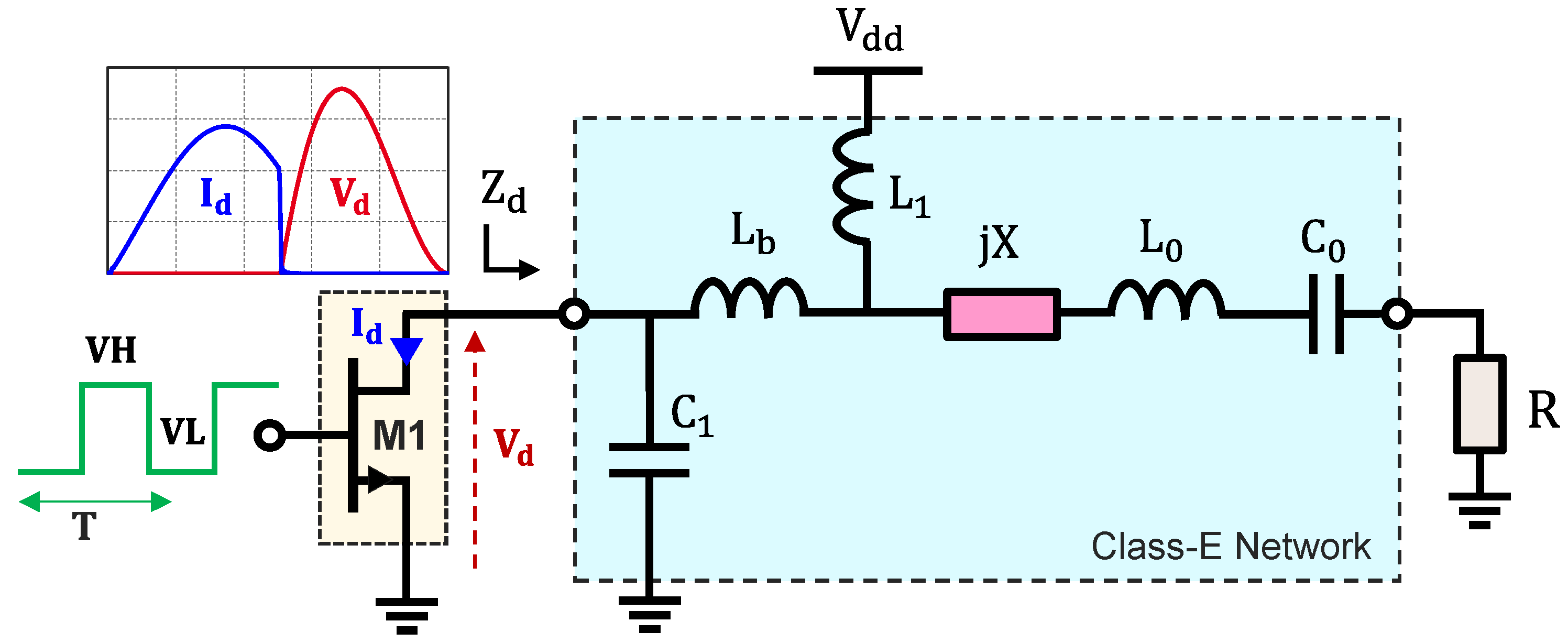
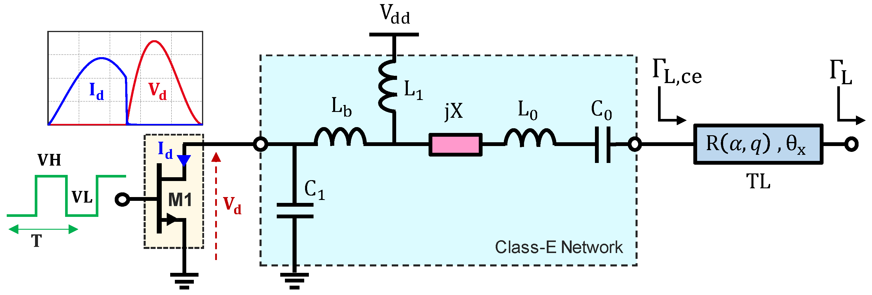
2. Generalized Class-E Output Network

The generalized form of the single-ended Class-E PA output matching network, depicted in Figure 1, includes an input series inductance L b and a finite DC-feed inductor L 1 [9]. The inductor L 1 provides the DC current to the device during the on-state and contributes along with the shunt capacitance C 1 to ensure the AC current flows to the output during the off-state. The series reactance j X adjusts the initial phase-shift of the output current to avoid the current and voltage overlapping at the device drain. Finally, the L 0 C 0 resonator is used to filter out the harmonics and to achieve a pure sinusoidal output current through the load R .
The analytical solution of the generalized class-E network is given in [9] considering a square input drive signal with 50% duty cycle. The network elements { C 1 , L b , L 1 , X , L 0 , C 0 , R } , given in (1)–(6), are expressed in terms of the target output power   P o u t , the supply voltage   V d d , the angular design frequency   ω 0 , the loaded quality-factor Q L of the harmonic filter   L 0 C 0 and the so-called K-set coefficients   K P , K L , K C , K X . The K-set coefficients depend on the free design parameters   { α , q } where α = L b / L 1   and the resonance factor   q = 1 /   ( ω 0 L 1 C 1 ) .
R ( α , q ) = K P ( α , q )   V d d 2 P o u t
X ( α , q ) = K x ( α , q )   R ( α , q ) ω 0
L 0 ( α , q ) = Q L R ( α , q ) ω 0
C 0 ( α , q ) = 1 L 0 ( α , q )   ω 0 2
L 1 ( α , q ) = K L ( α , q )   R ( α , q ) ω 0
C 1 ( α , q ) = K c ( α , q )   ω 0   R ( α , q )
The coefficients K L , K C , K x and K P are plotted in Figure 2 versus q and for different values of α . Note that Equations (A1) and (A2) from [9] in Appendix A required to plot the K-set coefficients have typo errors. The corrected version is given in Appendix A.
It is important to mention that for     Q L 1 ,   α 0 ,   q < 2 , the class-E network presents the same drain plane impedance Z d at fundamental and harmonic frequencies (7). Note that for q > 2 , the analytical equations from [9] are not valid, and the class-E waveforms are no longer achieved.
Z d ( n f 0 ) 0.88 + j   0.63 × V d d 2 / P o u t               n = 1   j   3.174   V d d 2 / ( n × P o u t )                       n > 1
In the following, the original (Quasi-Load Insensitive) QLI Class-E Doherty Operation proposed in [6,7] is introduced. Then, the QLI design methodology is extended using the generalized class-E analytical solution proposed in [9] in order to enable QLI operation for non-conventional Doherty combiners. As otherwise mentioned, all simulations are obtained using large signal simulations and ideally large signal switch models.

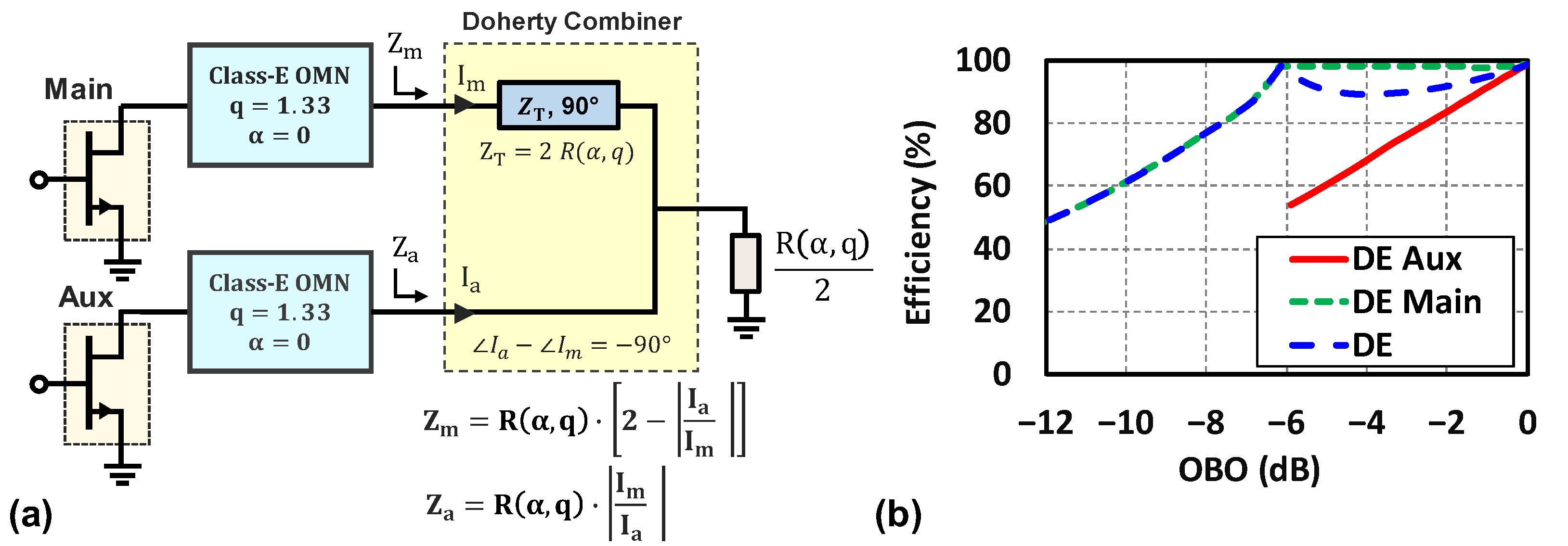
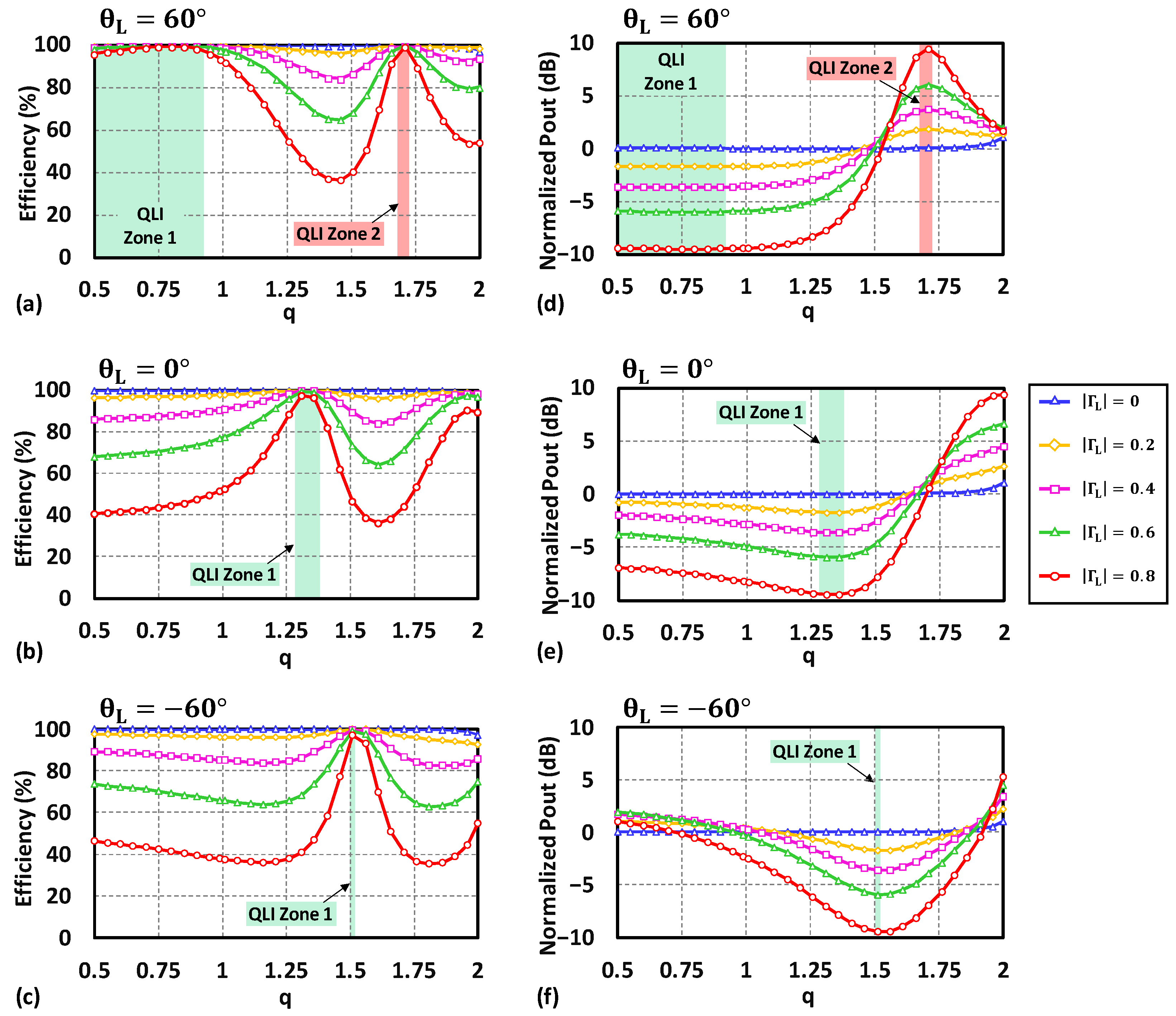
3. Quasi-Load Insensitive Class-E Doherty Operation

3.1. Original QLI Class-E ( q = 1.33 and   α = 0 ) DPA Design Methodology

The original QLI class-E Doherty design methodology, presented in [6,7], consists of using two identical class-E PAs for the Main and Auxiliary devices with a specific finite DC-feed inductance network solution ( q = 1.33 ), and combines them using a conventional 6 dB Doherty combiner as illustrated in Figure 3a. Note that in the original QLI methodology, the coefficients K L , K C , K x , K P were expressed versus q using polynomial fitting functions of the numerical solution [10] which are equivalent to the general solution in [9] for the specific case of α = 0 (i.e., L b = 0 ).
The QLI denomination is related to the fact that the load-modulated impedance trajectories of the DPA combiner ( Z m and Z a ) move along the class-E PA power contours (i.e., the real-impedance axis) while laying inside a high-efficiency contour region. To illustrate this, the normalized   P o u t and the efficiency load-pull contours of a class-E PA are plotted on Figure 4a considering q = 1.33 and α = 0 . Also, we plot the load impedance trajectories of the Conventional Doherty combiner considering a target output back-off of 6 dB ( ζ = 4 ), as seen in Figure 4b. Note that the load-pulling is performed at the output of the class-E network. In addition, herein and for all subsequent graphs, the load reflection coefficient Γ L is normalized to R α , q and the P o u t contours are normalized to the output power at Γ L = 0 . The normalized load reflection coefficient Γ L is given by (8), where Γ L and θ L are the magnitude and phase of Γ L .
Γ L = Z L R α , q Z L + R α , q = Γ L e j θ L
As shown in Figure 4, the load impedance seen by the Main PA at back-off power ( Z m | B = 2 × R , Γ m | B = 0.33 ) and at peak power ( Z m | P = R , Γ m | P = 0 ) belongs to power contours with a 3 dB ratio (as expected for ζ = 4) and are within the Drain Efficiency (DE) contours DE > 95%. Similarly, the load impedance seen by the Auxiliary PA at peak output power reaches the maximum efficiency region, i.e., Z a | P = Z m | P = R , Γ m | P = Γ a | P = 0 .
The QLI class-E DPA operation is validated using large signal simulation considering idealized large signal transistors model. The simulation results, as shown in Figure 3b, show that PA exhibits the expected Doherty efficiency behavior across the targeted 6 dB back-off region, therefore validating the original QLI class-E DPA methodology.
In the following subsection, we extend the original QLI class-E operation for complex-to-real impedance trajectories to address other types of Doherty combiners.

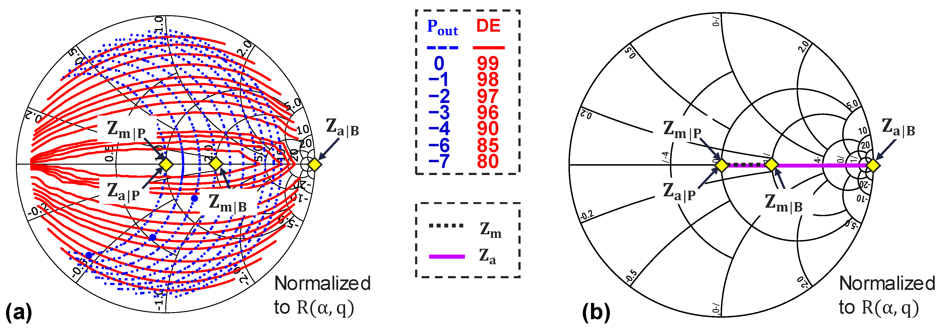
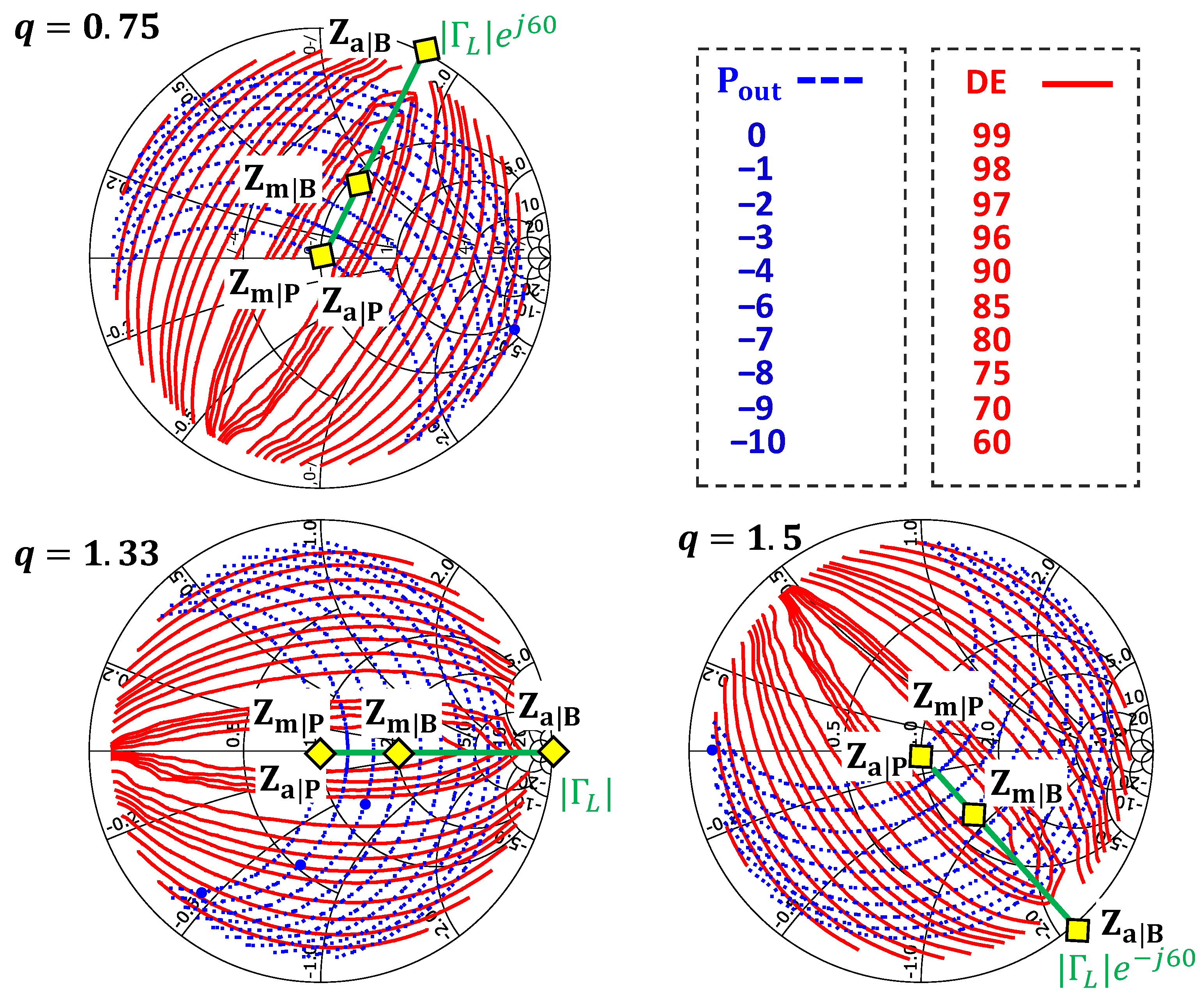
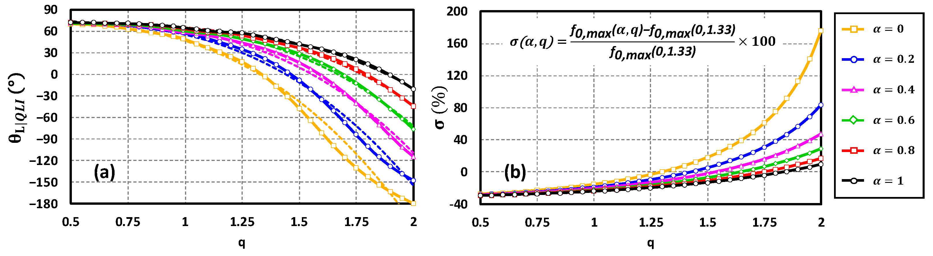
3.2. Extension of QLI Class-E DPA Methodology

The QLI class-E Doherty PA design methodology presented in the previous section applies only for Doherty combiners having pure-real load impedance trajectories. These combiners usually involve one or more quarter-wave transmission lines [2,5], which makes them unsuitable for compact integrated power amplifiers. In order to achieve a compact design, a compact L-C Doherty combiner has been proposed in [8,11] Figure 5a. This L-C combiner is particularly interesting when using class-E Main and Auxiliary Pas, since the combiner components can be merged with the class-E output network elements [8]. However, the impedances Z m and Z a seen by the Main and Auxiliary PAs are no longer pure-real and follow complex impedance trajectories as shown in Figure 5b. Hence, the original QLI methodology cannot be directly applied efficiently.
To extend the QLI class-E design methodology for Doherty combiners with complex impedance trajectories, we propose to investigate the output power and efficiency load-pull contour’s behavior of class-E PA for different q   and α   values. For the sake of simplicity, we will first illustrate the extended QLI methodology for α = 0 , then we generalize it to account for any q   and α   values. As shown in Figure 6, increasing the resonance factor q rotates the load-pull contours in the clockwise direction and vice versa. Note that the alignment between the efficiency and P o u t contours remain the same regardless of q . Hence, the QLI class-E operation can be achieved for complex impedance trajectories. For instance, selecting q = 0.75 allows us to align the QLI high-efficiency region with the impedance trajectories of the L-C Doherty combiner presented on Figure 5b. Moreover, it is now possible to select any q value and use the generalized combiner synthesis technique proposed in [3] to synthesize the required combiner.
To simplify their interpretation, the load-pull contours in Figure 6 can be represented differently by plotting the efficiency and output power versus q sampled at different | Γ L | and θ L , as shown in Figure 7. The data on Figure 7 show that the range of q values for which the class-E QLI DPA operation can be achieved (named the QLI zone) changes depending on θ L . These QLI zones are considered suitable for load-modulated Doherty Pas since the output power varies with | Γ L | while the efficiency remains high. By analyzing Figure 7, we notice that for θ L 0 , there are two potential QLI zones. QLI zone 1 has an increasing output power as | Γ L | decreases, while QLI zone 2 has a decreasing output power, as seen in Figure 7d. However, to achieve the appropriate Doherty operation, the load impedance trajectory | Γ L | presented by the combiner must follow an incremental output power evolution. Hence, when selecting QLI zone 2, Γ L = 0 represents the back-off impedance and the device delivers its maximum power for Γ L > 0 .
To investigate the QLI operation in the presence of the input series inductance L b (i.e., α 0 ), we perform load-pull simulations for α = [ 0 ,   1 ] and q = 0.5 ,   2 ,   and we extract the θ L at which QLI operation occurs (named θ L | Q L I ). Herein, for illustration, we only present the case of QLI zone 1. As can be seen in Figure 8a, for q < 1 , θ L | Q L I shows little variation versus q and α , while for q > 1 , θ L | Q L I can be controlled using q and α . To simplify the usage of the proposed methodology, the data in Figure 8a are fitted to polynomial Equation (9), allowing us to predict the angle θ L | Q L I with a determination coefficient of 0.994.
θ L | Q L I α , q = 34.37 q 3 17.51 q 2 + 38.25 q + 20.28 α 3 + 11.8 α 2                                                                         + 3.36 α + 93.1 q 2 α 69.9 q α 2 39.6 q α + 60.25
The extension of the QLI methodology for any α and q offers PA designers additional flexibility. However, the optimal choice of α and q for a given operation frequency or a given device parasitic (output capacitance,…) should be explored. For example, selecting a given q and α value to align the power and efficiency contours in a given direction will affect the maximum design frequency ( f 0 , m a x ) of the class-E PA. As mentioned in [7], f 0 , m a x is defined as the design frequency at which the capacitance C 1 becomes lower than the device output capacitance ( C d e v ). Hence, by substituting C 1 by   C d e v , f 0 , m a x   can be expressed as follows:
f 0 , m a x α , q = K c α , q   P o u t 2 π   K p α , q   V d d 2 C d e v = P d 2 π   V d d 2 C u K c α , q   K p α , q
where P d   and   C u are the power density (in W/mm) and normalized output capacitance (in F/mm) for a given technology, which are almost constant for a given process and under a given V d d . According to (10), for a given process and under a given V d d , increasing the design parameter q allows us to address a higher operating frequency, regardless of the target   P o u t , as can be seen on Figure 8b, which shows the normalized deviation σ ( α , q ) of f 0 , m a x α , q with respect to   f 0 , m a x ( α = 0 , q = 1.33 ) . Also, reducing the series inductance L b (i.e., reducing α ) for a given q tends to increase the maximum operating frequency. Hence, at this stage, the choice of q and α is a tradeoff between the selected θ L | Q L I and the targeted maximum operating frequency f 0 , m a x .
To address this limitation and to relax the constraints related to the choice of α and q , a transmission line (TL) with a characteristic impedance R ( α , q ) and an electrical length θ x is added between Z L = R ( α , q ) and the class-E network, as shown in Figure 9. Since the load-pull contours are normalized to R ( α , q ) , the transmission line will rotate the load-pull contours by θ x according to:
Γ L , c e = Γ L   e j θ L | Q L I + 2 θ x
Thus, with this additional degree of freedom, the power and efficiency contours can be oriented in any direction, regardless of the choice of q and α . Hence, the designer can match the class-E PA contour orientation to the load-modulated impedance trajectories required by any Doherty combiner while selecting the class-E network parameters q and α based on other design criteria such as operating frequency, bandwidth, network components quality factor and size. For illustration, Figure 10a shows that the QLI behavior can be achieved on the real axis (as required for a conventional Doherty combiner) by selecting q = 0.75 and θ x = 150 ° , where in the original QLI methodology q = 1.33 was the only possible solution. In addition, Figure 10b shows that the QLI load-pull contours profile required by the L-C combiner can be achieved using q = 1.33 and θ x = 40 ° . In fact, with the addition of the transmission line at the output of the class-E network, we can achieve any target QLI angle with any combination of α   and q .

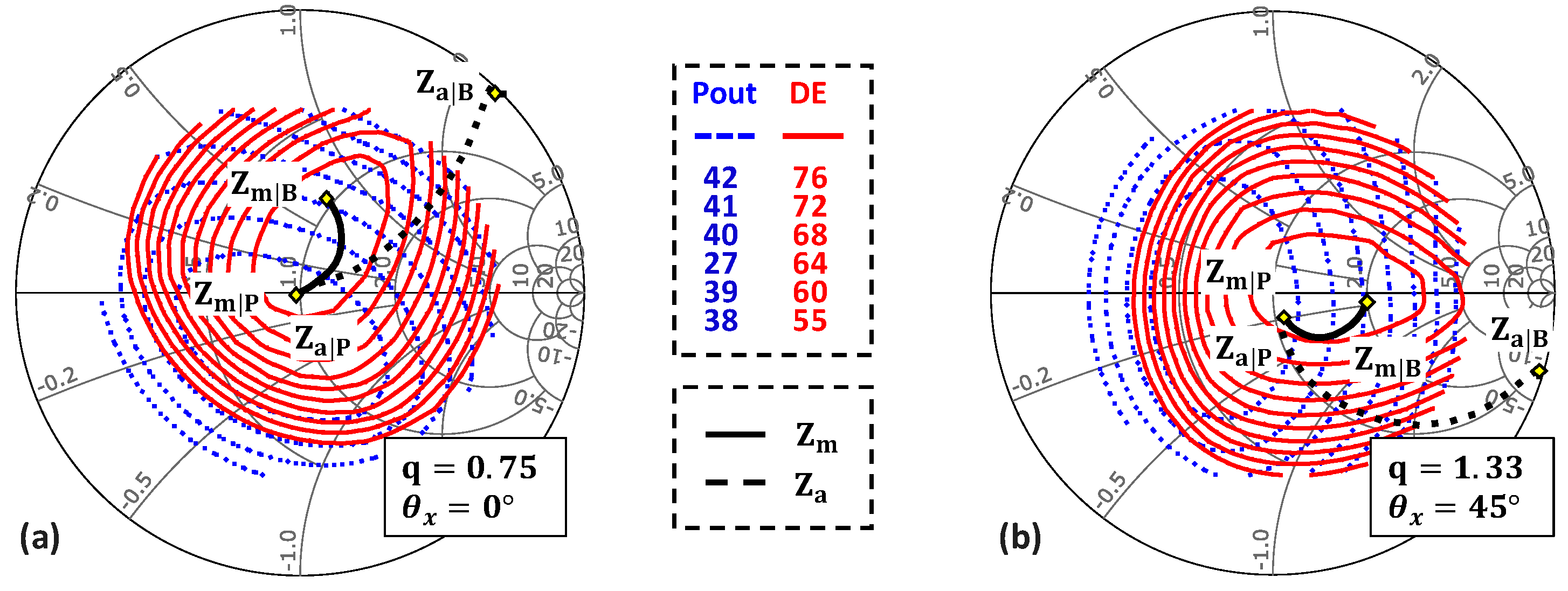
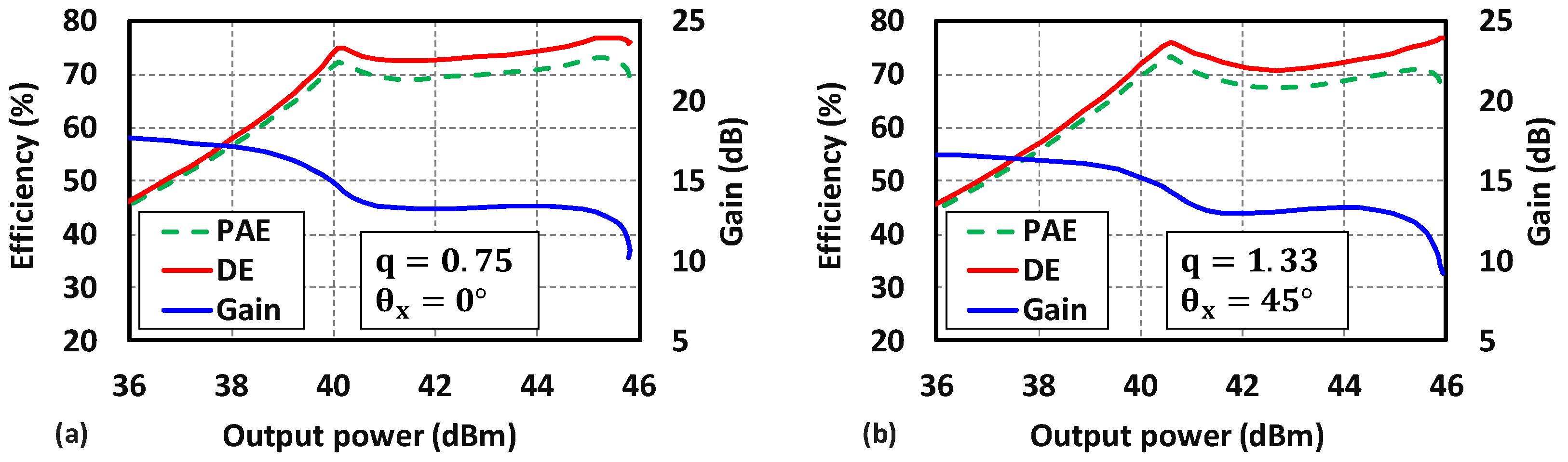
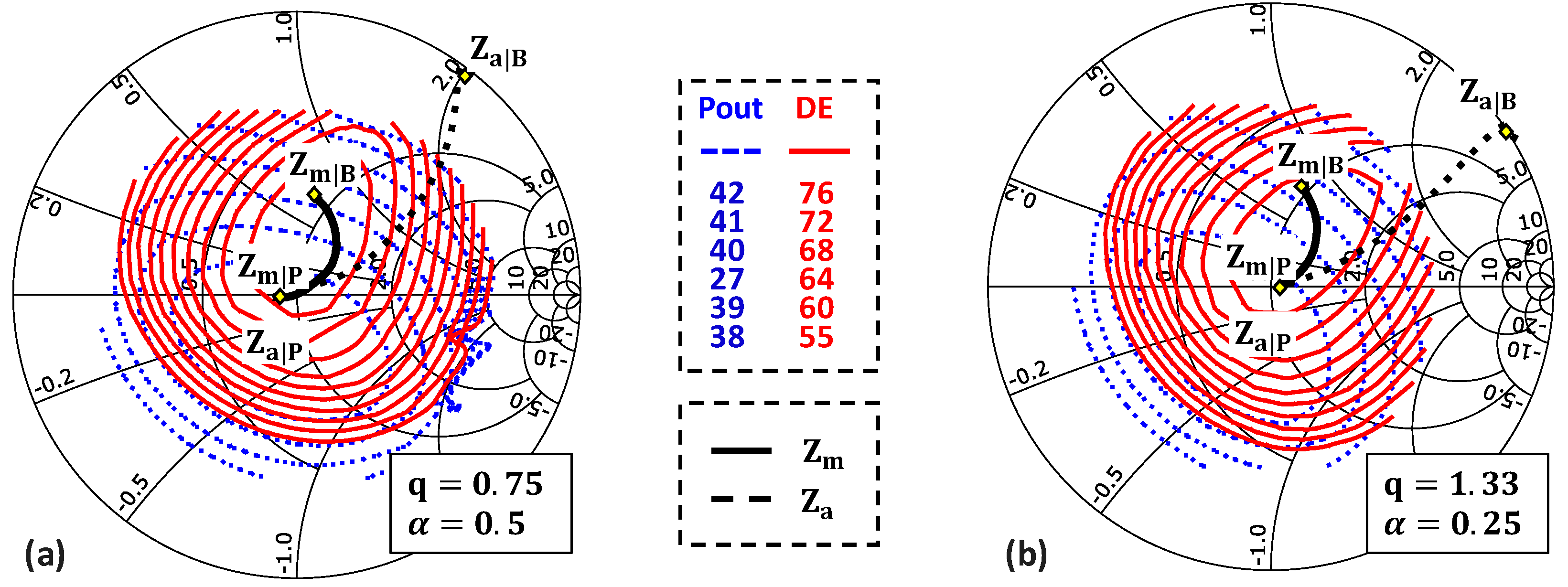
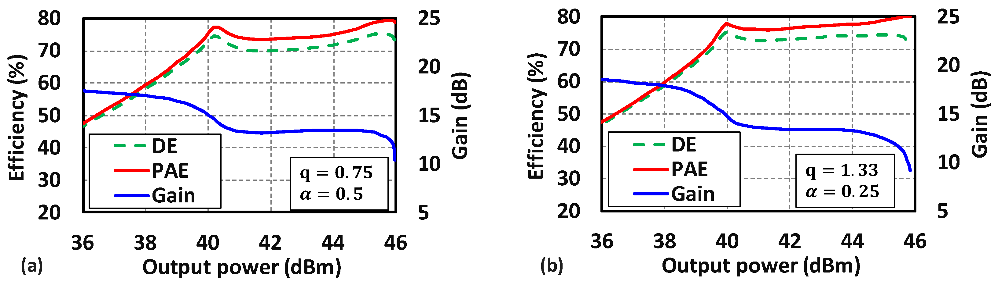
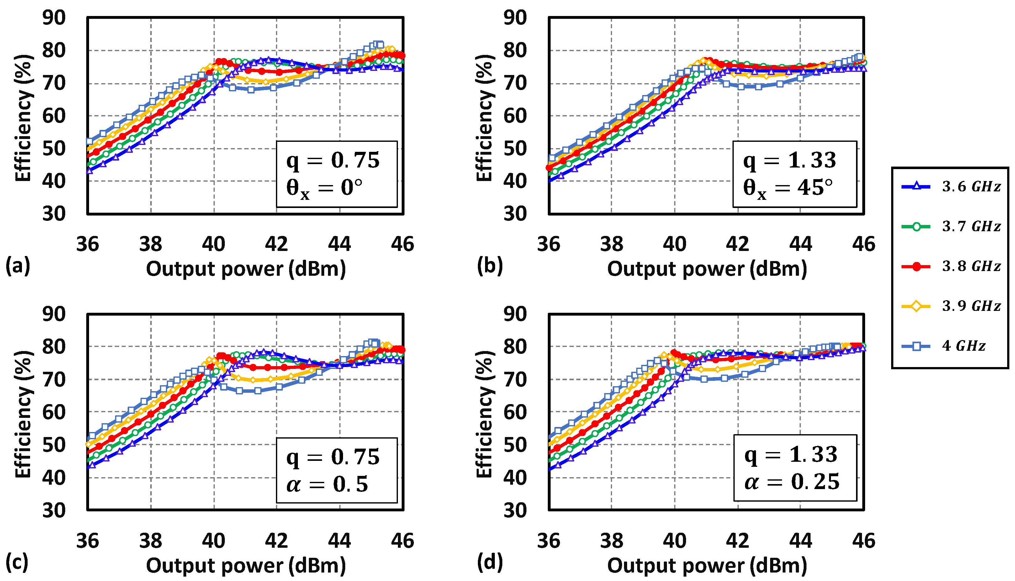
4. Application of the Proposed Design Methodology

To demonstrate the proposed design methodology, two QLI class-E Doherty PA use cases involving a compact L-C combiner are proposed using the CG2H80015D commercial GaN HEMT transistor with two configurations for both designs. In the first use case, similar to our previous paper [12], the class-E network ( α = 0 ) with output TL is used. In the second design, we utilized the generalized class-E network, taking advantage of the contour rotation with α presented in Section 3.2.
The designs target 6 dB OBO and 40 W (46 dBm) of peak output power under 28 V supply voltage at 3.8 GHz. Since the OBO targeted is 6 dB, each PA delivers 20 W at peak output power. One configuration is done for q = 0.75 where θ L | Q L I is directly aligned with the load impedance trajectory of the L-C combiner (i.e., θ L = 60 ° ). The second configuration is done for q = 1.33 and θ L | Q L I needs to be adjusted. The Main device is biased at −2.9 V and the Auxiliary at −5.5 V. Note that in practical design, the input signal drive is sinusoidal, and the device has a non-zero knee voltage and non-linear output capacitance. Moreover, for the targeted design, the parallel capacitance of the network, C 1 , remains lower than the device’s output capacitance, leading to suboptimum class-E operation. Consequently, a tuning factor K R   is introduced to account for these non-idealities. Thus,   R ( α , q ) is now expressed as in (12), while other equations remain unchanged.
R α , q = K R   K P α , q   V d d 2 P o u t
The first use case uses the network of our previous paper, Figure 11, with α = 0 (i.e., L b = 0 ) . The output power and efficiency contours are plotted on plane A considering   K R = 0.375 for q = 0.75 and   K R = 0.395 for q = 1.33 and follow the same trend as the theoretical ones. Note that the input phase has been slightly adjusted to achieve proper load modulation ( Φ a = 105 ° for q = 0.75 and Φ a = 100 ° for q = 1.33 ). For q = 1.33 , θ x is tuned to 45 ° to align the load impedance trajectories with the contours, while for q = 0.75 , the contours are aligned with the load impedance trajectory leading to θ x = 0 . The proposed QLI class-E DPA design is validated using large signal harmonic balance simulation using the CG2H80015D model provided by MACOM and considering a lossy output network with a quality factor of 60 for inductors and 90 for capacitors. The component values are given in Table 1. As shown in Figure 12, the designs realize the expected load modulation trajectories of Z m and Z a and follow the desired P o u t levels inside the high-DE contours.
As shown in Figure 13, both DPAs achieve a saturated output power of around 46 dBm, with more than 70% drain efficiency (DE) over the 6 dB OBO and a large signal power gain of around 13 dB.
The second use case, Figure 14, illustrates the case where the QLI angle θ Q L I is controlled by the choice of α and q for α 0 . This is particularly interesting when the device used for the design is packaged and includes a wire-bonding, or if the power cells are wire-bonded to the output network in a quasi-MMIC-like assembly. Note that the output series branch of the class-E network ( L 0 , C 0 and j X ) is merged with the L-C combiner elements which results in a more compact overall output network. Also, as mentioned previously, the capacitance C 1 is absorbed into the output capacitance of the device.
The output power and efficiency contours are plotted on plane A in Figure 15, considering   K R = 0.375 for q = 0.75 and   K R = 0.395 for q = 1.33 . Note that the input phase has been slightly adjusted to achieve proper load modulation ( Φ a = 105 ° for q = 0.75 and Φ a = 105 ° for q = 1.33 ). For q = 0.75 , the bond wire can be added without affecting θ L since α has almost no effect on θ L as presented in Figure 8a. Thus, α is selected to be 0.25 to present an achievable bond-wire inductance of L b = 0.7 n H . For q = 1.33 , α affects the QLI operation angle. Hence, using (5), α is selected to be 0.5 ( L b = 0.6   n H ) in order to align the contours with the load modulation of the L-C combiner. The component values are given in Table 2. As shown in Figure 15, both designs achieve proper load modulation since the trajectories of Z m and Z a cross the desired P o u t levels inside the DE contours region.
As shown in Figure 16, both DPAs achieve a saturated output power of around 46 dBm, with more than 70% drain efficiency (DE) over the 6 dB OBO and a large signal power gain of around 13 dB.
The four configurations have been simulated from 3.6 GHz to 4 GHz to observe the potential wideband operation of the proposed designs. To increase the bandwidth of each configuration, the loaded quality factor Q L is reduced to one. The drain efficiency versus output power is plotted on Figure 17 from 3.6 GHz to 4 GHz. As one can see in Figure 17, each configuration operates properly in the band. The configuration q = 1.33 and θ x = 45 ° (Figure 17b) seems to be the best configuration to address the 3.6 GHz to 4 GHz band, while for q = 0.75 and α = 0.5 (Figure 17c), the efficiency and output power are degraded in the upper band. This shows that the choice of θ x , q and α has to be carefully decided to achieve a wider band.
Table 3 provides a comparative summary of the existing Doherty QLI class-Es and the best configuration of our work for wideband operation. This work achieves the best efficiency of 70% over 6 dB OBO and an output power of 46 dBm from 3.6 GHz to 4 GHz. Ref. [6] achieved a wider bandwidth, while the efficiency at OBO dropping. Ref. [7] achieved the same bandwidth with a larger OBO and reduced efficiency compared to this work.
The simulation results validated the proposed QLI class-E DPA design methodology, showing that the uses of an output transmission line and a wisely chosen α can allow us to decorrelate the choice of q and the combiner choice in a practical case. This offers PA designers more flexibility when selecting the suitable class-E output network solution and the corresponding Doherty combiner according to the application requirement and the design constraints, such as the device parasitics and output network size.

5. Conclusions

In conclusion, this study extends the QLI class-E Doherty PA design space for complex load impedance trajectories and generalized class-E networks. It simulates the design of high-efficiency Doherty PA using combiners that present a complex-to-real impedance trajectory. Adjusting the class-E network resonance factor q and the series inductance L b enables QLI operation with various types of Doherty combiner. A suitable equation for the QLI angle is provided, allowing us to predict the angle of QLI operation for any q and α in the given range. A novel approach using a transmission line at the output of class-E network mitigates the maximum operating frequency limitation caused by the resonance factor and series inductance choice and reduces the constraint on the choice of q and   α . Finally, the methodology is validated with two different 40 W Doherty PA designs. One uses the proposed output transmission line approach considering no series inductance (i.e., α = 0 ) ,   and the second one takes advantage of the series inductance L b . All of the designed class-E QLI Doherty PAs achieve over 70% efficiency across a 6 dB-output power back-off at 3.8 GHz when simulated.

Author Contributions

Conceptualization: M.O. and A.S.; writing: M.O. and A.S.; Reviewing: A.S., J.-D.A., E.L.-L., P.R. and A.G.; Supervision: A.S., J.-D.A., E.L.-L. and A.G. All authors have read and agreed to the published version of the manuscript.

Funding

This work was supported by the ANR under the France 2030 program, grant NF-PERSEUS: ANR-22-PEFT-0004.

Institutional Review Board Statement

Not applicable.

Informed Consent Statement

Not applicable.

Data Availability Statement

The data presented in this study are available on request from the corresponding author due to privacy.

Conflicts of Interest

The authors declare no conflicts of interest.

Appendix A

The analytical solution of the generalized class-E network, Figure 1, was presented typo errors. These equations marked in bold are from [9], expressed in (A1) and (A2).
C 2 = π Q cos π Q sin π Q Q p Q 2 1 cos ϕ Q sin π Q Q 2 2 Q 2 sin ϕ cos π Q
and
tan ϕ = π + π cos π ϕ + 2 Q s i n π Q 2 Q 2 1 1 cos π Q + Q π sin π Q  
The corrected equations are given in (A3) and (A4):
C 2 = π Q cos π Q sin π Q Q p Q 2 1 cos ϕ Q sin π Q + Q 2 2 Q 2 sin ϕ cos π Q
and
tan ϕ = π + π cos π Q + 2 Q s i n π Q 2 Q 2 1 1 cos π Q + Q π sin π Q  

References

  1. Giry, A.; Serhan, A.; Parat, D.; Reynier, P. Linear Power Amplifiers for Sub-6GHz Mobile Applications: Progress and Trends. In Proceedings of the 2020 18th IEEE International New Circuits and Systems Conference (NEWCAS), Montreal, QC, Canada, 16–19 June 2020; pp. 226–229. [Google Scholar]
  2. Doherty, W.H. A New High Efficiency Power Amplifier for Modulated Waves. Proc. IRE 1936, 24, 1163–1182. [Google Scholar] [CrossRef]
  3. Ozen, M.; van der Heijden, M.; Acar, M.; Jos, R.; Fager, C. A Generalized Combiner Synthesis Technique for Class-E Outphasing Transmitters. IEEE Trans. Circuits Syst. Regul. Pap. 2017, 64, 1126–1139. [Google Scholar] [CrossRef]
  4. Srirattana, N.; Raghavan, A.; Heo, D.; Allen, P.E.; Laskar, J. Analysis and design of a high-efficiency multistage Doherty power amplifier for wireless communications. IEEE Trans. Microw. Theory Tech. 2005, 53, 852–860. [Google Scholar] [CrossRef]
  5. Qureshi, J.H.; Sneijers, W.; Keenan, R.; deVreede, L.C.N.; van Rijs, F. A 700-W peak ultra-wideband broadcast Doherty amplifier. In Proceedings of the 2014 IEEE MTT-S International Microwave Symposium (IMS2014), Tampa, FL, USA, 1–6 June 2014; pp. 1–4. [Google Scholar]
  6. Qureshi, A.R.; Acar, M.; Pires, S.C.; de Vreede, L.C.N. High Efficiency and Wide Bandwidth Quasi-Load Insensitive Class-E Operation Utilizing Package Integration. IEEE Trans. Microw. Theory Tech. 2018, 66, 5310–5321. [Google Scholar] [CrossRef]
  7. Nghiem, X.A.; Gajadharsing, J. Continuous Quasi-Load Insensitive Class-E Mode for Wideband Doherty Power Amplifiers. In Proceedings of the 2023 IEEE/MTT-S International Microwave Symposium—IMS 2023, San Diego, CA, USA, 11–16 June 2023; pp. 450–453. [Google Scholar]
  8. Bachi, J.; Serhan, A.; Pham, D.-K.G.; Parat, D.; Reynier, P.; Desgreys, P.; Giry, A. A Novel Approach for Doherty PA Design Using a Compact L-C Combiner. IEEE Trans. Circuits Syst. II Express Briefs 2022, 69, 4023–4027. [Google Scholar] [CrossRef]
  9. Rong, C.; Liu, X.; Xu, Y.; Xia, M. Analysis and Design of Class E Power Amplifier with Finite DC-Feed Inductance and Series Inductance Network. ACES J. Pap. 2017, 32, 455–462. [Google Scholar]
  10. Acar, M.; Annema, A.J.; Nauta, B. Analytical Design Equations for Class-E Power Amplifiers. IEEE Trans. Circuits Syst. Regul. Pap. 2007, 54, 2706–2717. [Google Scholar] [CrossRef]
  11. Takenaka, K.; Sato, T.; Matsumoto, H.; Kawashima, M.; Nakajima, N. New compact Doherty power amplifier design for handset applications. In Proceedings of the 2017 IEEE Topical Conference on RF/Microwave Power Amplifiers for Radio and Wireless Applications (PAWR), Phoenix, AZ, USA, 15–18 January 2017; pp. 81–83. [Google Scholar]
  12. Otmani, M.; Serhan, A.; Arnould, J.-D.; Lauga-Larroze, E.; Giry, A. Extension of Quasi-Load Insensitive Class-E Doherty Operation with Complex Load Trajectories. In Proceedings of the 2024 19th Conference on Ph.D Research in Microelectronics and Electronics (PRIME), Larnaca, Cyprus, 9–12 June 2024; pp. 1–4. [Google Scholar]
Figure 1. Schematic of Class-E PA with generalized output matching network [9].
Chips 04 00026 g001
Figure 2. K L , K C , K x and K P for q = [ 0.5 : 2 ] and α = [ 0 : 1 ] .
Chips 04 00026 g002
Figure 3. (a) Original QLI 6-dB DPA, (b) Efficiency versus OBO for QLI DPA ( q = 1.33, α = 0 ).
Chips 04 00026 g003
Figure 4. (a) Normalized output power and efficiency load-pull contours for class-E PA with q = 1.33 and α = 0. (b) Load impedance trajectories of the Conventional 6 dB Doherty combiner.
Chips 04 00026 g004
Figure 5. (a) L-C Doherty combiner [8] and (b) load trajectories of L-C Doherty combiner.
Chips 04 00026 g005
Figure 6. Normalized output power and efficiency load-pull contours for Class-E PA for various resonance factor q .
Chips 04 00026 g006
Figure 7. (ac): Efficiency and (df): normalized output power versus q sampled at different | Γ L | and for θ L = 60°, 0° and −60°. α = 0 .
Chips 04 00026 g007
Figure 8. (a) Solid line: θ L | Q L I versus q for α = [ 0 : 1 ] step 0.2, dashed line: fitted   θ L | Q L I and (b) normalized deviation of f 0 , m a x ( α , q ) with respect to f 0 , m a x   ( α = 0 , q = 1.33 ) for α = [ 0 : 1 ] step 0.2.
Chips 04 00026 g008
Figure 9. Schematic of Class-E PA with generalized load network and additional output transmission line.
Chips 04 00026 g009
Figure 10. Output power and efficiency contours of ideal class-E PA with α = 0 and (a) q = 0.75 and θ x = 150 ° and (b) q = 1.33 and θ x = 40 °.
Chips 04 00026 g010
Figure 11. Proposed class-E Doherty PA using L-C combiner without L b (i.e., α = 0 ) .
Chips 04 00026 g011
Figure 12. Power and efficiency load-pull contours,   Z m and Z a on plane A for: (a) q = 0.75 and   θ x = 0 ° and (b) q = 1.33 and θ x = 45 ° .
Chips 04 00026 g012
Figure 13. Simulated performance of the QLI class-E Doherty PAs with L-C combiner for: (a) q = 0.75 and θ x = 0 ° and (b) q = 1.33 and θ x = 45 ° .
Chips 04 00026 g013
Figure 14. Schematic of the proposed class-E QLI Doherty PA with L-C combiner for α 0 .
Chips 04 00026 g014
Figure 15. Power and efficiency load-pull contours,   Z m and Z a on plane A for: (a) q = 0.75 and   α = 0.5 and (b) q = 1.33 and α = 0.25 .
Chips 04 00026 g015
Figure 16. Simulated performance of the QLI class-E Doherty PAs with L-C combiner for: (a) q = 0.75 and α = 0.5 , (b) q = 1.33 and α = 0.25 .
Chips 04 00026 g016
Figure 17. Simulated DE versus output power of the QLI class-E Doherty PAs with L-C combiner for: (a) q = 0.75 and θ x = 0 ° , (b) q = 1.33 and θ x = 45 ° , (c) q = 0.75 and α = 0.5 , and (d) q = 1.33 and α = 0.25 .
Chips 04 00026 g017
Table 1. Output network parameters for first use case α = 0 .
Parameters C 1 L 1 L s , m C s , m L s , a C s , a θ x L c C c R
UnitpFnHnHpFnHpF°nHpF Ω
q = 0.75 0.8 2.71.72.91.11.400014.2
q = 1.33 111.31.61.31.6401.11.626
Table 2. Output network parameters for second use case ( α 0 ) .
Parameters C 1 L b L 1 L s , m C s , m L s , a C s , a R
UnitpFnHnHnHpFnHpF Ω
q = 0.75 0.80.72.80.82.90.41.79.5
q = 1.33 0.80.61.20.82.90.41.89
Table 3. Comparison with other Doherty QLI Class-Es.
Ref.Frequency
(GHz)
OBO
(dB)
Efficiency @ Peak (%)Efficiency @ OBO (%)Psat
(dBm)
Combiner Type
[6]1.4–2.6673–6856–4148.2–45.2Inverter
[7]3.4–3.87.550–6052.7–53.648–48.25Inverter
This work *
q = 1.33, θ x = 45 °
3.6–4674.5–7870.3–76.745.8–46.1 L-C
* Simulation results.
Disclaimer/Publisher’s Note: The statements, opinions and data contained in all publications are solely those of the individual author(s) and contributor(s) and not of MDPI and/or the editor(s). MDPI and/or the editor(s) disclaim responsibility for any injury to people or property resulting from any ideas, methods, instructions or products referred to in the content.

