Thermal Analysis and Evaluation of Memristor-Based Compute-in-Memory Chips


Abstract
:1. Introduction
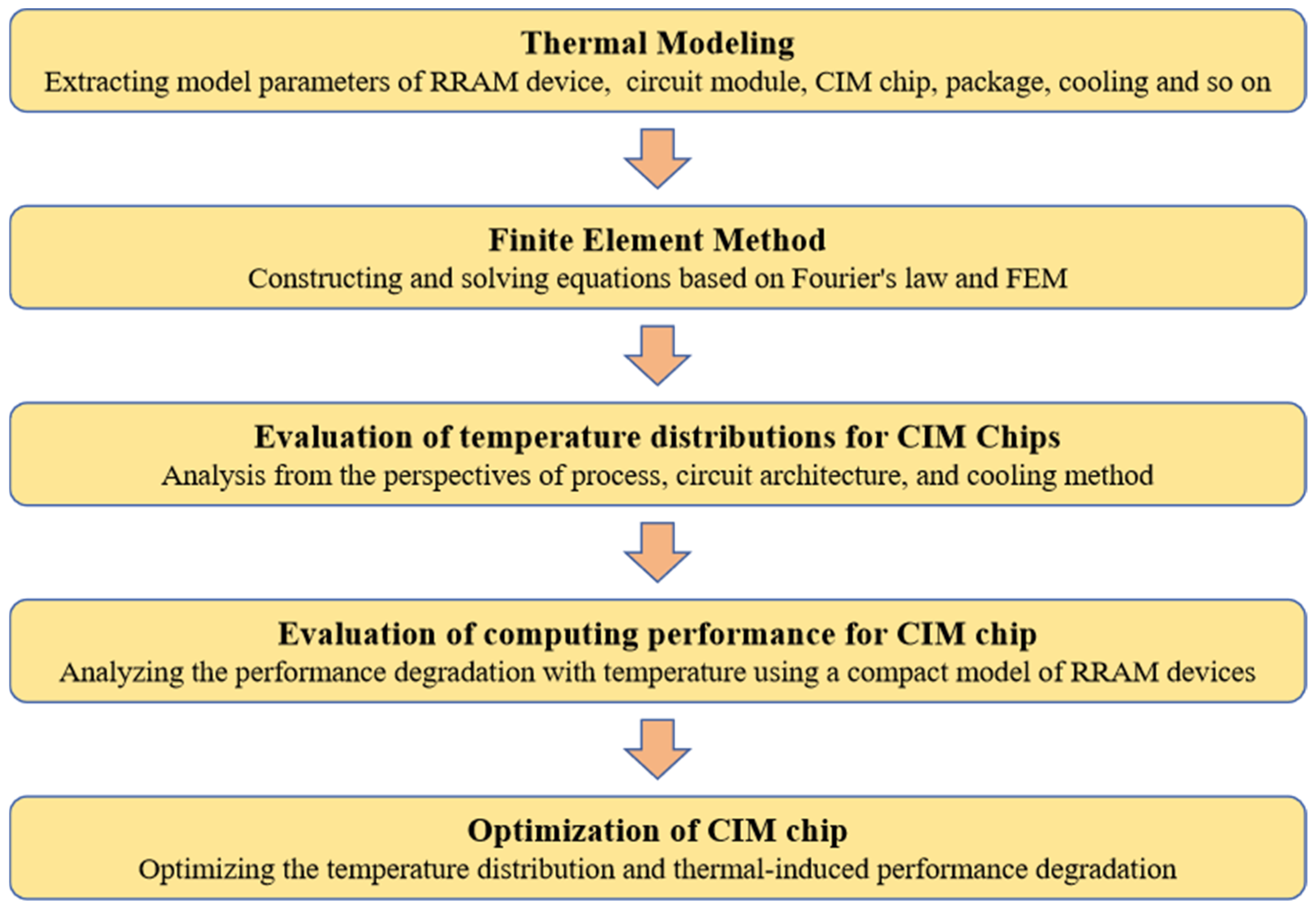
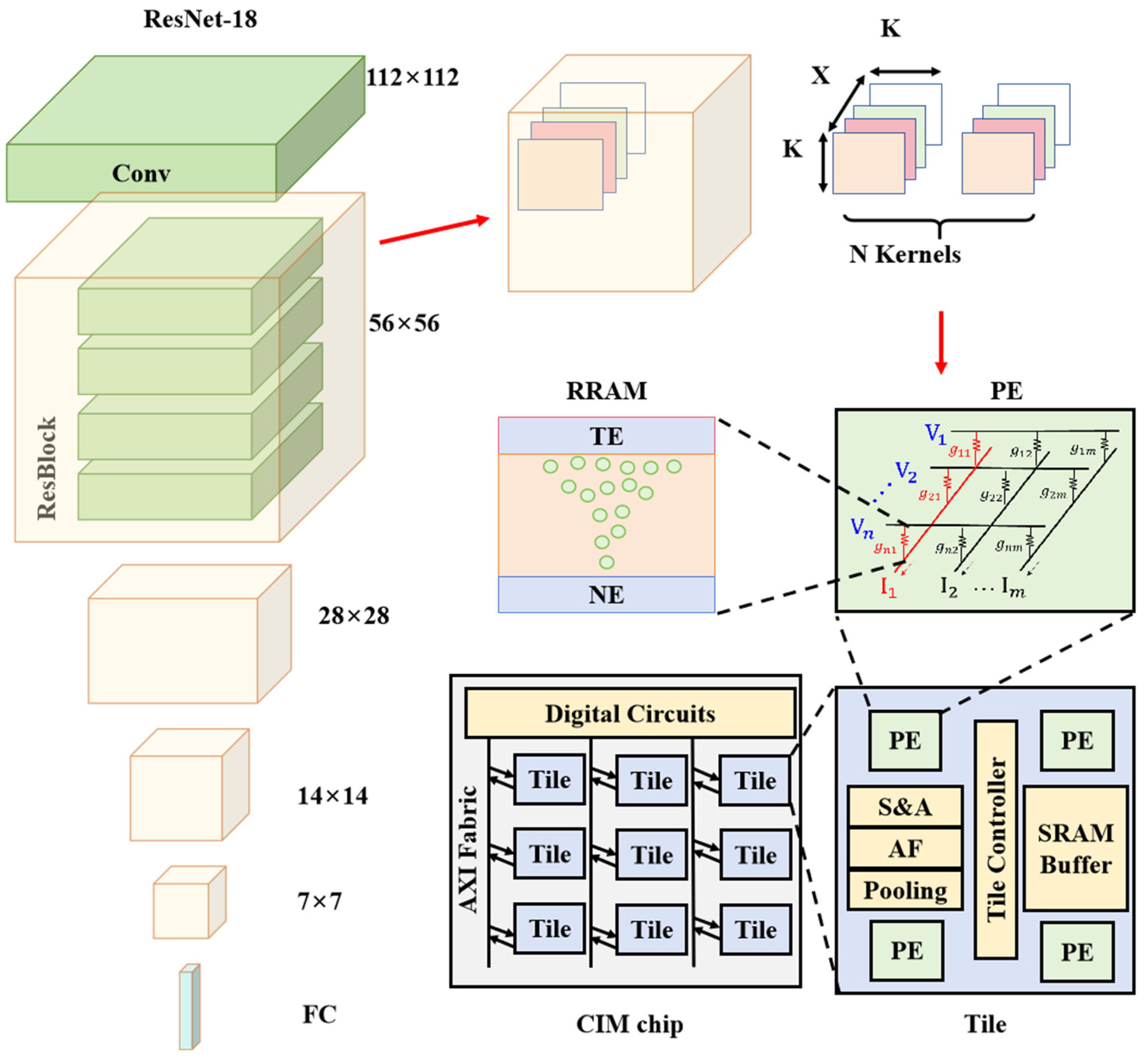
2. Thermal Modeling
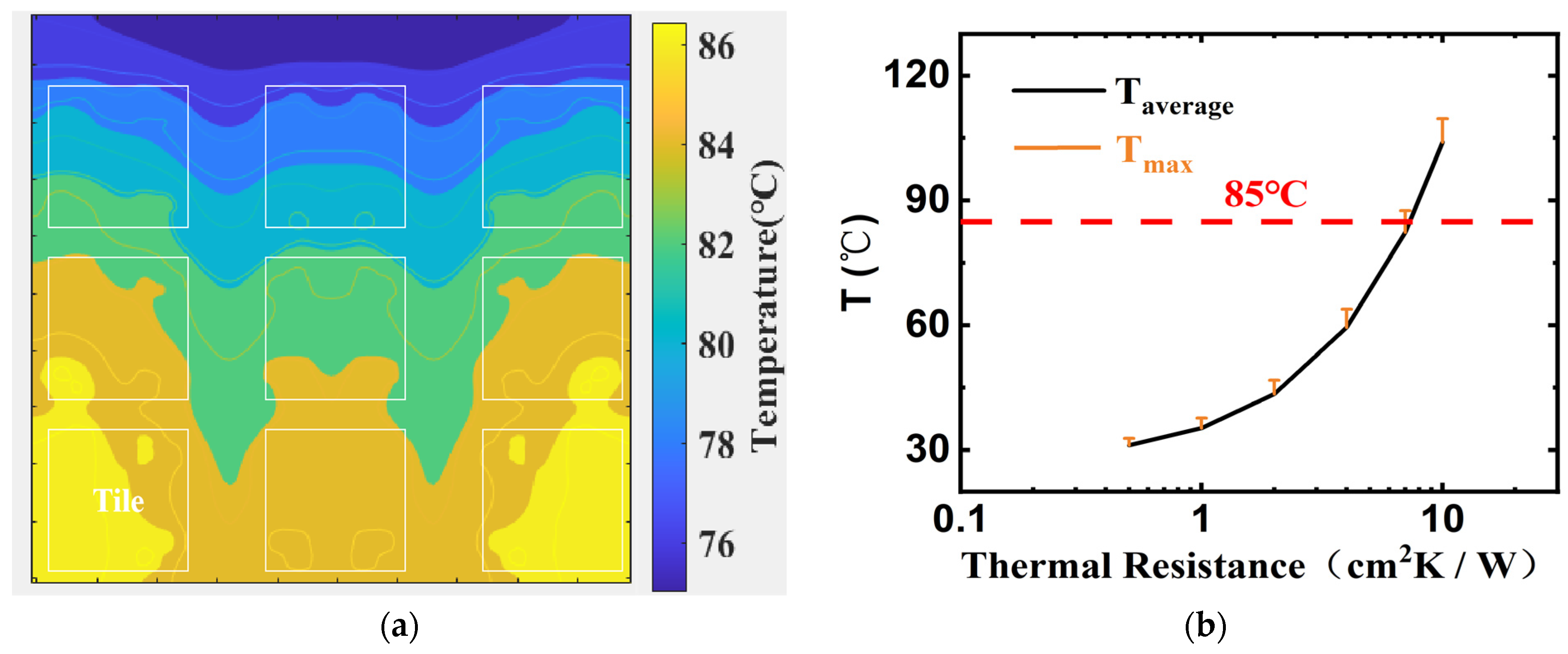
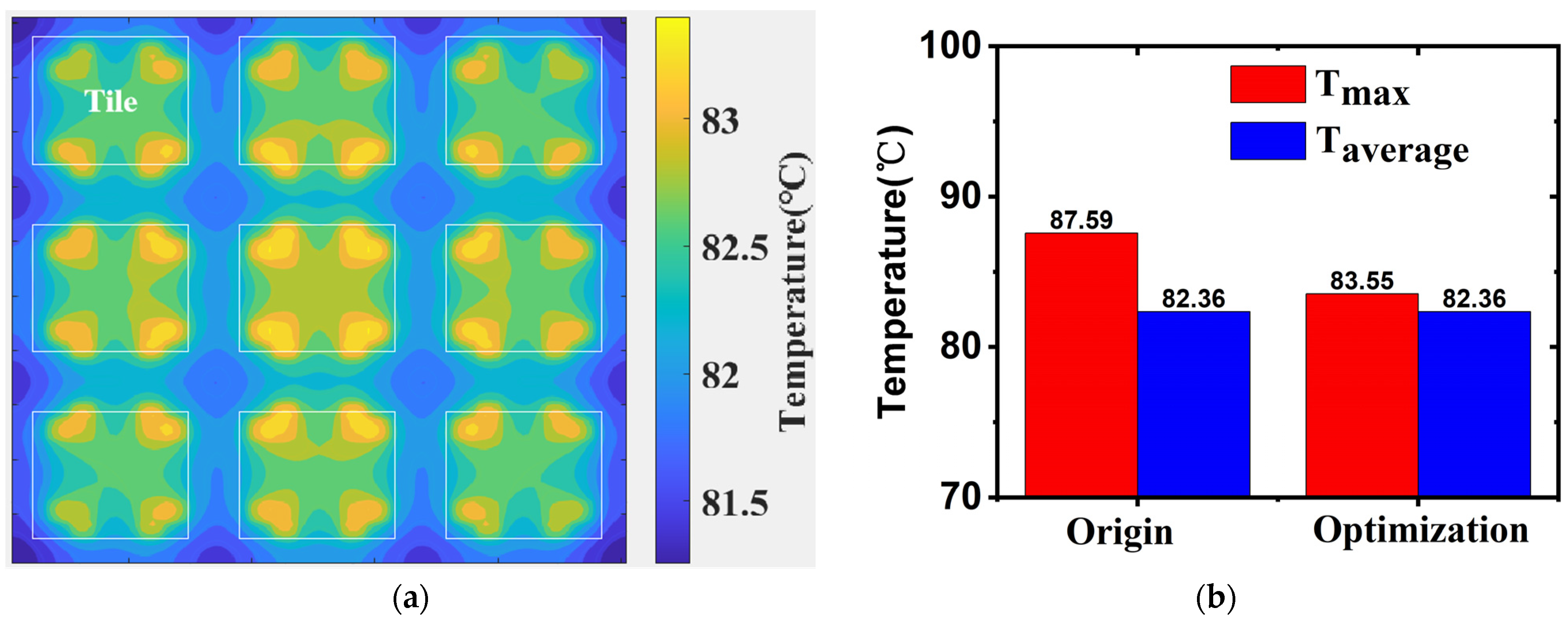
3. Results of Thermal Effect Evaluation
4. Conclusions
Author Contributions
Funding
Institutional Review Board Statement
Informed Consent Statement
Data Availability Statement
Conflicts of Interest
References
- Feng, S.; Yan, X.; Sun, H.; Feng, Y.; Liu, H.X. Intelligent driving intelligence test for autonomous vehicles with naturalistic and adversarial environment. Nat. Commun. 2021, 12, 748. [Google Scholar] [CrossRef] [PubMed]
- Chang, Y.; Wang, X.; Wang, J.; Wu, Y.; Yang, L.; Zhu, K.; Chen, H.; Yi, X.; Wang, C.; Wang, Y.; et al. A survey on evaluation of large language models. ACM Trans. Intell. Syst. Technol. 2024, 15, 1–45. [Google Scholar] [CrossRef]
- Sandhu, A.K. Big data with cloud computing: Discussions and challenges. Big Data Min. Anal. 2021, 5, 32–40. [Google Scholar] [CrossRef]
- Strubell, E.; Ganesh, A.; McCallum, A. Energy and policy considerations for modern deep learning re-search. In Proceedings of the AAAI Conference on Artificial Intelligence, New York, NY, USA, 7–12 February 2020; Volume 34. [Google Scholar]
- Haensch, W.; Raghunathan, A.; Roy, K.; Chakrabarti, B.; Phatak, C.M.; Wang, C.; Guha, S. Compute in-memory with non-volatile elements for neural networks: A review from a co-design perspective. Adv. Mater. 2023, 35, 2204944. [Google Scholar] [CrossRef] [PubMed]
- Horowitz, M. 1.1 computing’s energy problem (and what we can do about it). In Proceedings of the 2014 IEEE International Solid-State Circuits Conference Digest of Technical Papers (ISSCC), San Francisco, CA, USA, 9–13 February 2014. [Google Scholar]
- Wong, H.-S.P.; Salahuddin, S. Memory leads the way to better computing. Nat. Nanotechnol. 2015, 10, 191–194. [Google Scholar] [CrossRef] [PubMed]
- Ielmini, D.; Wong, H.-S.P. In-memory computing with resistive switching devices. Nat. Electron. 2018, 1, 333–343. [Google Scholar] [CrossRef]
- Zidan, M.A.; Strachan, J.P.; Lu, W.D. The future of electronics based on memristive systems. Nat. Electron. 2018, 1, 22–29. [Google Scholar] [CrossRef]
- Lanza, M.; Sebastian, A.; Lu, W.D.; Le Gallo, M.; Chang, M.F.; Akinwande, D.; Puglisi, F.M.; Alshareef, H.N.; Liu, M.; Roldan, J.B. Memristive technologies for data storage, computation, encryption, and radio-frequency communication. Science 2022, 376, eabj9979. [Google Scholar] [CrossRef] [PubMed]
- Wan, W.; Kubendran, R.; Schaefer, C.; Eryilmaz, S.B.; Zhang, W.; Wu, D.; Deiss, S.; Raina, P.; Qian, H.; Gao, B.; et al. A compute-in-memory chip based on resistive random-access memory. Nature 2022, 608, 504–512. [Google Scholar] [CrossRef] [PubMed]
- Feng, Y.; Zhang, Y.; Zhou, Z.; Huang, P.; Liu, L.; Liu, X.; Kang, J. Memristor-based storage system with convolutional autoencoder-based image compression network. Nat. Commun. 2024, 15, 1132. [Google Scholar] [CrossRef] [PubMed]
- Yuan, R.; Tiw, P.J.; Cai, L.; Yang, Z.; Liu, C.; Zhang, T.; Ge, C.; Huang, R.; Yang, Y. A neuromorphic physiological signal processing system based on VO2 memristor for next-generation hu-man-machine interface. Nat. Commun. 2023, 14, 3695. [Google Scholar] [CrossRef] [PubMed]
- Shen, Z.; Zhao, C.; Qi, Y.; Xu, W.; Liu, Y.; Mitrovic, I.Z.; Yang, L.; Zhao, C. Advances of RRAM Devices: Resistive Switching Mechanisms, Materials and Bionic Synaptic Application. Nanomaterials 2020, 10, 1437. [Google Scholar] [CrossRef] [PubMed]
- Roldán, J.B.; Miranda, E.; Maldonado, D.; Mikhaylov, A.N.; Agudov, N.V.; Dubkov, A.A.; Koryazhkina, M.N.; González, M.B.; Villena, M.A.; Poblador, S.; et al. Variability in resistive memories. Adv. Intell. Syst. 2023, 5, 2200338. [Google Scholar] [CrossRef]
- Roldán, J.B.; Cantudo, A.; Maldonado, D.; Aguilera-Pedregosa, C.; Moreno, E.; Swoboda, T.; Jiménez-Molinos, F.; Yuan, Y.; Zhu, K.; Lanza, M.; et al. Thermal Compact Modeling and Resistive Switching Analysis in Titanium Oxide-Based Memristors. ACS Appl. Electron. Mater. 2024, 6, 1424–1433. [Google Scholar] [CrossRef] [PubMed]
- Kaul, A.; Luo, Y.; Peng, X.; Yu, S.; Bakir, M.S. Thermal reliability considerations of resistive synaptic devices for 3D CIM system performance. In Proceedings of the 2021 IEEE International 3D Systems Integration Conference (3DIC), Raleigh, NC, USA, 26–29 October 2021. [Google Scholar]
- Chen, W.-H.; Dou, C.; Li, K.-X.; Lin, W.-Y.; Li, P.-Y.; Huang, J.-H.; Wang, J.-H.; Wei, W.-C.; Xue, C.-X.; Chiu, Y.-C.; et al. CMOS-integrated memristive non-volatile computing-in-memory for AI edge processors. Nat. Electron. 2019, 2, 420–428. [Google Scholar] [CrossRef]
- Hung, J.M.; Xue, C.X.; Kao, H.Y.; Huang, Y.H.; Chang, F.C.; Huang, S.P.; Liu, T.W.; Jhang, C.J.; Su, C.I.; Khwa, W.S.; et al. A four-megabit compute-in-memory macro with eight-bit precision based on CMOS and resistive random access memory for AI edge devices. Nat. Electron. 2021, 4, 921–930. [Google Scholar] [CrossRef]
- Xue, C.X.; Chen, W.H.; Liu, J.S.; Li, J.F.; Lin, W.Y.; Lin, W.E.; Wang, J.H.; Wei, W.C.; Chang, T.W.; Chang, T.C.; et al. 24.1 A 1Mb multibit ReRAM computing-in-memory macro with 14.6 ns parallel MAC computing time for CNN based AI edge processors. In Proceedings of the 2019 IEEE International Solid-State Circuits Conference-(ISSCC), San Francisco, CA, USA, 17–21 February 2019. [Google Scholar]
- Xue, C.-X.; Chiu, Y.-C.; Liu, T.-W.; Huang, T.-Y.; Liu, J.-S.; Chang, T.-W.; Kao, H.-Y.; Wang, J.-H.; Wei, S.-Y.; Lee, C.-Y.; et al. A CMOS-integrated compute-in-memory macro based on resistive random-access memory for AI edge devices. Nat. Electron. 2021, 4, 81–90. [Google Scholar] [CrossRef]
- Ma, A.; Gao, B.; Liu, Y.; Yao, P.; Liu, Z.; Du, Y.; Li, X.; Xu, F.; Hao, Z.; Tang, J.; et al. Multi-scale thermal modeling of RRAM-based 3D monolithic-integrated computing-in-memory chips. In Proceedings of the 2022 International Electron Devices Meeting (IEDM), San Francisco, CA, USA, 28–30 November 2022; pp. 15.5.1–15.5.4. [Google Scholar]
- Kaul, A.; Peng, X.; Rajan, S.K.; Yu, S.; Bakir, M.S. Thermal modeling of 3D polylithic integration and implications on BEOL RRAM performance. In Proceedings of the 2020 IEEE International Electron Devices Meeting (IEDM), San Francisco, CA, USA, 12–18 December 2020; pp. 13.1.1–13.1.4. [Google Scholar]
- Xu, M.; Gao, B.; Xu, F.; Wu, W.; Tang, J.; Chen, J.; Qian, H. A Compact Model of Analog RRAM Considering Temperature Coefficient for Neural Network Evaluation. In Proceedings of the 2021 5th IEEE Electron Devices Technology & Manufacturing Conference (EDTM), Chengdu, China, 8–11 April 2021. [Google Scholar]
- Ma, A.; Gao, B.; Mou, X.; Yao, P.; Du, Y.; Tang, J.; Qian, H.; Wu, H. Thermal Induced Retention Degradation of RRAM-based Neuromorphic Computing Chips. In Proceedings of the 2023 IEEE International Reliability Physics Symposium (IRPS), Monterey, CA, USA, 26–30 March 2023; pp. 1–6. [Google Scholar]
- Shim, W.; Meng, J.; Peng, X.; Seo, J.-S.; Yu, S. Impact of multilevel retention characteristics on RRAM based DNN inference engine. In Proceedings of the 2021 IEEE International Reliability Physics Symposium (IRPS), Monterey, CA, USA, 21–25 March 2021; pp. 1–4. [Google Scholar]
- He, K.; Zhang, X.; Ren, S.; Sun, J. Deep residual learning for image recognition. In Proceedings of the IEEE Conference on Computer Vision and Pattern Recognition, Las Vegas, NV, USA, 27–30 June 2016. [Google Scholar]
- Krizhevsky, A.; Hinton, G. Learning Multiple Layers of Features from Tiny Images. Available online: http://www.cs.utoronto.ca/~kriz/learning-features-2009-TR.pdf (accessed on 1 February 2025).
- Son, K.; Park, J.; Kim, S.; Sim, B.; Kim, K.; Choi, S.; Kim, H.; Kim, J. Thermal Analysis of High Bandwidth Memory (HBM)-GPU Module considering Power Consumption. In Proceedings of the 2023 IEEE Electrical Design of Advanced Packaging and Systems (EDAPS), Rose-Hill, Mauritius, 12–14 December 2023. [Google Scholar]


| Parameters | Value |
|---|---|
| RRAM array | 1152 × 1024 |
| Condutance | 2~20 μS |
| Set voltage | 2.5 V |
| Reset voltage | 2 V |
| Read voltage | ≤0.5 V |
| Technology | 28 nm |
| ADCs per PE | 128 |
| DACs per PE | 1152 |
| Digital power per Tile | 200 mW |
| Digital power except Tiles | 200 mW |
| ADCs power per PE | 80 mW |
| DACs power per PE | 60 mW |
| Thermal conductivity of Si | 149 W/m/K |
| Thermal conductivity of EMC | 1.4 W/m/K |
Disclaimer/Publisher’s Note: The statements, opinions and data contained in all publications are solely those of the individual author(s) and contributor(s) and not of MDPI and/or the editor(s). MDPI and/or the editor(s) disclaim responsibility for any injury to people or property resulting from any ideas, methods, instructions or products referred to in the content. |
© 2025 by the authors. Licensee MDPI, Basel, Switzerland. This article is an open access article distributed under the terms and conditions of the Creative Commons Attribution (CC BY) license (https://creativecommons.org/licenses/by/4.0/).
Share and Cite
Ma, A.; Gao, B.; Yao, P.; Tang, J.; Qian, H.; Wu, H. Thermal Analysis and Evaluation of Memristor-Based Compute-in-Memory Chips. Chips 2025, 4, 9. https://doi.org/10.3390/chips4010009
Ma A, Gao B, Yao P, Tang J, Qian H, Wu H. Thermal Analysis and Evaluation of Memristor-Based Compute-in-Memory Chips. Chips. 2025; 4(1):9. https://doi.org/10.3390/chips4010009
Chicago/Turabian StyleMa, Awang, Bin Gao, Peng Yao, Jianshi Tang, He Qian, and Huaqiang Wu. 2025. "Thermal Analysis and Evaluation of Memristor-Based Compute-in-Memory Chips" Chips 4, no. 1: 9. https://doi.org/10.3390/chips4010009
APA StyleMa, A., Gao, B., Yao, P., Tang, J., Qian, H., & Wu, H. (2025). Thermal Analysis and Evaluation of Memristor-Based Compute-in-Memory Chips. Chips, 4(1), 9. https://doi.org/10.3390/chips4010009