Review

Non-Conventional, Non-Permanent Magnet Wind Generator Candidates

1
Department of Electrical Engineering, Tshwane University of Technology, Pretoria 0183, South Africa
2
Centre for Energy & Electric Power (CEEP), Department of Electrical Engineering, Tshwane University of Technology, Pretoria 0183, South Africa
*
Authors to whom correspondence should be addressed.
Wind 2022, 2(3), 429-450; https://doi.org/10.3390/wind2030023
Submission received: 1 April 2022 / Revised: 13 June 2022 / Accepted: 14 June 2022 / Published: 24 June 2022
(This article belongs to the Special Issue Challenges and Perspectives of Wind Energy Technology)

Abstract

:
Global industrialization, population explosion and the advent of a technology-enabled society have placed dire constraints on energy resources. Furthermore, evident climatic concerns have placed boundaries on deployable energy options, compounding an already regrettable situation. It becomes apparent for modern renewable energy technologies, including wind generators, to possess qualities of robustness, high efficiency, and cost effectiveness. To this end, direct-drive permanent magnet (PM) wind generators, which eliminate the need for gearboxes and improve wind turbine drivetrain reliability, are trending. Though rare-earth PM-based wind generators possess the highly sought qualities of high-power density and high efficiency for direct-drive wind systems, the limited supply chain and expensive pricing of the vital raw materials, as well as existent demagnetization risks, make them unsustainable. This paper is used to provide an overview on alternative and viable non-conventional wind generators based on the so-called non-PM (wound-field) stator-mounted flux modulation machines, with prospects for competing with PM machine variants currently being used in the niche direct-drive wind power generation industry.

1. Introduction

Globally, the deployment of renewable energy generation systems has been rising, outpacing that of nuclear power and fossil fuels. Despite the negative impact of the COVID-19 pandemic, the largest ever increase in renewable power capacity installed was recorded towards the end of the year 2020 and had a rating of 256 gigawatts (GW) [1]. Equally, wind power generation has been expanding, with the last decade seeing an over 300% increase in both onshore and offshore generating capacities, from 198 GW in 2010 to 743 GW in 2020, as shown in Figure 1. Similarly, there appears to be steady growth in annual additions, with 2020 (+93 GW) seeing the largest addition in installed capacity since 2015 (+64 GW). With these premises, it is safe to infer the vital role of wind energy system development in energy transition and the quest for renewable and sustainable energy.
In South Africa for instance, traditionally installed power generation plants have been coal-based owing to the abundance of fossil fuels [2,3]. But due to fluctuations in fossil fuel prices (partly due to global demands for cut-back on environmentally hazardous fuel usage), coupled with an ever-increasing energy demand due to population, as well as industrial and infrastructural growth, the Republic is slowly but steadily adjusting to current realities and is already benefitting from a budding renewable energy industry. Its Renewable Energy Independent Power Producers Procurement Programme (REIPPPP) is attracting investments through the private sector, and to date boasts of an onshore wind power dominated installed capacity that stands at 52% of total renewable power [3]. To this end, the diversification of the electricity mix through the use of renewable energy sources has huge benefits for South Africa, namely energy security, energy affordability, environmental sustainability, industrialization and job creation.
Wind turbines convert kinetic energy from the wind first into mechanical energy and then later into electrical energy [4]. The development trend of modern wind turbines has had characteristics of the following order [5]:
  • Firstly, a robust hub structure that would overcome gusty wind conditions;
  • Secondly, an economical size that favours larger offshore wind turbines capacities within the range of 5–10 MW;
  • Thirdly, the use of a variable speed design that improves operation efficiency compared to that of fixed speed wind turbines which only operate efficiently at a particular peak speed;
  • Fourthly, the elimination of gearboxes in the design of wind turbines to alleviate maintenance costs;
  • Fifthly, the use of permanent magnets (PMs), which are constituted of the rare-earth materials—Neodymium-based powerful magnets used for manufacturing of the more efficient and high-torque density wind generators;
  • Lastly, the use of superconductors or advance materials/design technologies to reduce the size and mass of wind generators, hence improving the levelized cost of energy (LCOE).
Drivetrains, which are indicative of the speed and torque range of wind generators, have direct impact on LCOE. LCOE is an index for measuring the investment costs versus the commercial viability of a technology over time, in this case—wind turbines. The three main wind turbine drivetrains are low-speed (gearless or direct-drive), medium-speed (usually single-stage geared) and high-speed (multi-stage geared) systems. The direct-drive systems consist of a low-speed shaft directly coupled with a generator. Since they operate at lower speed ranges, they require an increased number of pole pairs to achieve appreciable torque levels. For bigger wind turbines that require more torque, a better alternative of PM direct-drive generator technologies is proposed to help reduce the weight of machines as opposed to the super-conductor generator technologies [6]. The medium-speed systems are much more compact and usually consist of a single-stage or two-stage gearbox and generator [7]. They can be easily scaled up for larger power applications with a reasonable mass. The commonest wind turbine configuration is the multi-stage gearbox and generator system that operates at high-speed (HS) [8]. HS wind turbine uses the gearbox to increase the speed of the rotor shaft. A pictograph of the highlighted wind generator drivetrains and how they impact the wind generator and gearbox sizes is illustrated in Figure 2 [9]. The advantage of direct-drive systems over gearbox types is escalated with increasing turbine size since a much larger and capital-intensive gear and bearing system will be required, should the latter be contemplated. The gearbox, being regarded as the weak link in drivetrains, has an average lifespan of 5 years and wears out in a way that it loses shape or has misalignments when used for over 20 years [5]. Hence, continuous repair and maintenance are needed for gearboxes, imposing additional cost premiums on geared systems.
Thus, to keep the turbine size compact is often an objective of careful drivetrain selection and wind generator type. The rare-earth permanent magnet synchronous generators (PMSGs) are very reliable and have been trending in recent times, especially for direct-drive wind power generation [6,10]. This is due to the fact that PMSGs produce a very high-torque density and exhibit a high efficiency, which make them the mainstay technology for direct-drive systems [8].
However, several limitations of rare-earth PM generators have led to increasing research for alternatives. The rare-earth-element constituents of PMs, though abundant in nature, are landlocked to a specific geography; the 2018 USA geological survey shows that 80% of global PM demand is met by China due to its large amounts of Lanthanum, Neodymium and Yttrium ores [9,11]. This dependence poses potent risks of supply variations and overpricing, as experienced in the economic bubble of 2011 [9]. Additionally, PMs suffer risks of demagnetization by large stator currents, high temperature, short-circuit currents produced by inverter faults, as well as ageing [12]. Electrical machines designed with no neo-PMs would alleviate most of the drawbacks mentioned above and result in the evolution of wind generators that are efficient and affordable [9]. To this end, rare-earth-material substitutes such as ferrites have been used and considered as suitable alternatives to neo-based PMs. However, their low PM energy product and vulnerability to irreversible demagnetization are the main issues with respect to electric machines design [11].
Alternatively, conventional non-PM generators such as the electrically excited synchronous generator (EESG) and doubly fed induction generator (DFIG) have been developed and are widely used in wind turbine applications [10], where EESGs have been deployed as a low-speed direct-drive machine with an overall good generator efficiency while being less costly. However, windings on the both rotor and stator make high-power EESGs overly weighty and, with regards to DFIGs, transmission of 20–30% power over slip-rings (say 3 MW for a 10 MW wind turbine) is quite challenging (considering potential arcing and maintenance issues).
Another trending alternative is the use of high-temperature superconducting (HTS) windings on EESGs, permitting the size of the generator to be reduced for direct-drive systems [6]. In reference [13], modular HVDC generator concepts have been suggested because of their potential to reduce the size and mass of the wind generator especially for large offshore winds. Additionally, based on the direction of flux across the airgap, axial and transverse flux wind generators are being contemplated since they exhibit a low cogging torque, low winding losses and high-torque density, as well as being well-suited for the trending direct-drive wind power generator systems; however, their construction can be very complicated [14].
In summary, the conventional wind generators such as the DFIGs, PMSGs and EESGs remain the dominant industrial technologies today, with barely 1% dedicated to emerging wind generators [10]. Clearly, the main drivers for the choice of the appropriate wind generator of the future are low-cost, high-torque density, highly efficient and highly reliable. To this end, emerging non-conventional machines such as flux modulation machines (FMMs), which are new and emerging, are currently being investigated for variable-speed wind generator concepts. Their operation is based on the principle of modulated armature static fields that could be paired along with those produced by the field source thanks to inherent rotor gearing effects to yield high-torque density [15,16]. They also exhibit stator-mounted design features that enhance thermal management as well as promote stationary PM or brushless non-PM excitation, respectively [17]. Their design flexibility means they can be modularly constructed, leading to various novel topologies exhibiting features, some of which are best suited for wind energy generation applications [15,16,17,18,19]. FMMs are characterized as having three active parts, namely an armature, field excitation exciters and a flux modulator. As such, the FMM topologies can be classified as either having only one active part stationary or all three parts rotating, as shown in Figure 3 [15].
Pseudo-conventional stator-mounted machines are like the switched reluctance machines (SRMs) with windings only on the stator with a salient rotor iron core abound. However, they suffer from low efficiency, noise, vibrations and complex control [19]. In order to improve on their deficiencies, non-conventional stator-mounted FMMs such as PM double-salient machine (PM-DSM), PM flux reversal machine (PM-FRM) and PM flux switching machine (PM-FSM) have been proposed, respectively, in [20,21,22], with construction in which the rotor is a salient iron core and both armature windings and PMs are on the stator. However, these PM FMMs suffer from high cogging torque because of the non-uniformity of its air gap, viz., double-salient topology. Moreover, when designed with PMs, there is a risk of demagnetization and increased PM eddy current loss due to the alternating armature field. To cater to these problems, the design of DC- or electrically excited variants has been conceived, even for wind generator applications [18,23,24]. With a robust rotor, high rotor pole numbers and brushless design, the DC-excited variants are well-positioned for the trending direct-drive wind generator designs. However, the performance evaluation and design optimization of the DC-excited non-conventional machines for use in the industry (and especially for high-power wind generators) is still emerging. Hence, it is on this basis that this review paper is undertaken. The aim of the paper is to review the limitations and potentials of non-PM stator-mounted machines for direct-drive wind generators and, by so doing, produce an exposé on the current research gaps. To clearly establish the gaps, the conventional non-PM wind generators are first rehashed. To this end, an emphasis on PM designs is not further contemplated in this inquiry.
The next section of the paper is used to discuss different types of conventional non-PM wind generator topologies such as Squirrel cage induction generators (SCIGs), wound rotor induction generators (WRIGs), double-fed induction generators (DFIGs) and EESGs. Section 3 is used to cover the emerging non-PM stator-mounted machines, e.g., reluctance synchronous generators (RSG), DC-excited Vernier or variable reluctance machines (DC-VRMs), wound-field flux switching machines (WF-FSMs) and DC-excited double-salient machines (DC-DSMs), to mention a few. In Section 4, some concluding remarks are then given.

2. Conventional Non-PM Wind Generators

Conventional non-PM wind generators refer to non-PM variants of fully developed classic electrical machine topologies that have gained widespread adoption in the wind industry. They are broadly classified into brushed or brushless induction (asynchronous) or synchronous machines. Induction machine variants include squirrel cage induction generators (SCIG), wound rotor induction generators (WRIG) and, by extension, doubly fed induction generators (DFIG), while the electrically excited synchronous generators (EESG) represent the synchronous machine variants. This section examines how these classical machines have fared in wind power generation applications—their speed-torque characteristics, modes of controls as well as challenges and mitigation.

2.1. Squirrel Cage Induction Generators (SCIG)

SCIGs dominated the wind power generation industry before year 2000, when they were employed in constant-speed, high-powered (<1.5 MW) drivetrains until the late 1990s [25,26]. These machines run at a high speed and, as such, require a gearbox drivetrain system that allows the wind speed to be matched up to the speed of the generator. They can be used for both fixed-speed and semi-variable-speed applications. For fixed speed, they are directly connected to the grid (Danish concept), while for semi-variable speed, they are connected to the grid through an expensive full-scale power electronics converter as depicted in Figure 4 [27,28,29]. SCIGs hardly allow the wind turbine to be operated at maximum efficiency because of the fixed speed operation attribute; hence, the energy yield is minimized. Nonetheless, the squirrel cage rotor arrangement ensures good reliability, low cost and robust system performance [30]. They characteristically have a high starting current and low starting torque and would usually require a soft starter for startup procedure. They consume reactive power from the grid and will need capacitors for power factor compensations and good voltage regulation [27].
Since control is one of the disadvantages of SCIGs, ref. [30] proposes an affordable control mechanism that is less sensitive to SCIG parameters as compared to conventional strategies. This control scheme makes use of the back-to-back power converter that connects the squirrel cage induction generator stator to the grid. The grid-side converter is used to control the reactive power and bus DC voltage for the reason of accomplishing the codes of the grid, while the stator-side converter uses the indirect vector control scheme to control the generator torque. Another model showing the electrical and mechanical parts relationship of a wind generation system via an electric circuit, which gives insight towards the behaviour of SCIG wind turbine system, is analysed in [28], whereby a simplified model comprising a distribution static synchronous compensator (D-Statcom) for distribution system power quality compensation, excitation capacitors and loads are used to analyse the voltage and frequency dynamic behaviours of the SCIG during transient conditions. Major electrical machine manufacturers such as GoldWind have implemented a three-stage gearbox 3 MW SCIG, as well as Enercon and Siemens, but for a power range of 2.3–3.6 MW and Suzlon for 0.6–2.1 MW [31].

2.2. Wound Rotor Induction Generators (WRIGs)

As an upgrade of the SCIG, the WRIG incorporates a multi-stage geared drivetrain and a variable-resistance rotor in an Optislip or semi-variable speed concept [32]. A power converter composed of a diode-rectifier and chopper controls the rotor’s resistance [33]. A change in rotor resistance influences the generator’s torque-speed characteristics and ensures a variable speed turbine operation [34]. An increased variable speed range means a higher energy extraction potential by the rotor slip. As such, the speed range of the generator depends on the size of the rotor’s resistance.
Optislip or semi-variable speed is achieved by governing energy extraction from the rotor and dissipating the same through the variable resistor. Due to the desirable wider speed range, an increased slip would result in a higher rotor energy extraction potential and a larger rotor resistance. Thus, the speed capability would depend on the size of the rotor resistance. Typically, the semi-variable speed ranges of WRIGs are less than 10% above the synchronous speed [32,35].
WRIG’s advantage over SCIG is that its starting current can be reduced with the aid of external rotor resistors, hence improving the starting torque and having an improved power factor. Nonetheless, the WRIG’s torque density can be said to be medium. Additionally, a drawback due to the use of slip rings and brushes is evident, creating the need for high maintenance and the low reliability of the machine. A complex control system will also be needed to improve the power factor of these machines because they consume reactive power from the grid [10]. Commercial implementations of wind power systems using WRIGs include Suzlon S88-2.1 MW [27] and Vestas V80-1.8 MW [36].

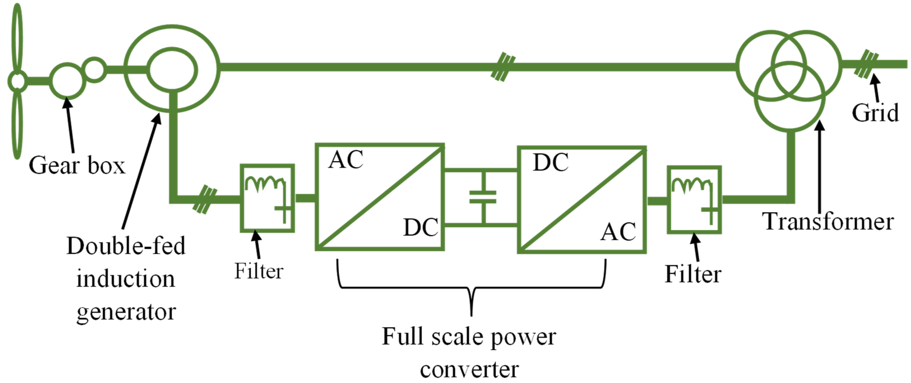
2.3. Doubly Fed Induction Generators (DFIG)

Holding about half the market share, the DFIG, however old, is one of the most popular generators used in wind energy conversion systems [37,38]. True to its name, the DFIG has both stator and rotor windings feeding the grid. Its architecture is basically that of a WRIG but with a rotor-connected partial-scale power converter that replaces the external variable resistor and feeds rotor-dissipated power back to the grid as shown in Figure 5 [29,39]. By controlling rotor frequency, the power converter controls the rotor speed. This makes for a wide variable-speed range control (typically 30% of synchronous speed) [32,40]. The 25–30%-rated power converter provides a cost-effective means of reactive power compensation and seamless grid connection, hence the DFIG’s popularity. General Electric’s GE 4.8-158 (4.8 MW) [14] and Gamesa’s G90 (2 MW) [41] represent some examples of wind turbines that use DFIGs.
During operation, the rotor’s magnetic field will rotate at a speed proportional to the frequency of the AC signal applied to the rotor windings via the rotor side power converter. This rotating field created in the rotor then links the stator windings, hence inducing an EMF in them through which a current later develops a stator rotating magnetic field flows. The frequency of the stator is constant regardless of the variation of speed in the rotor, but for this to be achieved, the frequency of the AC signal that is fed to the rotor windings needs to be adjusted. It is this control mechanism that allows DFIGs to operate at a wide variable speed range.
The popularity of DFIGs in wind turbines has led to the design of models that allow for continuity in operation when faults are experienced on the power system (Fault Ride through or FRT) [39,42]. However, the partial-scale converter makes the FRT capability somewhat trivial as only a small fraction of the power generated can be controlled. Additionally, regular maintenance would be required on the expensive and weighty gearbox as well as on the frail brushes which have an average lifespan of about 12 months [27]. These are notable factors limiting the DFIG’s application in offshore WECS. Major players in the machine manufacturing industry such a Vestas, Nordex, General Electric, Gamesa, Ming Yang and Guodian United Power have also played a major role in commercializing three-stage gearbox DFIGs for an average power range of 1.5 MW to 3.3 MW [31].

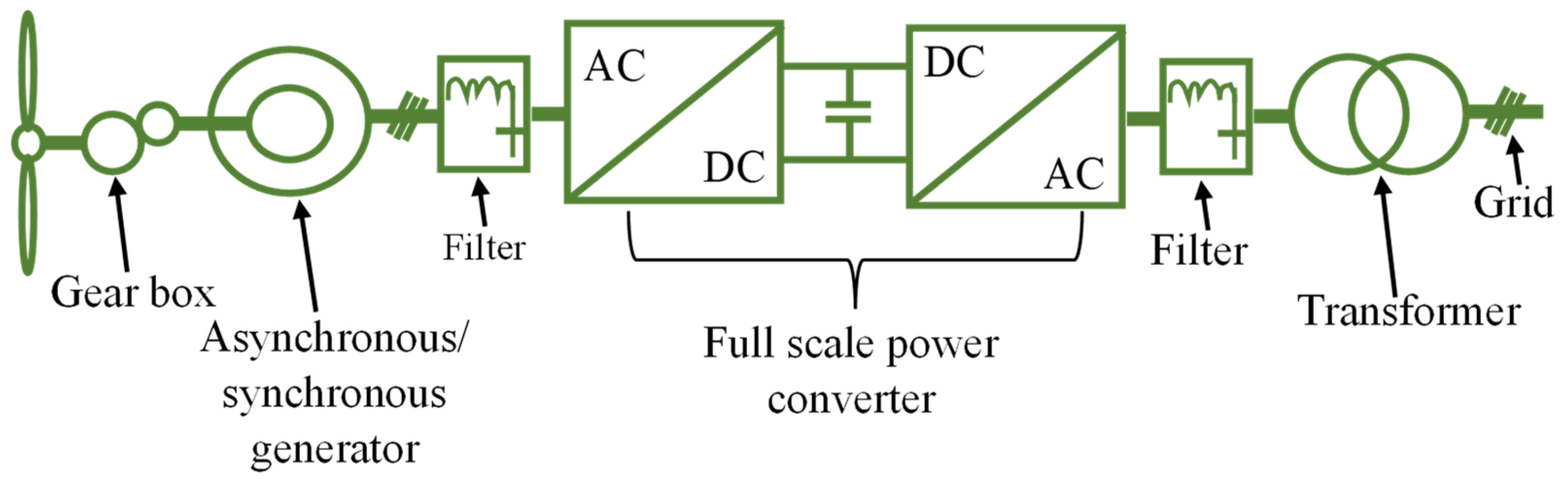
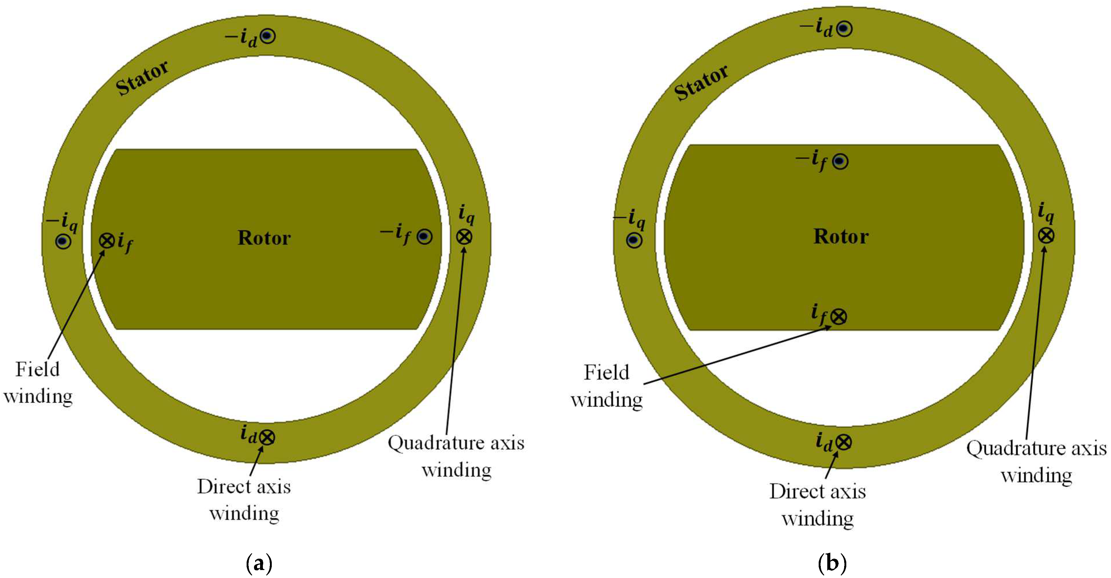
2.4. Electrically Excited Synchronous Generators (EESG)

In a bid to eliminate the maintenance requirement and failures of the gearbox, gearless drivetrain WECS have been proposed. The EESG is an example of this low-speed (10–25 rpm), high-torque salient-multipole solution [43]. With high torque requirements comes the need for increased rotor diameter to accommodate a multipole structure. This is responsible for a bulkier and heavier machine when compared with the PMSG. EESG’s architecture consists of an externally excited rotor field and a three-phase wound stator. A full-scale power converter as shown in Figure 6 is usually employed in EESGs, which allows for total grid isolation. Additionally, this ensures reactive power compensation, smooth grid connection, effective FRT and near-perfect speed variation capabilities [27].
Besides being an expensive solution, the losses accrued due to the use of a full-scale converter are significant since all the power generated must be transported through it. This impinges on the EESG’s efficiency. Additionally, EESGs require slip rings and brushes or a constant low frequency (500 Hz) rotating transformer for rotor excitation (about 3% of rated power), thus increasing the cost of maintenance [44]. The use of field windings increases copper usage, which contributes towards the machine’s heaviness and reduced efficiency. This makes EESGs a less popular option for large offshore wind energy installations [45]. Enercon is a popular manufacturer of wind turbines with EESGs. Examples are E126 (7.5 MW) [46] and E-82-E3 (3 MW) [47] and E-112 (4.5 MW) [48].
Figure 6. EESG with full-scale power converter [46].
Wind 02 00023 g006

3. Non-Conventional Non-PM Electrical Machines

“Non-conventional” refers to emerging generator types that have stimulated research by possessing characteristics that show viability in wind turbine applications. “Non-PM” applies to generator topologies that do not use any kind of permanent magnets for flux linkage or excitation. In retrospect, the study of non-PM generators is necessary because it improves the array of viable alternatives in the electric machine mix. Equally important is its potential to break global dependability on China for the supply of rare-earth metals—an important raw material in the energy-dense NdFeB-based PMs—and thus prevent potent risks of demand and supply crises. Additionally, PM flux is non-adjustable, and the cheaper ferrite magnets suffer risk of demagnetization. Lastly, with regards to machine design, a solely active stator and a brushless robust rotor are desirable features for improving system maintainability, reliability and flexibility.
In this section, emerging (non-conventional) non-PM machines are considered. Their potential in wind energy application is explored by discussing their torque development philosophy, maintainability and controllability as well as current constraints to adoption. Worthy of note is the fact that the undermentioned non-conventional generator topologies are still in various development phases and not yet commercialised [14,42].

3.1. Reluctance Synchronous Machine (RSM)

A reluctance synchronous machine is a type of variable reluctance machine being used for a wide range of power applications including in wind turbines. With no windings on its rotor construction, copper losses are eliminated, and the size of the cooling fan reduced, meaning that friction and windage losses are also reduced. A number of reasons are responsible for RSG’s popularity; the efficiency of this machine is high, and its construction is simple and rugged with a comparatively reduced physical size, thereby making a case for cost effectiveness [19,49,50,51]. Its stator construction is like that of the induction machine, but the rotor is just an iron core with distributed anisotropy as a result of barriers in flux and its optimized bridged shape. For improved rotor robustness, laminations can be aligned using non-magnetic, non-conductive studs, and high-power density and efficiency would be attained if the stator poles were segmented and constructed with no overlapping winding slots.
The development of the reluctance synchronous machines (RSMs) has been long and well documented [52,53,54,55]. Its performance (such as torque density and efficiency) has been to found to be on par with, and sometimes even better than, the induction machines’ (IMs) [56,57,58,59,60,61]. Standard designs show negligible passive-rotor losses, and with the eradication of slip rings and brushes, the RSM offers similar robustness compared to the IM. In comparison with the PMSG, which displays a higher efficiency and power factor, the absence of rare-earth metals makes the RSM an attractive and cost-effective solution.
Multivariable design optimisations abound for the RSM, all geared towards achieving PM-comparable machine performance. Dipenaar investigated the consequences of eradicating the complex rotor structures (usually constituted of multiple flux barriers (MFB)—a structural stability concern—or axial laminations) of RSG by using, first, a simplistic salient pole (based on similar design parameters of machines evaluated in [62] and [63] and, later on, a split-pole rotor design for a 5 MW power-level, medium-speed (a compromise between reliability and mass) drive design [64]. This split-pole setup (an MFB redesign with much less complexity) yielded a high efficiency of 98% and a less-than-5% torque ripple achieved through rotor skewing and a fractional slot winding (as demonstrated in ref. [65]). Also worthy of note was the 20% betterment in power factor (0.65) achieved on the split-pole rotor in comparison with the salient pole rotor. Similarly, the rotor and stator of a 5.5 kW power-level high speed (1500 r/min) RSM was optimised with an objective to maximise its drive system efficiency (93.2%; a 3.5% superiority in comparison with an IE3-classed induction machine of similar design parameters), improve power factor and, as a result, reduce inverter losses. It was noted that an optimisation algorithm aimed at inverter losses minimisation automatically resulted in a power factor (0.79) improvement [66].
While rotor skewing results in torque ripple reduction, it also decreases average torque. Thus, an optimal skewing angle must be sought that presents a reasonable trade-off between average torque and torque ripple with the objective of better overall machine performance. Though one-slot-pitch is purported as conventional [17,20], it may be safe to infer that skewing angle is largely dependent on machine performance objectives as recent optimization results have been achieved with other skewing angles [10,19].
Notable downsides of the RSG include poor power factor and the challenges of establishing adequate system control. However, due to its reasonable performance, there has been ongoing research to forestall these shortcomings. The RSG’s easy self-excitation, using capacitor banks, makes it a valuable option when deploying power systems in isolated locations [51,67].

3.1.1. Torque Ripple

The operation of RSMs is based on reluctance torque where the generation of torque is as a result of the difference in permeance of the d- and q-axes. Thus, the interaction between stator-current-induced magnetic flux and rotor permeance harmonics create torque ripple. Careful design considerations are necessary to prevent torque ripples from significantly affecting the RSM performance. The effects of skewing rotors with multiple flux barriers have been examined using a multi-objective FEM [68]. This showed that careful selection of a skewing angle, for a continuous and discrete skew, shows a significant reduction in torque ripple albeit slightly compromising the average torque. Another finding shows a direct relationship between the stator slot size and torque ripple and confirms less ripple for cylindrical stators as opposed to salient-pole stators [69].
Several publications have examined general design parameters necessary for reducing torque ripple [70,71]. Furthermore, other studies examined the effects of rotor structures (with respect to its width, position and shape of flux barrier) on torque ripple and have proffered optimized rotor solutions [72,73,74,75].

3.1.2. Power Factor

A weighted factor relationship (independent of flux barrier, pole number and power level) has been established between the average torque and the power factor of a RSG [76]. This ensures that average torque and power factor could be estimated, with up to 95% accuracy, for any specific weight point of the generator. This enables designers to vary the weighted factor to achieve the desired power factor. Another study relates the power factor with the current space phasor angle Φ and shows maximum power factor values when the current angle is between 72° and 75°. However, the maximum power factor occurs at the minimum kVA value [77]. The assisted and compensated RSM (known as ARSM and CRSM) are two interesting topologies [78]. As shown in Figure 7, they have round rotors with windings on the d- and q-axes, differentiating them. Flux generated in the d-axis windings of the ARSM minimizes the current requirement of the d-axis as opposed to lowering q-axis flux linkage. The q-axis rotor windings of the CRSM perform the function of permanent magnets in PM-assisted synchronous reluctance machines by providing excitation. However, in principle, the ARSM and CRSM are wound-rotor machines and introduce the maintenance requirements associated with slip rings and brushes.

3.1.3. Control

RSGs are usually difficult to control judging from the non-linearity of the flux linkages. Some theories favour a forward-thinking, saliency-based sensorless control that explores the anisotropic nature of reluctance machines’ flux patterns [79,80]. However, most synchronous machine operations require parameter estimation and hardware for adequate control. Generally, a number of control schemes have been proposed: the direct torque control or torque vector control explored in [81,82], lauded for its ruggedness and swift response but possessing torque ripples [83,84], and the contrasting “traditional” vector control discussed in [85,86,87], merited for its torque response and efficiency [79,88].

3.2. DC-Excited Vernier Reluctance Machine (DC-VRM)

The Vernier reluctance machine (VRM) is another type of reluctance machine that is robust, having a simple structure and a high-torque density. It operates with the vernier effect where a minutely small rotor displacement produces large permeance axes displacement, thus generating more torque as the rotor speed slips from the rotating field speed. This makes it suitable for low-speed wind power applications [89]. Like the other reluctance machines, the VRM has more rotor poles as compared to its stator poles for the vernier effect to be possible [90]. Several models for more accurate analysis of the VRM have been suggested.
To succeed with the non-PM variants, their stator PMs are replaced with stator windings that allow the flexibility of flux control of the machine. Hence, procedures for formulating stator/rotor pole combinations, matching winding configurations and winding factors of the DC-excited VRM (DC-VRM), were developed in [91]. Here, the static state performance criteria were established for back-EMF, inductance, cogging torque, static torque, torque ripple and unbalanced magnetic force (UMF). This was made possible by utilizing a simple rotor pole-pairing technique. Additionally, a general FMM model for efficient and accurate parameter analysis of the DC-VRM was proposed in and compared with a similar wound-field FMM [92]. Another analysis on DC-VRMs was performed in [93] with the quest to improve its power factor. This DC-VRM is stator-DC winding excited via concentrated windings that allow flexibility in a wide speed range. Talking of the stator concentrated windings of DC-VRMs, ref. [94] compares various novel stator field winding configurations in a bid to evaluate higher torque density and back electromotive force.
Torque ripple, a composition of cogging and pulsating torque, is a notable weakness of VRMs. Various approaches for ripple reduction have been proposed in [95]. These include variations of air gap length, stepped rotor skewing and rotor tooth-chamfering. Optimized benchmark designs (OBDs) based on torque ripple reduction using rotor pole pairing for direct-drive wind power generators were investigated in [96]. Using a 15 kW DC-VRM as a case study, a reduction of more than 50% was observed at a pole pairing ratio of 0.8. However, torque ripple minimization techniques for DC-VRMs are a compromise of a slightly reducing the average torque.

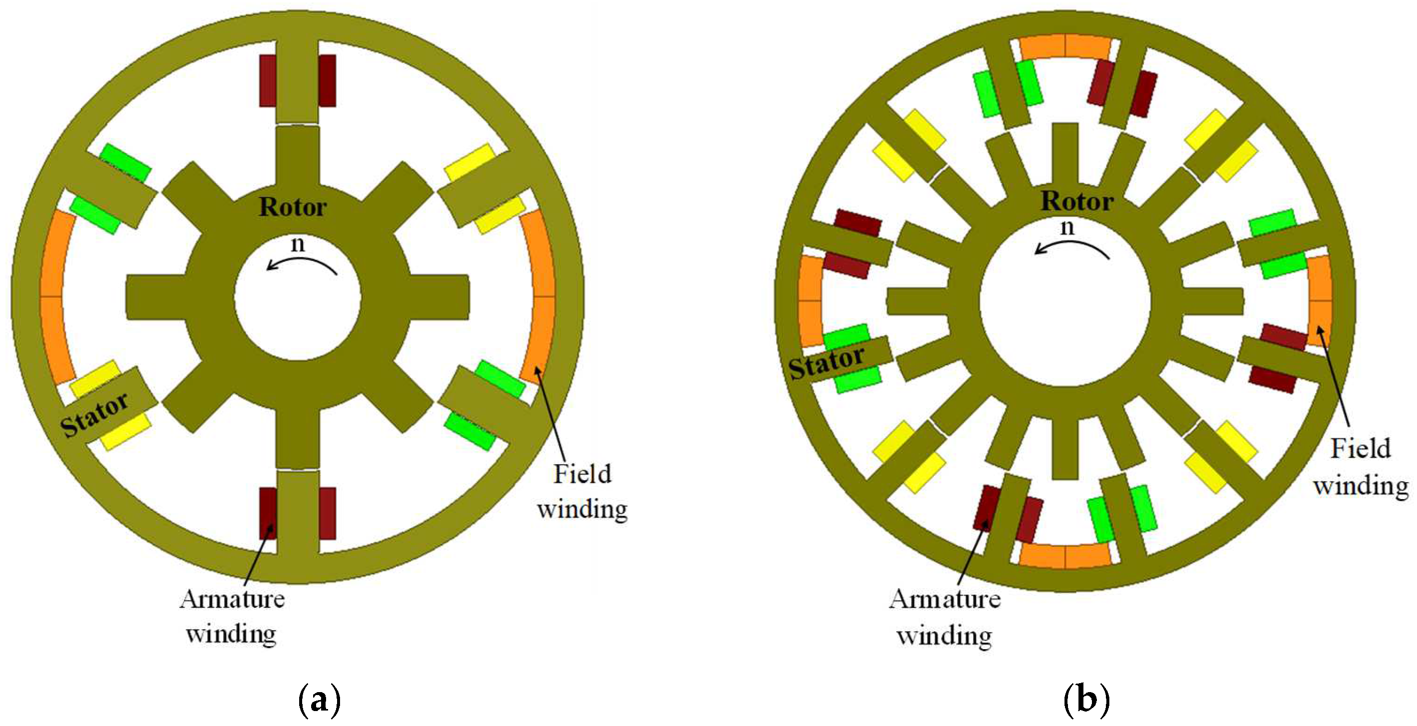
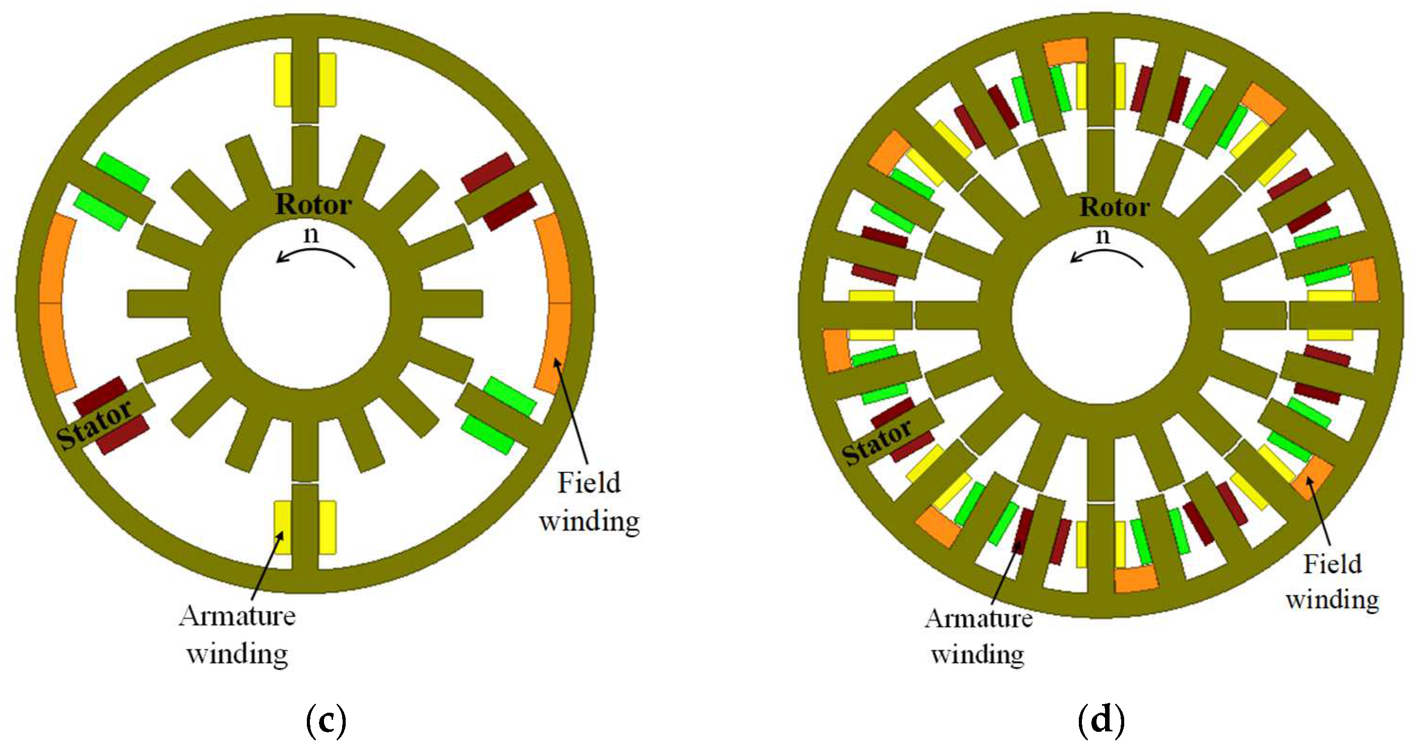
3.3. Wound-Field Flux Switching Machine (WF-FSM)

FSMs can be the PM type (PM-FSM) or field-wound (WF-FSM) [97]. Rhetorically, the latter is of our main interest because it does not use PMs but only windings for its field. The flux switching mechanism has a fundamental principle of using the salient rotor for field modulation while producing flux-linkage polarity switching in the armature windings. Hence, reluctance is minimized by aligning the stator and rotor poles, with an increased inductance path, and vice versa [98,99]. Once again, the rotor of the FSM has no windings or PMs but just a laminated iron core. This allows for a simple and rugged rotor construction that is robust and reliable even when running at very high speeds. The rotor has no copper loss and reduced eddy current losses, allowing it to be cooler and only requiring small fans, hence reducing the size of the machine for a given power output [100,101]. The bearings also run cooler, and this prolongs their lifespan. The stator windings are concentrated, therefore making their construction and cooling simple. Its phases are independent of each other; hence, if one is faulty, the others are not affected, but would run with two phases only at a reduced power output. Faults being isolated mean easy troubleshooting and less severe damage to the machine.
New manufacturing technology is needed for FSM because their technology has not yet matured fully. Their recent emergence makes them hard to design, while special power converters are needed for precise control and are still emerging. The power density and peak efficiency of this machine is not optimal, and due to its double saliency, the noise produced is difficult to control. To this end, high-torque ripples create vibrations within the machine.
In an optimisation study, a low-power, high speed (1500 r/min), three-phase, dual rotor FSG with a capability for a constant DC-voltage output over a wide speed ranges and load currents was developed and suited for DC microgrids [102]. The dual rotor configuration presents a way to use non-overlapping concentrated coils on both field and armature windings (as opposed to distributed windings), resulting in less end-winding utilisation and ultimately copper loss reduction [103]. Equally, a higher power density objective justified the use of a more-than-one phase system as explained in [24]. A rotor and stator pole-arc optimisation was performed for back EMF maximisation and torque ripple minimisation and a 12-degree pole arc selected for both stator and rotor as this presented the best compromise for the abovementioned objectives as well as made for easy manufacturability.
A new generator variant, using high temperature superconducting (HTS) material, has been tested on FSMs. Exploited mainly for its excellent power density and efficiency characteristics, the HTS opens up an opportunity for direct-drive WECS [104,105]. A constant-output-voltage HTS-FSM that employs BSCCO-2223 HTS tape was studied in [106] in comparison with a similarly sized PM-FSM. The results of this study showed a no-load EMF of the HTS-FSM being 1.49 times greater than the PM-FSM. Equally, the power density of the HTS-FSM was found to be 49% better than the PM-FSM. Equally, in the quest for better electromagnetic performance as well as cost and weight effectiveness, two variants (single- and double-polarity) of a high-power, double-stator, direct-drive HTS offshore-classed wind generator was analysed in [107]. While both machines produced similar average torque waveforms (11 MNm), the double-polarity variant provided better cost and materials savings (about $33,200).
An experimental test using a 10 kW WF-FSM was discussed in [18] with the aim of detailing manufacturing procedures for achieving simple industrial-scale designs for geared medium-speed wind generator applications. Additionally, two design variants of the WF-FSM were evaluated to show their potentials in locally developed wind power technologies in [108]. The study evaluates the efficiency, torque and power factor improvements by different arrangements of armature and field coils, shown in Figure 8. Of the two designs in Figure 8, D-II showed improved performance characteristics over D-I.
In reference [109], a comparative study on the WF-FSM with another non-conventional wound-rotor synchronous machine (WRSM) for wind generator application was undertaken. The WRSM with a nonclassical non-overlap winding is designed, optimised and compared to the WF-FSM at 3 MW geared medium-speed wind power generation. At such power levels and wind generator drivetrain, both machines are proof that they are capable of utility-scale wind power. The study is experimentally validated with small kW prototypes based on converter-fed and direct-grid connected wind power generation. Other experimental studies on the WF-FSM have been undertaken in [18] and [110] for wind power generator performance.

3.4. Double-Salient DC Machine (DSDCM)

The DSDCM is the non-PM variant of the well-established DSPM and, as such, shares a similar architecture and operating philosophy [20,111,112]. As a hybrid of the SRM, it characteristically inherits the benefits of the low cost, simplicity and reliability. Since it has DC-excited field windings, its flux can be regulated to provide enhanced efficiency over the variable speed range, which may obliterate the need for position sensors and power converters. This makes it a possible choice for direct-drive wind turbine applications [113].
A 6/4-pole topology requiring a stator–rotor pole ratio of 1.5 is the traditional design of the three-phase DSDCM—a so-called basic unit. However, this topology has been questioned for high-power direct-drive applications since they would require increased pole pairs (6k/4k where k is any positive integer) to enhance power density. The use of the basic unit topology would mean narrower stator slots and the increased use of copper leading, to obvious disadvantages of increased reactance and winding losses. Thus, with an alternative 3k/4k topology proposed in [114], a 24/32-pole topology for low speed wind energy applications was evaluated against a 48/32-pole traditional topology for efficiency, power density and voltage ripple and showed good performance. Similarly, in [110], a novel 6k/4Nk topology (where N is any integer except one and multiples of three) was proposed and three variants evaluated as in Figure 9, showing the superior performance of a lower cogging torque, higher power density and higher efficiency when compared with traditional designs.
For better system reliability and resilience, several interesting multiphase fault-tolerant variants of the DSDCM have been discussed in [23]. These variants may operate without the use of position sensors and power electronic converters and boast of a continuous power quality supply even in the event of phase faults.

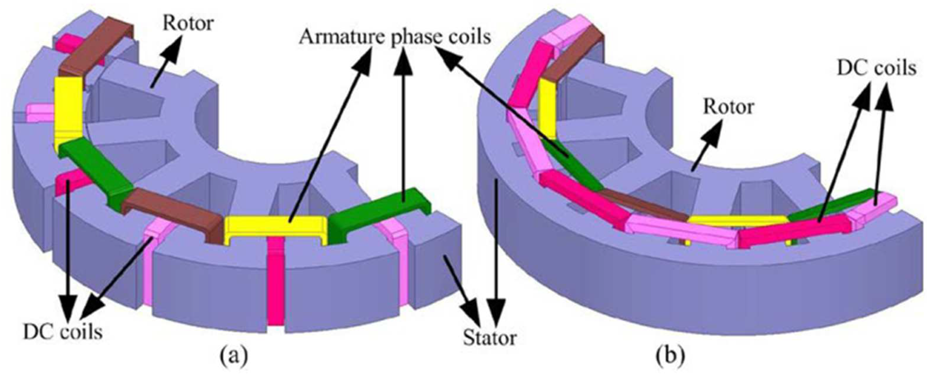
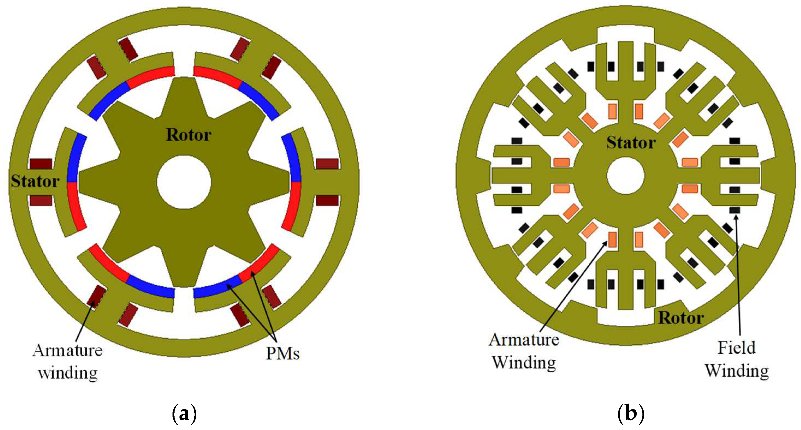
3.5. DC-Field Excited Flux Reversal Machine (DC-FRM)

Flux reversal machines are yet another modification of the SRM borne out of the quest for improved torque density, lower pulsating torque and better controllability [115]. The DC-FRM architecture is achieved by substituting the PMs in PM-FRM with DC-field excitation. The stator of the FRM has both DC-field and armature windings mounted on it. The armature windings are concentrated and wound on each stator pole, while the DC-field windings are arranged to mimic the PM-FRM so that they provide a similar flux-linkage polarity reversal as the PM-FRM does.
A simple, rugged and robust mechanical construction of the rotor is observed in the DC-FRM, where neither windings nor field excitation are present. This allows for rotor reliability, less maintenance and suitability for low-speed direct-drive applications such as in wind systems. The absence of windings also means that copper losses are omitted; hence, the efficiency of the machine is high. The light weight of the FRM rotor leads to their inertia upon rotation being small, therefore allowing a quicker change of rotor speed with respect to time. Due to the design isolation between its phases, it exhibits fault-tolerant characteristics [116].
The non-uniformity of the airgap across the DC-FRM construction translates to the development of a cogging torque during machine operation. This results in a deterioration of the machine’s performance and shows up as noise and vibrations especially at low operating speeds [117]. Figure 10a shows a basic cross-section of a 6/8-pole PM-FRM.
A unique four-phase DC-FRM with its architecture designed to mimic the PM-FRM was proposed and developed in [24] for wind power generation as shown in Figure 10b. Its performance was evaluated against two variants of the PM-FRM topology with similar configurations to ensure fair and equitable comparison. The results show a more superior power density output from the PM topologies, justifying the preferred use of the more energy-dense magnets. However, a more holistic comparison involving flux controllability and cost effectiveness would reveal the merits of the DC-FRM as indicated in Table 1.
While flux controllability (which enables the generation of a constant voltage output over variable speed range) and cost effectiveness represent big wins for the DC-FRM, it inherits a number of characteristic flaws namely, high cogging torque [117] and low power factor [118].

3.6. Brushless Doubly-Fed Machines

It should be mentioned that similar to the DFIGs, are the so-called brushless doubly fed induction machines (BDFIMs), which avail a higher reliability compared to the former, especially for wind power generation. They do not require slip rings and brushes, hence qualifying them as brushless wound-field machines. A state-of-the-art overview undertaken in [119] highlights their different design topologies and evolutionary studies. BDFIMs have two stator windings with different pole numbers and operating frequencies, which cross-magnetize with the rotor to achieve synchronous operation. Recent developments as highlighted in [119] show that BDFIMs are yet to attain commercial scale, but some attempts are being made on their prospects for industrial scale wind generators.
Moreover, there are brushless doubly fed reluctance machine (BDFRMs) that are in possession of a reluctance rotor but two stator windings. Their rotors exist in three main topologies—simple salient pole, multi-layer flux barrier and axially laminated design of which a hybrid design can be formed among any of the three [120]. Due to cascaded stator winding design, BDFRM enjoys different operating modes such as simple induction, cascade induction, single-fed synchronous, doubly-fed asynchronous and doubly-fed synchronous modes. The main challenge of BDFRMs is relatively low-torque density and efficiency compared to DFIGs; however, this has not prevented their foray into wind power generation [120].

4. Comparative Analysis of Non-Conventional Non-PM Electrical Machines

The quantitative and qualitative analysis of the various non-conventional generators are studied in this section to provide an inference on their suitability for WECS. Table 2 is a summary of key performance parameters investigated among the different wind generators highlighted in the preceding section while using the conventional small- and large-scale power PMSGs reported in [90,121] as benchmarks. It also shows areas of strength and weakness. It is noteworthy to mention that the characteristic parameters are for machines tested over kW and MW power ranges and, at most, constrained to experimental results. As such, the data presented, at best, estimates the empirical behaviour of these machines as opposed to providing articulate industrial valuation.
A glance at Table 2 immediately reveals the cost benefits of these novel generator types at reasonable torque per generator litre performance. With robust rotors and absence of PMs, these cost savings are expected both in terms of operational and capital costs. Another interesting outcome is the dominant speed of their drivetrains. As shown, these are mostly in the low- and medium-speed range, thus, requiring fewer or no gear stages. Thus, in addition to being brushless, the recurring maintenance costs attributed to higher stage geared systems are either minimised or eliminated.
While there are as yet no clear-cut favourites among the proposed brushless wound-field generators, since each configuration has its merits and demerits, the emerging low-speed characteristics necessitate the need for high-torque density generators. As discussed, direct-drive generators are usually larger, denser and more expensive to install than their gearbox-driven counterparts. The mainstream adoption of the direct-drive systems would depend on modifications to this system in a bid to drive down costs while upholding the generator performance—something that already appears feasible based on certain performance data in Table 2.
The sub-optimal power factor, torque ripple and efficiency obtainable from most of these non-PM non-conventional generator types are the main concerns for researchers. It is on this basis that more studies are expected in the coming years to tackle these challenges and make the proposed wind generator variants commercially viable.

5. Conclusions

In this study, different conventional and non-conventional wind generators have been examined. It is understood that the direct-drive PM wind generators are the current industrial mainstay due to their high torque density and efficiency performance, but they are faced with high costs and demagnetization risks. Meanwhile, non-PM generator candidates providing low cost and variable flux options are being considered over PM wind generator variants. However, non-PM excited generators are limited by their classical rotor field-excited windings and presence of slip rings and brushes which lower their efficiency and reliability. On the other hand, stator-mounted wound-field FMMs, which are brushless in nature due to a robust rotor design, are beginning to trend. The identifiable brushless wound-field wind generator candidates examined in this study, all of which are yet to be commercialized, are RSM, DC-VRM, WF-FSM, DSDCM and DC-FRM, among others. Moreover, these machines exercise the so-called robust rotor topology, meaning that their wound-field excitation is not necessarily propagated using slip rings and brushes.
In this study, quantitative and qualitative comparative assessments on these new generation wind generators, though still at preliminary design stages, are conducted. For example, at small (15 kW) power levels, it is seen that the torque per volume of a DC-VRM operating at 200 r/min is 17.4 kNm/m3, which is reasonable when compared to a conventional PMSG operating at 150 r/min, which yielded 24 kNm/m3. The predicted torque density of the DC-VRM is because it operates on the flux modulation principle and as such, can provide high torque capability based on magnetic gearing effects [15,16]. Meanwhile, it is observed that the torque ripple of the DC-VRM is 2.5 times that of the PMSG, and this is usually the Achilles’ heel of FMMs because of their double-salient design. Additionally, due to high saturation effects and cross-magnetic fields of the stator-mounted field and armature windings, the power factor of the DC-VRM is poorer, as seen in this case. It is not surprising that the presence of field windings, among other things, also meant that the efficiency of the DC-VRM is much lower (87.4%) compared to that of the PMSG (94.4%). In addition, the speed regimes of the studied brushless wound-field wind generators are suggestive of ranges in the low- and medium-speed wind generator drivetrains, a trend that could be somehow associated with their characteristic high pole numbers.
In general, the highlighted non-conventional non-PM wind generators show promise in terms of low-cost and high-torque density performance. However, issues relating to torque ripple, power factor and efficiency performance are some of the notable challenges driving new research while aiming to position these non-PM FMMs as viable wind generator technologies for futuristic high-power direct-drive wind power generation systems. The highlight of the discussions on these emerging non-PM wind generators is that they offer a low-cost, low maintenance and high-torque density solution.

Author Contributions

Conceptualization, U.B.A., O.P. and K.K.; methodology, U.B.A., D.U., K.K. and O.P.; software, U.B.A., O.P. and J.L.M.; validation, U.B.A., O.P. and J.L.M.; formal analysis, D.U., K.K. and U.B.A.; investigation, D.U., K.K. and U.B.A.; resources, U.B.A., O.P. and J.L.M.; data curation, D.U., K.K. and U.B.A.; writing—original draft preparation, D.U., K.K. and U.B.A.; writing—review and editing, U.B.A., O.P. and J.L.M.; visualization, D.U. and U.B.A.; supervision, U.B.A., O.P. and J.L.M.; project administration, U.B.A.; funding acquisition, U.B.A., O.P. and J.L.M. All authors have read and agreed to the published version of the manuscript.

Funding

This research work is supported in part by the Eskom Power Plant Engineering Institute (EPPEI) Renewable Energy Programme, Stellenbosch University, South Africa.

Institutional Review Board Statement

Not applicable.

Informed Consent Statement

Not applicable.

Data Availability Statement

The data for this study is presently archived with the third author, U.B.A., and can be made available.

Acknowledgments

U.B.A. is grateful to Hillary C. Idoko, Department of Electrical Engineering, Tshwane University of Technology, South Africa, for redrawing some of the figures used in this study.

Conflicts of Interest

The authors declare no conflict of interest.

Abbreviations

AFDSMAxial Flux Doubly Salient Machine
ARSMAssisted Reluctance Synchronous Machine
ASPAsymmetric Stator Pole
BDFIMBrushless Doubly-Fed Induction Machines
BDFRMBrushless Doubly-Fed Reluctance Machines
BLACBrushless Alternating Current
BLDCBrushless Direct Current
BSMMBrushless Stator Mounted Machine
CPSRConstant Power Speed Range
CRSMCompensated Reluctance Synchronous Machine
DCDirect Current
DFIGDoubly Fed Induction Generator
DSDCMDouble-Salient Direct Current Machine
DSMDouble-Salient Machine
DSPMDouble-Salient Permanent Magnet Machine
EESGElectrically Excited Synchronous Generator
EMFElectromotive Force
FEMFinite Element Method
FMMFlux Modulation Machine
FRMFlux Reversal Machine
FRTFault Ride Through
FSGFlux Switching Generator
FSMFlux Switching Machine
HSHigh Speed
HTSHigh Temperature Superconducting
HVDCHigh Voltage Direct Current
kWKilowatt
LCOELevelized Cost of Energy
MFBMultiple Flux Barriers
MWMegawatt
OBDOptimized Benchmark Design
PMPermanent Magnet
PMSGPermanent Magnet Synchronous Generator
RSGReluctance Synchronous Generator
RSMReluctance Synchronous Machine
SCIGSquirrel Cage Induction Generator
SRMSwitched Reluctance Machine
UMFUnbalanced Magnetic Force
USDUS Dollar
VRMVernier Reluctance Machine
WECSWind Energy Conversion System
WFWound Field
WRIGWound Rotor Induction Generator
WRSMWound Rotor Synchronous Machine

References

  1. REN21. Renewables 2021 Global Status Report; REN21 Secretariat: Paris, France, 2021; ISBN 978-3-948393-03-8. [Google Scholar]
  2. Mantashe, S.G. Integrated Resource Plan 2019. Department of Mineral Resource and Energy, South Africa, Pretoria. 17 October 2019. Available online: http://www.energy.gov.za/IRP/2019/IRP-2019.pdf (accessed on 31 March 2022).
  3. Department of Energy. The South African Energy Sector Report 2021; Department of Mineral Resources & Energy, South Africa, 2022; ISBN 978-1-920435-18-9. Available online: http://www.energy.gov.za/files/media/explained/2021-South-African-Energy-Sector-Report.pdf (accessed on 31 March 2022).
  4. Shaun, I. Wind Energy and Its Application. Available online: https://www.yourarticlelibrary.com/paragraphs/wind-energy-and-its-application/47799 (accessed on 31 March 2022).
  5. Ragheb, M. Modern Wind Generators; University of Illinois: Champaign, IL, USA, 2019. [Google Scholar]
  6. Moore, S.K. Rough Seas for the Superconducting Wind Turbine: To Keep Offshore Turbines Light, Engineers Look beyond Superconductors to a New Permanent-Magnet Tech. IEEE Spectr. 2018, 55, 32–39. [Google Scholar] [CrossRef]
  7. De Vries, E. Wind Turbine Drive Systems: A Commercial Overview; Woodhead Publishing Limited: Sawston, UK, 2013; ISBN 9781845697839. [Google Scholar]
  8. NREL. Advanced Wind Turbine Drivetrain Concepts. Work. Rep. 2010, 1–31. Available online: https://www.nrel.gov/docs/fy11osti/50043.pdf (accessed on 31 March 2022).
  9. Pavel, C.C.; Lacal-Arántegui, R.; Marmier, A.; Schüler, D.; Tzimas, E.; Buchert, M.; Jenseit, W.; Blagoeva, D. Substitution Strategies for Reducing the Use of Rare Earths in Wind Turbines. Resour. Policy 2017, 52, 349–357. [Google Scholar] [CrossRef]
  10. Chen, H.; Zuo, Y.; Chau, K.T.; Zhao, W.; Lee, C.H.T. Modern Electric Machines and Drives for Wind Power Generation: A Review of Opportunities and Challenges. IET Renew. Power Gener. 2021, 15, 1864–1887. [Google Scholar] [CrossRef]
  11. Tahanian, H.; Aliahmadi, M.; Faiz, J. Ferrite Permanent Magnets in Electrical Machines: Opportunities and Challenges of a Non-Rare-Earth Alternative. IEEE Trans. Magn. 2020, 56, 1–20. [Google Scholar] [CrossRef]
  12. Ishikawa, T.; Igarashi, N.; Kurita, N. Failure Diagnosis for Demagnetization in Interior Permanent Magnet Synchronous Motors. Int. J. Rotating Mach. 2017, 2017, 2716814. [Google Scholar] [CrossRef] [Green Version]
  13. Watson, S.; Moro, A.; Reis, V.; Baniotopoulos, C.; Barth, S.; Bartoli, G.; Bauer, F.; Boelman, E.; Bosse, D.; Cherubini, A.; et al. Future Emerging Technologies in the Wind Power Sector: A European Perspective. Renew. Sustain. Energy Rev. 2019, 113, 109270. [Google Scholar] [CrossRef]
  14. Bensalah, A.; Benhamida, M.A.; Barakat, G.; Amara, Y. Large Wind Turbine Generators: State-of-the-Art Review. In Proceedings of the 2018 XIII International Conference on Electrical Machines (ICEM), Alexandroupoli, Greece, 3–6 September 2018; pp. 2205–2211. [Google Scholar] [CrossRef]
  15. Li, D.; Qu, R.; Li, J. Topologies and Analysis of Flux-Modulation Machines. In Proceedings of the ECCE 2015: IEEE Energy Conversion Congress and Exposition, Montreal, QC, Canada, 20–24 September 2015; pp. 2153–2160. [Google Scholar] [CrossRef]
  16. Qu, R.; Zhou, Y.; Li, D. Milestones, hotspots and trends in the development of electric machines. iEnergy 2022, 1, 88–99. [Google Scholar] [CrossRef]
  17. Cheng, M.; Han, P.; Du, Y.; Wen, H.; Li, X. A Tutorial on General Air-Gap Field Modulation Theory for Electric Machines. IEEE J. Emerg. Sel. Top. Power Electron. 2021, 10, 1712–1732. [Google Scholar] [CrossRef]
  18. Akuru, U.B.; Kamper, M.J. Novel Experimentation of a 10 KW Geared Medium-Speed Wound-Field Flux Switching Wind Generator Drive. In Proceedings of the 2018 IEEE Energy Conversion Congress and Exposition (ECCE), Portland, OR, USA, 23–27 September 2018; pp. 6492–6498. [Google Scholar]
  19. Szabo, L. A Survey on Modular Variable Reluctance Generators for Small Wind Turbines. IEEE Trans. Ind. Appl. 2019, 55, 2548–2557. [Google Scholar] [CrossRef]
  20. Liao, Y.; Liang, F.; Lipo, T.A. A Novel Permanent Magnet Motor with Doubly Salient Structure. IEEE Trans. Ind. Appl. 1995, 31, 1069–1078. [Google Scholar] [CrossRef]
  21. Deodhar, R.P.; Andersson, S.; Boldea, I.; Miller, T.J.E. The Flux-Reversal Machine: A New Brushless Doubly-Salient Permanent-Magnet Machine. IEEE Trans. Ind. Appl. 1997, 33, 925–934. [Google Scholar] [CrossRef]
  22. Hoang, E.; Ben-Ahmed, A.H.; Lucidarme, J. Switching Flux Permanent Magnet Poly-Phased Synchronous Machines. In Proceedings of the 7th European Conference on Power Electronics and Applications, Trondheim, Norway, 8–10 September 1997; Volume 3, pp. 903–908. [Google Scholar]
  23. Zhu, D.; Qiu, X.; Zhou, N.; Yan, Y. A Novel Five Phase Fault Tolerant Doubly Salient Electromagnetic Generator for Direct Driven Wind Turbine. In Proceedings of the 2008 International Conference on Electrical Machines and Systems, Wuhan, China, 17–20 October 2008; pp. 2418–2422. [Google Scholar]
  24. Lee, C.H.T.; Chau, K.T.; Liu, C. Design and Analysis of a Cost-Effective Magnetless Multiphase Flux-Reversal DC-Field Machine for Wind Power Generation. IEEE Trans. Energy Convers. 2015, 30, 1565–1573. [Google Scholar] [CrossRef] [Green Version]
  25. Polinder, H.; Van Der Pijl, F.F.A.; De Vilder, G.J.; Tavner, P.J. Comparison of Direct-Drive and Geared Generator Concepts for Wind Turbines. IEEE Trans. Energy Convers. 2006, 21, 725–733. [Google Scholar] [CrossRef] [Green Version]
  26. Duong, M.Q.; Grimaccia, F.; Leva, S.; Mussetta, M.; Ogliari, E. Pitch Angle Control Using Hybrid Controller for All Operating Regions of SCIG Wind Turbine System. Renew. Energy 2014, 70, 197–203. [Google Scholar] [CrossRef]
  27. Yaramasu, V.; Wu, B.; Sen, P.C.; Kouro, S.; Narimani, M. High-Power Wind Energy Conversion Systems: State-of-the-Art and Emerging Technologies. Proc. IEEE 2015, 103, 740–788. [Google Scholar] [CrossRef]
  28. Movahednasab, A.; Madani, S.M.; Shahbazi, M.M. Modeling of a Squirrel Cage Induction Generator. In Proceedings of the 2008 International Conference on Electrical Machines and Systems, Wuhan, China, 17–20 October 2008; pp. 4267–4271. [Google Scholar]
  29. Blaabjerg, F.; Ma, K. Wind Energy Systems. Proc. IEEE 2017, 105, 2116–2131. [Google Scholar] [CrossRef] [Green Version]
  30. Domínguez-García, J.L.; Gomis-Bellmunt, O.; Trilla-Romero, L.; Junyent-Ferré, A. Indirect Vector Control of a Squirrel Cage Induction Generator Wind Turbine. Comput. Math. Appl. 2012, 64, 102–114. [Google Scholar] [CrossRef] [Green Version]
  31. Ma, K.; Tutelea, L.; Boldea, I.; Ionel, D.M.; Blaabjerg, F. Power Electronic Drives, Controls, and Electric Generators for Large Wind Turbines–An Overview. Electr. Power Compon. Syst. 2015, 43, 1406–1421. [Google Scholar] [CrossRef]
  32. Hansen, L.H.; Helle, L.; Blaabjerg, F.; Ritchie, E.; Bindner, H.; Sørensen, P.; Munk-Nielsen, S.; Bindner, H.; Sorensen, P.; Bak-Jensen, B. Conceptual Survey of Generators and Power Electronics for Wind Turbines; Risoe National Lab: Roskilde, Denmark, 2001; Volume 1205, p. 108. [Google Scholar]
  33. Wu, B.; Lang, Y.; Zargari, N.; Kouro, S. Power Converters in Wind Energy Conversion Systems. In Power Conversion and Control of Wind Energy Systems; Wiley-IEEE Press: Hoboken, NJ, USA, 2011; pp. 87–152. [Google Scholar]
  34. Khadraoui, M.R.; Elleuch, M. Comparison between OptiSlip and Fixed Speed Wind Energy Conversion Systems. In Proceedings of the 5th International Multi-Conference on Systems, Signals and Devices, Amman, Jordan, 20–22 July 2008. [Google Scholar] [CrossRef]
  35. Dubois, M.; Polinder, H.; Ferreira, J.A. Comparison of Generator Topologies for Direct-Drive Wind Turbines. In Proceedings of the Nordic Countries Power and Industrial Electronics Conference (NORPIE), Aalborg, Denmark, 13–16 June 2000. [Google Scholar]
  36. Chatterjee, S.; Chatterjee, S. Review on the Techno-Commercial Aspects of Wind Energy Conversion System. IET Renew. Power Gener. 2018, 12, 1581–1608. [Google Scholar] [CrossRef]
  37. Liserre, M.; Cárdenas, R.; Molinas, M.; Rodriguez, J. Overview of Multi-MW Wind Turbines and Wind Parks. IEEE Trans. Ind. Electron. 2011, 58, 1081–1095. [Google Scholar] [CrossRef]
  38. Cardenas, R.; Pena, R.; Alepuz, S.; Asher, G. Overview of Control Systems for the Operation of DFIGs in Wind Energy Applications. IEEE Trans. Ind. Electron. 2013, 60, 2776–2798. [Google Scholar] [CrossRef]
  39. Ekanayake, J.B.; Holdsworth, L.; Wu, X.; Jenkins, N. Dynamic Modeling of Doubly Fed Induction Generator Wind Turbines. IEEE Trans. POWER Syst. 2003, 18, 803–809. [Google Scholar] [CrossRef] [Green Version]
  40. Mojumdar, M.R.R.; Himel, M.S.; Rahman, M.S.; Hossain, S. Electric Machines & Their Comparative Study for Wind Energy Conversion Systems (WECSs). J. Clean Energy Technol. 2015, 4, 290–294. [Google Scholar] [CrossRef] [Green Version]
  41. European Wind Energy Association Large Commercial Wind Turbines. Available online: https://www.wind-energy-the-facts.org/large-commercial-wind-turbines.html (accessed on 11 May 2022).
  42. Morren, J.; de Haan, S.W.H. Ridethrough of Wind Turbines with Doubly-Fed Induction Generator during a Voltage Dip. IEEE Trans. Energy Convers. 2005, 20, 435–441. [Google Scholar] [CrossRef] [Green Version]
  43. Aguemon, D.P.; Agbokpanzo, R.G.; Dubas, F.; Vianou, A.; Chamagne, D.; Espanet, C. A Comprehensive Analysis and Review on Electrical Machines in Wind Energy Conversion Systems. Adv. Eng. Forum 2020, 35, 77–93. [Google Scholar] [CrossRef]
  44. Boldea, I.; Tutelea, L.; Blaabjerg, F. High Power Wind Generator Designs with Less or No PMs: An Overview. In Proceedings of the 17th International Conference on Electrical Machines and Systems (ICEMS), Hangzhou, China, 22–25 October 2014. [Google Scholar] [CrossRef]
  45. Jensen, B.B. A Large Electrically Excited Synchronous Generator. WO Patent WO2014198275A1, 4 June 2014. [Google Scholar]
  46. Keysan, O. Future Electrical Generator Technologies for Offshore Wind Turbines. Eng. Technol. Ref. 2015, 1, 1–14. [Google Scholar] [CrossRef]
  47. Goudarzi, A.; Ghayoor, F. Modelling of Wind Turbine Power Curves (WTPCs) Based on the Sum of the Sine Functions and Improved Version of Particle Swarm Optimization (IPSO). In Proceedings of the 2020 International SAUPEC/RobMech/PRASA Conference, Cape Town, South Africa, 29–31 January 2020; pp. 1–6. [Google Scholar]
  48. Amirat, Y.; Benbouzid, M.; Bensaker, B.; Wamkeue, R. The State of the Art of Generators for Wind Energy Conversion Systems. Electromotion 2007, 14, 163–172. [Google Scholar]
  49. Quéval, L.; Ohsaki, H. Back-to-Back Converter Design and Control for Synchronous Generator-Based Wind Turbines. In Proceedings of the 2012 International Conference on Renewable Energy Research and Applications (ICRERA), Nagasaki, Japan, 11–14 November 2012; pp. 1–6. [Google Scholar]
  50. Alnajjar, M.; Gerling, D. Medium-Speed Synchronous Reluctance Generator as Efficient, Reliabile and Low-Cost Solution for Power Generation in Modern Wind Turbines. In Proceedings of the 2018 International Symposium on Power Electronics, Electrical Drives, Automation and Motion (SPEEDAM), Amalfi, Italy, 20–22 June 2018; pp. 1233–1238. [Google Scholar]
  51. Wang, Y.; Bianchi, N. Investigation of Self-Excited Synchronous Reluctance Generators. IEEE Trans. Ind. Appl. 2018, 54, 1360–1369. [Google Scholar] [CrossRef]
  52. Kostko, J.K. Polyphase Reaction Synchronous Motors. J. Am. Inst. Electr. Eng. 2013, 42, 1162–1168. [Google Scholar] [CrossRef]
  53. Cruickshank, A.J.O.; Menzies, R.W.; Anderson, A.F. Axially Laminated Anisotropic Rotors for Reluctance Motors. Proc. Inst. Electr. Eng. 1966, 113, 2058. [Google Scholar] [CrossRef]
  54. Krause, P.C.; Lipo, T.A. Analysis and Simplified Representations of a Rectifier-Inverter Induction Motor Drive. IEEE Trans. Power Appar. Syst. 1969, PAS-88, 588–596. [Google Scholar] [CrossRef]
  55. Honsinger, V.B. The Inductances Ld and Lq of Reluctance Machines. IEEE Trans. Power Appar. Syst. 1971, PAS-90, 298–304. [Google Scholar] [CrossRef]
  56. Barta, J.; Ondrusek, C. Rotor Design and Optimization of Synchronous Reluctance Machine. MM Sci. J. 2015, 2015, 555–559. [Google Scholar] [CrossRef]
  57. Palmieri, M.; Perta, M.; Cupertino, F.; Pellegrino, G. Effect of the Numbers of Slots and Barriers on the Optimal Design of Synchronous Reluctance Machines. In Proceedings of the 2014 International Conference on Optimization of Electrical and Electronic Equipment (OPTIM), Brasov, Romania, 22–24 May 2014; pp. 260–267. [Google Scholar]
  58. Nagrial, M.; Rizk, J.; Hellany, A. Analysis and Performance of High Efficiency Synchronous Reluctance Machine. Int. J. Energy Environ. 2011, 2, 247–254. [Google Scholar]
  59. Štumberger, G.; Hadžiselimović, M.; Štumberger, B.; Miljavec, D.; Dolinar, D.; Zagradišnik, I. Comparison of Capabilities of Reluctance Synchronous Motor and Induction Motor. J. Magn. Magn. Mater. 2006, 304, 835–837. [Google Scholar] [CrossRef]
  60. Kamper, M.J.; Volsdhenk, A.F. Effect of Rotor Dimensions and Cross Magnetisation on Ld and Lq Inductances of Reluctance Synchronous Machine with Cageless Flux Barrier Rotor. IEE Proc.-Electr. Power Appl. 1994, 141, 213–220. [Google Scholar] [CrossRef]
  61. Vagati, A. The Synchronous Reluctance Solution: A New Alternative in AC Drives. In Proceedings of the IECON’94—20th Annual Conference of IEEE Industrial Electronics, Bologna, Italy, 5–9 September 1994; Volume 1, pp. 1–13. [Google Scholar]
  62. Howard, E.; Kamper, M.J. Reluctance Synchronous Wind Generator Design Optimisation in the Megawatt, Medium Speed Range. In Proceedings of the 2017 IEEE Energy Conversion Congress and Exposition ECCE 2017, Cincinnati, OH, USA, 1–5 October 2017; pp. 1864–1871. [Google Scholar] [CrossRef]
  63. Howard, E. Design Optimisation of Reluctance Synchronous Machines: A Motor and Generator Study. Ph.D. Thesis, Stellenbosch University, Stellenbosch, South Africa, 2017. [Google Scholar]
  64. Dippenaar, J.; Kamper, M.J. A Robust 5 MW Split-Pole Reluctance Synchronous Wind Generator. In Proceedings of the Proceedings—2020 International Conference on Electrical Machines, ICEM 2020, Gothenburg, Sweden, 23–26 August 2020; pp. 1841–1847. [Google Scholar]
  65. Dmitrievskii, V.A.; Prakht, V.A.; Kazakbaev, V.M. Ultra Premium Efficiency (IE5 Energy-Efficiency Class) Synchronous Reluctance Motor with Fractional Slot Winding. In Proceedings of the 2018 XIII International Conference on Electrical Machines (ICEM), Alexandroupoli, Greece, 3–6 September 2018; pp. 1015–1020. [Google Scholar]
  66. Loubser, A.T.; Kamper, M.J. Design Optimisation of Reluctance Synchronous Machine for Drive System Efficiency. In Proceedings of the 2015 IEEE Workshop on Electrical Machines Design, Control and Diagnosis, WEMDCD 2015, Torino, Italy, 26–27 March 2015; pp. 60–65. [Google Scholar]
  67. Maroufian, S.S.; Pillay, P. Self-Excitation Criteria of the Synchronous Reluctance Generator in Stand-Alone Mode of Operation. IEEE Trans. Ind. Appl. 2018, 54, 1245–1253. [Google Scholar] [CrossRef]
  68. Hubert, T.; Reinlein, M.; Kremser, A.; Herzog, H.-G. Torque Ripple Minimization of Reluctance Synchronous Machines by Continuous and Discrete Rotor Skewing. In Proceedings of the 2015 5th International Electric Drives Production Conference (EDPC), Nuremberg, Germany, 15–16 September 2015; pp. 1–7. [Google Scholar]
  69. Tsuchiya, J.; Mishima, K.; Kimura, G. A Study on Torque Ripple Reduction of Synchronous Reluctance Motor. In Proceedings of the 4th IEEE International Conference on Power Electronics and Drive Systems. IEEE PEDS 2001—Indonesia. Proceedings (Cat. No.01TH8594), Denpasar, Indonesia, 25 October 2001; Volume 2, pp. 452–455. [Google Scholar]
  70. Fratta, A.; Troglia, G.P.; Vagati, A.; Villata, F. Evaluation of Torque Ripple in High Performance Synchronous Reluctance Machines. In Conference Record of the 1993 IEEE Industry Applications Conference Twenty-Eighth IAS Annual Meeting; IEEE: Piscataway, NJ, USA, 1993; Volume 1, pp. 163–170. [Google Scholar] [CrossRef]
  71. Lubin, T.; Hamiti, T.; Razik, H.; Rezzoug, A. Comparison Between Finite-Element Analysis and Winding Function Theory for Inductances and Torque Calculation of a Synchronous Reluctance Machine. IEEE Trans. Magn. 2007, 43, 3406–3410. [Google Scholar] [CrossRef] [Green Version]
  72. Moghaddam, R.R. Synchronous Reluctance Machine (SynRM) in Variable Speed Drives (VSD) Applications—Theoretical and Experimental Reevaluation; Royal Institute of Technology: Stockholm, Sweden, 2011. [Google Scholar]
  73. Moghaddam, R.-R.; Magnussen, F.; Sadarangani, C. Novel Rotor Design Optimization of Synchronous Reluctance Machine for Low Torque Ripple. In Proceedings of the 2012 XXth International Conference on Electrical Machines, Marseille, France, 2–5 September 2012; pp. 720–724. [Google Scholar]
  74. Bomela, X.B.; Kamper, M.J. Effect of Stator Chording and Rotor Skewing on Performance of Reluctance Synchronous Machine. IEEE Trans. Ind. Appl. 2002, 38, 91–100. [Google Scholar] [CrossRef]
  75. Dabija, O.; Simion, A.; Livadaru, L.; Irimia, N. Study of a Skewed Rotor Cage Synchronous Reluctance Motor Using Finite Element Analysis. In Proceedings of the 2013 8th International Symposium on Advanced Topics in Electrical Engineering (ATEE), Bucharest, Romania, 23–25 May 2013. [Google Scholar]
  76. Howard, E.; Kamper, M.J. Weighted Factor Multiobjective Design Optimization of a Reluctance Synchronous Machine. IEEE Trans. Ind. Appl. 2016, 52, 2269–2279. [Google Scholar] [CrossRef]
  77. Kamper, M.J. Design Optimisation of Cageless Flux Barrier Rotor Reluctance Synchronous Machine; Stellenbosch University: Stellenbosch, South Africa, 1996; pp. 58–62. [Google Scholar]
  78. Kamper, M.J.; Villet, W.T. Design and Performance of Compensated Reluctance Synchronous Machine Drive with Extended Constant Power Speed Range. In Proceedings of the 2012 IEEE Energy Conversion Congress and Exposition (ECCE), Raleigh, NC, USA, 15–20 September 2012; pp. 4330–4337. [Google Scholar]
  79. Landsmann, P.; Kennel, R.; de Kock, H.W.; Kamper, M.J. Fundamental Saliency Based Encoderless Control for Reluctance Synchronous Machines. In Proceedings of the The XIX International Conference on Electrical Machines—ICEM 2010, Rome, Italy, 6–8 September 2010; pp. 1–7. [Google Scholar]
  80. Landsmann, P.; Paulus, D.; Stolze, P.; Kennel, R. Reducing the Parameter Dependency of Encoderless Predictive Torque Control for Reluctance Machines. In Proceedings of the 2010 First Symposium on Sensorless Control for Electrical Drives, Padova, Italy, 9–10 July 2010; pp. 93–99. [Google Scholar]
  81. Boldea, I.; Fu, Z.X.; Nasar, S.A. Torque Vector Control (Tvc) of Axially-Laminated Anisotropic (Ala) Rotor Reluctance Synchronous Motors. Electr. Mach. Power Syst. 1991, 19, 527–531. [Google Scholar] [CrossRef]
  82. Lagerquist, R.; Boldea, I.; Miller, T.J.E. Sensorless-Control of the Synchronous Reluctance Motor. IEEE Trans. Ind. Appl. 1994, 30, 673–682. [Google Scholar] [CrossRef] [Green Version]
  83. Bolognani, S.; Peretti, L.; Zigliotto, M. Online MTPA Control Strategy for DTC Synchronous-Reluctance-Motor Drives. IEEE Trans. Power Electron. 2011, 26, 20–28. [Google Scholar] [CrossRef]
  84. Chikhi, A.; Djarallah, M.; Chikhi, K. A Comparative Study of Field-Oriented Control and Direct-Torque Control of Induction Motors Using an Adaptive Flux Observer. Serbian J. Electr. Eng. 2010, 7, 41–55. [Google Scholar] [CrossRef]
  85. Matsuo, T.; Lipo, T.A. Field Oriented Control of Synchronous Reluctance Machine. In Proceedings of the IEEE Power Electronics Specialist Conference—PESC ’93, Seattle, WA, USA, 20–24 June 1993; pp. 425–431. [Google Scholar]
  86. Xu, L.; Xu, X.; Lipo, T.A.; Novotny, D.W. Vector Control of a Synchronous Reluctance Motor Including Saturation and Iron Loss. IEEE Trans. Ind. Appl. 1991, 27, 977–985. [Google Scholar] [CrossRef]
  87. Betz, R.E.; Lagerquist, R.; Jovanovic, M.; Miller, T.J.E.; Middleton, R.H. Control of Synchronous Reluctance Machines. IEEE Trans. Ind. Appl. 1993, 29, 1110–1122. [Google Scholar] [CrossRef]
  88. Rashad, E.M.; Radwan, T.S.; Rahman, M.A. A Maximum Torque per Ampere Vector Control Strategy for Synchronous Reluctance Motors Considering Saturation and Iron Losses. In Proceedings of the Conference Record of the 2004 IEEE Industry Applications Conference, 2004. 39th IAS Annual Meeting; IEEE: Piscataway, NJ, USA, 2004; Volume 4, pp. 2411–2417. [Google Scholar]
  89. Wu, F.; El-Refaie, A. Permanent Magnet Vernier Machine: A Review. IET Electr. Power Appl. 2019, 13, 127–137. [Google Scholar] [CrossRef]
  90. Tlali, P.M.; Wang, R.J.; Gerber, S.; Botha, C.D.; Kamper, M.J. Design and Performance Comparison of Vernier and Conventional PM Synchronous Wind Generators. IEEE Trans. Ind. Appl. 2020, 56, 2570–2579. [Google Scholar] [CrossRef]
  91. Liu, X.; Zhu, Z.Q. Stator/Rotor Pole Combinations and Winding Configurations of Variable Flux Reluctance Machines. IEEE Trans. Ind. Appl. 2014, 50, 3675–3684. [Google Scholar] [CrossRef]
  92. Mabhula, M.; Akuru, U.B.; Kamper, M.J. Cross-Coupling Inductance Parameter Estimation for More Accurate Performance Evaluation of Wound-Field Flux Modulation Machines. Electronics 2020, 9, 1748. [Google Scholar] [CrossRef]
  93. Jia, S.; Qu, R.; Li, J. Analysis of the Power Factor of Stator DC-Excited Vernier Reluctance Machines. IEEE Trans. Magn. 2015, 51, 1–4. [Google Scholar] [CrossRef]
  94. Jia, S.; Qu, R.; Li, J.; Li, D.; Lu, H. Comparison of Stator DC Current Excited Vernier Reluctance Machines with Different Field Winding Configurations. IEEE Trans. Magn. 2017, 53, 16–19. [Google Scholar] [CrossRef]
  95. Lin, M.; Qu, R.; Li, J.; Jia, S.; Lu, Y. Torque Ripple Reduction Techniques for Stator DC Winding Excited Vernier Reluctance Machines. In Proceedings of the 2016 IEEE Energy Conversion Congress and Exposition (ECCE), Milwaukee, WI, USA, 18–22 September 2016; pp. 1–8. [Google Scholar]
  96. Akuru, U.B.; Kamper, M.J.; Mabhula, M. Optimisation and Design Performance of a Small-Scale DC Vernier Reluctance Machine for Direct-Drive Wind Generator Drives. In Proceedings of the ECCE 2020—IEEE Energy Conversion Congress and Exposition, Detroit, MI, USA, 11–15 October 2020; pp. 2965–2970. [Google Scholar] [CrossRef]
  97. Akuru, U.B.; Kamper, M.J. Optimisation and Design Comparison of 10-KW and 3-MW PM Flux-Switching Machines for Geared Medium-Speed Wind Power Generators. Electr. Eng. 2018, 100, 2509–2525. [Google Scholar] [CrossRef]
  98. Khan, F.; Sulaiman, E.; Ahmad, Z.; Husin, Z.A. Design and Analysis of Wound Field Three-Phase Flux Switching Machine with Non-Overlap Windings and Salient Rotor. Int. J. Electr. Eng. Inform. 2015, 7, 323–333. [Google Scholar] [CrossRef]
  99. Akuru, U.B.; Kamper, M.J. Comparative Advantage of Flux Switching PM Machines for Medium-Speed Wind Drives. In Proceedings of the 2015 International Conference on the Domestic Use of Energy (DUE), Cape Town, South Africa, 31 March–1 April 2015; pp. 149–154. [Google Scholar]
  100. Cardenas, R.; Pena, R.; Perez, M.; Clare, J.; Asher, G.; Wheeler, P. Control of a Switched Reluctance Generator for Variable-Speed Wind Energy Applications. IEEE Trans. Energy Convers. 2005, 20, 781–791. [Google Scholar] [CrossRef]
  101. Cao, W.; Xie, Y.; Tan, Z. Wind Turbine Generator Technologies. Adv. Wind Power 2012, 1, 177–204. [Google Scholar] [CrossRef] [Green Version]
  102. Selema, A. Development of a Three-Phase Dual-Rotor Magnetless Flux Switching Generator for Low Power Wind Turbines. IEEE Trans. Energy Convers. 2020, 35, 828–836. [Google Scholar] [CrossRef]
  103. Yu, C.; Niu, S. Development of a Magnetless Flux Switching Machine for Rooftop Wind Power Generation. IEEE Trans. Energy Convers. 2015, 30, 1703–1711. [Google Scholar] [CrossRef]
  104. Abrahamsen, A.B.; Mijatovic, N.; Seiler, E.; Sørensen, M.P.; Koch, M.; Nørgård, P.B.; Pedersen, N.F.; Træholt, C.; Andersen, N.H.; Østergård, J. Design Study of 10 KW Superconducting Generator for Wind Turbine Applications. IEEE Trans. Appl. Supercond. 2009, 19, 1678–1682. [Google Scholar] [CrossRef] [Green Version]
  105. Liu, C.; Chau, K.T.; Member, S.; Li, W.; Member, S. Loss Analysis of Permanent Magnet Hybrid Brushless Machines with and Without HTS Field Windings. IEEE Trans. Appl. Supercond. 2010, 20, 1077–1080. [Google Scholar]
  106. Wang, Y.; Sun, J.; Zou, Z.; Wang, Z.; Chau, K.T. Design and Analysis of a HTS Flux-Switching Machine for Wind Energy Conversion. IEEE Trans. Appl. Supercond. 2013, 23, 3–6. [Google Scholar] [CrossRef]
  107. Cheng, M.; Ning, X.; Zhu, X.; Wang, Y. Selection of Excitation Operating Points of 10 MW HTS Exciting Double Stator Direct-Drive Wind Generators Having Single and Double Polarity Inner Stator. J. Polytech. 2020, 23, 537–545. [Google Scholar] [CrossRef] [Green Version]
  108. Akuru, U.B.; Kamper, M.J. Potentials of Locally Manufactured Wound-Field Flux Switching Wind Generator in South Africa. J. Energy South. Afr. 2019, 30, 110–117. [Google Scholar] [CrossRef] [Green Version]
  109. Garner, K.S.; Akuru, U.B.; Kamper, M.J. Optimization and Performance Evaluation of Non-Overlap Wound-Field Converter-Fed and Direct-Grid Wind Generators. IEEE Access 2022, 10, 40587–40595. [Google Scholar] [CrossRef]
  110. Akuru, U.B.; Kamper, M.J.; Member, S. Intriguing Behavioural Characteristics of Rare—Earth—Free Flux Switching Wind Generators at Small—And Large—Scale Power Levels. IEEE Trans. Ind. Appl. 2018, 54, 5772–5782. [Google Scholar] [CrossRef]
  111. Gong, Y.; Chau, K.T.; Jiang, J.Z.; Yu, C.; Li, W. Design of Doubly Salient Permanent Magnet Motors With Minimum Torque Ripple. IEEE Trans. Magn. 2009, 45, 4704–4707. [Google Scholar] [CrossRef] [Green Version]
  112. Cheng, M.; Chau, K.T.; Chan, C.C. Design and Analysis of a New Doubly Salient Permanent Magnet Motor. IEEE Trans. Magn. 2001, 37, 3012–3020. [Google Scholar] [CrossRef] [Green Version]
  113. Wu, B.; Zhu, D.; Li, Y.; Qin, Y. A Novel Doubly Salient Electromagnetic Generator. In Proceedings of the 2011 International Conference on Electrical Machines and Systems, Beijing, China, 20–23 August 2011; pp. 1–4. [Google Scholar]
  114. Zhang, Z.; Yan, Y.; Tao, Y. A New Topology of Low Speed Doubly Salient Brushless DC Generator for Wind Power Generation. IEEE Trans. Magn. 2012, 48, 1227–1233. [Google Scholar] [CrossRef]
  115. Li, D.; Gao, Y.; Qu, R.; Li, J.; Huo, Y.; Ding, H. Design and Analysis of a Flux Reversal Machine With Evenly Distributed Permanent Magnets. IEEE Trans. Ind. Appl. 2018, 54, 172–183. [Google Scholar] [CrossRef]
  116. Cheng, M.; Hua, W.; Zhang, J.; Zhao, W. Overview of Stator-Permanent Magnet Brushless Machines. IEEE Trans. Ind. Electron. 2011, 58, 5087–5101. [Google Scholar] [CrossRef]
  117. Zhao, W.; Chen, Y.; Shen, Y.; Xing, S. Effective Methods of Reducing Cogging Torque in Flux Reversal Machine. J. Iron Steel Res. Int. 2006, 13, 444–449. [Google Scholar] [CrossRef]
  118. Gao, Y.; Qu, R.; Li, J.; Li, D.; Wu, L. Power Factor of Three-Phase Flux Reversal Machines. In Proceedings of the 2015 IEEE International Magnetics Conference (INTERMAG), Beijing, China, 11–15 May 2015; p. 1. [Google Scholar]
  119. Olubamiwa, O.I.; Gule, N. A Review of the Advancements in the Design of Brushless Doubly Fed Machines. Energies 2022, 15, 725. [Google Scholar] [CrossRef]
  120. Han, P.; Cheng, M.; Ademi, S.; Jovanović, M.G. Brushless Doubly-Fed Machines: Opportunities and Challenges. Chin. J. Electr. Eng. 2018, 4, 1–17. [Google Scholar] [CrossRef]
  121. Potgieter, J.H.J.; Kamper, M.J. Double PM-Rotor, Toothed, Toroidal-Winding Wind Generator: A Comparison with Conventional Winding Direct-Drive PM Wind Generators over a Wide Power Range. IEEE Trans. Ind. Appl. 2016, 52, 2881–2891. [Google Scholar] [CrossRef]
Figure 1. Wind power global capacity and annual additions, 2010–2020 [1].
Wind 02 00023 g001
Figure 2. Influence of wind turbine drivetrains on PMSG and gearbox sizes.
Wind 02 00023 g002
Figure 3. Classifications of flux modulation machines.
Wind 02 00023 g003
Figure 4. A typical SCIG-driven wind energy conversion system.
Wind 02 00023 g004
Figure 5. Wind turbine with DFIG.
Wind 02 00023 g005
Figure 7. RSM topologies: (a) CRSM rotor and (b) ARSM rotor.
Wind 02 00023 g007
Figure 8. Presentation of the selected WF-FSM designs: (a) D-I and (b) D-II [107].
Wind 02 00023 g008
Figure 9. Structure of three-phase DSDCM: (a) 6/8-pole [k = 1, N = 2]; (b) 12/16-pole [k = 2; N = 2]; (c) 6/16-pole [k = 1; N = 4] and (d) 24/16-pole [conventional topology, k = 4].
Wind 02 00023 g009aWind 02 00023 g009b
Figure 10. FRM architecture: (a) 6/8-pole 3-phase PM-FRM and (b) 8/10-pole 4-phase DC-FRM.
Wind 02 00023 g010
Table 1. PM-FRM vs. DC-FRM (adapted from [24] with costs from 2015).
ItemsPM-FRMDC-FRM
No. of armature phases344
Power (kW)586422
Power Density (MW/m3)1.982.100.71
Flux ControllabilityLowLowHigh
Material Cost (USD)12451398308
Cost-effectiveness46.645.871.4
Table 2. Comparison of non-conventional non-PM wind generators.
TypeTorque Density (kNm/m3)Average Torque (Nm)Torque Ripple (%)Power FactorCostEfficiency (%)Speed
(r/min)
RSG [64]18.597.7 × 1034.920.54Low97.94500
DC-VRM [85]17.39732.08.50.8Low87.4200
WF-FSM [110]31.677.8 × 1033.740.8Low97.0360
DSDCM [113]3.9238.227.46-Low89.3500
DC-FRM [24]6.68179.96.28-Low72.5900
PMSG (kW) [90]24.011011.13.420.97High94.4150
PMSG (MW) [121]109.252789 × 1032.060.94High95.015
Publisher’s Note: MDPI stays neutral with regard to jurisdictional claims in published maps and institutional affiliations.

