Abstract
This paper analyzes one of the most important power capture challenges of the DC series–parallel collection system, called the power curtailment losses. The wind speed difference between the series-connected turbines causes over- and under-voltage conditions in the output voltage of the MVDC (medium-voltage DC) converters of the wind turbine. The power curtailment losses caused by the upper-voltage tolerance levels of the MVDC converters of the wind turbines are analyzed considering a redundancy-based upper-voltage limiting condition. This analysis emphasizes the importance of choosing suitable voltage tolerance levels for the MVDC converters of wind turbines based on the wind farm configuration. The annual energy curtailment losses are quantified and evaluated by a comparative case study performed on a DC series–parallel-connected wind farm rated at 200 MW with the redundancy-based upper-voltage limiting condition.
1. Introduction
Wind farms are located offshore for high-energy capture. The wind farm electrical power system is categorized into two types [1]. One is the collection system and the other is the transmission system. The collection system usually begins at the wind turbine transformer. The wind turbine transformer steps up the turbine output voltage to collect the system voltage. The aggregated power output of the individual wind turbines is sent to the offshore platform via the medium-voltage submarine collection cables of the collection system. The medium voltage is stepped up into transmission voltage by using line-frequency transformers located on the offshore platform. Transmission systems usually refer to the high-voltage transformers and the converter stations located on the offshore platform, which are responsible for transmitting the generated offshore power to the onshore grid. The power is transmitted to the onshore grid either using HVAC or HVDC transmission cables, depending on the transmission distance. The HVDC transmission has proven to be advantageous over AC transmission to transmit bulk and large power, especially in offshore wind farms [2,3].
The line-frequency transformers and the HVDC converters occupy considerable space on the offshore platforms. The power losses, construction, installation, and maintenance costs of offshore wind farms increase because of several stages of power conversion and voltage transformation, which occur between the wind farms and the onshore grid [4,5]. To reduce these power losses and the cost of the offshore wind farm, DC collection and DC transmission-based wind farms are currently being proposed [6,7,8,9,10,11,12,13,14,15].
In DC-based power collection systems of offshore wind farms, the wind turbine outputs are connected to an AC–DC converter and medium-voltage high-frequency DC–DC converters. Also in the offshore platform, the line-frequency transformers can be replaced with high-power DC–DC converters.
There are various ways to realize DC collection and transmission systems for offshore wind farms, which are explained in [8]. The DC series–parallel collection system is one of the specific configurations considered for DC-based offshore wind farms. In this, the DC output voltages of the wind turbines are series-connected to raise the output voltage to the HVDC transmission level. This arrangement eliminates the need for an offshore platform, and additional power conversion stages are reduced.
However, DC series–parallel collection systems face a lot of challenges in terms of insulation, operational, and control requirements [13,14,15,16,17,18,19,20,21,22,23,24,25,26]. Analyzing the operational and control challenges of DC series–parallel collection systems for offshore wind farms is a relatively new area of research. In DC series–parallel collection systems, variations in the wind speed between the turbines cause the over- and under-voltage issues in the output voltage of the MVDC converters of the wind turbines [20]. Some of the studies dealing with the output-voltage variations in DC-based wind farms can be found in [21,22,23,24,25,26]. The authors of [21] have performed a rigorous analysis of the output-voltage variations in a DC wind farm and proposed a solution for using integrated storage measures to mitigate the voltage variations with findings on the sizing of the energy storage requirement. However, the cost–benefit analysis of the storage requirement is not evaluated further. The authors of [22] propose a global control strategy to limit the over-voltage variations, which requires communication tools between the wind farms and onshore converters. Reference [23] proposes a solution to actively reduce the power generation from the wind turbine units suffering wide-output-voltage variations. A topology design modification method is proposed in [24] to limit the output-voltage variation issues of DC series–parallel wind farms at the expense of additional protection devices and cabling requirements. A power converter sizing framework for DC series wind farms has been reported in [25], which demonstrated the methodology of power converter sizing with a case study carried out for a 450 MW offshore wind farm.
In contrast to the aforementioned works on the DC series–parallel wind farms, the focus of this paper is on analyzing one of the important operational challenges of DC series–parallel wind farms. One method to reduce the over- and under-voltage is by curtailing the useful turbine output powers, resulting in energy curtailment losses [26]. The authors of [26] analyzed the annual energy curtailment losses of a DC series–parallel wind farm using a fixed upper-voltage tolerance level of 10% for the MVDC converter output voltage. However, a redundancy-based upper-voltage tolerance level, concerning the wind farm configurations can be proposed, which can be useful for minimizing the power curtailment losses in some particular wind farm configurations. The different configurations of the DC series–parallel wind farms concerning the number of series-connected turbines and the number of parallel-connected strings and suitable upper-voltage tolerance levels of MVDC converters, were found to be significant factors affecting the curtailment losses. However, the existing literature does not address these issues by giving a quantitative estimation of the curtailment losses with respect to the wind farm configuration and suitable voltage tolerance levels of MVDC converters. This particular analysis has been reported in this paper for estimating the curtailment losses of a 200 MW DC series–parallel wind farm and it has also been illustrated that the suitable upper-voltage tolerance levels and wind farm configurations had significant impacts on the curtailment losses. This quantitative estimation of the energy curtailment losses concerning wind farm configurations will be useful for determining the optimal configuration of DC series–parallel wind farms.
2. DC Series–Parallel Collection System Configuration
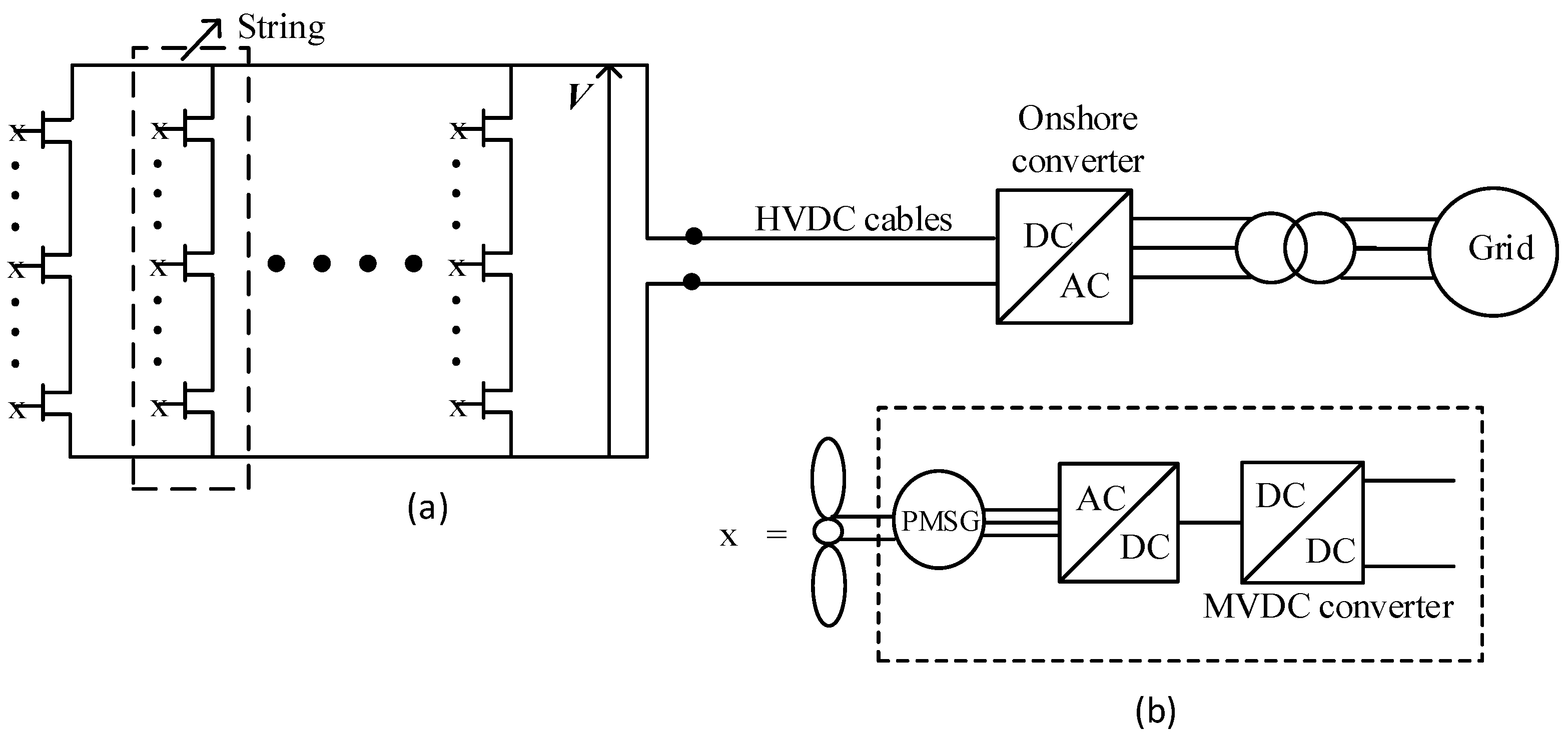
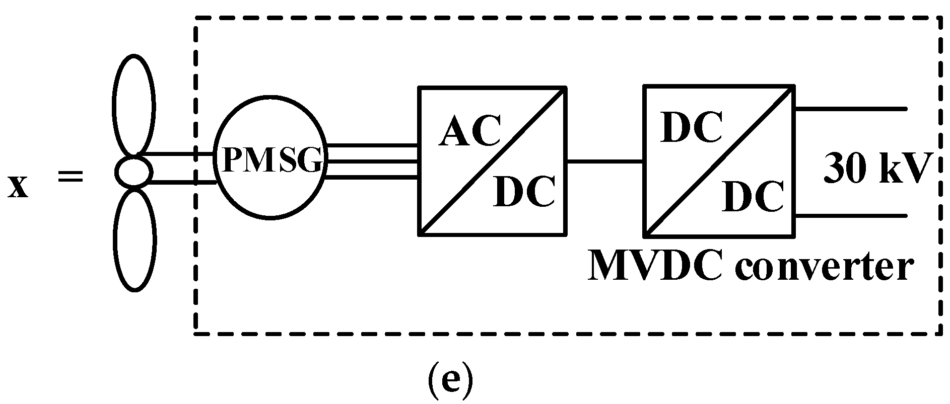
The configuration of the DC series–parallel connected wind farm is shown in Figure 1a. A PMSG (Permanent Magnet Synchronous Generator)-based wind power conversion system is considered. The output of the wind turbine converter is connected to an AC–DC converter and a medium-voltage DC (MVDC) converter as shown in Figure 1b. The MVDC converter steps up the DC output voltage wind turbine to the collection bus voltage.

Figure 1.
(a) DC series–parallel collection system. (b) Generators and power conversion components in an individual wind turbine.
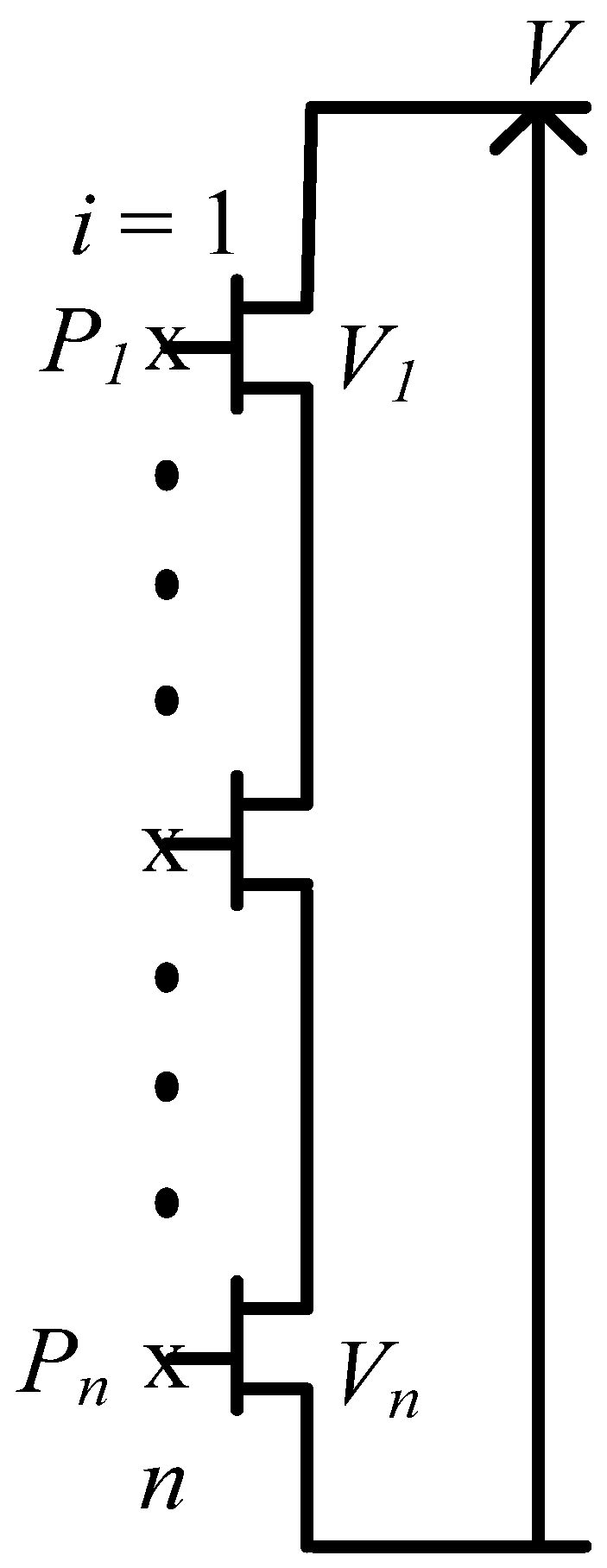
In a pure single DC series system, all the ‘n’ turbines are connected in the series (no. of strings ‘m’ = 1 for a single string; case similar to that shown in Figure 2). In DC series–parallel collection systems, the ‘m’ numbers of strings are connected in parallel. V refers to the string voltage, which is built by the individual DC output voltage of the ‘n’ number of the series-connected MVDC converters of the wind turbines. This string voltage V provides the required HVDC transmission voltage on the offshore side.

Figure 2.
Representation of one string of DC series–parallel offshore wind farms (it is assumed that ≥ ≥ ⋯ ≥ ).
Neglecting the voltage drop in the cables, the DC voltage is maintained as (see Figure 2)
n: Number of wind turbines in any single string.
: Nominal voltage of MVDC converter of the wind turbine.
: String voltage.
The output voltage of the th MVDC converter of the wind turbine in any single string is given by:
: Power output of the th turbine.
: Total string power.
In DC series–parallel collection systems, if the wind speed experienced by all the series-connected wind turbines in a string remains the same, the output voltages of the MVDC converters of wind turbines will be equal. In the case of wind speed inconsistencies between the series-connected turbines, the string voltage will be shared in proportion to the output power of the turbines, as shown in Equation (2). Here, it is assumed that the string voltage is kept constant by the grid side converter. The DC output voltage of the individual wind turbine is decided by the difference in the power output of the wind turbines.
The individual wind turbines in the series-connected string are expected to experience different wind speeds due to the different downwind distances adopted by the individual wind farms, the geometrical constraints, the wind speed variations caused by the wake effect, etc. As a result of this, the individual wind turbine DC output voltage is expected to vary widely depending on the wind speed differences between the individual wind turbines. The MVDC converters are designed to operate with a nominal output voltage with (typically ±5–±10%) some tolerance levels. When the output power of the individual turbines varies by a large amount, some of the MVDC converters will be subjected to an over-voltage condition. Some of the MVDC converters will reach their under-voltage tolerance levels. The relationship between the over- and under-voltage conditions, the number of series wind turbines connected in a string, and their power output differences are derived in [26]. To maintain the output voltage within the specified upper and lower tolerance levels, the output power of some wind turbines needs to be curtailed, which leads to energy curtailment losses.
The curtailment losses depend on the voltage tolerance levels of the MVDC converters. This paper compares and evaluates the power curtailment losses with fixed upper-voltage tolerance levels and redundancy-based upper-voltage tolerance levels for the MVDC converters of the wind turbines concerning the wind farm configurations of DC series–parallel-connected offshore wind farms. Based on the performed analysis, useful conclusions regarding wind farm configurations and curtailment losses have been identified.
2.1. Effect of Voltage Tolerance Levels of MVDC Converters on Energy Curtailment
In DC series–parallel collection systems, the power output differences between the series-connected turbines are due to the inconsistencies in the wind speed experienced by the wind turbines. The wind speed variations are mostly caused by wake effects [27,28,29]. Due to wake effects, wind leaving the turbine has a lower energy content than the wind upstream of the turbine, so the downstream wind turbines experience a reduced wind speed. The wake effect reduces the energy production of the wind farm. According to [28] a turbine spacing of 4–8 rotor diameters will cause a power loss of 5–15% of the total wind farm power output due to wake effects. The Horns rev offshore wind farm data measurement collected by [29] shows that the downwind turbines experience a reduction in the wind speed in the range of 15–20% compared to the upwind turbines.
The power output differences between the series-connected turbines decide the distribution of the output DC voltages in the MVDC converters of the wind turbine. A large difference in the power output will result in wide voltage variations in the output voltage of the wind turbine MVDC converters. To maintain the output voltage of the MVDC converters within the allowed tolerance, the useful output power of the wind turbines needs to be curtailed. The relationship between the output-voltage tolerance levels of the wind turbine MVDC converters and the different power outputs of the series-connected wind turbines are derived in [26] as
: Power output of the first wind turbine in a string (refer to Figure 2)
: Output-voltage tolerance level of wind turbine MVDC converter
Thus, if, the output voltages of all MVDC converters will be below the upper limit and no over-voltage occurs. This has been derived in [26] as a condition relating to the upper-voltage tolerance levels, the total string power, and the power output differences of the wind turbines.
The amount of power that needs to be curtailed is greater if the difference in the power output of the series-connected turbines is large, with fixed upper-voltage tolerance levels. This category is considered the fixed upper-voltage tolerance levels of wind turbine MVDC converters.
In DC series–parallel collection systems, the required string voltage is built by the series connection of the wind turbines in the string, which means that all the wind turbines must be available to build the required string voltage. This cannot be assured by providing fixed upper-voltage tolerance levels for the MVDC converters of the wind turbine in the event of losing the wind turbines. The upper-voltage tolerance levels can also be defined according to the redundancy requirements to avoid a loss of useful power caused by a condition called string failure, which is explained below.
2.2. Defining Upper-Voltage Tolerance Levels by Redundancy Requirements
To identify the required upper-voltage tolerance levels by the redundancy requirements, a condition called string failure is defined [30] in DC series–parallel collection systems. This refers to a condition, in which the series-connected wind turbines’ output DC voltages cannot build up the string voltage. The string failure condition might occur due to the wind turbine failures in the series-connected string or the inability of the wind turbine to produce output power due to some internal fault conditions or maintenance requirements. For DC series wind farms with a single string, the string failure would affect the entire wind farm and for DC series–parallel wind farms, the particular failed string needs to be bypassed [16] to continue the wind farm operation with the remaining parallel-connected strings. In addition to the power curtailments caused by the output power differences between the series-connected turbines, the string failure can also result in a loss of useful output power in DC series–parallel wind farms.
DC-based offshore wind farms with series–parallel power collection systems are still not a fully-developed technology and feasibility studies on analyzing the different operational and control challenges of DC series–parallel collection systems are being continuously studied in the literature. The focus of the paper is on quantifying the curtailment losses, which are considered to be one of the important operational challenges of DC series–parallel offshore wind farms. The possibility of bypassing faulty wind turbines is reported in the previous literature using bypassing diodes [16] and circuit breakers [24]. So, in keeping the main focus on estimating and quantifying the curtailment losses, a suitable assumption is made in which the wind farm can continue to be in operation by bypassing the faulty wind turbine. However, the practical realization of this aspect is not considered in detail in the present work as this analysis and expertise on bypassing faulty wind turbines would diverge from the main focus of the paper.
To avoid the loss of useful power caused by the string failure conditions, an ‘n − 1’ criterion of redundancy can be considered for each string. For this, the string voltage can be maintained even if any single wind turbine in the string is unavailable, i.e., the string voltage can still be maintained by an n − 1 wind turbine by providing suitable upper-voltage levels for the MVDC converters of the turbine. The failure of a single wind turbine of any string increases the DC output voltage of other wind turbines and compensates for the failed wind turbine in contributing to the string voltage.
The tolerance levels in the output voltages ( of wind turbine MVDC converters can be chosen using the ‘n − 1’ criterion of redundancy for the ‘n’ number of wind turbines in a string, the string voltage (), and the nominal output voltage of the wind turbine MVDC ( converter with set equal to one.
This means that if the number of wind turbines lost is more than nmax, this would cause a string failure condition.
Now, based on the above equation, the upper-voltage tolerance level for the wind turbine MVDC converters can be derived, considering an ‘n − 1’ criterion for the redundancy condition in each string. This means that wind turbine MVDC converters are sufficiently over-rated (with their decided by the number of series-connected turbines in a string), such that there is no possibility for a string failure with the failure of a single wind turbine in any string. This method will be termed as the specification of upper-voltage tolerance levels with respect to the ‘n − 1’ criterion for the redundancy requirement.
Providing a redundancy-based upper-voltage tolerance level for wind turbine MVDC converters is useful for reducing the loss of power caused by a string failure. This is also beneficial when considering the energy curtailment losses caused by the huge power difference among the series-connected turbines. The upper-voltage tolerance level in this category depends on the number of series-connected turbines and the string voltage of each string.
2.3. String Voltage Limits
In the discussions presented so far, the string voltage (which is the required HVDC transmission voltage) is assumed to be maintained at a constant by the onshore grid converter. However, allowing a small string voltage tolerance level was found to reduce the curtailment losses caused by power differences among the series-connected wind turbines. The authors of [26] explained that a 25% reduction in the string voltage tolerance levels helped to decrease the energy curtailment losses despite the small increase in the losses of the wind turbine MVDC converter and inter-array collection cables. However, variable string voltage tolerance levels can necessitate special control requirements in the case of DC series–parallel collection systems. This is because of the requirement for all parallel-connected strings to maintain the same string voltage in order to avoid the circulating currents.
3. Calculation of Power Curtailment Losses
The steps involved in the calculation of the energy curtailment losses are listed below.
- The windfarm layout for the DC series–parallel collection system is defined with respect to the number of wind turbines connected in the series, the number of strings connected in parallel, and the horizontal and vertical distances between the wind turbines.
- By using the well-known wake model developed by Jensen [31], the wind speed differences among the series-connected turbines are calculated considering both single and multiple wake effects. This has been carried out for the wind speeds ranging from the cut-in wind speed to the cut-out wind speed, taking into account the different wind direction sectors.
- The wind speed of each wind turbine in the string is calculated using step 2, and the output power of each wind turbine is calculated. The power outputs are assumed to be at the rated values beyond the rated speeds.
- The output power differences of the series-connected wind turbines decides the MVDC output voltage of the series-connected wind turbines in each case. Now, considering the ‘n − 1’ redundancy requirement in Equation (4), the upper-voltage tolerance levels for the wind turbine MVDC converter are identified. This factor varies concerning the configuration of the considered wind farms, depending on the number of wind turbines connected in the series.
- The quantity of the required power curtailment in order to maintain the identified upper-voltage tolerance levels of the wind turbine MVDC converter is calculated. This has been explained in [26] with respect to the different power curtailment modes. This has been carried out for all the strings in the wind farm for each combination of the wind speed and wind direction sectors. The total power curtailment losses of the wind farm are calculated as
: Total power curtailment losses of the wind farm.
: Wind speed.
: Sectors of wind direction.
: Number of strings.
: Total amount of power curtailment losses in each string.
is the total amount of power curtailed in each string to avoid over-voltage of wind turbine MVDC converters, which depends on the given output-voltage tolerance levels of the wind turbine MVDC converters.
- 6.
- The energy curtailment losses can be estimated using the total power curtailment losses of the wind farms calculated in the previous step.
: Total energy curtailment losses of the wind farm
: Duration of the period considered.
: Weibull probability function of the wind speed.
: Wind rose probability distribution of wind direction.
4. Case Study for Different Configurations of DC Series–Parallel Wind Farms
The case study considers a wind farm with DC series–parallel collection systems. The wind farm has 20 wind turbines each with a power output of 10 MW. The wind turbine parameters are shown in Table 1, which is based on the FINO 3 wind farm [32,33,34].

Table 1.
Wind turbine parameters [32,33,34].
This case study considered four different cases with several series-connected turbines and parallel-connected strings. The aim of this case study is to identify the impact of wind farm configurations on the number of power curtailments with the considered voltage tolerance levels of the MVDC converters. Depending on the number of series-connected turbines, the HVDC transmission output voltage varies. In an individual wind farm configuration, a constant HVDC voltage is expected to be maintained by the power electronic converters of the onshore grid.
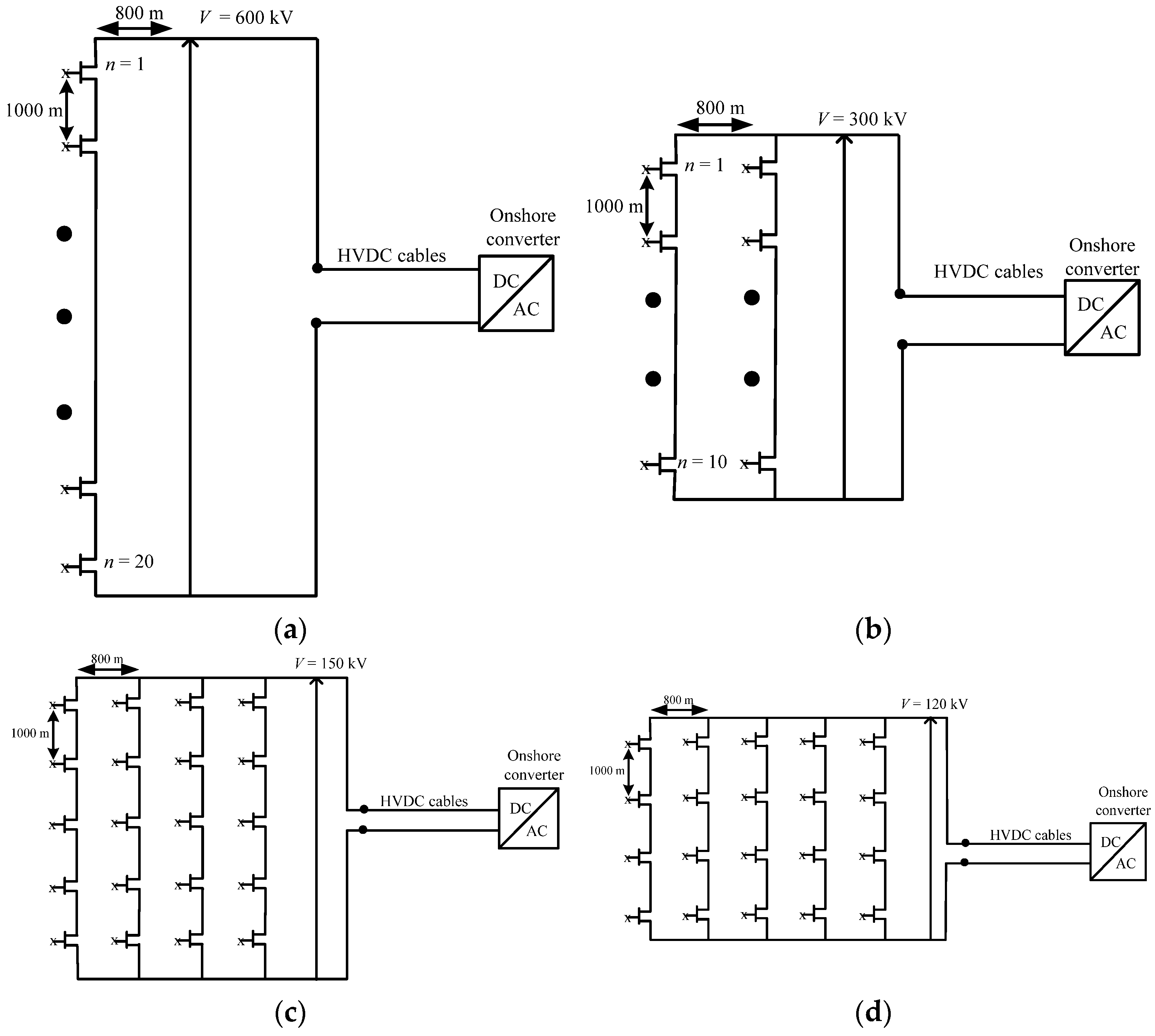
The wind turbine MVDC converter has a nominal output voltage of 30 kV and the string voltage is determined by the number of series-connected turbines in each case. The configurations of the wind farms used for the case study are shown in Figure 3. The first case of a wind farm configuration has all 20 wind turbines connected in a single string (20 × 1), as shown in Figure 3a. With the wind turbine MVDC converters having a nominal voltage of 30 kV, the string voltage adds up to 600 kV for the 20 series-connected turbines. This is called a pure single DC series wind farm. Case 2 (10 × 2) considers 2 strings with 10 turbines connected in a series in each string, as shown in Figure 3b. In this case, the string voltage adds up to 300 kV. Case 3 considers (5 × 4) four strings with five turbines connected in series in each string and a string voltage of 150 kV, as illustrated in Figure 3c. Case 4 (4 × 5) considers five strings with four turbines connected in a series in each string and a string voltage of 120 kV, as shown in Figure 3d.


Figure 3.
Configuration of the wind farms considered for the case study with DC series–parallel collection systems. (a) 20 × 1 turbines (pure DC series wind farm with a single string and 20 turbines connected in a series, HVDC voltage: 600 kV) (b) 10 × 2 turbines (DC series–parallel wind farm with 2 strings and each string with 10 series-connected turbines, HVDC voltage: 300 kV) (c) 5 × 4 turbines (DC series–parallel wind farm with 4 strings and each string with 5 series-connected turbines, HVDC voltage: 150 kV) (d) 4 × 5 turbines (DC series–parallel wind farm with 5 strings and each string with 4 series-connected turbines, HVDC voltage: 120 kV). (e) Generators and power conversion components in an individual wind turbine.
4.1. Upper-Voltage Tolerance Levels for Wind Turbine MVDC Converters
The upper-voltage tolerance levels of MVDC converters in the wind turbines are placed into two categories. One is to provide a fixed upper-voltage tolerance level of 10% in all four cases considered.
In the other category, the upper-voltage tolerance levels are defined according to ‘n − 1’ redundancy criterion from Equation (4) corresponding to Vn = 30 kV. For example, corresponding to case 1 with 20 × 1 turbines, n = 20, Vn = 30 kV, and V = 600 kV, according to Equation (4), the required for = 1 can be found as 5.3%.
Table 2 shows the upper-voltage tolerance levels of all four cases as decided by the redundancy requirements. Table 2 shows that for the case with a pure single DC series system, the redundancy-based upper-voltage tolerance level is smaller than the fixed upper-voltage tolerance level of 10%. Similarly, in case 2 with 10 wind turbines connected in a series, the redundancy-based upper-voltage tolerance level is closer to the fixed upper-voltage tolerance level. This means that with a greater number of series-connected wind turbines, the upper-voltage tolerance levels can be chosen either equal to or close to the fixed upper-voltage tolerance level, rather than choosing an ‘n − 1’ redundancy condition.
Table 2.
Upper-voltage tolerance levels are specified by redundancy.
It can also be seen that the required redundancy-based upper-voltage tolerance levels increase with the smaller numbers of series-connected turbines. This can be seen in the case with 5 turbines connected in a series, where the redundancy-based upper-voltage tolerance level is 25%, as well as in the case with 4 wind turbines connected in a series, where the upper-voltage tolerance level is 33.3%. The required upper-voltage tolerance levels are very high for the smaller numbers of series-connected turbines in cases 3 and 4 compared to those in cases 1 and 2.
4.2. Comparision of Energy Curtailment Losses with Fixed and Redundancy-Based Upper-Voltage Tolerance Levels
Using the steps in Section 4, an evaluation of the curtailment losses is carried out for the number of strings considered in the configuration of each wind farm considered in the case study. The wind speed probability distribution data uses the references from [32,33,34]. The Weibull parameters used are k = 2.25 and C = 11.2 m/s. The wind rose probability data of the FINO3 reference wind farm obtained from [34] are used for the evaluation of the power curtailment losses for the wind farm configurations considered in the case study.
The decay constant of the wake model used is 0.04. In wake models, the decay constant represents the effects of atmospheric stability and is set to 0.075 for onshore and 0.04 for offshore applications [27,28,29]. For the thrust coefficients, we use the reference data from [33]. The thrust coefficient in the wake model is associated with the thrust force and air density. It is a wind-turbine-specific constant and is usually manufacturer-specified. The wind speeds between the cut-in wind speed and the cut-out wind speed are considered. The number of incoming wind directions is considered to be 12 with 30° sectors of wind directions.
The case study has been conducted using MATLAB-based computations. MATLAB script files have been written to estimate the wind speed of the individual wind turbines following the prescribed wake models. Once the wind speed of the individual wind turbines in the string is estimated, the curtailment losses were evaluated using another set of MATLAB script files for all the wind speeds and wind direction sectors. Finally, the curtailment losses were estimated using the probability distribution function of the wind speeds and the wind directional sectors considered.
Table 3 compares the annual energy curtailment (AEC) losses using the fixed upper-voltage tolerance level of 10% and a redundancy-based upper-voltage tolerance level. With a fixed upper-voltage tolerance level of 10% for the wind turbine MVDC converter, the AEC losses are in the range of 0.28% to 1.95% for the DC series–parallel wind farm with a 200 MW capacity, depending on the number of series-connected turbines. For cases 1 and 2, the AEC losses were 0.28% and 0.51%, respectively.
Table 3.
Evaluation and comparison of AEC losses (using nominal string voltage).
The curtailment losses for cases 3 and 4 were 1.77% and 1.95%, respectively. Here, the power curtailment losses need to be calculated for the different sectors of wind direction. The curtailment losses increase with a greater number of parallel-connected strings because a greater number of upwind turbines in each string needs to undergo an output power curtailment to maintain the output-voltage tolerance levels.
Further, the energy curtailment losses were estimated for the redundancy-based upper-voltage tolerance level. The AEC losses corresponding to the upper-voltage tolerance levels specified in Table 2 are estimated.
For the wind farm configurations corresponding to case 1 (20 × 1), the upper-voltage tolerance level of the wind turbine MVDC converter is 5.3%, which is less than the considered fixed upper-voltage tolerance level of 10%. So, the curtailment losses for the wind farm in case 1 with the ‘n − 1’ redundancy condition is higher compared to the 10% fixed upper-voltage tolerance level.
For the wind farm configurations corresponding to case 2 (10 × 2), the upper-voltage tolerance levels of the wind turbine MVDC converters is 11%, which is closer to the considered fixed upper-voltage tolerance level of 10%. So, the curtailment losses for the case 2 wind farm with the ‘n − 1’ redundancy condition are nearly equal to the 10% upper-voltage tolerance level.
The energy curtailment losses were reduced from 1.77% to 1.1% in case 3 and 1.95% to 1.07% in case 4 using the redundancy-based upper-voltage tolerance level compared to the 10% fixed upper-voltage tolerance level.
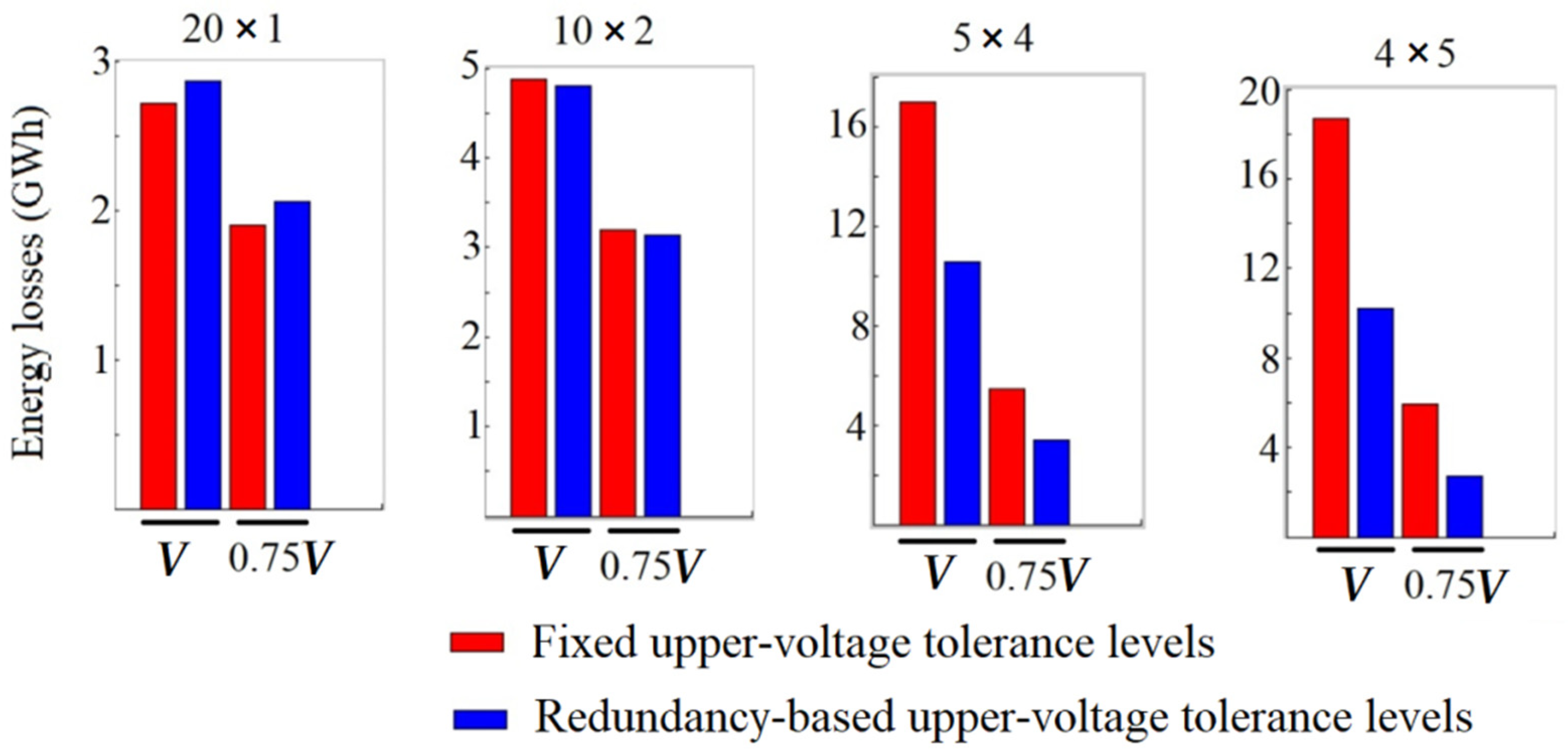
The results show that the redundancy-based upper-voltage tolerance level was not of much use in cases 1 and 2. If there is more flexibility to choose an upper-voltage tolerance level that is higher than the fixed upper-voltage tolerance level, the configurations in cases 3 and 4 could be preferred over cases 1 and case 2. Under such conditions, for cases 1 and 2, the redundancy can be increased from n − 1 to n − 2. This means that the nmax in Equation (4) can be chosen as 2. With this value of nmax, it is possible to build the string voltage using the wind turbine MVDC converters even with a failure of two turbines in any single string. So, this will increase the reliability of the configurations in cases 1 and 2. The AEC losses corresponding to the fixed upper-voltage tolerance levels and the redundancy-based upper-voltage tolerance levels are plotted in Figure 4.
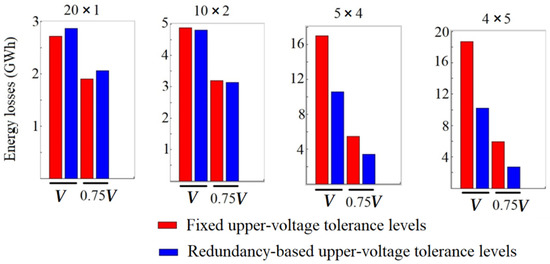
Figure 4.
Comparison of AEC losses with fixed and redundancy-based upper-voltage tolerance levels for different wind farm configurations.
The effects of varying the string voltage limits on the AEC losses are shown for both the fixed and redundancy-based upper-voltage tolerance levels in Table 4. Reducing the string voltage by 25% (this would require an appropriate over-current rating for the collections cables) can help to decrease the AEC losses. The authors in [26] have demonstrated that the reduction in the AEC losses was higher when compared to the increase in the losses of the collection cables and wind turbine MVDC converters. A similar trend to the results in Table 3 can also be observed in the results in Table 4.
Table 4.
Evaluation and comparison of AEC losses (using 25% reduction in string voltage).
This paper has carried out a comparative evaluation of fixed upper-voltage tolerance levels and redundancy-based upper-voltage tolerance levels for the MVDC converters of a DC series–parallel offshore wind farm. This study has discussed the following important observations regarding the wind farm configurations for DC series–parallel collection systems.
- DC-based wind farms with a greater number of series-connected turbines and a smaller number of parallel-connected strings (cases 1 and 2) can be designed with fixed upper-voltage tolerance levels. The curtailment losses were evaluated to be similar in the comparative study by considering fixed upper-voltage tolerance levels and redundancy-based upper-voltage tolerance levels for the MVDC converters of a DC series–parallel offshore wind farm. Hence, these configurations can be designed with fixed nominal upper-voltage tolerance levels, without oversizing the MVDC converters of the DC series–parallel wind farms.
- DC-based wind farm configurations with a greater number of parallel-connected strings and a smaller number of series-connected turbines (cases 3 and 4) can be designed with redundancy-based upper-voltage tolerance levels. The curtailment losses were evaluated to be lower with redundancy-based upper-voltage tolerance levels in the comparative study between fixed upper-voltage tolerance levels and redundancy-based upper-voltage tolerance levels for the MVDC converters of a DC series–parallel offshore wind farm. Hence, these configurations need to be designed with a redundancy-based upper-voltage tolerance level, which makes it essential to oversize the MVDC converters of the DC series–parallel wind farms.
This study illustrates the importance of choosing the required upper-voltage tolerance levels of wind turbine MVDC converters, taking into account the number of series-connected turbines in each case so as to minimize the curtailment losses and also avoid a loss of power caused by string failure conditions.
5. Conclusions
The power output differences between the series-connected wind turbines and the output-voltage tolerance levels of wind turbine MVDC converters are critical parameters in DC series collection systems as they decide the amount of power to be curtailed in order to maintain the wind turbine MVDC converters’ voltages within the allowable tolerance levels. The AEC losses are analyzed and quantified for a 200 MW DC series–parallel wind farm with fixed upper-voltage and redundancy-based upper-voltage tolerance levels of the wind turbine MVDC converters by considering different wind farm configurations. The curtailment losses are found to be reduced using the redundancy-based upper-voltage tolerance levels for DC series–parallel wind farms compared to the pure, single DC series wind farms. Novel DC-based wind farm power collection systems can be considered alternative feasible topologies for achieving a reduced footprint and size for offshore wind farms by eliminating redundant power conversion stages and offshore platforms. Hence, it is necessary to perform a curtailment analysis study similar to the one reported in this paper to understand the operational challenges of DC-based wind farms and provide possible solutions by analyzing different wind farm configurations. These initial results are useful for performing further research on identifying optimal wind farm configurations for DC series–parallel power collection systems.
Funding
This research received no external funding.
Institutional Review Board Statement
Not applicable.
Informed Consent Statement
Not applicable.
Conflicts of Interest
The authors declare no conflict of interest.
References
- Bahirat, H.J.; Mork, B.A.; Hoidalen, H.K. Comparison of wind farm topologies for offshore applications. In Proceedings of the 2012 IEEE Power and Energy Society General Meeting, San Diego, CA, USA, 22–26 July 2012; pp. 1–8. [Google Scholar] [CrossRef]
- Bresesti, P.; Kling, W.; Hendriks, R.; Vailati, R. HVDC connection of offshore wind farms to the transmission system. IEEE Trans. Energy Convers. 2007, 22, 37–43. [Google Scholar] [CrossRef]
- Rahman, S.; Khan, I.; Alkhammash, H.; Nadeem, M. A Comparison Review on Transmission Mode for Onshore Integration of Offshore Wind Farms: HVDC or HVAC. Electronics 2021, 10, 1489. [Google Scholar] [CrossRef]
- Jiang, R.; Wang, J.; Guan, Y. Overview of Multi-MW Wind Turbines and Wind Parks. IEEE Trans. Ind. Electron. 2011, 58, 1081–1095. [Google Scholar] [CrossRef]
- Chen, Z.; Guerrero, J.M.; Blaabjerg, F. A review of the state of the art of power electronics for wind turbines. IEEE Trans. Power Electron. 2009, 24, 1859–1875. [Google Scholar] [CrossRef]
- Gomis-Bellmunt, O.; Junyent-Ferré, A.; Sumper, A.; Bergas-Jané, J. Control of a wind farm based on synchronous generators with a central HVDC-VSC converter. IEEE Trans. Power Syst. 2011, 26, 1632–1640. [Google Scholar] [CrossRef] [Green Version]
- Jovcic, D. Offshore wind farm with a series multiterminal CSI HVDC. Electr. Power Syst. Res. 2008, 78, 747–755. [Google Scholar] [CrossRef]
- Robinson, J.; Jovcic, D.; Joos, G. Analysis and design of an offshore wind farm using a MV DC Grid. IEEE Trans. Power Deliv. 2010, 25, 2164–2173. [Google Scholar] [CrossRef]
- Meyer, C. Key Components for Future Offshore Dc Grids. Ph.D. Thesis, Rheinisch-Westfallischen Technischen Hochschule Aachen, Aachen, Germany, 2007. [Google Scholar]
- Jovcic, D.; Strachan, N. Offshore wind farm with centralized power conversion and DC interconnection. IET Gener. Transm. Distrib. 2009, 3, 586–595. [Google Scholar] [CrossRef]
- Meyer, C.; Hoing, M.; Peterson, A.; De Doncker, R.W. Control and design of DC grids for offshore wind farms. IEEE Trans. Ind. Appl. 2007, 43, 1475–1482. [Google Scholar] [CrossRef]
- Lakshmanan, P.; Liang, J.; Jenkins, N. Assessment of collection systems for HVDC connected offshore wind farms. Electr. Power Syst. Res. 2015, 129, 75–82. [Google Scholar] [CrossRef] [Green Version]
- Holtsmark, N.; Bahirat, H.J.; Molinas, M.; Mork, B.A.; Hoidalen, H.K. An All-DC offshore wind farm with series-connected turbines: An alternative to the classical parallel AC model? IEEE Trans. Ind. Electron. 2013, 60, 2420–2428. [Google Scholar] [CrossRef]
- Veilleux, E.; Lehn, P.W. Interconnection of Direct-Drive Wind Turbines Using a Series-Connected DC Grid. IEEE Trans. Sustain. Energy 2013, 5, 139–147. [Google Scholar] [CrossRef] [Green Version]
- Bahirat, H.J.; Kjolle, G.H.; Mork, B.A.; Hoidalen, H.K. Reliability assessment of DC wind farms. In Proceedings of the IEEE Power and Energy Society General Meeting, San Diego, CA, USA, 22–26 July 2012; pp. 1–7. [Google Scholar]
- Tatsuta, F.; Nishikata, S. Dynamic performance analysis of a wind turbine generating system with series connected wind generators and bypass diodes using a current source thyristor inverter. In Proceedings of the 2010 International Power Electronics Conference (TPEC2010), Sapporo, Japan, 21–24 June 2010; pp. 1830–1836. [Google Scholar] [CrossRef]
- Nishikata, S.; Tatsuta, F. A New Interconnecting Method for Wind Turbine/Generators in a Wind Farm. IEEE Trans. Ind. Electron. 2010, 57, 468–475. [Google Scholar] [CrossRef]
- Popat, M.; Wu, B.; Liu, F.; Zargari, N. Coordinated Control of Cascaded Current-Source Converter Based Offshore Wind Farm. IEEE Trans. Sustain. Energy 2012, 3, 557–565. [Google Scholar] [CrossRef]
- Garcés, A.; Molinas, M. Coordinated control of series-connected offshore wind park based on matrix converters. Wind Energy 2012, 15, 827–845. [Google Scholar] [CrossRef]
- Rong, F.; Wu, G.; Li, X.; Huang, S.; Zhou, B. ALL-DC Offshore Wind Farm With Series-Connected Wind Turbines to Over-come Unequal Wind Speeds. IEEE Trans. Power Electron. 2019, 34, 1370–1381. [Google Scholar] [CrossRef]
- Bahirat, H.J.; Mork, B.A. Operation of DC Series–Parallel Connected Offshore Wind Farm. IEEE Trans. Sustain. Energy 2018, 10, 596–603. [Google Scholar] [CrossRef]
- Zhang, H.; Gruson, F.; Rodriguez, D.M.F.; Saudemont, C. Overvoltage Limitation Method of an Offshore Wind Farm with DC Series-Parallel Collection Grid. IEEE Trans. Sustain. Energy 2018, 10, 204–213. [Google Scholar] [CrossRef] [Green Version]
- Lundberg, S. Wind Farm Configuration and Energy Efficiency Studies—Series DC versus AC Layouts. Ph.D. Thesis, Chalmers University of Technology, Goteborg, Sweden, 2006. [Google Scholar]
- Chuangpishit, S.; Tabesh, A.; Moradi-Sharbabk, Z.; Saeedifard, M. Topology Design for Collector Systems of Offshore Wind Farms with Pure DC Power Systems. IEEE Trans. Ind. Electron. 2013, 61, 320–328. [Google Scholar] [CrossRef]
- Pape, M.; Kazerani, M. A Generic Power Converter Sizing Framework for Series-Connected DC Offshore Wind Farms. IEEE Trans. Power Electron. 2021, 37, 2307–2320. [Google Scholar] [CrossRef]
- Lakshmanan, P.; Guo, J.; Liang, J. Energy curtailment of DC series–parallel connected offshore wind farms. IET Renew. Power Gener. 2018, 12, 576–584. [Google Scholar] [CrossRef]
- Frandsen, S.; Barthelmie, R.; Pryor, S.; Rathmann, O.; Larsen, S.; Højstrup, J.; Thøgersen, M. Analytical modelling of wind speed deficit in large offshore wind farms. Wind Energy 2006, 9, 39–53. [Google Scholar] [CrossRef]
- Barthelmie, R.J.; Larsen, G.C.; Frandsen, S.T.; Folkerts, L.; Rados, K.; Pryor, S.C.; Lange, B.; Schepers, G. Comparison of Wake Model Simulations with Offshore Wind Turbine Wake Profiles Measured by Sodar. J. Atmos. Ocean. Technol. 2006, 23, 888–901. [Google Scholar] [CrossRef]
- Barthelmie, R.; Frandsen, S.T.; Rathmann, O.; Hansen, K.; Politis, E.S.; Prospathopoulos, J.; Schepers, J.G.; Rados, K.; Cabezón, D.; Schlez, W.; et al. Flow and Wakes in Large Wind Farms: Final Report for Upwind WP8, February 2011. Available online: https://www.osti.gov/etdeweb/servlets/purl/1016226 (accessed on 10 May 2022).
- Guo, J.; Wang, X.; Zhang, Z.; Li, H.; Lakshmanan, P.; Liang, J. Energy curtailment analysis of offshore wind farms with DC series-parallel collection systems. In Proceedings of the DRPT-2015, Changsha, China, 26–29 November 2015. [Google Scholar] [CrossRef]
- Jensen, N.O. A Note on Wind Generator Interaction; Technical Report; Risø National Laboratory: Roskilde, Denmark; p. RISØ-M-24111983.
- Hou, P.; Hu, W.; Soltani, M.; Chen, Z. Optimized Placement of Wind Turbines in Large-Scale Offshore Wind Farm Using Particle Swarm Optimization Algorithm. IEEE Trans. Sustain. Energy 2015, 6, 1272–1282. [Google Scholar] [CrossRef] [Green Version]
- Bak, C.; Zahle, F.; Bitsche, R.; Kim, T.; Yde, A.; Henriksen, L.C.; Hansen, M.H.; Blasques, J.P.A.A.; Gaunaa, M.; Natarajan, A.; et al. Description of the DTU 10 MW Reference Wind Turbine; DTU Wind Energy: Fredericia, Denmark, 2013. [Google Scholar]
- R&D centre Kiel University of Applied Sciences GmbH, FINO3—Research Platform in the North Sea and the Baltic No. 3 [Online]. Available online: http://www.fino3.de/en/ (accessed on 10 May 2022).
Publisher’s Note: MDPI stays neutral with regard to jurisdictional claims in published maps and institutional affiliations. |
© 2022 by the author. Licensee MDPI, Basel, Switzerland. This article is an open access article distributed under the terms and conditions of the Creative Commons Attribution (CC BY) license (https://creativecommons.org/licenses/by/4.0/).