1. Introduction
With the aim of reducing costs and energy consumption, the demands on materials used in lightweight structures are increasing. For example, in aircraft construction applications, aluminum alloys are increasingly more used to their limits. In addition, it is necessary to make accurate predictions by means of simulations about the service life as well as the material behavior, including plasticity, damage, and failure. In the case of sheet materials, it should also be noted that plastic anisotropies are relevant and have to be taken into account in the material description. Furthermore, ductile damage of these materials is stress-state-dependent, and micro-defects can cause failure on the macro scale. Therefore, the interaction of theoretical material description, numerical implementation, and experiments for material investigation and validation are of central importance. This publication emphasizes the experimental investigation of the material behavior. The focus is on plastic anisotropy, stress-state-dependent damage behavior, biaxial experiments, and specimen design.
Un-notched uniaxially loaded tension specimens are commonly used to identify the elastic–plastic material parameters because they are characterized by a homogeneous stress and strain state before necking takes place. In this context, the stress triaxiality, defined as the ratio of the mean stress and the von Mises equivalent stress, is seen as a relevant quantity to characterize the stress state. With differently notched tension specimens, a first approach can be made as increasing tension-dominated stress triaxialities can be achieved with decreasing notch radius [
1,
2]. Shear-dominated stress states with stress triaxialities around zero can be geometrically enforced with uniaxially loaded, specially designed specimens (see, for instance, [
3,
4,
5]). The aforementioned geometries can be used for one loading condition, leading to a characteristic stress state that generally changes slightly with ongoing deformation. For more arbitrary non-proportional loading, it is crucial that one specimen can be used under different loading conditions. This idea has been presented in [
6] for the Arcan specimen where different loading angles cause in the region of interest different stress states and has been continued by [
7] in the design of the butterfly specimen. Moreover, classical cruciform geometries have been proposed to analyze the yield surface and the subsequent plastic behavior (see [
8] for a detailed discussion). These classical cruciform specimens follow the idea of homogeneously distributed stress and strain states, but ongoing deformation strains tend to localize, and a well-controlled study of damage and fracture under pre-defined loading conditions is difficult to realize. See [
9] for a detailed discussion of specimen geometries, corresponding stress state, and ductile damage.
During the last years, several new biaxially loaded test specimens, specifically de- signed to investigate and quantify the damage behavior, have been presented by Gerke et al. [
10]. The design of the new geometries was based on the following observations:
If a wide range of stress conditions has to be investigated, a geometry that allows this is particularly user-friendly. This also makes non-proportional load paths possible.
Damage processes have the tendency to localize, and therefore areas of reduced cross-section can be used to specify the area of greater deformation, final failure, and to control the stress states in these areas.
Digital image correlation (DIC) has been established for measuring deformations on test specimen surfaces. For its effective use, the region of interest must be kept compact [
9,
11].
In this paper, in addition to the damage, the focus is on the anisotropic-plastic material behavior. For this purpose, the H-specimen, the material, and the experimental methods are presented first. Subsequently, two load cases in the shear and in the shear compression range are discussed in detail.
2. Methods and Material
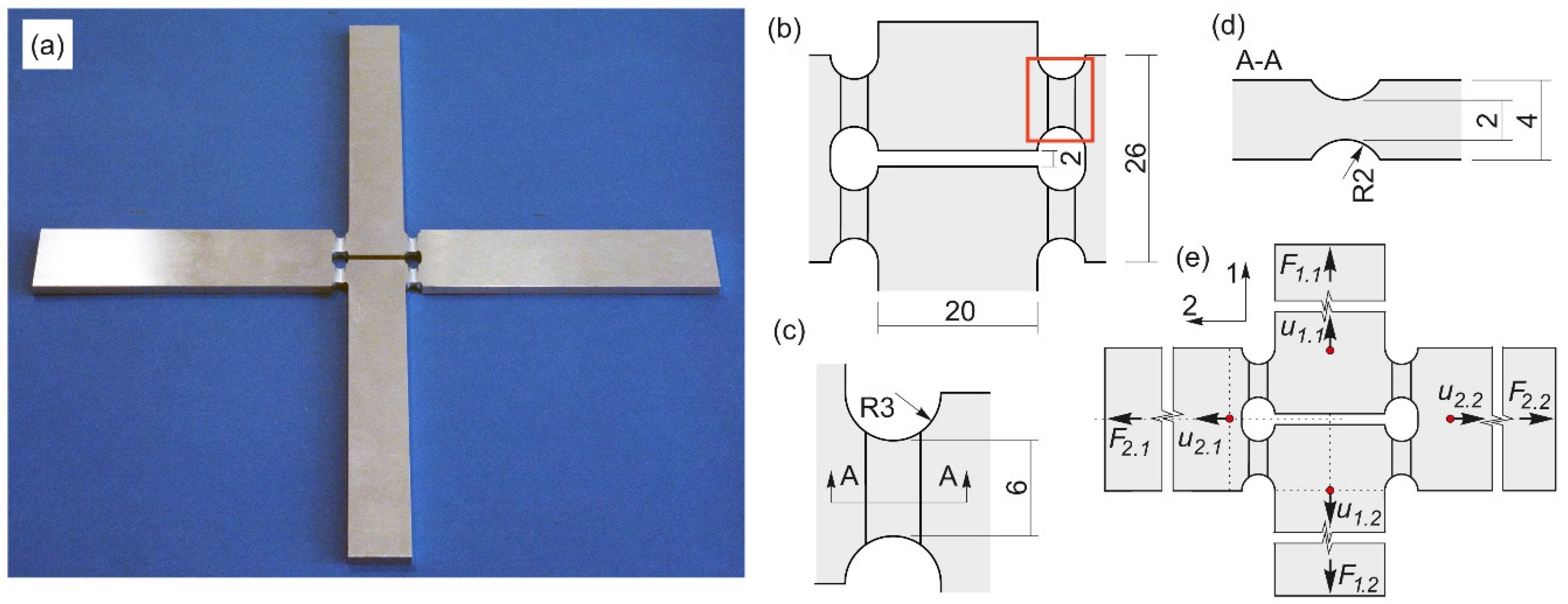
The geometry of the H-specimen is displayed in
Figure 1a and has outer dimensions of 240 × 240 mm; the notches are arranged parallel to axis 1, and consequently, it is possible to estimate the loading conditions in this area. Details of the dimensions of the central region can be seen in
Figure 1b–d. In addition, it can be mentioned that in
Section 3, the results are presented for the red marked region
Figure 1b.
All experiments were performed with the biaxial test machine LFM-BIAX 20 kN produced by Walter+Bai, Löhningen, Switzerland. It contains four electromechanically driven cylinders, and the specimens were clamped in the four heads (see
Figure 2a). The machine displacements
as well as the applied forces
of each cylinder (see
Figure 1e) were transferred to the digital image correlation (DIC) system provided by Dantec/Limess, Krefeld, Germany and stored with the DIC datasets. To avoid buckling, a pneumatic down-holder was introduced for load cases with applied compression forces (
Figure 2b,c). A low friction coefficient between specimen and down-holder was achieved with a pressure of 1 bar in the down-holder system and an applied lubricant to the contact surfaces. To extract the displacements and strain fields, a Dantec/Limess DIC system in stereo setup with two 6MPx cameras equipped with 75 mm lenses, as shown in
Figure 2a, was used. The system achieved a spatial resolution of 80 Px/mm and a subset size of 33 Px, with grid spacing of 11 Px being used for the evaluation in the corresponding Istra4D software.
Non-symmetric behavior during the experiments was avoided mainly by the displacement driven procedure [
10,
11], which can be outlined on the basis of the notation introduced in
Figure 1e as follows:
The leading machine displacement of cylinder 1.1 was continuously increased;
The same displacement was applied on the cylinder 1.2 on the opposite side;
The generated force was taken, multiplied by the load factor, and applied on the cylinder 2.1, resulting in the machine displacement ;
The same machine displacement was applied as on the opposite side.
This experimental routine is very stable, but it has to be pointed out that the relation between the machine and the nominal displacements is non-linear and depends on the load case.
The sheet material under investigation was the aluminum–copper (AlCu) alloy EN AW2017A with a thickness of 4 mm, being mainly used in aircraft applications. The chemical composition is shown in
Table 1. All specimens tested here were milled with high precision.
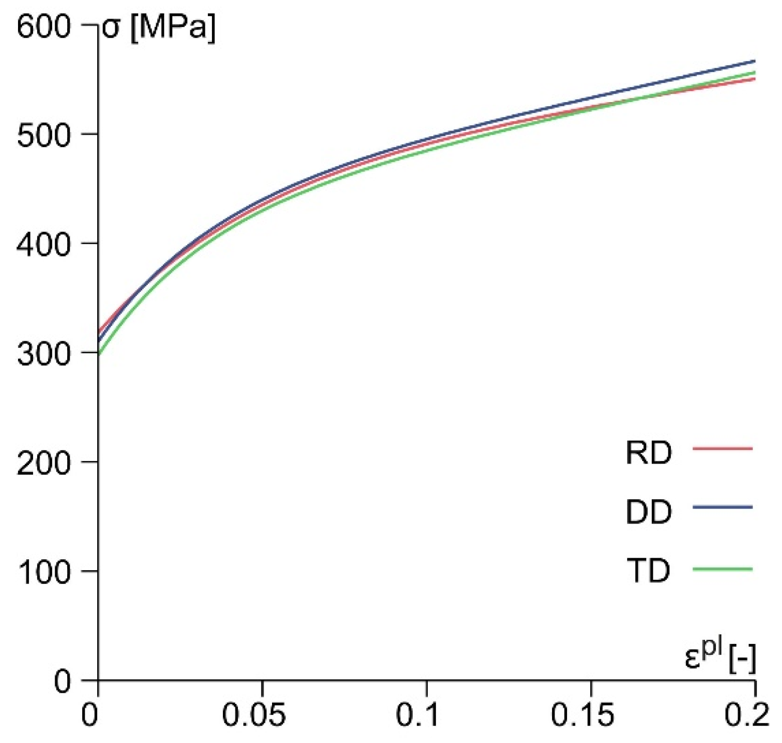
Figure 3 displays representative true stress–true plastic strain curves obtained with tension specimens cut in rolling direction (RD), diagonal direction (DD), and transverse direction (TD).
Assuming plane stress conditions
and taking into account the stress–strain curves (
Figure 3), the material parameter identification was realized. The Hill yield condition [
12] is given by
where
F,
G,
H, and
N are material parameters and
represents the equivalent yield stress of the chosen reference test in rolling direction (RD) (see
Figure 3). The plastic hardening is adequately described by the Voce law [
13]
with the hardening modulus
and
and the hardening exponent
n.
On the basis of the determined Lankford coefficients [
14] (
,
, and
) and the extracted true stress–true strain curves, the complete set of material parameters for the corresponding three-dimensional numerical simulations including the parameters L and M of the three-dimensional Hill yield condition is given in
Table 2 (see [
15] for detailed description).
3. Results and Discussion
In this paper, two load cases with the H-specimen leading to different stress states in the notched regions are presented. As adequate nominal displacement measures, the differences
and the forces
were chosen. Under
, shear-like loading conditions are enforced in the notches, whereas under
, shear loading is superimposed with compression. This newly applied shear-compression loading can only be realized with the previously described down-holder and can be seen as an important completion to the load cases presented in [
14].
Figure 4 shows the experimental load–displacement curves of both load cases. The experiments with load ratio
indicate on axis 1 displacements between
(TD) and
(DD) and forces from
F1 = 7.3 kN (DD) to 7.5 kN (RD). On axis 2, zero forces were retained by small negative displacements. Under
, loading on axis 1 displacements of
were reached for all material directions and forces from
F1 = 6.3 kN (DD) to 6.5 kN (RD). On axis 2, displacements between
(RD) and
(DD) and forces from
F2 = −12.6 kN (DD) to −13.3 kN (RD) were obtained. Thus, the specified load ratio was well maintained during the test and the influence of material direction was particularly notable. The largest difference indicates the experiment with loading
in RD on axis 2.
Numerical simulations with the anisotropic material model presented in
Section 2 provide valuable information regarding the stress triaxiality in the notched region of the specimen. For
loading, the stress triaxiality was very homogeneously distributed in the cross-section of the notch with values of approximately 0.1 (
Figure 5a). The influence of the material direction was small but visible; for instance, the experiment in rolling direction,
Figure 5a (RD), indicates marginally higher values. The numerical simulations with loading ratio
indicate negative stress triaxialities with values between −0.48 and −0.30. Due to the superimposed compression, the effect of the notched geometry led to unavoidable gradients in the distribution.
The strain fields in the notched region were monitored by digital image correlation (DIC), and the von Mises equivalent strain was chosen as a scalar value to display the corresponding strain fields. Enforced mainly by the displacement-driven machine control, the geometry behaved very symmetrically during the experiments, and only shortly before fracture occurrence could non-symmetric behavior be observed [
14].
Figure 6 indicates the strain distribution of the marked notch (
Figure 1b) at 70% of the displacement
at fracture. For shear loading
, a slightly inclined band with higher strains and values up to 0.26 was observed for all material directions (see
Figure 6a). For superimposed compression, the inclination of the band increased, whereas maximum strains decreased to values of 0.21 (
Figure 6b). Furthermore, the band under
had a minor width compared to
loading, leading to smaller displacements
at fracture (see
Figure 4).
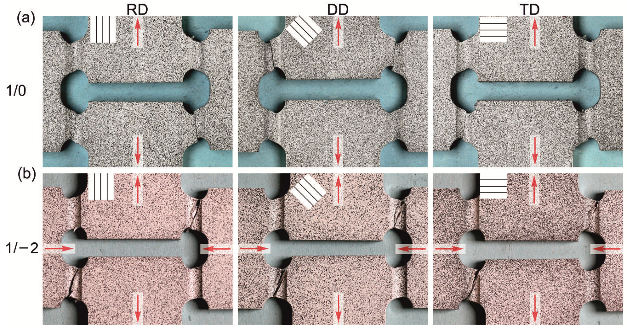
In
Figure 7, photos of the fractured specimens are shown for the two load cases and different material orientations. The directions of the fracture lines corresponded to the observed zones in
Figure 6 with elevated strain bands and the non-fractured notches indicate, in comparison to the fractured notches, similar inelastic deformations. Furthermore, the fracture patterns did not follow a strict regularity, and frequently two diagonally arranged notches fractured, but also cases with two failed notches on one side appeared. In particular, for the load ratio
(
Figure 7a), the fracture line was only slightly inclined, which refers to a shear-dominated fracture mode. In the case of superimposed compression (
,
Figure 7b), the fracture line was slightly curved but smooth, indicating the influence of the load case. For both load cases, the effect of the material orientation was marginal.
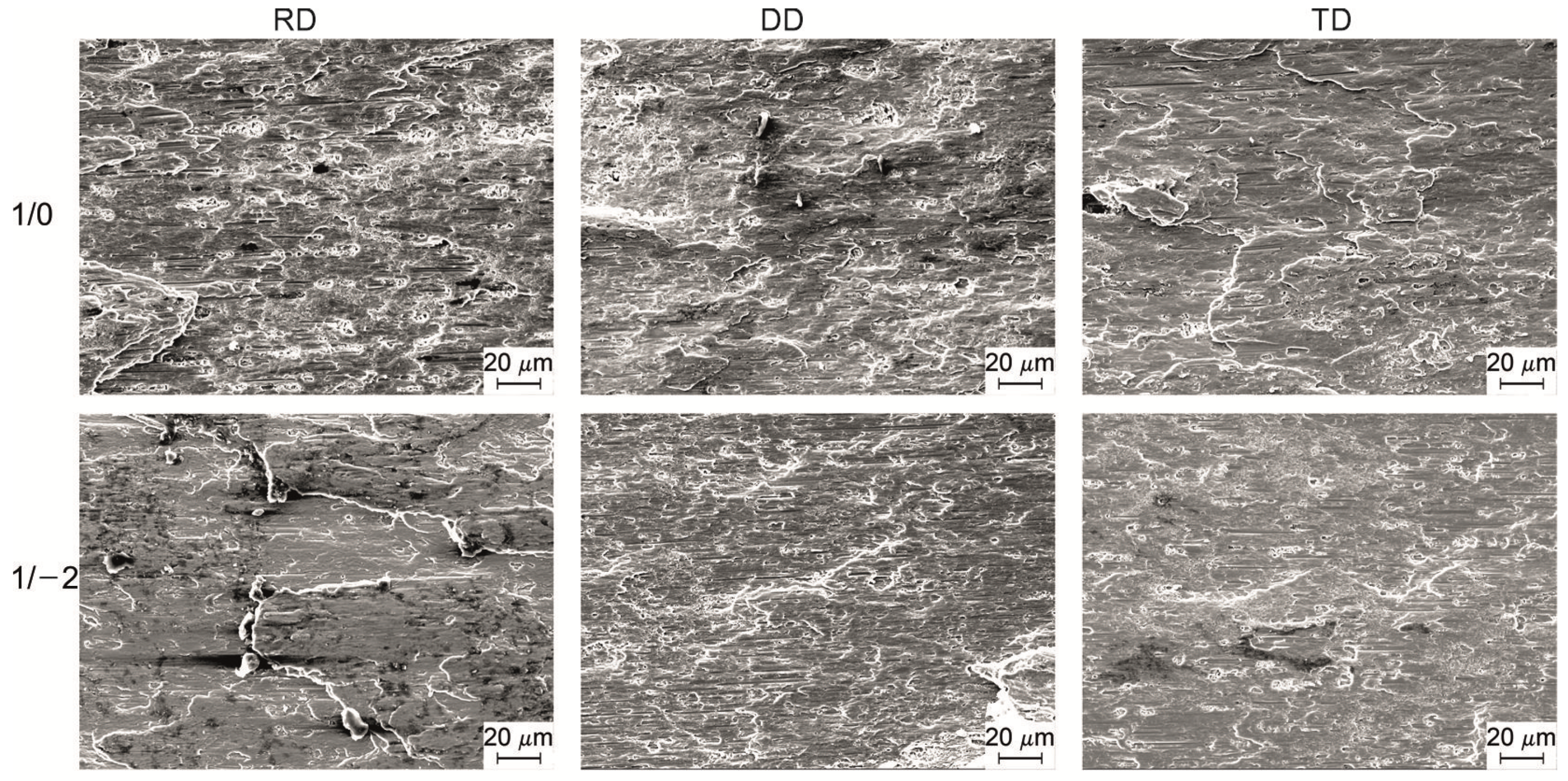
Generally, the evaluation of the fracture surfaces after the experiment by scanning electron microscopy (SEM) reveals the damage processes prior to fracture (see, for instance, [
14,
15]), including shear and shear-tension load cases.
Figure 8 shows the respective pictures taken at the center of the fracture surfaces for shear loading (a) and shear-compression loading (b), as well as different material orientations. All surfaces indicated shear fracture initiated by micro-shear cracks, with minor differences being identifiable. Under shear loading (
) with stress triaxialities around 0.1, small voids were visible for material orientations RD and DD (
Figure 8, top row), which cannot be noted under superimposed compression (
,
Figure 8, lower row). It has to be mentioned that especially for the herein investigated shear-compression load case (
,
Figure 8, lower row), contact of the fracture surface after failure cannot be excluded, which would affect the observations significantly.


