Abstract
The post-impact residual behaviour of a modified-matrix glass fiber laminated composite is analysed. The matrix of the laminate was modified by mixing it with 1/4” long chopped glass fibers in up to 4% volume fractions. Beam impact tests were performed at 7.5 J and 12.5 J impact energies with fixed boundary conditions. The data suggest that the impact resistance as well as the elastic response of the laminates increase with increasing chopped fiber content. Flexural test results showed improved residual properties in the case of reinforced epoxy laminates. Microscopic damage analysis shows a good correlation with laminates’ impact performance parameters.
1. Introduction
Glass fiber laminates have become key components of aerospace and high-performance automotive structures due to their high specific strength and stiffness. Besides being cost effective, they are also corrosion resistant and show good dielectric properties, although their lower out-of-plane properties have always been a cause for concern. While the laminates, in general, are susceptible to impact damage, low-velocity impacts need special attention because failure often remains obscured in between the laminae, which significantly deteriorates the load-carrying capacity of the laminates. Various techniques have been adopted in the past to enhance the impact characteristics of laminates by strengthening their matrices using nanofillers [1,2], rubber and plastic particles [3,4], or by stitching [5] and Z-pinning [6,7] the laminates. Among the adopted methods, modifying the laminate matrix by employing chopped fibers is not very common due to processing complexities.
Hu et al. [8] reinforced a unidirectional carbon prepreg–epoxy laminate with 3 mm chopped kevlar fibers at 10 g/m2 equivalent weight in the epoxy system. They conducted an impact test with 0.85 J/ply loadings. They reported a lower maximum contact force and dent depth for the chopped fiber-reinforced epoxy laminate as compared to an unreinforced one. In some cases, they observed reduced absorbed energy for the reinforced laminate. They reported that the damaged area increased with increasing impact energy, but the reinforcement had no effect on it. They also observed higher compression-after-impact strength for the reinforced laminate at all impact loadings. Yuan et al. [9] used a weaved carbon fabric–epoxy laminate of 11 plies and reinforced its interlaminar region with 4 grams per square meter (GSM) and 8 GSM non-woven veils with aramid fibers 3 to 4 mm in length and 12 μm in diameter. The laminated plates were impacted at energy levels of up to 5.7 J. They prepared 90 mm × 15 mm beam samples from the impacted plates and performed three-point bend flexural tests. The flexural modulus and flexural strength of the 4 GSM impacted samples increased when compared with the pristine beam case, but the 8 GSM laminate exhibited enhancement in flexural modulus with a detrimental effect on flexural strength. The authors reported that the free ends of the short fibers were pushed into the adjacent carbon fiber laminae, thus developing bridging between the plies in the case of the 4 GSM interleaved laminate.
To evaluate the post-impact health of a laminate, often, the compression-after-impact (CAI) test method is used [4]. The method requires a large robust setup with a precise data acquisition system. Santiuste et al. [10] conducted impact tests on beam samples of plane woven glass fiber–polyester laminated composites with dimensions of 20 mm × 120 mm and 50 mm × 120 mm. They assessed the post-impact characteristics of the laminate by employing three-point bend flexural tests. They outlined that the energy absorbed by the specimen in the dissipation mechanism increases with increase in incident energy, whereas the flexural strength decreases. They observed matrix failure and fiber fracture beyond critical incident energy. Balakrishnan et al. [11] studied low-velocity impact and post-impact flexural response for a unidirectional glass fiber polyamide-6 (thermoplastic) laminated composite with a [02,902]s stacking configuration. They prepared laminates at four different processing pressures and curing temperatures: 1.11 bar and 245 °C, 2.77 bar and 245 °C, 2.77 bar and 235 °C, 2.77 bar and 255 °C. They subjected the laminated plates (with dimensions of 150 mm× 100 mm) to 35 J impact energy. They reported three damage mechanisms: debonding between 0° and 90° layers; delamination propagation within 90° layers; and fiber breakage in the lower layer, which propagated towards the top layer. They conducted three-point bend flexural tests on the impacted samples, prepared as beams with 90 mm spans, and reported that the samples prepared at 2.77 bar and 235 °C temperature exhibited the highest flexural properties in their pristine state and the lowest flexural after-impact characteristics. The reversing trend was noted in the case of the sample prepared at 1.11 bar and 245 °C, pressure and temperature, respectively. Hart et al. [12] used two-dimensional and three-dimensional glass fiber composites of equivalent areal density to analysed post impact properties using compression-after-impact (CAI) and flexural after-impact (FAI) testing methods. They conducted impact tests on beam (110 mm × 20 mm dimension) and plate (101 mm × 101 mm dimension) samples with loadings between 25 J and 100 J, respectively. They reported lower post impact residual flexural strength in both 2D and 3D laminates. Whereas a reduction in post impact normalised compressive strength was only noticed in the 2D laminate samples.
The literature review suggests that among different methods used to enhance the impact resistance of laminated composites, matrix modification via chopped fiber reinforcement is not very common. Furthermore, in spite of the complexities involved, the CAI protocol is often employed to estimate the post-impact attributes of laminates due to the absence of any alternative. In this study, the effect of chopped fiber reinforcement on the impact response and post-impact residual properties of laminated composites was analysed by employing a new, simple and cost-effective FAI protocol.
2. Laminate Fabrication and Experimental Techniques
2.1. Material Processing
Sixteen-ply bi-directional plain-weave glass fabric laminates were fabricated using an epoxy matrix reinforced with chopped glass fibers 1/4” long and 16 µm in diameter. A requisite amount of chopped fibers was added into the Diglycidyl Ether of Bisphenol-A (DGEBA) resin. The fillers were uniformly dispersed into the resin by mechanical stirring and sonication. Methyl Tetra Hydrophthalic Anhydride (MTHPA) hardener was then mixed in a 1:1 resin–hardener ratio with a small quantity of 2,4,5-tris[(dimethylamino)methyl]-Phenol accelerator. The developed matrix system was used to prepare the laminates by the hand lay-up technique, after which they were cured in a vacuum-assisted hot press. In this study, three different matrix systems were used: unfilled epoxy, the 2% chopped fiber-reinforced epoxy and 4% reinforced epoxy. The associated laminates are referred to as ‘UR’ (unreinforced), ‘2% R’ and ‘4% R’, respectively, in the following sections.
2.2. Low-Velocity Impact Test
Beam specimens with dimensions of 110 mm × 16 mm × 4.5 mm were machined from the cured laminates and tested under low-velocity impacts, following ASTM D7136 standards [13]. The specimens were constrained in a circular clamp fixture with a 75 mm diameter opening in an INSTRON CEAST 9340 (INSTRON, Norwood, MA, United States) impact system. The specimens were impacted at 7.5 J and 12.5 J energy levels with a V-shaped impactor fitted with a semicircular tip with a radius of 3 mm and a width of 20 mm. At least three specimens were tested for each energy level. Force histories were acquired from the instrumented tup at a 100 kHz sampling rate. The velocity (v(t)), displacement (δ(t)) and absorbed energy (E(t)) were calculated using Equations (1)–(3), respectively.
In the above equations, the parameters with the subscript ‘0’ represent the initial values, while time t = 0 represents when the impactor tip touches the specimen. All the integrants were calculated using Simpson’s 1/3rd integration rule.
2.3. Flexural Tests
The quasi-static flexural tests of the pristine and impacted samples were conducted in a symmetric four-point bend configuration [14]. A support span of 88 mm and a loading span of 44 mm was used in the tests. The specimens were placed such that the impacted surface was subjected to flexural tension. Specimens were loaded in displacement control mode with a crosshead speed of 1 mm/min. The force vs. displacement data obtained from the tests were used to calculate stress and strain by employing Equations (4) and (5), respectively.
where the load, support span and deflection of the specimen at the loading roller are denoted by P, L and δ, respectively. Geometric parameters b and h represent the width and the thickness of the specimen, respectively. In the current investigation, the maximum deflection was less than 10% of the support span; hence, the end forces at the support rollers generated due to large deflection were neglected [15]. Additionally, no damage or excessive indentations were visible at the loading or support locations.
3. Results and Discussion
3.1. Analysis of the Impact Test
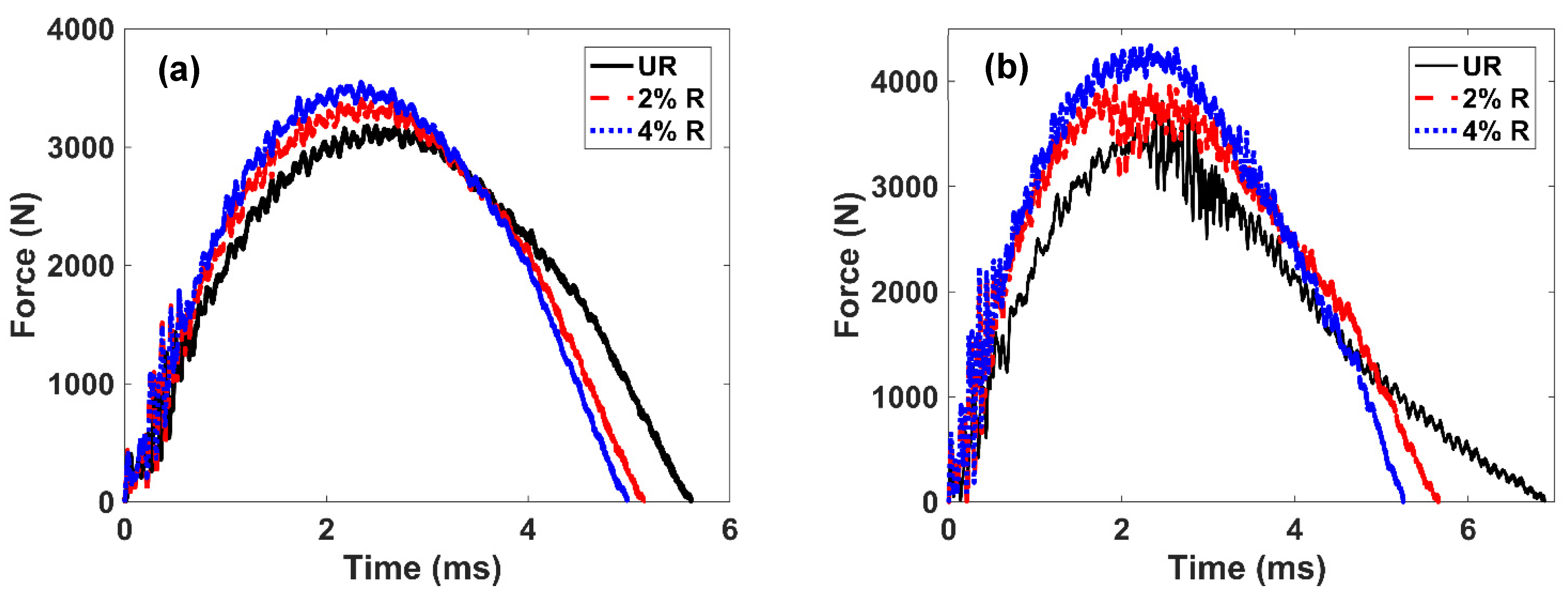
Representative force histories associated with 7.5 J and 12.5 J impact energies are shown in Figure 1a,b, respectively. The bell-shaped curves exhibit higher undulation when rising compared to when they fall. The prominent peaks at the start suggest damage initiation and/or damage propagation in the laminate. The force associated with the first peak is tabulated in Table 1 and was identified as the first failure in the laminate [8]. While the first failure load increased with increasing impact energy, the reinforcement appears to have had no influence on the failure initiation (see Figure 1). The impact force reduced to zero when the impactor rebounded and ceased to be in contact with the laminate. The plots show that the contact duration of the impactor decreased as the reinforcement in the laminate increased. In addition, the maximum force sensed by the laminate increased with increasing reinforcement. The force histories associated with the 12.5 J impact (Figure 1b) exhibit large oscillations around the peak force in the unreinforced and 2% R laminates. This indicates delamination, with significant damage to the laminate. On the contrary, a relatively smoother transition from the ascending to the descending part of the curve suggests a higher resistance to damage in the case of the 4% R laminates.
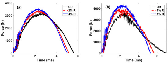
Figure 1.
Force time histories at (a) the 7.5 J loading and (b) the 12.5 J loading.

Table 1.
Low-velocity impact and post-impact flexural characteristic parameters.
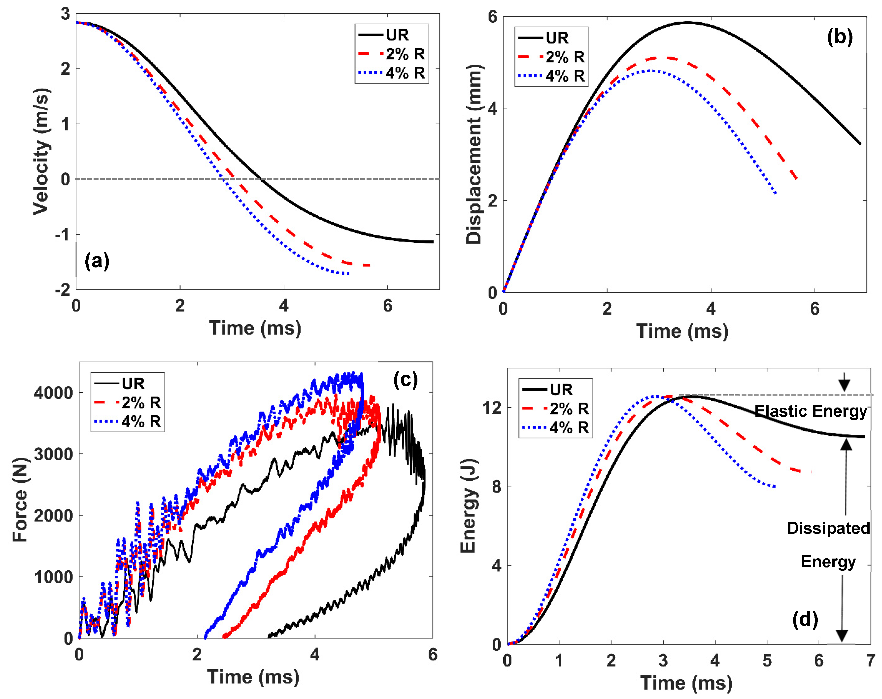
The velocity and displacement histories, determined by means of Equations (1) and (2), are shown in Figure 2a,b, respectively. The plots are associated with the 12.5 J impact energy. While the velocity at t = 0 represents initial impact velocity, the time instant associated with zero velocity corresponds to when the impactor begins to rebound. The velocity plots show that the rebound velocity consistently increased as the reinforcement in the laminate increased, which indicates an increasing elastic energy component during the impact events. The displacement histories (Figure 2b) exhibit skewed bell-shaped curves with increasing maximum displacement as the filler content in the laminate decreased. The force vs. displacement plots are illustrated in Figure 2c. The areas enclosed within the loading–unloading curves represent energy dissipated during impact. The plots show that the maximum force increased with increasing filler content, whereas the maximum displacement decreased with increasing filler volume fraction. The permanent displacement associated with zero force during unloading decreased with increasing filler content, which suggests an increase in the damage resistance of the laminates. The energy dissipated during impact, calculated by means of numerical integration, is reported in Table 1. While dissipated energy increased with increasing impact energy (Singh and Kitey [15]), it decreased with increase in the chopped fiber volume fractions.
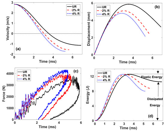
Figure 2.
Various impact performance parameter curves at 12.5 J impact: (a) force–displacement; (b) velocity–time; (c) displacement–time; (d) energy–time.
The energy absorbed by the laminates is plotted against time in Figure 2d. After attaining the maximum value, the curves monotonically decrease until a plateau value is attained. The plateau value signifies the energy dissipated in the failure process. The elastic energy stored in the laminate system was determined by the difference between the maximum energy and the dissipated energy (with an assumption of other frictional dissipation being negligible). For the 7.5 J impact, only a marginal increase in elastic energy was noted with increasing chopped fiber content. On the other hand, for the 12.5 J impact, the elastic energy stored in the laminates increased by 23% and 66% in the 2% R laminates and 4% R laminates, respectively.
3.2. Microscopic Impact Damage Characterization
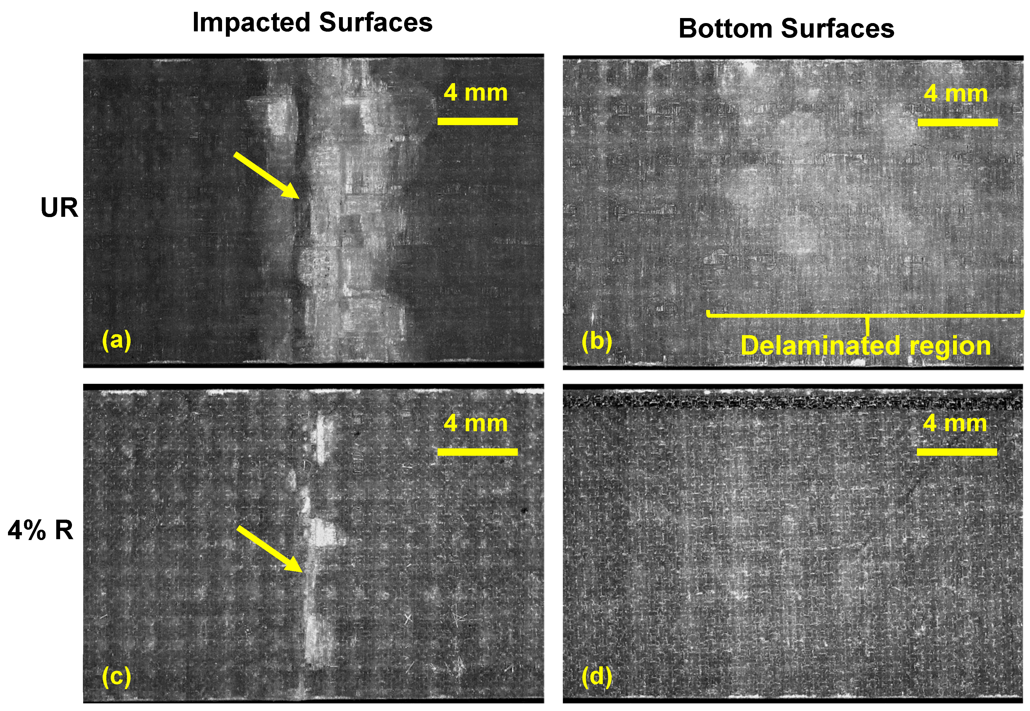
The surfaces of impacted beam samples were imaged using optical microscopy to analyze the extent of damage, as illustrated in Figure 3. The impact locations are marked by arrows. Figure 3a, b show the damage on the impacted surface and on the back surface, respectively, for the 12.5 J impact energy case. The bright area near the impacted site in Figure 3a suggests localized micro-buckling at the top lamina due to compressive stress. On the other hand, the bright area at the back face indicates delamination failure. A relatively smaller damage area was observed for the reinforced laminate at the impacted face as well as at the back face, as depicted in Figure 3c,d, respectively. At lower impact energies, less damage near the impact line, as well as on the back surface, was noticed.
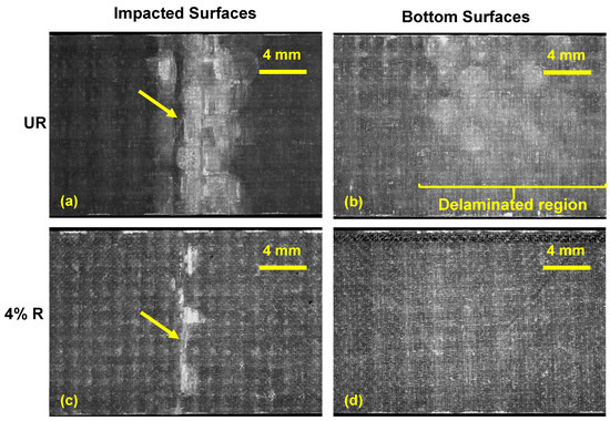
Figure 3.
Visible impact damage to the impacted and bottom surfaces of (a,b) the unreinforced specimen and (c,d) the 4% chopped fiber-reinforced specimen.
3.3. Analysis of Residual Flexural Properties
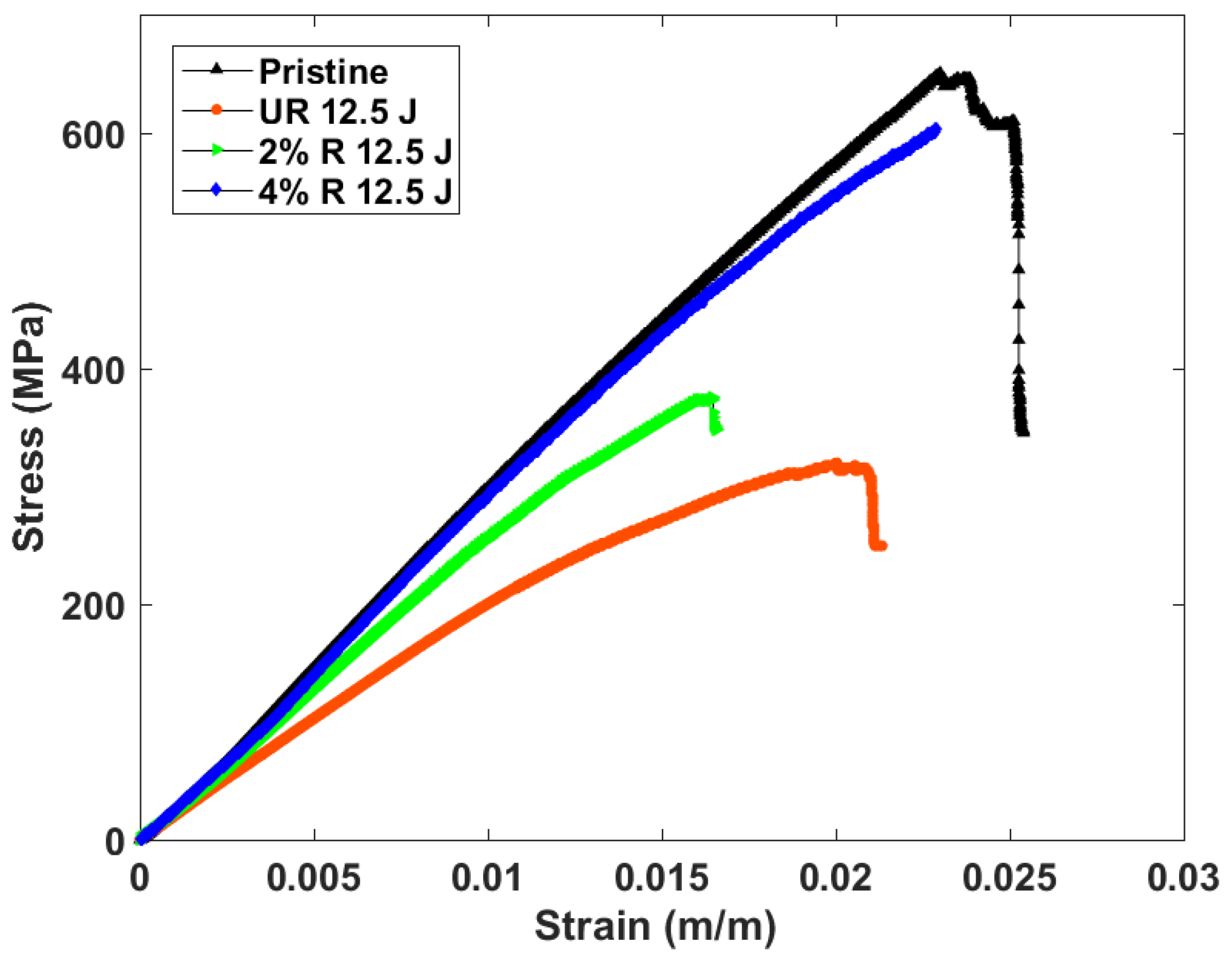
The flexural stress vs. strain curves associated with the specimens impacted with 12.5 J energy are shown in Figure 4. For comparison, the plot associated with the pristine UR specimen is also included in the figure. Flexural moduli and strengths were calculated for all the samples and they are tabulated in Table 1. In the case of the pristine samples, only a marginal increase in flexural strength was noted when the filler content was increased, whereas the associated flexural modulus remained nearly the same. The plots show that post-impact flexural modulus and strength decreased with increasing impact energy in all the laminates. Figure 4 and Table 1 suggest higher residual flexural moduli and strengths for the filler reinforced cases. While at 7.5 J impact energy, the increase in the residual properties was only marginal, a 32% and 68% rise in flexural modulus and strength, respectively, was observed for the 12.5 J loading case. Interestingly, the laminate prepared with 4% filler reinforcement exhibited nearly the same flexural strength and stiffness values as noted for the pristine UR specimens.
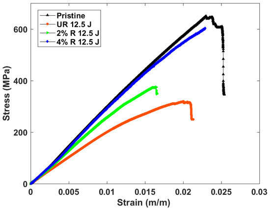
Figure 4.
Stress–strain plot of various laminate samples, including an unimpacted neat epoxy sample.
4. Conclusions
In this study, the low-velocity impact behaviour and post-impact residual characteristics of modified-matrix glass fabric laminated composites were analysed. Sixteen plies of plain weave glass fibers were used as a primary reinforcement, while the matrix was modified by mixing it with 1/4” long chopped glass fibers at 2% and 4% volume fractions. Laminates prepared with neat epoxy matrix were also investigated. Beam samples machined from the laminates were impacted symmetrically at the mid-span with 7.5 J and 12.5 J energies by employing a V-shaped impactor. The data acquired from the instrumented tup suggest that the impact resistance as well as the elastic response of the laminates increased with increasing chopped fiber content. While the effect of chopped fiber was marginal at lower impact loadings, at 12.5 J a 17% reduction in dissipation energy was noted for the 4% reinforced laminate. Microscopic analysis suggested severe damage to the unmodified-matrix laminate specimens, especially at higher impact energies. Impact resistance increased with an increase in chopped fiber content in the matrix, with reduced damage. At low impact energies and with smaller filler contents, the quasi-static symmetric four-point bend tests exhibited marginal improvements in post-impact flexural characteristics. On the other hand, at the 12.5 J impact energy in the 4% R laminate case, a 32% and 68% increase in flexural modulus and strength, respectively, was noted. Micrographic analysis exhibited a good correlation with crucial laminate performance parameters.
Author Contributions
Conceptualization, M.K.S. and R.K.; methodology, M.K.S.; validation, M.K.S. and R.K.; formal analysis, M.K.S.; investigation, M.K.S.; resources, R.K.; data curation, M.K.S.; writing—original draft preparation, M.K.S.; writing—review and editing, R.K. and M.K.S.; visualization, R.K.; supervision, R.K.; project administration, R.K.; funding acquisition, R.K. All authors have read and agreed to the published version of the manuscript.
Funding
This research received no external funding.
Institutional Review Board Statement
Not applicable.
Informed Consent Statement
Not applicable.
Data Availability Statement
The data presented in this study are available on request from the corresponding author. The data are not publicly available due to continuation of the work.
Conflicts of Interest
The authors declare no conflict of interest.
References
- Tang, Y.; Ye, L.; Zhang, Z.; Friedrich, K. Interlaminar fracture toughness and CAI strength of fibre-reinforced composites with nanoparticles—A review. Compos. Sci. Technol. 2013, 86, 26–37. [Google Scholar] [CrossRef]
- Xu, X.; Zhou, Z.; Hei, Y.; Zhang, B.; Bao, J.; Chen, X. Improving compression-after-impact performance of carbon–fiber composites by CNTs/thermoplastic hybrid film interlayer. Compos. Sci. Technol. 2014, 95, 75–81. [Google Scholar] [CrossRef]
- Richardson, M.O.; Wisheart, M.J. Review of low-velocity impact properties of composite materials. Compos. Part A Appl. Sci. 1996, 27, 1123–1131. [Google Scholar] [CrossRef]
- Cantwell, W.J.; Morton, J. The impact resistance of composite materials—A review. Composites 1991, 22, 347–362. [Google Scholar] [CrossRef]
- Kim, J.K. Methods for improving impact damage resistance of CFRPs. Key Eng. Mater. 1998, 141, 149–168. [Google Scholar] [CrossRef]
- Zhang, X.; Hounslow, L.; Grassi, M. Improvement of low-velocity impact and compression-after-impact performance by z-fibre pinning. Compos. Sci. Technol. 2006, 66, 2785–2794. [Google Scholar] [CrossRef] [Green Version]
- Mouritz, A.P. Review of z-pinned composite laminates. Compos. Part A Appl. Sci. 2007, 38, 2383–2397. [Google Scholar] [CrossRef]
- Hu, Y.; Liu, W.; Shi, Y. Low-velocity impact damage research on CFRPs with Kevlar-fiber toughening. Compos. Struct. 2019, 216, 127–141. [Google Scholar] [CrossRef]
- Yuan, B.; Ye, M.; Hu, Y.; Cheng, F.; Hu, X. Flexure and flexure-after-impact properties of carbon fibre composites interleaved with ultra-thin non-woven aramid fibre veils. Compos. Part A Appl. Sci. 2020, 131, 105813. [Google Scholar] [CrossRef]
- Santiuste, C.; Sánchez-Sáez, S.; Barbero, E. Residual flexural strength after low-velocity impact in glass/polyester composite beams. Compos. Struct. 2010, 92, 25–30. [Google Scholar] [CrossRef] [Green Version]
- Balakrishnan, V.S.; Wartig, K.; Tsombanis, N.; Seidlitz, H. Influence of processing parameters on the impact behaviour of glass/polyamide-6 composite. Compos. B Eng. 2019, 159, 292–299. [Google Scholar] [CrossRef]
- Hart, K.R.; Chia, P.X.; Sheridan, L.E.; Wetzel, E.D.; Sottos, N.R.; White, S.R. Comparison of compression-after-impact and flexure-after-impact protocols for 2D and 3D woven fiber-reinforced composites. Compos. Part A Appl. Sci. 2017, 101, 471–479. [Google Scholar] [CrossRef]
- ASTM D7136/D7136M-12; Standard Test Method for Measuring the Damage Resistance of a Fiber-Reinforced Polymer Matrix Composite to a Drop-Weight Impact Event. ASTM International: West Conshohocken, PA, USA, 2012.
- ASTM Standard D6272–10; Standard Test Method for Flexural Properties of Unreinforced and Reinforced Plastics and Electrical Insulating Materials by Four Point Bending. ASTM International: West Conshohocken, PA, USA, 2010.
- Singh, M.K.; Kitey, R. Enhancing Dynamic Fracture Behavior of Laminated Composite by Short Fiber Reinforcement. In Advances in Structural Integrity; Jonnalagadda, K., Alankar, A., Balila, N.J., Bhandakkar, T., Eds.; Springer: Singapore, 2022; pp. 243–253. [Google Scholar]
Publisher’s Note: MDPI stays neutral with regard to jurisdictional claims in published maps and institutional affiliations. |
© 2022 by the authors. Licensee MDPI, Basel, Switzerland. This article is an open access article distributed under the terms and conditions of the Creative Commons Attribution (CC BY) license (https://creativecommons.org/licenses/by/4.0/).

