Abstract
Solar cells based on the hybrid perovskite absorbers had shown very high growth of their conversion efficiency almost reaching to the Shockley–Queisser limit during last decade. However, low stability prevents to widely use them in industry and in everyday life. Possible reasons and pathways to remedy of instability and degradation of the perovskite solar cells are considered in this review. Specific attention was paid to the thermodynamical analysis of the hybrid perovskite absorber.
1. Introduction
The significant increase in the world’s population, coupled with an increase in industrial consumption in recent decades, requires the production and supply of huge amounts of electrical energy. Traditional energy sources are no longer enough for humanity. Gas, coal, and oil are rapidly depleting. Research shows that in about 50 years these sources will be exhausted. Therefore, more than ever, there is a strong push to switch to renewable energy.
The sun is an inexhaustible source of energy. One of the most effective ways to use solar energy is the photovoltaic effect, which allows us to directly convert solar energy into electricity. However, there are several problems that prevent the widespread use of solar cells: these include the high cost of solar cells and the complexity of their manufacture, relatively low conversion efficiency, and very low stability and service life of these cells.
Over the past decade, significant reductions in the cost of solar cell production have been achieved thanks to the enormous efforts of scientists and engineers [1]. Also, the level of solar cell efficiency (power conversion efficiency or PCE) has almost reached maximum values restricted by the well-known Shockley–Queisser limit [2,3]. There are many different types of solar cells, which can be categorized by generations. First-generation solar cells use conventional crystalline silicon technologies of two types: monocrystalline and polycrystalline. These solar cells have been in operation since the early days of the solar industry to this day. Their record efficiency reaches 26.1% for a monocrystalline silicon solar cell under single-sun conditions, 24.4% for a multicrystalline solar cell, and 27.4% for a monocrystalline gallium arsenide [4,5]. Second-generation solar cells consist of thin-film solar cells based on silicon, gallium arsenide, kesterite, and chalcopyrite [6]. Also included in the second generation are dye-synthesized [7] and organic photovoltaic cells [8]. Third-generation solar cells represent a new phase of development in photovoltaic technology. These solar cells include various new technologies such as heterojunction structures [9], tandem and multijunction systems [10], solar cells utilizing the nano-dimensional structures [11] and perovskite solar cells [12], which achieved the record power conversion efficiency of 26%.
Solar cells based on perovskite absorbers deserve special attention. During the last decade, these solar cells have demonstrated a dramatic increase in their power conversion efficiency from 2% to 25% at a relatively low cost of production [13]. Figure 1 illustrates this achievement [14]. While the results of other technologies remain roughly constant, the efficiency of perovskite solar cells continues to increase. The maximum PCE of perovskite solar cells (PSC) has reached 27.0% for a single cell and 30.1% for a perovskite tandem cell. Considering these excellent photophysical properties, this material, perovskite, is suitable not only for solar cells, but also for LEDs, photodiodes, photodiode detectors, and various types of lasers [15]. Obviously, due to these excellent results and the relatively cheap fabrication process, many researchers have turned their attention to perovskite solar cells.
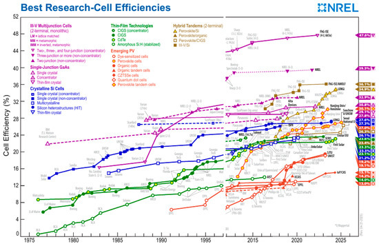
Figure 1.
Efficiency records for perovskite photovoltaic cells compared to other photovoltaic technologies, with current records of 27.0% for single junction perovskite devices and 30.1% for tandem perovskite–silicon devices (This plot is courtesy of the National Renewable Energy Laboratory, Golden, CO, USA, as of June 2025) [14].
Unfortunately, under real operating conditions, PSCs exhibit degraded photovoltaic performance, low stability, and short lifetime, which together hinder the commercialization of perovskite solar cells. Therefore, in this work, we will examine some conditions that affect the properties of PSCs and look for ways to improve their stability.
2. Short Historical Sketch
The first mention of perovskite was described in 1830 by the geologist G. Rose. He described the mineral calcium titanate (CaTiO3) and named it after the Russian mineralogist Lev Perovsky. Subsequently, all minerals with the crystalline structure ABX3 were called perovskites [16]. In this structure, A represents a larger organic or metal cation (for example, Ca2+), B is a smaller metal cation (such as Ti4+), and X is the halogen (chlorine, bromine, iodine, or fluorine). When we have a metal atom in the form of a cation A together with a heavy metal B and a halogen, we have inorganic perovskites. Some of the most studied inorganic perovskites have been barium titanate, BaTiO3, and calcium titanate. These are two perovskite materials that have been studied extensively for their ferroelectric properties. Various types of materials have been made using these two perovskite structures [17]. Later, researchers discovered that by appropriately replacing the inorganic cation, its structure is changed, and, therefore, it is always possible to fabricate a perovskite structure with an adjustable band gap. After this was realized, the application of perovskite in the field of optoelectronics began.
3. Crystal Structure and Electronic Properties of Perovskites
Perovskites are a widespread class of minerals that account for half of the total mass of planet Earth [17]. These materials are the most available in the world. An ideal perovskite represents a perfect face-centered cubic 3D structure as shown in Figure 2. Each crystal cell consists of B-metal ions 6-fold octahedrally coordinated with anionic species (halides, oxides, sulfides, nitrides, etc.) and presented as [BX6]4− or [BO3]2− frameworks or octahedrons (Figure 2b). The A-cations are accommodated in the cuboctahedral void formed by the four shared B-metal octahedra (Figure 2c).
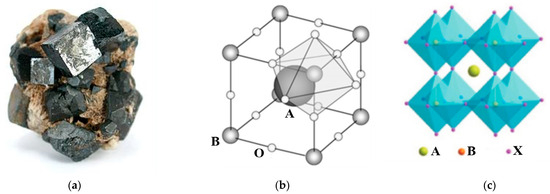
Figure 2.
Crystal structure of the ideal perovskite: (a) a natural mineral CaTiO3 (Wikipedia), (b) a schematic arrangement of components within a crystal cell [16], (c) a reconstructed cubic face-centered structures [18].
The ion sizes of ions significantly affect the stability and distortion in the crystal structure of perovskites, which in turn changes their physical, optical, and magnetic properties [19]. The relationship between geometrical dimensions of ions in the crystal cell is described by the Goldschmidt tolerance factor, which defines the degree of distortion, stability, and formability of perovskite material [20].
where RA, RB, and RX are the ionic radii of A, B, and X components, respectively. The tolerance factor of an ideal cubic perovskite should be equal to t = 1 [21]. All deviation in the tolerance factor leads to the formation of a distorted phase or perovskites with reduced dimensional symmetry, influencing the optical and electrophysical properties of the material. The relation between the sizes of different fragments of the crystal structure is very important for the stability of the system [22]. The Goldschmidt tolerance factor is determined by the average ionic radii of all the constituent components. As the temperature increases, the range of atomic oscillations relative to their average state will increase. This means that these radii will increase with increasing temperature. This can lead to distortion of the crystal structure and subsequent segregation of the complex substance into its components. Of course, these processes will be accompanied by a change in the thermodynamic parameters of the materials.
Typical perovskite, CaTiO3, represents a chemically stable n-type semiconductor with a bandgap of 3–3.5 eV [23]. The electronic band structure plays an important role in the stability and opto-electronic properties of perovskite material. In the case of oxide perovskite CaTiO3, a mixture of titanium frontier d orbitals and oxygen 2p orbitals forms an electronic band structure near the Fermi level. The highest occupied molecular orbital (HOMO) is characterized by nonbonding 2p atomic orbitals of oxygen, which form the valence band maxima. The lowest unoccupied molecular orbital (LUMO) is characterized by antibonding 2p-d molecular orbitals of oxygen and transition metals (Ti), which constitute the conduction band minima. Due to the larger electronegativity difference between titanium and oxygen atoms, the covalency in the bond is reduced, which reduces the charge transfer between oxygen and titanium atoms. So, they represent wide-bandgap semiconductor, which decreases the use of oxide perovskite materials in photovoltaic applications.
As mentioned above, the halide perovskites exist together with oxide perovskites. They have the same structure ABX3. Here, the 6s orbitals of the metal (for example Pb) overlap with the p orbitals of the halogen, resulting in the formation of bonding and antibonding molecular orbitals. Accordingly, the antibonding molecular orbitales constitute the HOMO and the same orbitals of Pb and halide ions account the LUMO part of the band structure. The effective overlapping of orbitals along the octahedron of the metal-halide framework [BX6]4− leads to ease formation of photoexcited electrons and holes with low effective mass, which facilitate the high mobility in band transport. These effects positively affect the optical and photovoltaic properties of halide perovskite materials [24].
4. Perovskite Solar Cells
Perovskite solar cells have attracted the high attention through last decade due to high efficiency, low cost, and bandgap tunability. Figure 3 illustrates two basic planar photovoltaic constructions, regular and inverted structures [25,26].
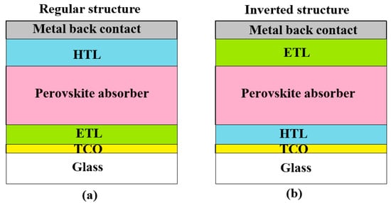
Figure 3.
Two basic planar structures of perovskite solar cells: (a) the regular structure, (b) the inverted structure.
Here, a transparent conductive oxide (TCO) provides collection of charge carriers, an electron transport layer (ETL), and a hole transport layer (HTL) to realize the charge separation [26]. A perovskite absorber represents an intrinsic semiconductor layer arranged between two transport layers providing opposite charge carriers moving and collection. Thus, a perovskite planar solar cell represents the usual n-i-p or p-i-n structure.
For the photovoltaic effect to occur, the device must provide a two-stage process [27]. At the first stage, light is absorbed with the formation of free pairs of charge carriers (electron and hole) or bound pairs—excitons with a sufficiently low binding energy. At the second stage, charges are separated, which allows the resulting electrons to be collected and used in the external load circuit. The first step of the photovoltaic process, absorption of coming photons, is provided by suitable bandgap width of the absorbing material. The second step, the charge separation, is different in various construction of photovoltaic devices. Separation of charges in conventional PN diode-type photovoltaic cells occur due to a strong nature built-in electrical field appearing in the semiconductor junction. In the case of P-doped-intrinsic-N-doped (PIN) structures, the intrinsic zone is attached to the depletion zone of the junction and increases the built-in electrical field. However, separation of charges in photovoltaic elements based on such materials as perovskites, occurs by another way. A built-in electrical field here is formed due to contact potential difference between the intrinsic absorber layer and bordering ETL and HTL, like to the usual PIN structure. Figure 4 illustrates an operation principle of the perovskite solar cell.
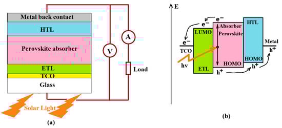
Figure 4.
Perovskite solar cell application for the electricity producing: (a) Principal electrical connection of the PSC with a load, (b) Principal scheme of generation and separation of electrical charges.
Under illumination, a perovskite material absorbs coming photons with excitation free mobile charge carriers [28]. The excitonic binding energy in perovskites is low and comparable to the environment thermal energy. Excitons easily dissociate and produced charge carriers which have high mobility and can travel to the LUMO of the ETL and to the HOMO of the HTL, as shown in Figure 4b. From the ETL and HTL, the electrons and holes, respectively, move through to the electrode layers to generate an electric current in an external load as shown in Figure 4a.
Perovskites with the same general formula ABX3 include large class of materials from completely inorganic to combined organic–inorganic systems. Their complex structure (see Figure 2b,c) enables incredible structure variety. Each site of the perovskite cell may be occupied by different elements, for example, the site A can take 24 elements from the periodic table and site B can occupy 50 elements [28]. By variation in elements in the sites of the perovskite structure, we can change the crystalline form, dimensions of the cell, and their electrophysical and optical properties. Also, the site A may be occupied by several cations or differently charged ions enabling the fine tuning of the cell properties. The most studied perovskites used for photovoltaic applications are hybrid organic–inorganic halide perovskites. This class of perovskites is expected to be stable with a tolerance factor in the range of 0.813–1.107 [26]. The site A in these perovskites is usually occupied by such cations as methylammonium (CH3NH3+) or formamidinium (CH(NH2)2+). Fully inorganic perovskites include alkaline metals in the site A, for example, cesium (Cs+) and post-transition metals such as lead (Pb2+) or tin (Sn2+) in the site B. The hybrid organic–inorganic material CH3NH3PbI3 (MAPbI3) is one of the most studied perovskites due to its excellent optoelectronic properties, such as low exciton binding energy (∼16 meV), direct–indirect band gap energy of 1.51 to 1.55 eV, long diffusion length for electrons and holes (0.1 to 1 μm), and high electron and hole charge mobility [29]. PSCs have great potential due to their high efficiency and low cost. However, their long-term stability remains one of the major challenges for commercial viability. Several factors contribute to the instability of perovskite solar cells:
- Perovskite materials are highly sensitive to moisture. Exposure to water or high humidity can cause the perovskite layer to degrade or decompose, leading to a loss of performance. This is especially true for lead-based perovskites, where water can cause the material to undergo phase transitions or dissolve completely.
- Perovskite materials can be unstable at elevated temperatures, especially in the presence of high light intensity. The crystal structure can degrade, resulting in reduced PCE and long-term instability. This makes perovskite cells less suitable for environments with high temperatures.
- Prolonged exposure to sunlight can lead to light-induced degradation of perovskite materials. This phenomenon, often referred to as photo-induced phase segregation or photo-degradation, causes the perovskite layer to lose its structural integrity, resulting in performance loss over time.
- Perovskite materials can exhibit ion migration, especially under electric fields or during operation. The movement of ions (like lead or halides) within the perovskite structure can lead to defects, resulting in degradation of the material and loss of device performance. This issue can also contribute to hysteresis in current-voltage characteristics.
- The materials used for electrodes in perovskite solar cells, such as gold or silver, can degrade over time due to chemical reactions with perovskite or other layers. This can reduce the electrical contact and lead to performance degradation. Moreover, certain hole transport layers or electron transport layers may also degrade under operational conditions, contributing to instability.
- Perovskite materials can experience changes in their crystal structure under certain environmental conditions (e.g., temperature, humidity). These structural changes can cause phase transitions that reduce the performance of the cell, making them less stable over long periods.
- Perovskite solar cells are composed of multiple layers, and the interfaces between these layers can sometimes degrade over time. This degradation can result in charge recombination at the interfaces, leading to a decrease in efficiency.
- Impurities in the perovskite material or during the fabrication process can lead to the formation of unwanted phases or defects that can cause degradation. These impurities can arise from solvents, metal contamination, or residual chemicals.
For example, we want to show the influence of the interface between the hybrid organo-inorganic perovskite absorber and the organic hole transport layer on the behavior of the system. As is known, the solution-processed perovskite film is a polycrystalline structure, which produces many structural defects that affect the enhanced recombination [30]. X. Qi and colleagues experimentally studied hybrid organo-inorganic solar cells based on formamidinium lead-iodide perovskite equipped with a hole transport layer made of lithium-doped Spiro-OMETAD [31]. To reduce the influence of the interface problems between these two layers, the authors introduced a 1,4-dithiane layer into this interface. This intermediate layer neutralizes the crystal defects at the interface and prevents the diffusion of lithium ions into the perovskite. As a result, the photoelectric conversion efficiency reached 23.27%, and the system stability was significantly improved: the normalized value of photoelectric conversion efficiency increased by about three times after 500 h of operation at an ambient temperature of 85 °C.
The instability of perovskite solar cells conditioned by mentioned above reasons remains one of the main challenges for scaling up and commercializing this technology. As can be seen from the above, the main degradation mechanisms of PSC are spontaneous chemical reactions between the materials comprising the perovskite and the electron and hole transport layers and reagents such as oxygen, halogens, and water. Incoming photons absorbed by the photovoltaic cell can accelerate these reactions and enhance the degradation effect. Moreover, organic monovalent cations such as MA+ and FA+ suffered from poor stability under photo, thermal and moisture stress [18] and require replacement with more stable inorganic cations, for example, Cs+. Figure 5 illustrates the efficiency behavior for two perovskite solar cells distinguished by different monovalent cations, organic MA+ and inorganic Cs+. These measurements were taken in ambient air at a relative humidity (RH) of 60–70%, every couple of days for two weeks. Between measurements, the devices were stored in dry air (in the dark) at RH ~15–20%.
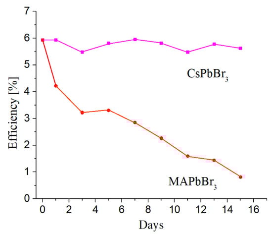
Figure 5.
Behavior of perovskite solar cells based on organic and inorganic cations as a function of time [18].
As shown in Figure 5, the PSC built as a full-inorganic system is more stable then mixed organic–inorganic one. These results were confirmed by comparative thermodynamic analysis of the stability of hybrid halide perovskites at room temperature using MAPbI3 and fully inorganic CsPbBr3 as an example [32].
5. Analysis of Thermodynamical Sustainability of Perovskite Solar Cells
5.1. Analysis of the Absorber MAPbI3 Behavior in the Narrow Temperature Range
The processes occurring in perovskite solar cells under the influence of photo, thermal and humidity factors require thermodynamic analysis and assessment of the probability of spontaneous chemical and structural reactions in the material. Such an approach can help in choosing suitable materials for both the perovskite absorber and the electron and hole transport layers. In this regard, it is of interest to use the Ellingham diagram method to assess the possible behavior of perovskite solar cells. This method was proposed by Ellingham in 1944 to study metallurgical processes involving oxides and sulfides [33]. The degradation mechanism of halide perovskites should also be studied considering their thermodynamic behavior.
Degradation factors can act together and separately on PSC components. For example, MAPbI3 can segregate on components at 85 °C without influence oxygen or moisture. The suitable chemical reactions with the emergence of new phases have been shown by many researchers and are presented in the papers [32,34,35]:
CH3NH3PbI3(s) → CH3NH2↑ + HI↑ + PbI2↓,
CH3NH3PbI3(s) → CH3I↑ + NH3↑ + PbI2↓,
CH3NH3PbI3(s) → CH3NH3I↑ + PbI2↓,
Thermochemical degradation of MaPbI3 on components according to Equations (2) and (3) at elevated temperature of 85 °C without moisture and oxygen was observed and described by S. Mazumdar et al. [33]. Thermodynamic reasons for this degradation were studied by D. Heine et al. [34], who considered all three reactions (Equations (2) and (4)). They used the molecular dynamics modeling method and the density functional approximation and studied the possibility of applying computational models to predict the thermodynamic stability of hybrid perovskites. Unfortunately, their main efforts were aimed at studying the calculation methods and their comparison. E. Tenuta et al. [32] considered the reaction according to Equation (4) from the point of view of assessing the changes in Gibbs free energy between reactants and products. The analysis carried out in this work shows that the chemical stability of MaPbI3 perovskite is fragile, and the equilibrium can be easily shifted by changing the environment.
Characterization of thermodynamic system usually can be provided using the Gibbs free energy variation (ΔG) of a reaction. A negative value for ΔG indicates that a reaction can proceed spontaneously without external inputs, while a positive value indicates that it will not. The equation for the Gibbs free energy is as follows:
where ΔH is the enthalpy, T is absolute temperature, and ΔS is entropy. The enthalpy (ΔH) is a measure of the actual energy that is liberated or evolved when the reaction occurs (the “heat of reaction”). If it is negative, then the reaction gives off energy, while if it is positive the reaction requires energy. The entropy (ΔS) is a measure of the change in the possibilities for disorder in the products compared to the reactants. For example, if a solid (an ordered state) reacts with a liquid (a somewhat less ordered state) to form a gas (a highly disordered state), there is normally a large positive change in the entropy for the reaction.
The Gibbs free energy is a function of the state of the system. Thus, the change in the Gibbs free energy occurs due to a reaction in the system, and if the thermodynamic parameters of the system are related to the standard state, the result will be the standard free energy of the reaction. From this point of view, the balance between the thermodynamic parameters, enthalpy and entropy, becomes very important and determines the possibility of a spontaneous reaction. To estimate a type of the reaction: exergonic (ΔG < 0) or endergonic (ΔG > 0) and exothermic (ΔH < 0) and endothermic (ΔH > 0), Equation (5) must be expanded by the following way:
Calculation results will be substituted in Equation (5) to define the reaction type for the defined reaction temperature in Kelvins. The effect of moisture on the stability of the perovskite absorber was excluded from our consideration because water cannot contact the absorber layer in PSC. The absorber layer is sandwiched between the electron and hole transport layers, which in turn are also sealed by the substrate and the top encapsulating coating. Calculation results are presented in Table 1. Initial thermodynamic values of enthalpy and entropy for MAPbI3 and its components of decomposition are taken from the reference sources. Calculation of the free Gibbs energy variation according to Equation (5) was performed for the ambient temperature of 85 °C.

Table 1.
Calculation of the thermodynamical stability of MAPbI3.
The calculation of the free Gibbs energy variation, presented in Table 1, shows that the methylammonium lead iodide is the thermodynamically unstable substance and is prone to spontaneous decomposition. The most probable reaction is the first type with the relies of gas phases such as hydrogen iodide and methylammonium. Thus, the decomposition of perovskite MAPbI3 is a nature process that does not require of the ambient influence from air, water, light, or heat. Our conclusions are confirmed by calculations based on experimental data [35,40]. Moreover, calculation of the thermodynamic behavior of various hybrid and fully inorganic perovskites MAPbI3, FAPbI3, CsPbBr3, etc. showed that only the fully inorganic compound is stable compared to the hybrid systems [32]. In the case of CsPbBr3, unlike MAPBI3, the enthalpy of the decomposition reaction is positive, and this substance does not undergo spontaneous decomposition. This is confirmed by an experiment comparing these two perovskites. M. Kulbak et al. [40] prepared MAPbBr3 and CsPbBr3 and compared their properties under the same conditions. Therefore, to create a stable and sustainable perovskite absorber, it must be prepared as a completely inorganic substance and organic cations such as methylammonium or formamidinium should be changed on the inorganic cation from the family of alkaline, earth-alkaline or rare metal cations (Cs+, K+, Br+, Ca2+, Ba2+, Eu2+, Yb2+, etc.) [28,41]. Of greatest interest are such completely inorganic perovskites as CsPbCl3 or lead-free CsSnCl3 or a new compound from the same family KCuCl3. All these perovskites have a Goldschmidt tolerance factor in the range of 0.9–1.1 and represent stable structures.
5.2. Analysis of the Interfaces Between Absorber and Charge Transport Layers Behavior
The charge transport layers, ETL and HTL, perform two main functions: separating the generated charge and its collecting into the external circuit. These layers should carry suitable charge carriers and not react with the perovskite absorber and electrodes. To ensure these properties, the charge transport layers should be chemically stable, protect the perovskite absorber layer from ion diffusion, and provide high mobility of suitable charge carriers. Moreover, it has been shown that the nature of the contact between the charge transport layer and the perovskite absorber can significantly affect the dynamical response of charge accumulation at the interface [42].
The ETL plays the role of electron transport and hole blocking. A suitable ETL should have an energy band position matching the perovskite material. The conduction band position should be slightly below the conduction band minimum of the perovskite layer to facilitate electron injection, while the valence band should be in a deeper position to effectively block holes and have high electron conductivity to ensure electron transport and collection [43]. Typically, the electron transport layer consists of a thin film of a wide-bandgap N-type semiconductor oxide such as TiO2, SnO2 or ZnO and the like, doped with a suitable metal. To ensure high conductivity, these oxides are doped with a metallic, organic, or complex compound. Application of organic and hybrid compounds help enrich the very sufficient efficiency of solar cells, but they do not provide necessary service life due to chemical instability and rapid degradation. Therefore, the electron transport layers should be fully inorganic [44].
The HTL is located between the perovskite and the upper electrode. Its role is to quickly extract the generated holes. It also blocks the moving electrons to protect the cell from short circuits and additional recombination of charge carriers. The energy level of the HTL material must be slightly higher than the maximum of the valence band of the perovskite material, which ensures the transport of holes. The transit time of charge through the HTL is one of key’s parameters influencing on the open circuit voltage and the fill factor of the perovskite solar cell. Thus, the hole conductivity plays a crucial role on the PSC behavior. A variety of materials can be used as HTL, for example, in the theoretical work of M.K. Hossain et al. [45], 12 different compounds were used and compared as HTLs. The small molecule 2,20,7,70-tetrakis[N,N-di(4-methoxyphenyl)amino]-9,90-spirobifluorene (spiro-OMeTAD) with the bandgap of 3 eV and the hole mobility of ~2.16·10−3 cm2/V·s and the polymer poly[bis(4-phenyl)(2,4,6-trimethylphenyl)amine] (PTAA) are recognized as the most effective organic materials used in the role of HTL in the hybrid organic–inorganic lead halide PSC [46]. Due to relatively low hole conductivity and mobility, these HTLs are usually doped by additional metal and organic dopants. As is known, doping is a well-developed method for improving the conductivity and transition time of semiconductors [47].
Unfortunately, organic HTLs suffer from many disadvantages related to temperature effects, poor adhesion between HTL and perovskite layer, and excess defects at the interface. For example, doped spiro-OMeTAD decomposes at 85 °C to form pinholes [48]. HTL prepared from PTAA behaves better than spiro-OMeTAD at the interface with perovskite absorber but suffers from temperature and metal ion diffusion in the same way as spiro-OMeTAD [49]. It was found that iodine doping increases the high-temperature stability of spiro-OMeTAD HTLs, but it leads to perovskite degradation due to iodine extraction from perovskite and subsequent HTL degradation [50]. Thus, our analysis leads to the recognition that organic HTLs cannot provide long-term stable performance of the PSCs. It should be added that the methods for preparing organic HTLs and hybrid organo-containing perovskites such as MAPbI3 are usually based on solutions—processable fabrication. However, thin films prepared by these methods tend to be rough and defective containing various imperfections such as pinholes and burs [50]. Therefore, to increase the PSCs stability and sustainability, wet chemical processes must be excluded from the successful technology.
So, inorganic p-type compounds with the high hole mobility should be considered in the role of the hole transport layer materials. These materials can include an inorganic kesterite HTL consisting of Cu2BaSnS4 (CBTS) with the bandgap of 1.9 eV and the hole mobility of ~10 cm2/V·s [46], thin film of Cu2O with the bandgap of 2.17 eV and the hole mobility of ~80 cm2/V·s [25], p-type thin films of VOx with the bandgap of 0.9 eV, defined by the preparation method [51], and many others.
6. Possibility and Prospects
Perovskite solar cells attract a huge attention from engineers and scientists of the world due to many variations in the structure and a large spectrum of applied materials. Simple, at first glance, preparation methods using spin-coating and wet chemistry, relatively high conversion efficiency (see Figure 1) and low fabrication cost had shown that this way is very promising to solve the energetic problem. However, researchers have run in the significant problem preventing the commercialization and large implementation of PSC in our life. This problem is low life-time of the PSC. Many efforts were applied for decision this problem. Results of these research show that fabrication methods play important role in the properties, reliability, and life-time of PSCs. Application of organic and hybrid materials showing increased efficiency includes natural processes leading to instability and degradation of fabricated solar cells. The inorganic PSCs are more stable but present lower efficiency [25].
An optimistic forecast for the future development of long-life perovskite solar cells involves the creation of completely inorganic solar cells [46,52]. Consequently, we consider a future PSC construction consisting of the inorganic parts only. The ETL will be built from a wide-bandgap semiconductor such as ZnO doped by Al, Ag, or Cu. The perovskite absorber will consist of CsZnClBr2 or CsSnCl3 or KZnCl3 or KCuCl3. The HTL will be prepared from one of following oxides or salts: Cu2O, VOx, CuCl2, MoS2, and so on.
According to the analysis, the methods for producing thin films that constitute stable perovskite solar cells must be primarily physical and high-energy to ensure stable final multilayer structures. These methods must be reliable, repeatable, stable, and scalable. Therefore, physical deposition methods such as magnetron sputtering and vacuum thermal evaporation should take their place as basic technologies.
There are many different methods of the scientific knowledge. Theoretical approach can significantly decrease efforts of researchers, cost, and time of the scientific investigation. One of such tools is the density functional theory (DFT).
All materials in the world: metals and alloys, semiconductors, dielectrics, and biological tissue are systems consisting of atoms, ions, and electrons bound together by electrical forces. The existence and behavior of these systems can be described by the many-body Schrödinger equation. This equation is very complex, but it can be simplified by various reasonable approximations and solved numerically for various relevant conditions. This is the subject and essence of DFT [53]. Obviously, DFT has many limitations and should be applied with caution in each specific case.
Of course, this theory can be applied to various materials and processes. For example, the article by B. O. Mnisi and colleagues [54] describes the application of DFT to study the phase stability and electronic properties of complex alloys of various metals with ruthenium. Of course, this theory is also used to assess the influence of nano-sized parameters such as the binding energy of the materials used on the properties of perovskite active layers, their temperature and radiation stability [55]. Also, Gibbs free energy modeling to assess the stability of various mixed organic–inorganic perovskites was carried out by L. T. Shelhas et al. [56]. It was shown that the binary alloy FA0.85Cs0.15PbI3 is less stable than the ternary alloy FA0.758MA0.152Cs0.091PbI3, although they have almost identical tolerance factors.
Modeling of processes and material behavior using molecular dynamics (MD) methods helps to understand the dynamic behavior of the perovskite structure, including ion migration and structural stability, which are crucial for the long-term performance of the device.
DFT is an excellent tool for modeling and theoretical investigation of the design and behavior of perovskite solar cells. It allows researchers to conduct preliminary evaluation of the proposed system and select directions for experimental studies. Thus, the correct structure of the future perovskite solar cell will be obtained by integrating theoretical and experimental efforts.
7. Summary
In this review, we analyzed existing perovskite based solar cells from the point of glance their reliability and sustainability. Special attention was devoted to the thermodynamic stability of the hybrid methylammonium lead-halide perovskite and other organic materials used for preparation as perovskite absorbers as the hole-transport layers. Unfortunately, our analysis shows the all-organic and hybrid organic–inorganic structures are instable due to their nature. At the same time, considered solar cell presents high conversion efficiency close to the well-known Shockley–Queisser limit, unfortunately it is short-lived. This gives hope and confidence to reach the stable and reliable highly efficient perovskite solar cells. We are, as with other researchers, sure that the right direction is in the fabrication of full-inorganic perovskite solar cells, despite their relatively lower efficiency. Their efficiency may be improved at the expense of integration of the perovskite solar cells with a nano-technological approach, for example, application of semiconductor or metal quantum dots in the solar cell structures.
Author Contributions
Conceptualization, A.A. and D.L.; methodology, A.A.; writing—original draft preparation, D.L.; writing—review and editing, A.A.; supervision, A.A. All authors have read and agreed to the published version of the manuscript.
Funding
This research received no external funding.
Institutional Review Board Statement
Not applicable.
Informed Consent Statement
Not applicable.
Data Availability Statement
Data are contained within the article.
Acknowledgments
Authors acknowledge the Holon Institute of Technology for the possibility to provide this research.
Conflicts of Interest
The authors declare no conflicts of interest.
Abbreviations
The following abbreviations are used in this manuscript:
| PCE | Power conversion efficiency |
| PSC | Perovskite solar cell |
| LED | Light emitter diode |
| PV | Photovoltaic |
| ABX3 | Crystalline structure of the perovskite |
| t | Goldschmidt tolerance factor |
| RA,B,X | Ionic radii of A, B, X components |
| HOMO | High occupied molecular orbital |
| LUMO | Lowest unoccupied molecular orbital |
| ETL | Electron transport layer |
| HTL | Hole transport layer |
| TCO | Transparent conductive oxide |
| PIN | P-doped-intrinsic-N-doped structure |
| MAPbI3 | Methylammonium lead iodide |
| MA+ | Methylammonium ion |
| FA+ | Formamidinium ion |
| ΔG | Gibbs free energy variation |
| ΔH | Enthalpy variation |
| T | Absolute temperature, K |
| ΔS | Entropy variation |
| PTAA | polymer poly[bis(4-phenyl)(2,4,6-trimethylphenyl)amine] |
| CBTS | Kesterite Cu2BaSnS4 |
References
- Gorjian, S.; Sharon, H.; Ebadi, H.; Kant, K.; Scavo, F.B.; Tina, G.M. Recent Technical Advancements, Economics and Environmental Impacts of Floating Photovoltaic Solar Energy Conversion Systems. J. Clean. Prod. 2021, 278, 124285. [Google Scholar] [CrossRef]
- Shockley, W.; Queisser, H. Detailed Balance Limit of Efficiency of p-n Junction Solar Cells. J. Appl. Phys. 1961, 32, 510–519. [Google Scholar] [CrossRef]
- Ehrler, B.; Alarcon-Llado, E.; Tabering, S.W.; Veeken, T.; Garnett, E.C.; Polman, A. Photovoltaics Reaching for the Shockley–Queisser Limit. ACS Energy Lett. 2022, 5, 3029–3033. [Google Scholar] [CrossRef]
- Interactive Best Research-Cell Efficiency Chart, National Renewable Energy Laboratory NREL. 2025. Available online: https://www.nrel.gov/pv/interactive-cell-efficiency (accessed on 19 June 2025).
- Goetzberger, A.; Knobloch, J.; Voß, B. Crystalline Silicon Solar Cells; John Wiley & Sons: Hoboken, NJ, USA, 1998; ISBN 0-471-97144-8. [Google Scholar]
- Yang, K.J.; Sim, J.H.; Son, D.H.; Jeon, D.H.; Hwang, D.K.; Nam, D.; Cheong, H.; Kim, S.Y.; Kim, J.H.; Kim, D.H.; et al. Comparison of chalcopyrite and kesterite thin film solar cells. J. Ind. Eng. Chem. 2017, 45, 78–84. [Google Scholar] [CrossRef]
- Huang, X.; Gao, Y.; Li, W.; Wang, J.; Yue, G.; Tan, F.; Wang, H.L. Efficient and Stable Z907-Based Dye-Sensitized Solar Cells Enabled by Suppressed Charge Recombination and Photocatalytic Activity. ACS Sustain. Chem. Eng. 2024, 12, 13007–13016. [Google Scholar] [CrossRef]
- Gao, Y.; Xiao, Z.; Cui, M.; Saidaminov, M.I.; Tan, F.; Shang, L.; Li, W.; Qin, C.; Ding, L. Asymmetric Π-Bridge Engineering Enables High-Permittivity Benzo [1,2-B:4,5-b′]Difuran-Conjugated Polymer for Efficient Organic Solar Cells. Adv. Mater. 2024, 36, 2306373. [Google Scholar] [CrossRef]
- Lin, H.; Yang, M.; Ru, X.; Wang, G.; Yin, S.; Peng, F.; Hong, C.; Qu, M.; Lu, J.; Fang, L.; et al. Silicon heterojunction solar cells with up to 26.81% efficiency achieved by electrically optimized nanocrystalline-silicon hole contact layers. Nat. Energy 2023, 8, 789–799. [Google Scholar] [CrossRef]
- Raisa, A.T.; Sakib, S.N.; Hossain, M.J.; Rocky, K.A.; Kowsar, A. Advances in multijunction solar cells: An overview. Sol. Energy Adv. 2025, 5, 100105. [Google Scholar] [CrossRef]
- Axelevitch, A. Photovoltaic Efficiency Improvement: Limits and Possibilities. Sci. Rev. Chem. Commun. 2018, 8/1, 1–22, ISSN: 2277-2669. [Google Scholar]
- Ma, F.; Zhao, Y.; Qu, Z.; You, J. Developments of Highly Efficient Perovskite Solar Cells. Acc. Mater. Res. 2023, 4, 716–725. [Google Scholar] [CrossRef]
- Khan, D.; Panjwani, M.K. A short report on up to date Stability progress of Perovskite solar cells. Acad. Lett. 2021, 2261. [Google Scholar] [CrossRef]
- Best Research-Cell Efficiency Chart, National Renewable Energy Laboratory NREL. 2025. Available online: https://www.nrel.gov/pv/cell-efficiency.html (accessed on 30 June 2025).
- Wang, H.; Sun, Y.; Chen, J.; Wang, F.; Han, R.; Zhang, C.; Kong, J.; Li, L.; Yang, J. A Review of Perovskite-Based Photodetectors and Their Applications. Nanomaterials 2022, 12, 4390. [Google Scholar] [CrossRef] [PubMed]
- Tanaka, H.; Misono, M. Advances in designing perovskite catalysts. Curr. Opin. Solid State Mater. Sci. 2001, 5, 381–387. [Google Scholar] [CrossRef]
- Viswanathan, B.; Suryakumar, V.; Venugopal, B.; Roshna, S.H.; Hariprasad, N. Perovskite Materials-An Introduction; Viswanathan, B., Ed.; National Centre for Catalysis Research Internal Bulletin: Chennai, India, 2023; Available online: https://www.researchgate.net/publication/370100194_PEROVSKITE_MATERIALS-AN_INTRODUCTION (accessed on 10 May 2025).
- Chenwei, N.; Zuoxiu, T.; Zhong, J. Solar cells based on all-inorganic halide perovskites: Progress and prospects. J. Trans. Nanjing Univ. Aero Astro 2018, 35, 648–655. [Google Scholar] [CrossRef]
- Gao, P.; Grätzel, M.; Nazeeruddin, M.K. Organohalide lead perovskites for photovoltaic applications. Energy Environ. Sci. 2014, 7, 2448–2463. [Google Scholar] [CrossRef]
- Kieslich, G.; Sun, S.; Cheetham, A.K. An extended tolerance factor approach for organic-inorganic perovskites. Chem. Sci. 2015, 6, 3430–3433. [Google Scholar] [CrossRef]
- Kumar, V.; Kathiravan, A.; Jhonsi, M.A. Beyond lead halide perovskites: Crystal structure, bandgaps, photovoltaic properties and future stance of lead-free halide double perovskites. Nano Energy 2024, 125, 109523. [Google Scholar] [CrossRef]
- Shang, S.L.; Lin, S.; Gao, M.C.; Schlom, D.G.; Liu, Z.K. Ellingham diagrams of binary oxides. APL Mater. 2024, 12, 081110. [Google Scholar] [CrossRef]
- Oliveira, L.H.; De Moura, A.P.; La Porta, F.A.; Nogueira, I.C.; Aguiar, E.C.; Sequinel, T.; Rosa, I.L.V.; Longo, E.; Varela, J.A. Influence of Cu-doping on the structural and optical properties of CaTiO3 powders. Mater. Res. Bull. 2016, 81, 1–9. [Google Scholar] [CrossRef]
- Brivio, F.; Butler, K.T.; Walsh, A.; Van Schilfgaarde, M. Relativistic quasiparticle self-consistent electronic structure of hybrid halide perovskite photovoltaic absorbers. Phys. Rev. B Condens. Matter Mater. Phys. 2014, 89, 155204. [Google Scholar] [CrossRef]
- Pitchaiya, S.; Natarajan, M.; Santhanam, A.; Asokan, V.; Yuvapragasam, A.; Santhanam, A.; Asokan, V.; Yuvapragasam, A.; Ramakrishnan, V.M.; Palanisamy, S.E.; et al. A review on the classification of organic/inorganic/carbonaceous hole transporting materials for perovskite solar cell application. Arab. J. Chem. 2020, 13, 2526–2557. [Google Scholar] [CrossRef]
- Bello, S.; Urwick, A.; Bastianini, F.; Nedoma, A.J.; Dunbar, A. An introduction to perovskites for solar cells and their characterization. Energy Rep. 2022, 8, 89–106. [Google Scholar] [CrossRef]
- Mora-Sero, I. How Do Perovskite Solar Cells Work? Joule 2018, 4, 585–587. [Google Scholar] [CrossRef]
- Vieten, J.; Bulfin, B.; Huck, P.; Horton, M.; Guban, D.; Zhu, L.; Lu, Y.; Persson, K.A.; Roeb, M.; Sattler, C. Materials design of perovskite solid solutions for thermochemical applications. Energy Environ. Sci. 2019, 12, 1369–1384. [Google Scholar] [CrossRef]
- Savill, K.J.; Ulatowski, A.M.; Herz, L.M. Optoelectronic properties of tin–lead halide perovskites. ACS Energy Lett. 2021, 6, 2413–2426. [Google Scholar] [CrossRef] [PubMed]
- Li, Z.; Li, B.; Wu, X.; Sheppard, S.A.; Zhang, S.; Gao, D.; Long, N.J.; Zhu, Z. Organometallic-functionalized interfaces for highly efficient inverted perovskite solar cells. Science 2022, 376, 416–420. [Google Scholar] [CrossRef] [PubMed]
- Qi, X.; Song, C.; Zhang, W.; Shi, Y.; Gao, Y.; Liu, H.; Chen, R.; Shang, L.; Tan, H.; Tan, F.; et al. Bidirectional Targeted Therapy Enables Efficient, Stable, and Eco-Friendly Perovskite Solar Cells. Adv. Funct. Mater. 2023, 33, 2214714. [Google Scholar] [CrossRef]
- Tenuta, E.; Zheng, C.; Rubel, O. Thermodynamic origin of instability in hybrid halide perovskites. Sci. Rep. 2016, 6, 37654. [Google Scholar] [CrossRef]
- Mazumdar, S.; Zhao, Y.; Zhang, X. Stability of Perovskite Solar Cells: Degradation Mechanisms and Remedies. Front. Electron. 2021, 2, 712785. [Google Scholar] [CrossRef]
- Heine, D.; Yu, H.C.; Blum, V. Benchmark thermodynamic analysis of methylammonium lead iodide decomposition from first principles. J. Phys. Energy 2024, 6, 015015. [Google Scholar] [CrossRef]
- Brunetti, B.; Cavallo, C.; Ciccioli, A.; Gigli, G.; Latini, A. On the Thermal and Thermodynamic (In)Stability of Methylammonium Lead Halide Perovskites. Sci. Rep. 2016, 6, 31896. [Google Scholar] [CrossRef]
- Dean, J.A. Lange’s Handbook of Chemistry, 12th ed.; McGraw-Hill: NewYork, NY, USA, 1979; ISBN 0-07-016384-7. [Google Scholar]
- Nagabhushana, G.P.; Shivaramaiah, R.; Navrotsky, A. Direct calorimetric verification of thermodynamic instability of lead halide hybrid perovskite. Proc. Natl. Acad. Sci. USA 2016, 133, 7717–7721. [Google Scholar] [CrossRef] [PubMed]
- Senocrate, A.; Kim, G.Y.; Gratzel, M.; Maier, J. Thermochemical Stability of Hybrid Halide Perovskites. ACS Energy Lett. 2019, 4, 2859–2870. [Google Scholar] [CrossRef]
- Yamamuro, O.; Oguni, M.; Matsuo, T.; Suga, H. Calorimetric and dilatometric studies on the phase transitions of crystalline CH3NH3I. J. Chem. Thermodyn. 1986, 18, 939–954. [Google Scholar] [CrossRef]
- Kulbak, M.; Gupta, S.; Kedem, N.; Levine, I.; Bendikov, T.; Hodes, G.; Cahen, D. Cesium Enhances Long-Term Stability of Lead Bromide Perovskite-Based Solar Cells. J. Phys. Chem. Lett. 2015, 7, 167–172. [Google Scholar] [CrossRef]
- Sani, F.; Shafie, S.; Lim, H.N.; Musa, A.O. Advancement on Lead-Free Organic-Inorganic Halide Perovskite Solar Cells: A Review. Materials 2018, 11, 1008. [Google Scholar] [CrossRef]
- Ravishankar, S.; Gharibzadeh, S.; Roldan-Carmona, C.; Grancini, G.; Lee, Y.; Ralaiarisoa, M.; Asiri, A.M.; Koch, N.; Bisquert, J.; Nazeeruddin, M.K. Influence of Charge Transport Layers on Open-Circuit Voltage and Hysteresis in Perovskite Solar Cells. Joule 2018, 2, 788–798. [Google Scholar] [CrossRef]
- Chen, Y.; Zhang, M.; Li, F.; Yang, Z. Recent Progress in Perovskite Solar Cells: Status and Future. Coatings 2023, 13, 644. [Google Scholar] [CrossRef]
- Zhang, T.; He, Q.; Yu, J.; Chen, A.; Zhang, Z.; Pun, J. Recent progress in improving strategies of inorganic transport layers for perovskite solar cells. Nano Energy 2022, 104, 107918. [Google Scholar] [CrossRef]
- Hossain, M.K.; Toki, G.F.I.; Kuddus, A.; Rubel, M.H.K.; Bencherif, H.; Rahman, F.; Islam, R.; Mushtaq, M. An extensive study on multiple ETL and HTL layers to design and simulation of high-performance lead-free CsSnCl3-based perovskite solar cells. Sci. Rep. 2023, 13, 2521. [Google Scholar] [CrossRef]
- Rombach, F.M.; Haque, S.A.; Macdonald, T.J. Lessons learned from spiro-OMeTAD and PTAA in perovskite solar cells. Energy Environ. Sci. 2021, 14, 5161–5190. [Google Scholar] [CrossRef]
- Pfeiffer, M.; Leo, K.; Zhou, X.; Huang, J.S.; Hofmann, M.; Werner, A.; Bloshwitz-Nimoth, J. Doped organic semiconductors: Physics and application in light emitting diodes. Org. Electron. 2003, 4, 89–103. [Google Scholar] [CrossRef]
- Wang, S.; Sina, M.; Parikh, P.; Uekert, T.; Shahbazian, B.; Devaraj, A.; Meng, Y.S. Role of 4-tert-Butylpyridine as a Hole Transport Layer Morphological Controller in Perovskite Solar Cells. Nano. Lett. 2016, 16, 5594–5600. [Google Scholar] [CrossRef] [PubMed]
- Tumen-Ulzii, G.; Qin, C.; Matsushima, T.; Leyden, M.R.; Balijipalli, U.; Klotz, D.; Adachi, C. Understanding the Degradation of Spiro-OMETAD-Based Perovskite Solar Cells at High Temperature. Sol. Rrl 2020, 4, 2000305. [Google Scholar] [CrossRef]
- Zhang, D.; Li, D.; Hu, Y.; Mei, A.; Han, H. Degradation pathways in perovskite solar cells and how to meet international standards. Commun. Mater. 2022, 3, 58. [Google Scholar] [CrossRef]
- Axelevitch, A.; Gorenstein, B.; Golan, G. Preparation and investigation of VOx thin films of n- and p-types. Thin Solid. Films 2007, 515, 8446–8449. [Google Scholar] [CrossRef]
- Wang, Q.; Phung, N.; Di Girolamo, D.; Vivo, P.; Abate, A. Enhancement in Lifespan of Halide Perovskite Solar Cells. Energy Environ. Sci. 2019, 12, 865–886. [Google Scholar] [CrossRef]
- Rademaker, L. A Practical Introduction to Density Functional Theory. arXiv 2020, arXiv:2011.09888. [Google Scholar] [CrossRef]
- Mnisi1, B.O.; Benecha, E.M.; Tibane, M.M. Density functional theory study of phase stability and electronic properties for L12 X3Ru and XRu3 alloys. Eur. Phys. J. B 2025, 98, 106. [Google Scholar] [CrossRef]
- Diao, X.F.; Tang, Y.L.; Xiong, D.Y.; Wang, P.R.; Gao, L.K.; Tian, T.Y.; Wei, X.N.; Zhang, H.R.; Wu, X.P.; Ji, S.T. Study on the properties of perovskite materials under light and different temperatures and electric fields based on DFT. RSC Adv. 2020, 10, 20960. [Google Scholar] [CrossRef]
- Schelhas, L.T.; Li, Z.; Christians, J.A.; Goyal, A.; Kairys, P.; Harvey, S.; Kim, D.H.; Stone, K.H.; Luther, J.M.; Zhu, K.; et al. Insights into operational stability and processing of halide perovskite active layers. Energ. Environ. Sci. 2019, 12, 1341–1348. [Google Scholar] [CrossRef]
Disclaimer/Publisher’s Note: The statements, opinions and data contained in all publications are solely those of the individual author(s) and contributor(s) and not of MDPI and/or the editor(s). MDPI and/or the editor(s) disclaim responsibility for any injury to people or property resulting from any ideas, methods, instructions or products referred to in the content. |
© 2025 by the authors. Licensee MDPI, Basel, Switzerland. This article is an open access article distributed under the terms and conditions of the Creative Commons Attribution (CC BY) license (https://creativecommons.org/licenses/by/4.0/).