
Conversion of Sewage Sludge with Combined Pyrolysis and Gasification via the Enhanced Carbon-To-X-Output Technology

Abstract
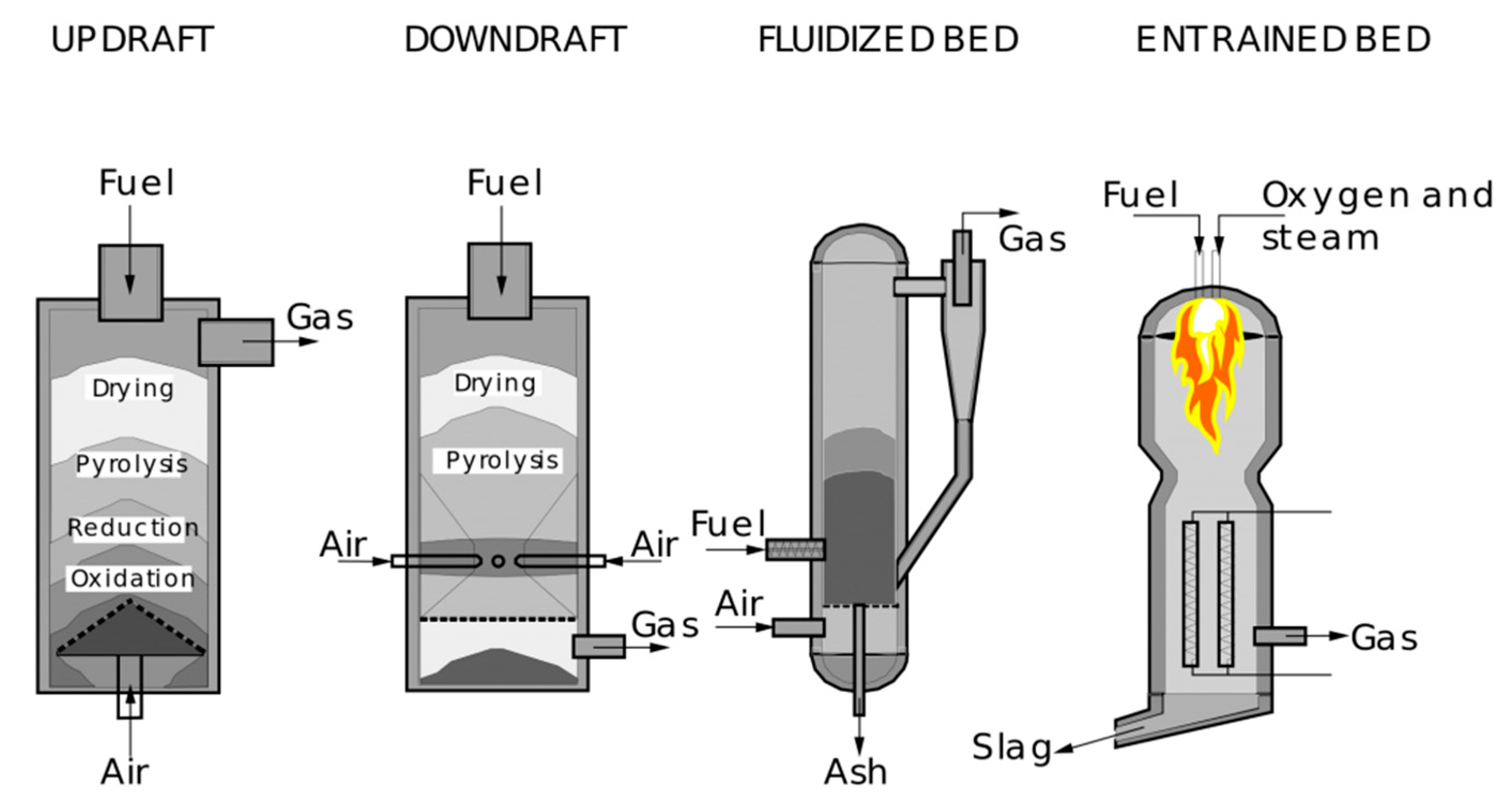
1. Introduction
2. Materials and Methods
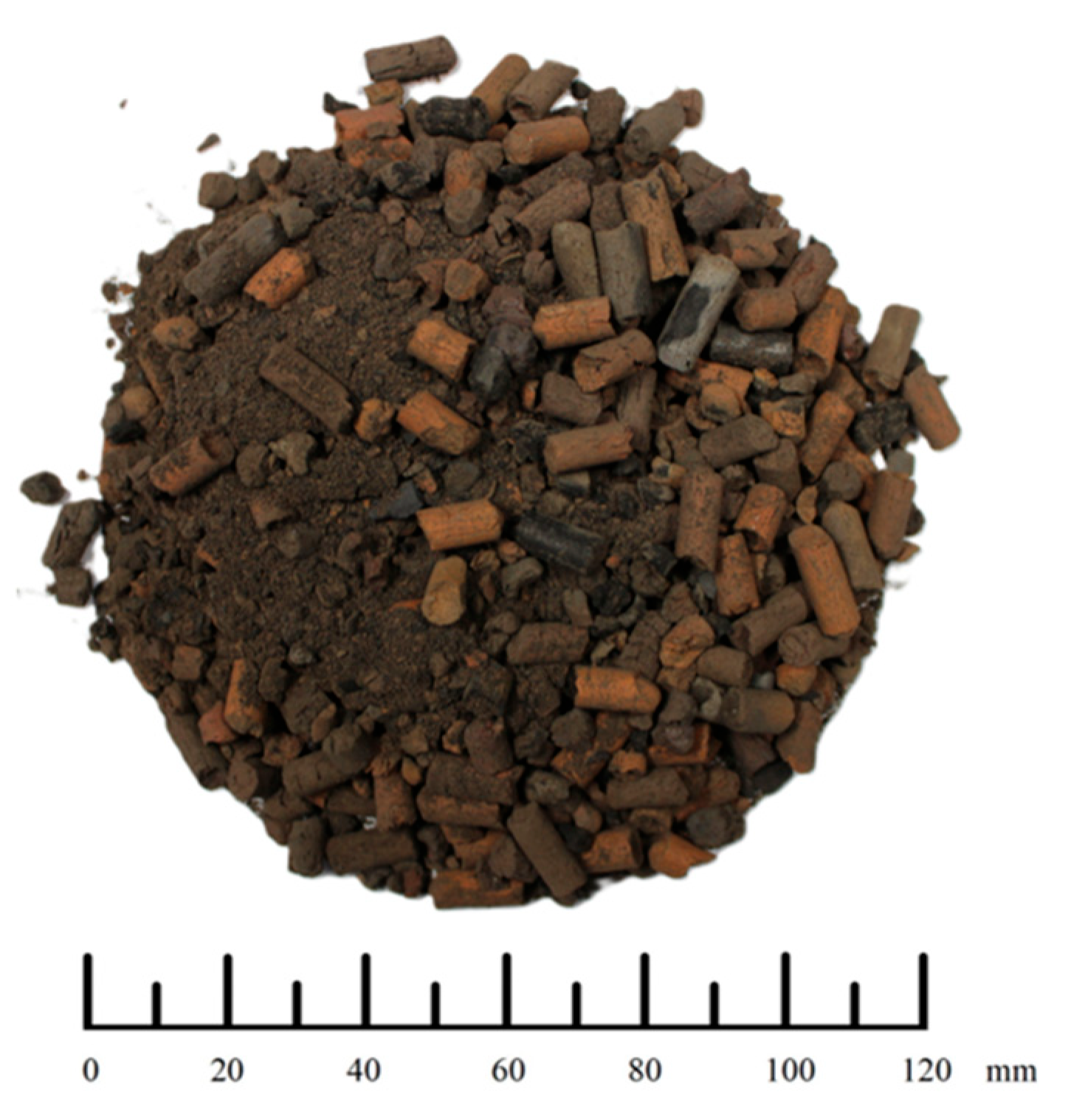
2.1. Feedstock
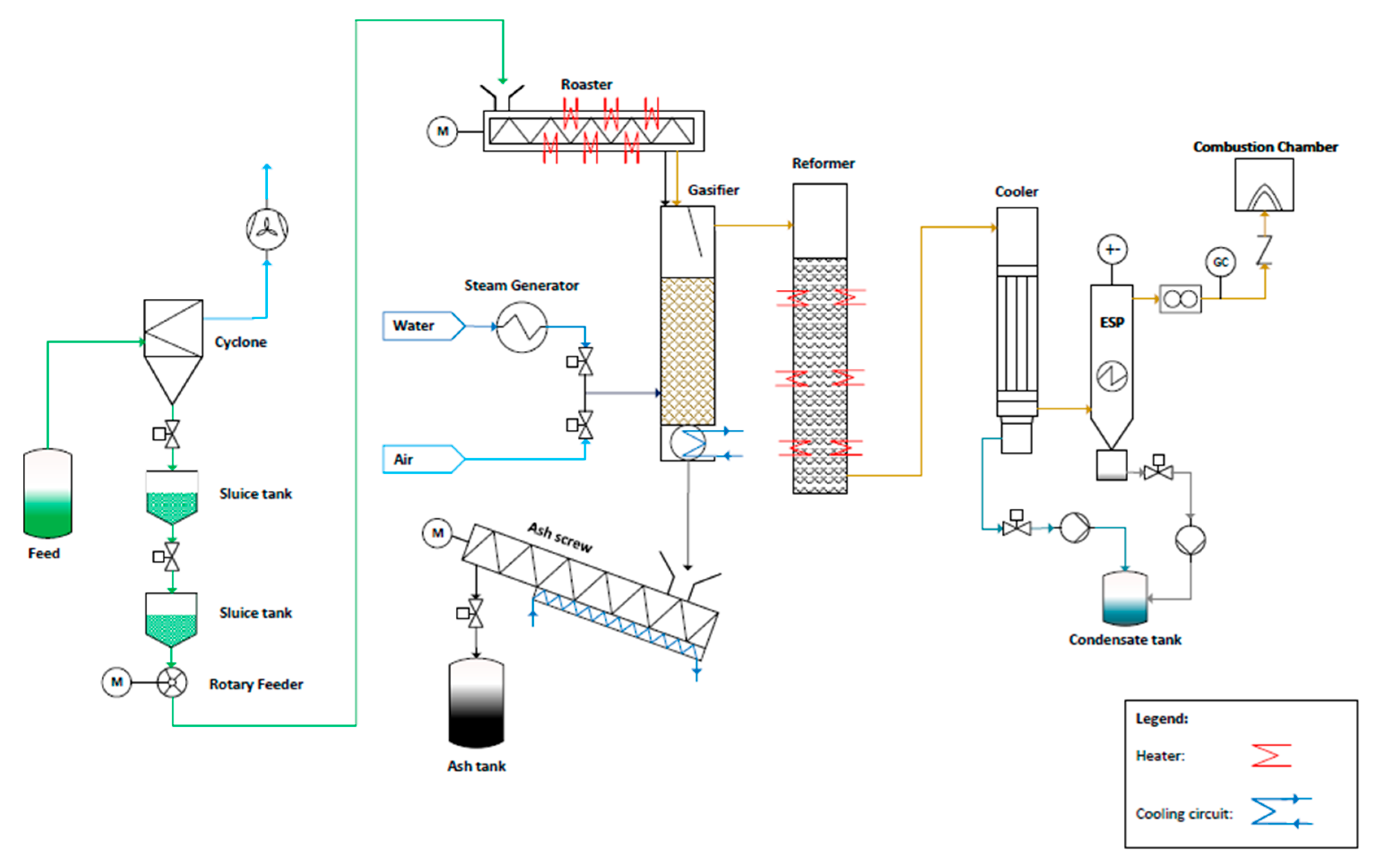
2.2. Experimental Setup
2.3. Analytical Methods and Measurements
3. Results and Discussion
3.1. Feedstock Characterization
3.2. Ash Characterization
3.3. Active Carbon Characterization
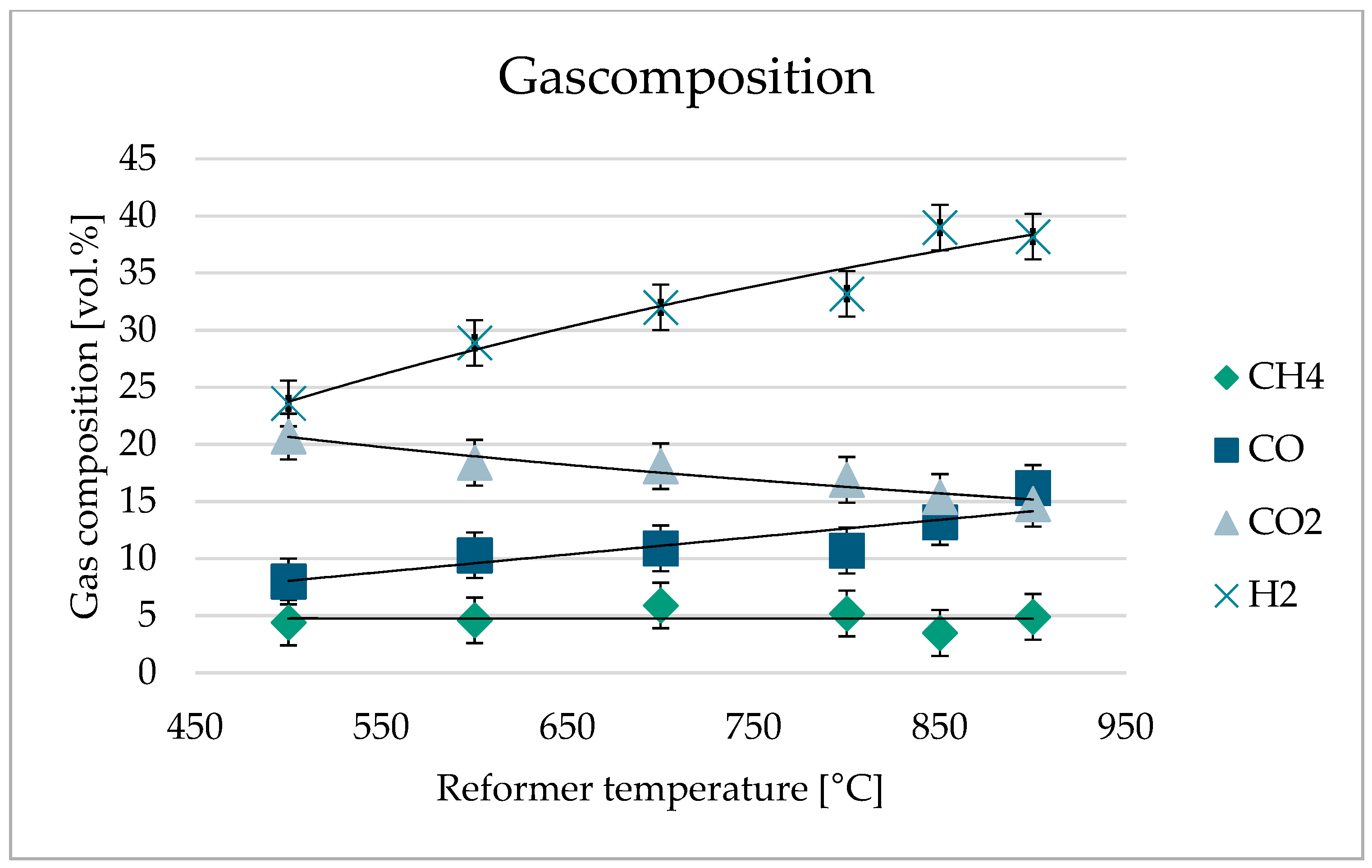
3.4. Product Gas Characterization
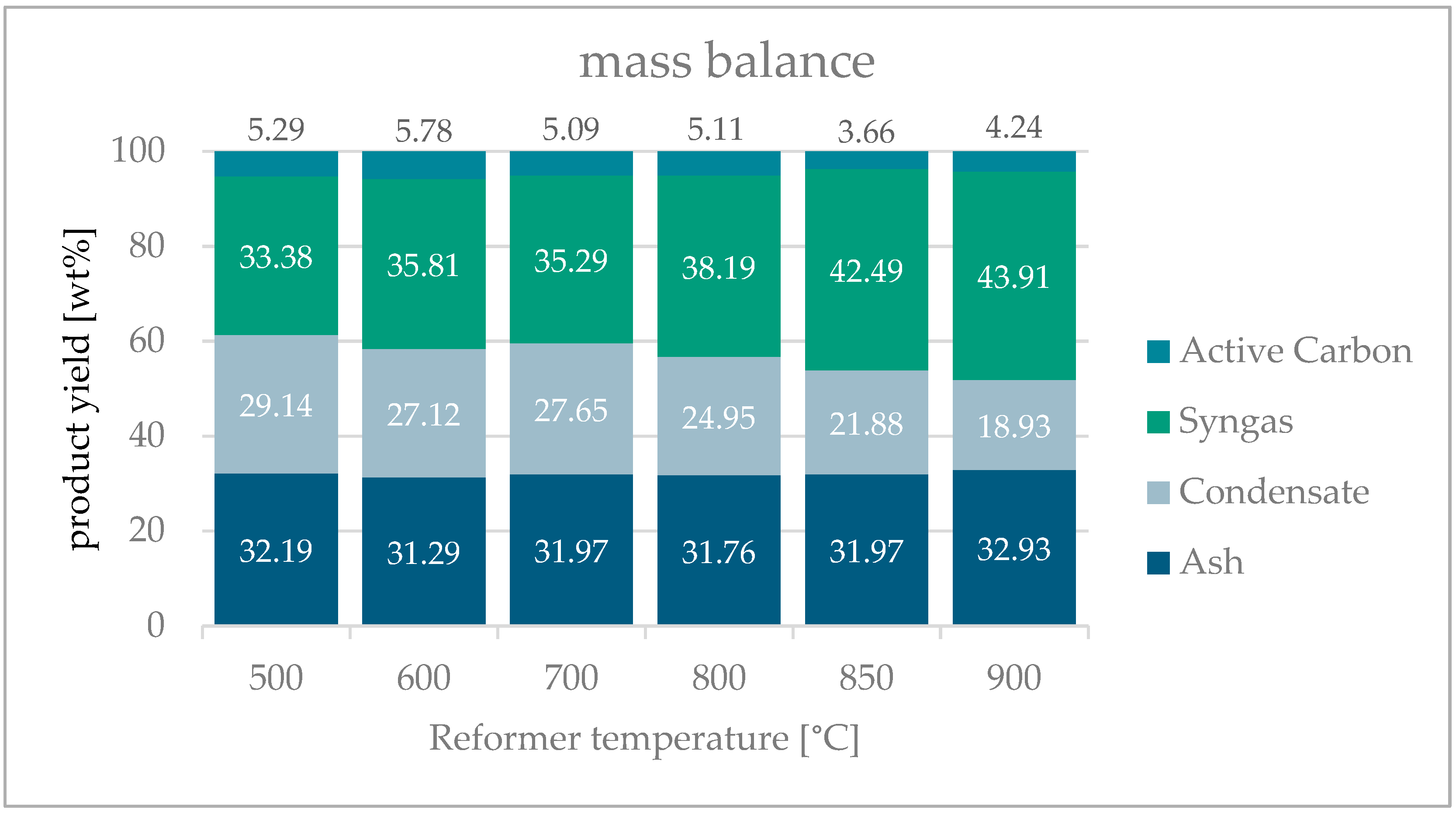
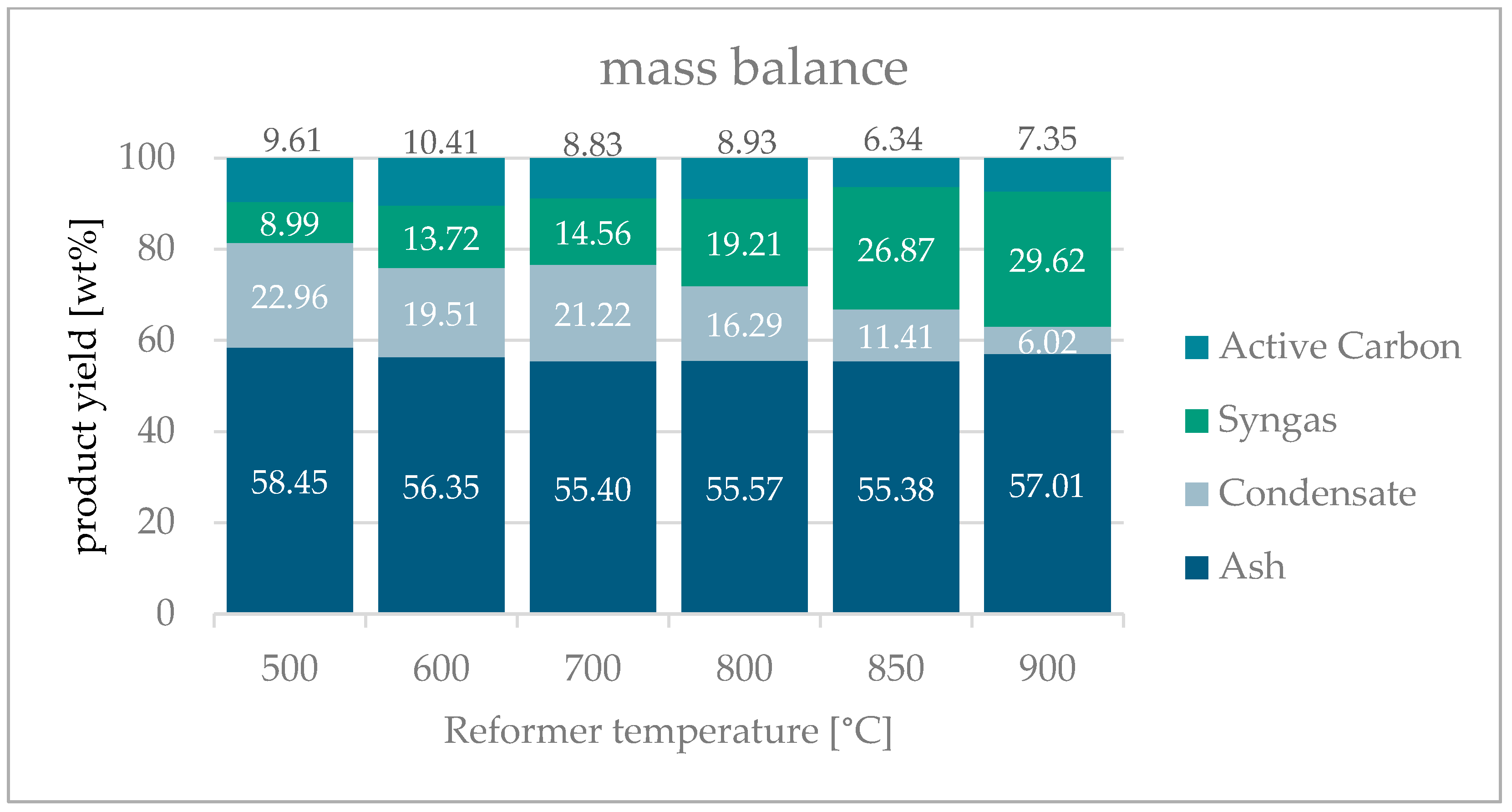
3.5. Mass Balance
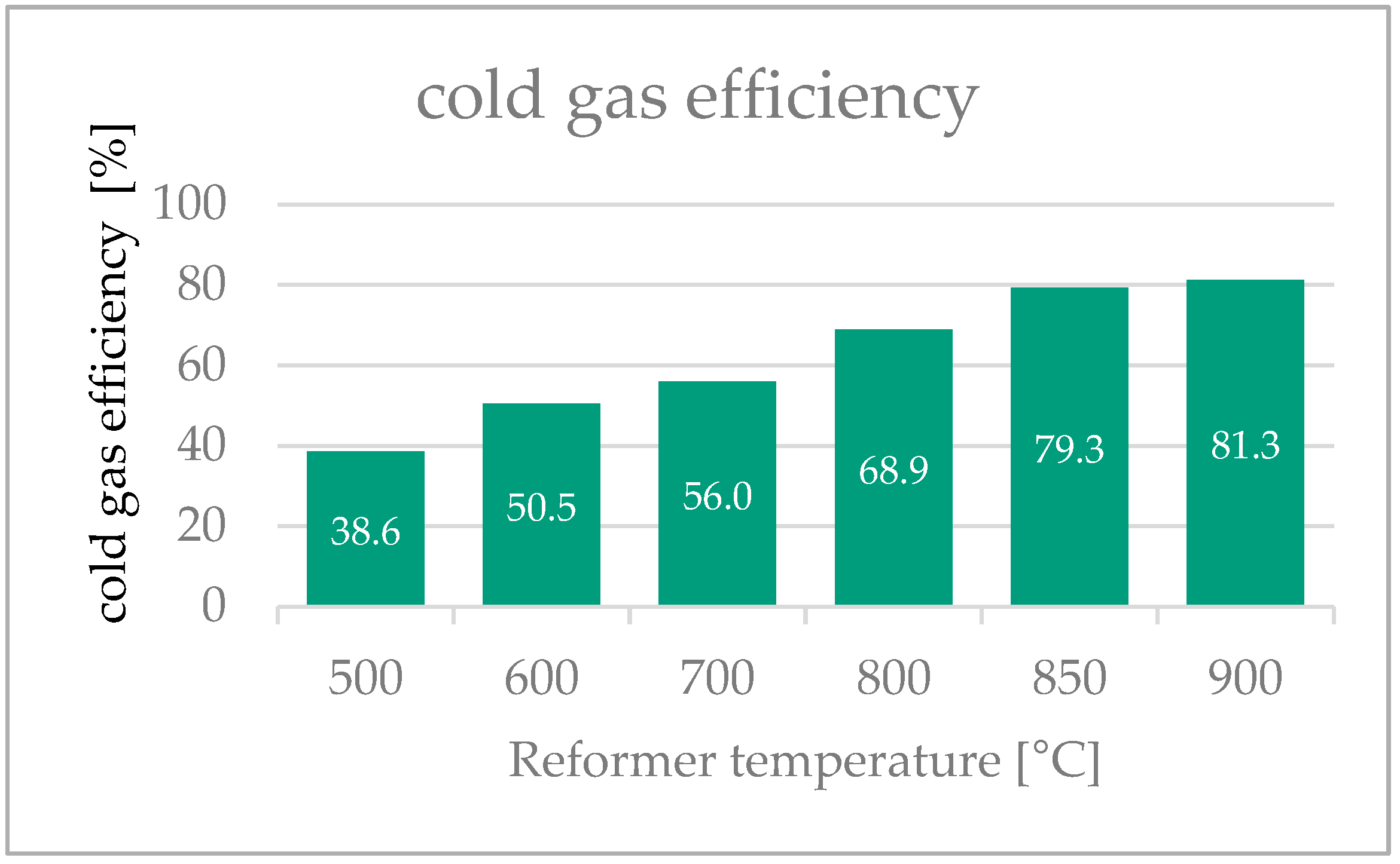
3.6. Cold Gas Efficiency
4. Conclusions
Author Contributions
Funding
Informed Consent Statement
Data Availability Statement
Acknowledgments
Conflicts of Interest
References
- IEA. Global Hydrogen Review 2023. 2023. Available online: https://www.iea.org/reports/global-hydrogen-review-2023 (accessed on 7 February 2025).
- Bundesministerium für Wirtschaft und Energie (BMWi), Nationales Reformprogramm 2020—Die Nationale Wasserstoffstrategie 2020. Available online: https://www.bmbf.de/SharedDocs/Downloads/DE/2020/nationale-wasserstoffstragegie-pdf.pdf?__blob=publicationFile&v=4 (accessed on 27 February 2025).
- Marouani, I.; Guesmi, T.; Alshammari, B.M.; Alqunun, K.; Alzamil, A.; Alturki, M.; Abdallah, H.H. Integration of Renewable-Energy-Based Green Hydrogen into the Energy Future. Processes 2023, 11, 2685. [Google Scholar] [CrossRef]
- Destatis—Statistisches Bundesamt. Wasserwirtschaft: Entsorgungswege des Klärschlamms aus der Biologischen Abwasserbehandlung 2023. 2024. Available online: https://www.destatis.de/DE/Themen/Gesellschaft-Umwelt/Umwelt/Wasserwirtschaft/Tabellen/ks-016a-klaerschlamm-verwert-art-2023.html (accessed on 11 February 2025).
- Destatis—Statistisches Bundesamt, Pressemitteilung Nr. 472 vom 12. Dezember 2024. 2024. Available online: https://www.destatis.de/DE/Presse/Pressemitteilungen/2024/12/PD24_472_32214.html (accessed on 11 February 2025).
- Farzad, S.; Mandegari, M.A.; Görgens, J.F. A critical review on biomass gasification, co-gasification, and their environmental assessments. Biofuel Res. J. 2016, 3, 483–495. [Google Scholar] [CrossRef]
- Kaltschmitt, M.; Hofbauer, H.; Lenz, V. Energie aus Biomasse; Springer Fachmedien Wiesbaden: Wiesbaden, Germany, 2024. [Google Scholar]
- Molino, A.; Chianese, S.; Musmarra, D. Biomass gasification technology: The state of the art overview. J. Energy Chem. 2016, 25, 10–25. [Google Scholar] [CrossRef]
- Wang, F.; Peng, W.; Zeng, X.; Sun, D.; Cui, G.; Han, Z.; Wang, C.; Xu, G. Insight into staged gasification of biomass waste: Essential fundamentals and applications. Sci. Total Environ. 2024, 953, 175954. [Google Scholar] [CrossRef]
- Faizan, M.; Song, H. Critical review on catalytic biomass gasification: State-of-Art progress, technical challenges, and perspectives in future development. J. Clean. Prod. 2023, 408, 137224. [Google Scholar] [CrossRef]
- Tezer, Ö.; Karabağ, N.; Öngen, A.; Çolpan, C.Ö.; Ayol, A. Biomass gasification for sustainable energy production: A review. Int. J. Hydrogen Energy 2022, 47, 15419–15433. [Google Scholar] [CrossRef]
- Vergasung und Verbrennung: Was ist der Unterschied? Bioroot Energy, Inc.: Darby, MT, USA; Available online: https://www.biorootenergy.com/alcohol-solutions/gasification-incineration-whats-the-difference/ (accessed on 29 April 2025).
- Ren, J.; Cao, J.-P.; Zhao, X.-Y.; Yang, F.-L.; Wei, X.-Y. Recent advances in syngas production from biomass catalytic gasification: A critical review on reactors, catalysts, catalytic mechanisms and mathematical models. Renew. Sustain. Energy Rev. 2019, 116, 109426. [Google Scholar] [CrossRef]
- Maitlo, G.; Ali, I.; Mangi, K.H.; Ali, S.; Maitlo, H.A.; Unar, I.N.; Pirzada, A.M. Thermochemical Conversion of Biomass for Syngas Production: Current Status and Future Trends. Sustainability 2022, 14, 2596. [Google Scholar] [CrossRef]
- SSharma, K.; Shivapuji, A.M.; Dasappa, S. Characterization of a novel two-stage high ash coal gasifier for low tar and high calorific value gas. Appl. Therm. Eng. 2023, 237, 121775. [Google Scholar] [CrossRef]
- Gao, Y.; Wang, M.; Raheem, A.; Wang, F.; Wei, J.; Xu, D.; Song, X.; Bao, W.; Huang, A.; Zhang, S.; et al. Syngas Production from Biomass Gasification: Influences of Feedstock Properties, Reactor Type, and Reaction Parameters. ACS Omega 2023, 8, 31620–31631. [Google Scholar] [CrossRef]
- Datta, S.; Sarkar, P.; Chavan, P.D.; Saha, S.; Sahu, G.; Sinha, A.K.; Saxena, V. Agglomeration behaviour of high ash Indian coals in fluidized bed gasification pilot plant. Appl. Therm. Eng. 2015, 86, 222–228. [Google Scholar] [CrossRef]
- Krishnamoorthy, V.; Pisupati, S. A Critical Review of Mineral Matter Related Issues during Gasification of Coal in Fixed, Fluidized, and Entrained Flow Gasifiers. Energies 2015, 8, 10430–10463. [Google Scholar] [CrossRef]
- Qi, X.; Song, W.; Song, G. Influence of Ashing Temperature on Predicting Slagging Characteristics of Xinjiang High-Sodium Low-Rank Coal and Strategy of Using Mineral Additives as Potential Slagging Preventatives. ACS Omega 2021, 6, 8850–8861. [Google Scholar] [CrossRef] [PubMed]
- Kosminski, A.; Ross, D.P.; Agnew, J.B. Reactions between sodium and kaolin during gasification of a low-rank coal. Fuel Process. Technol. 2006, 87, 1051–1062. [Google Scholar] [CrossRef]
- Neumann, J.; Binder, S.; Apfelbacher, A.; Gasson, J.R.; García, P.R.; Hornung, A. Production and characterization of a new quality pyrolysis oil, char and syngas from digestate—Introducing the thermo-catalytic reforming process. J. Anal. Appl. Pyrolysis 2015, 113, 137–142. [Google Scholar] [CrossRef]
- Furusawa, Y.; Taguchi, H.; Ismail, S.N.; Thangavel, S.; Matsuoka, K.; Fushimi, C. Estimation of cold gas efficiency and reactor size of low-temperature gasifier for advanced-integrated coal gasification combined cycle systems. Fuel Process. Technol. 2019, 193, 304–316. [Google Scholar] [CrossRef]
- Werle, S.; Dudziak, M. Analysis of Organic and Inorganic Contaminants in Dried Sewage Sludge and By-Products of Dried Sewage Sludge Gasification. Energies 2014, 7, 462–476. [Google Scholar] [CrossRef]
- Schwitalla, D.; Reinmöller, M.; Forman, C.; Wolfersdorf, C.; Gootz, M.; Bai, J.; Guhl, S.; Neuroth, M.; Meyer, B. Ash and slag properties for co-gasification of sewage sludge and coal: An experimentally validated modeling approach. Fuel Process. Technol. 2018, 175, 1–9. [Google Scholar] [CrossRef]
- Schmitt, N.; Apfelbacher, A.; Jäger, N.; Daschner, R.; Stenzel, F.; Hornung, A. Thermo-chemical conversion of biomass and upgrading to biofuel: The Thermo-Catalytic Reforming process—A review. Biofuels Bioprod. Biorefin. 2019, 13, 822–837. [Google Scholar] [CrossRef]
- Syed-Hassan, S.S.A.; Wang, Y.; Hu, S.; Su, S.; Xiang, J. Thermochemical processing of sewage sludge to energy and fuel: Fundamentals, challenges and considerations. Renew. Sustain. Energy Rev. 2017, 80, 888–913. [Google Scholar] [CrossRef]
- Robinson, T.; Bronson, B.; Gogolek, P.; Mehrani, P. Comparison of the air-blown bubbling fluidized bed gasification of wood and wood–PET pellets. Fuel 2016, 178, 263–271. [Google Scholar] [CrossRef]
- Gil-Lalaguna, N.; Sánchez, J.L.; Murillo, M.B.; Gea, G. Use of sewage sludge combustion ash and gasification ash for high-temperature desulphurization of different gas streams. Fuel 2015, 141, 99–108. [Google Scholar] [CrossRef]
- Jäger, N.; Conti, R.; Neumann, J.; Apfelbacher, A.; Daschner, R.; Binder, S.; Hornung, A. Thermo-Catalytic Reforming of Woody Biomass. Energy Fuels 2016, 30, 7923–7929. [Google Scholar] [CrossRef]
- Migliaccio, R.; Brachi, P.; Montagnaro, F.; Papa, S.; Tavano, A.; Montesarchio, P.; Ruoppolo, G.; Urciuolo, M. Sewage Sludge Gasification in a Fluidized Bed: Experimental Investigation and Modeling. Ind. Eng. Chem. Res. 2021, 60, 5034–5047. [Google Scholar] [CrossRef]
- Jüntgen, H. Activated carbon as catalyst support: A review of new research results. Fuel 1986, 65, 1436–1446. [Google Scholar] [CrossRef]
- Corma, A.; Huber, G.; Sauvanaud, L.; Oconnor, P. Processing biomass-derived oxygenates in the oil refinery: Catalytic cracking (FCC) reaction pathways and role of catalyst. J. Catal. 2007, 247, 307–327. [Google Scholar] [CrossRef]
- Amin, A.M.; Croiset, E.; Epling, W. Review of methane catalytic cracking for hydrogen production. Int. J. Hydrogen Energy 2011, 36, 2904–2935. [Google Scholar] [CrossRef]
- Jin, X.; Wang, Q.; Li, X.; Li, T.; Wang, M.; Kong, J.; Yan, L.; Chang, L.; Wang, J.; Bao, W. Coke formation on activated carbon during catalytic upgrading of coal pyrolysis volatiles. J. Fuel Chem. Technol. 2021, 49, 609–616. [Google Scholar] [CrossRef]
- Voorhies, A. Carbon Formation in Catalytic Cracking. Ind. Eng. Chem. 1945, 37, 318–322. [Google Scholar] [CrossRef]
- Hosokai, S.; Kumabe, K.; Ohshita, M.; Norinaga, K.; Li, C.; Hayashi, J. Mechanism of decomposition of aromatics over charcoal and necessary condition for maintaining its activity. Fuel 2008, 87, 2914–2922. [Google Scholar] [CrossRef]
- Yi, H.; Li, F.; Ning, P.; Tang, X.; Peng, J.; Li, Y.; Deng, H. Adsorption separation of CO2, CH4, and N2 on microwave activated carbon. Chem. Eng. J. 2013, 216, 635–642. [Google Scholar] [CrossRef]
- Wang, S.; Nam, H.; Nam, H. Preparation of activated carbon from peanut shell with KOH activation and its application for H2S adsorption in confined space. J. Environ. Chem. Eng. 2020, 8, 103683. [Google Scholar] [CrossRef]
- Wang, S.; Nam, H.; Nam, H. Utilization of cocoa activated carbon for trimethylamine and hydrogen sulfide gas removals in a confined space and its techno-economic analysis and life-cycle analysis. Environ. Prog. Sustain. Energy 2019, 38, e13241. [Google Scholar] [CrossRef]
- Neumann, J.; Hornung, A.; Apfelbacher, A.; Daschner, R. Pyrolysis of residual biomass via thermo-catalytic reforming—Experimental investigation of sewage sludge. In Proceedings of the 25th European Biomass Conference and Exhibition, Stockholm, Sweden, 12–15 June 2017. [Google Scholar]
- Han, L.; Xin, C.; Wu, Y.; Ma, K.; Rong, N.; Qi, Z.; Ding, H.; Xu, G.; Zhao, J.; Yu, H. Enhanced Sewage Sludge Gasification by Bauxite-Modified Carbide Slag for Hydrogen-Rich Syngas Production with In Situ CO2 Capture. Energy Technol. 2023, 11, 2300071. [Google Scholar] [CrossRef]
- Schweitzer, D.; Gredinger, A.; Schmid, M.; Waizmann, G.; Beirow, M.; Spörl, R.; Scheffknecht, G. Steam gasification of wood pellets, sewage sludge and manure: Gasification performance and concentration of impurities. Biomass Bioenergy 2018, 111, 308–319. [Google Scholar] [CrossRef]
- Hornung, A.; Jahangiri, H.; Ouadi, M.; Kick, C.; Deinert, L.; Meyer, B.; Grunwald, J.; Daschner, R.; Apfelbacher, A.; Meiller, M.; et al. Thermo-Catalytic Reforming (TCR)–An important link between waste management and renewable fuels as part of the energy transition. Appl. Energy Combust. Sci. 2022, 12, 100088. [Google Scholar] [CrossRef]
- Mathieu, P.; Dubuisson, R. Performance analysis of a biomass gasifier. Energy Convers. Manag. 2002, 43, 1291–1299. [Google Scholar] [CrossRef]
- Ighalo, J.O.; Amama, P.B. Recent advances in the catalysis of steam reforming of methane (SRM). Int. J. Hydrogen Energy 2024, 51, 688–700. [Google Scholar] [CrossRef]
- Zhang, H.; Sun, Z.; Hu, Y.H. Steam reforming of methane: Current states of catalyst design and process upgrading. Renew. Sustain. Energy Rev. 2021, 149, 111330. [Google Scholar] [CrossRef]
- de Andrés, J.M.; Narros, A.; Rodríguez, M.E. Air-steam gasification of sewage sludge in a bubbling bed reactor: Effect of alumina as a primary catalyst. Fuel Process. Technol. 2011, 92, 433–440. [Google Scholar] [CrossRef]
- Fazil, A.; Kumar, S.; Mahajani, S.M. Gasification and Co-gasification of paper-rich, high-ash refuse-derived fuel in downdraft gasifier. Energy 2023, 263, 125659. [Google Scholar] [CrossRef]
- Puig-Arnavat, M.; Bruno, J.C.; Coronas, A. Review and analysis of biomass gasification models. Renew. Sustain. Energy Rev. 2010, 14, 2841–2851. [Google Scholar] [CrossRef]
- Choi, Y.-K.; Cho, M.-H.; Kim, J.-S. Steam/oxygen gasification of dried sewage sludge in a two-stage gasifier: Effects of the steam to fuel ratio and ash of the activated carbon on the production of hydrogen and tar removal. Energy 2015, 91, 160–167. [Google Scholar] [CrossRef]
- Seo, H.-K.; Park, S.; Lee, J.; Kim, M.; Chung, S.-W.; Chung, J.-H.; Kim, K. Effects of operating factors in the coal gasification reaction. Korean J. Chem. Eng. 2011, 28, 1851–1858. [Google Scholar] [CrossRef]
- Brachi, P.; Di Fraia, S.; Massarotti, N.; Vanoli, L. Combined heat and power production based on sewage sludge gasification: An energy-efficient solution for wastewater treatment plants. Energy Convers. Manag. X 2022, 13, 100171. [Google Scholar] [CrossRef]
- Dogru, M.; Midilli, A.; Howarth, C.R. Gasification of sewage sludge using a throated downdraft gasifier and uncertainty analysis. Fuel Process. Technol. 2001, 75, 55–82. [Google Scholar] [CrossRef]
- Kang, S.-W.; Dong, J.-I.; Kim, J.-M.; Lee, W.-C.; Hwang, W.-G. Gasification and its emission characteristics for dried sewage sludge utilizing a fluidized bed gasifier. J. Mater. Cycles Waste Manag. 2011, 13, 180–185. [Google Scholar] [CrossRef]


| Parameter | Unit | Sewage Sludge | |||||
|---|---|---|---|---|---|---|---|
| Batch No. | 2 | 2 | 2 | 1 | 1 | 3 | |
| Duration | h | 4 | 4 | 4 | 4 | 4 | 4 |
| Roaster temperature | °C | 450 | 450 | 450 | 450 | 450 | 450 |
| Gasifier temperature | °C | 850 | 850 | 850 | 850 | 850 | 850 |
| Reformer temperature | °C | 500 | 600 | 700 | 800 | 850 | 900 |
| Equivalence Ratio (ER) | 0.13 | 0.13 | 0.12 | 0.13 | 0.13 | 0.12 | |
| Feedstock throughput | kg/h | 10.18 | 10.35 | 11.28 | 11 | 11.25 | 11.27 |
| Air supply | m3/h | 3.77 | 3.79 | 3.77 | 3.76 | 3.76 | 3.74 |
| Steam supply | m3/h | 4.99 | 4.98 | 4.94 | 4.94 | 4.89 | 4.94 |
| Nitrogen supply | m3/h | 0.3 | 0.3 | 0.3 | 0.3 | 0.3 | 0.3 |
| Parameter | Unit | |||
|---|---|---|---|---|
| Feedstock | Sewage sludge | |||
| Batch No. | 1 | 2 | 3 | |
| Total water content | wt% | 8.3 | 11.5 | 8.5 |
| C | wt% | 25.2 | 28.4 | 26.6 |
| H | wt% | 3.7 | 4.3 | 4.2 |
| N | wt% | 3.6 | 3.95 | 3.3 |
| S | wt% | 0.804 | 1.03 | 0.799 |
| O * | wt% | 14.8 | 16.1 | 16.2 |
| Ash content (550 °C) | wt% | 51.9 | 46.1 | 48.9 |
| Higher Heating Value (HHV) | MJ/kg | 11.0 | 12.2 | 11.9 |
| Lower Heating Value (LHV) | MJ/kg | 10.20 | 11.30 | 11.00 |
| Volatile components | wt% | 43.9 | 49.3 | 46.8 |
| Fixed carbon | wt% | 4.2 | 4.6 | 4.3 |
| Parameter | Unit | Trials | |||||
|---|---|---|---|---|---|---|---|
| Reformer temperature | °C | 500 | 600 | 700 | 800 | 850 | 900 |
| Total water content | wt% | 1.4 | 0.7 | 0.7 | 0.7 | 0.4 | 0.3 |
| C | wt% | 6.8 | 6.9 | 4.4 | 3.2 | 4.5 | 7.6 |
| H | wt% | 0.3 | 0.2 | 0.4 | 0.2 | 0.2 | 0.3 |
| N | wt% | 0.61 | 0.2 | 0.13 | 0.23 | 0.24 | 0.36 |
| S | wt% | 0.46 | 0.27 | 0.03 | 0.16 | 0.16 | 0.35 |
| O * | wt% | 2.9 | −0.3 | 0.4 | 0.1 | −0.3 | 0.1 |
| Volatile components | wt% | 6.4 | 3.1 | 2.9 | 2.9 | 2.6 | 4.0 |
| Fixed carbon | wt% | 4.5 | 4.2 | 2.4 | 1.0 | 2.3 | 4.6 |
| Ash content (815 °C) | wt% | 89.0 | 92.7 | 94.7 | 96.1 | 95.1 | 91.3 |
| Higher Heating Value (HHV) | MJ/kg | 2.62 | 2.47 | 1.84 | 1.35 | 1.75 | 2.51 |
| Lower Heating Value (LHV) | MJ/kg | 2.55 | 2.42 | 1.75 | 1.31 | 1.7 | 2.45 |
| Parameter | Unit | Before Trial | Trials | |||||
|---|---|---|---|---|---|---|---|---|
| Reformer temperature | °C | 500 | 600 | 700 | 800 | 850 | 900 | |
| Total water content | wt% | 8.24 | 0.30 | 0.33 | 0.22 | 0.11 | 0.32 | 0.13 |
| C | wt% | 90.42 | 88.07 | 88.98 | 90.59 | 90.72 | 89.37 | 91.10 |
| H | wt% | 0.45 | 0.59 | 0.59 | 0.54 | 0.59 | 0.51 | 0.33 |
| N | wt% | 0.42 | 0.76 | 1.51 | 1.47 | 1.06 | 1.24 | 0.90 |
| S | wt% | 0.23 | 0.25 | 0.63 | 0.52 | 0.34 | 0.68 | 0.92 |
| O * | wt% | 2.10 | 2.63 | 1.29 | 0.57 | −1.61 | 0.48 | −0.67 |
| Ash content (815 °C) | wt% | 6.38 | 7.70 | 7.00 | 6.32 | 8.91 | 7.72 | 7.42 |
| Higher Heating Value (HHV) | MJ/kg | 28.59 | 27.50 | 28.41 | 28.51 | 27.52 | 27.74 | 27.81 |
| Lower Heating Value (LHV) | MJ/kg | 28.31 | 27.57 | 28.29 | 28.40 | 27.39 | 27.63 | 27.74 |
| Parameter | Unit | Trials | |||||
|---|---|---|---|---|---|---|---|
| Reformer temperature | °C | 500 | 600 | 700 | 800 | 850 | 900 |
| Methane (CH4) | vol.% | 4.4 | 4.6 | 5.9 | 5.2 | 3.5 | 4.9 |
| Carbon monoxide (CO) | vol.% | 8.0 | 10.3 | 10.9 | 10.7 | 13.2 | 16.2 |
| Carbon dioxide (CO2) | vol.% | 20.7 | 18.4 | 18.1 | 16.9 | 15.4 | 14.8 |
| Nitrogen (N2) | vol.% | 38.3 | 33.1 | 31.8 | 32.8 | 28.4 | 22.2 |
| Hydrogen (H2) | vol.% | 23.6 | 28.9 | 32.0 | 33.2 | 39 | 38.2 |
| Hydrogen sulfide (H2S) | vol.% | 0.91 | 0.68 | 0.49 | 0.51 | 0.34 | 0.40 |
| Rest (CxHy) | vol.% | 4.09 | 4.02 | 0.81 | 0.69 | 0.16 | 3.3 |
| Gas production | m3/h | 7.41 | 8.34 | 8.79 | 10.23 | 11.27 | 11.39 |
| Gas yield | m3/kgFeed | 0.73 | 0.81 | 0.78 | 0.93 | 1.00 | 1.01 |
| Hydrogen production | gH2/h | 159.8 | 220.2 | 257.0 | 310.4 | 401.3 | 397.4 |
| Hydrogen yield | gH2/kgFeed | 15.7 | 21.3 | 22.8 | 28.2 | 35.7 | 35.3 |
| Lower Heating Value (LHV) | MJ/m3 | 5.13 | 6.07 | 6.95 | 6.80 | 7.27 | 7.92 |
Disclaimer/Publisher’s Note: The statements, opinions and data contained in all publications are solely those of the individual author(s) and contributor(s) and not of MDPI and/or the editor(s). MDPI and/or the editor(s) disclaim responsibility for any injury to people or property resulting from any ideas, methods, instructions or products referred to in the content. |
© 2025 by the authors. Licensee MDPI, Basel, Switzerland. This article is an open access article distributed under the terms and conditions of the Creative Commons Attribution (CC BY) license (https://creativecommons.org/licenses/by/4.0/).
Share and Cite
Gebhard, W.; Zant, S.; Neidel, J.; Apfelbacher, A.; Daschner, R. Conversion of Sewage Sludge with Combined Pyrolysis and Gasification via the Enhanced Carbon-To-X-Output Technology. Biomass 2025, 5, 28. https://doi.org/10.3390/biomass5020028
Gebhard W, Zant S, Neidel J, Apfelbacher A, Daschner R. Conversion of Sewage Sludge with Combined Pyrolysis and Gasification via the Enhanced Carbon-To-X-Output Technology. Biomass. 2025; 5(2):28. https://doi.org/10.3390/biomass5020028
Chicago/Turabian StyleGebhard, Wolfgang, Sebastian Zant, Johannes Neidel, Andreas Apfelbacher, and Robert Daschner. 2025. "Conversion of Sewage Sludge with Combined Pyrolysis and Gasification via the Enhanced Carbon-To-X-Output Technology" Biomass 5, no. 2: 28. https://doi.org/10.3390/biomass5020028
APA StyleGebhard, W., Zant, S., Neidel, J., Apfelbacher, A., & Daschner, R. (2025). Conversion of Sewage Sludge with Combined Pyrolysis and Gasification via the Enhanced Carbon-To-X-Output Technology. Biomass, 5(2), 28. https://doi.org/10.3390/biomass5020028