Abstract
Orbital angular momentum (OAM) beams exhibit divergence during transmission, which constrains the capacity of communication system channels. To address these challenges, intelligent reflecting surfaces (IRSs), which can independently manipulate incident electromagnetic waves by adjustment of their amplitude and phase, are employed to construct IRS-assisted OAM communication systems. By introducing additional information pathways, IRSs enhance diversity gain. We studied the simulations of two placement methods for an IRS: arbitrary placement and standard placement. In the case of arbitrary placement, the beam reflected by the IRS can be decomposed into different OAM modes, producing various reception powers corresponding to each OAM mode component. This improves the signal-to-noise ratio (SNR) at the receiver, thereby enhancing channel capacity. In particular, when the IRS is symmetrically and uniformly positioned at the center of the main transmission axis, its elements can be approximated as a uniform circular array (UCA). This configuration not only achieves optimal reception along the direction of the maximum gain of the orbital angular momentum beam but also reduces the antenna radius required at the receiver to half or even less.
1. Introduction
Recently, the intelligent reflecting surface (IRS) has become one of the candidate technologies in sixth-generation (6G) communications [1,2,3,4,5]. An IRS is modeled as an array of passive reflecting elements, each capable of independently applying a phase shift to incident electromagnetic (EM) waves to facilitate various communication objectives [6,7,8,9]. In general, IRSs can be categorized into active and passive types based on their power consumption. For traditional communication systems, IRSs not only build an effective information transmission path when the transmitter and receiver are blocked but also transmits energy to enhance the transmission effect of the multiple-input multiple-output (MIMO) system [10,11,12,13]. The channel model of an IRS-assisted communication mechanism incorporates the signal path introduced by the IRS-reflected beam, thereby increasing the system’s degrees of freedom [14,15,16]. In this mechanism, the direct path and the reflection path both carry the same information; they can be superimposed at the terminal to improve signal quality [17]. In addition, IRSs can assist communication systems in channel estimation and secure communication tasks [18]. The flexible deployment allows IRSs to seamlessly integrate existing infrastructure into the communication network, enhancing system adaptability and efficiency [19].
Orbital angular momentum (OAM) can also be regarded as a potential key technology [20,21,22,23]. Generally, OAM can be generated by UCA antennas, which is expected to be implemented for large-capacity communications [24,25,26,27,28]. However, the phase plane coaxial receiving the OAM transmission has a high capacity but requires strict alignment and a large receiving antenna size [29,30]. Due to beam divergence, the distance is a critical issue before OAM can be applied, which is a challenging problem [31,32,33]. Hence, the general circular array has been proposed to cover large phase planes physically with self-alignment and no restriction on the antenna distribution within the array [34,35,36,37,38,39]. In addition, a dedicated parabolic antenna can be used to converge the OAM beam to further increase the transmission distance [40,41,42]. While OAM theoretically offers a promising prospect for opening up new dimensional spectrum resources and achieving high-spectral-efficiency communication, current OAM-based communication systems still face a series of severe and structured challenges when moving from laboratory research to practical deployment. First, the divergence of OAM leads to severe attenuation. OAM beams are divergent and take an inverted conical form, which causes their energy to spread rapidly with transmission distance, resulting in significant path loss and severely limiting long-distance transmission [43,44,45,46,47,48,49,50,51,52]. Second, OAM systems have extremely high requirements for antenna fabrication and transmitter–receiver alignment. Minor deviations in antenna fabrication or alignment can cause inter-mode crosstalk, leading to a sharp decline in multiplexing performance: this poses an obstacle to terminal mobility scenarios [53,54,55,56,57,58,59]. Third, the limited number of modes and aperture constraints constitute major bottlenecks. The number of orthogonal modes available for multiplexing is directly limited by the aperture size of the transmitter. It is difficult to implement multi-mode multiplexing in practical devices with size restrictions (such as smartphones), which limits the potential for improving channel capacity [55,59,60,61]. Finally, many existing OAM demonstration systems rely on large, high-cost, and inflexible phased arrays or spiral phase plates (SPPs) to generate beams. This greatly increases system complexity and cost, making it difficult to meet the core requirements of future wireless networks of low power consumption, low cost, and reconfigurability [62]. The emergence of IRSs, however, provides a highly promising solution to address many of the aforementioned challenges simultaneously.
Because IRSs could enhance traditional communication systems, an IRS-assisted OAM transmission mechanism could be constructed to overcome the divergence problem in OAM-based communications. IRS has been utilized to provide additional access for OAM wireless links when the line-of-sight (LoS) path is blocked [63]. In this paper, an IRS-assisted OAM communication system in the presence of a LoS path is studied, and the mathematical model is established. Furthermore, IRS-assisted OAM transmission is evaluated in detail. In addition to enhancing physical-layer performance through IRS-aided OAM transmission system, system performance can be further improved by extracting modulation features using advanced signal processing methods such as multi-modal feature networks [64]. When OAM is deployed in LoS point-to-point transmission scenarios, it exhibits a divergent inverted conical beam form. Thus, with the transmission distance and transmission power kept constant, the size of the receiving antenna is increased. The research objective in this paper is to verify the performance gain of an IRS when assisting OAM in information transmission, demonstrate the effective convergence performance of IRSs for OAM, and show that IRS can reduce the receiving antenna size. The major contribution of this paper is the construction of an IRS-aided OAM transmission system. Furthermore, focusing on the performance gains of the system, the following two parts were carried out:
- The performance gains of an OAM transmission system are analyzed under two scenarios: random placement and uniform placement of the IRS.
- The convergence performance of an IRS with OAM is verified through simulations. Further, it is demonstrated that the IRS can achieve performance gains in improving the channel capacity of the OAM transmission system and reducing the receiver size.
2. System Architecture
A large-capacity point-to-point data transmission link is established by multiplexing the OAM wave between the macro base station (BS) and the self-backhaul small-cell (SBSC) station, and the IRS is used to assist with transmission. The system structure is shown in Figure 1. The BS sets up a large-scale phased array antenna and radiates the OAM beam with mode l by adjusting the phase of the vibrator in the phased array antenna, and then the information is transmitted to the SBSC station via the IRSs and direct path. A single IRS consists of small reflective elements spaced apart and distributed on the transmission path. In this case, the transmission path introduced by the IRS appears between the BS and the SBSC station. When the IRS assists the OAM communication system, a single IRS or multiple IRSs can be used. The SBSC station at the receiving end uses the UCA with a radius of . The received signal is digitally processed and restored and then transmitted to the user end.
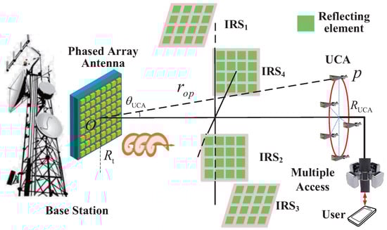
Figure 1.
The OAM communication system assisted by an IRS.
As shown in Figure 1, the macro BS is connected with IRSs by wireless methods. Furthermore, after the OAM waves reach the IRS array, one of the IRSs in the array adjusts the amplitude and phase of the waves to reflect them toward the UE. Similarly, the beams can be reflected by the IRSs,. Note that the scheme of the macro BS antenna is not the UCA structure; the phased-array antenna generates multiple shaped beams pointing to the SBSC station. As a special case, when multiple IRSs are distributed symmetrically in the center of the main OAM transmission axis, the IRS array can be directly equivalent to a coaxial multi-ring UCA with a large radius. Therefore, the beam radiated by the IRS-equivalent UCA and the beam generated by the BS phased-array antenna can be directly added.
2.1. Channel Model with IRS
After all the OAM waves are reflected by the IRS, the signal received by the SBSC station can be expressed as
where is the complex signal on the UCA transmitter antenna , and is the channel response from the BS to the i-th IRS. is the phase shift matrix of the i-th IRS, and . represents the phase-shift values of the corresponding elements in the i-th IRS. is the channel from the i-th IRS to the SBSC, is the channel response from the i-th element of the transmission antenna to the SBSC, and is a Gaussian white noise vector with dimensions . The total signal received by the UCA at the receiving end can be divided into two parts. One is the OAM beam signal reflected by the IRS, and the other is the OAM signal directly received under the LoS channel. When the IRS is arbitrarily distributed, the former can be understood as a traditional MIMO signal. The sum of the signals is the superposition of the traditional MIMO signal and the OAM signal. The OAM channel characteristics assisted by IRS are analyzed. Simultaneously left-multiply both sides of Equation (1) by the matrix .
where represents a block diagonal matrix, and denotes the Hermitian transpose. represents the diagonal matrix obtained after singular value decomposition (SVD) of the line-of-sight channel between BS and UE, which indicates the gain between modes under the LoS channel. denotes the Fourier transform matrix. According to the channel characteristics of OAM, the LoS path in the channel formula is directly changed to a diagonal matrix, and the channel formula for transmitting information according to OAM is obtained. The channel state information (CSI) of the entire communication system for IRS-assisted OAM transmission can be estimated [65]. When all CSI at the originating end is known, it can be seen from Equation (2) that the assistant channel created by the introduction of the IRS is added in the OAM information transmission process, which means that the degrees of freedom of the entire OAM communication system become higher. The configuration of the IRS can increase the channel capacity of the transmission system. At the same time, because of the introduction of the IRS, the received signal strength and signal-to-noise ratio (SNR) at the receiving end increase.
For the channel estimation method of passive IRS, the cascaded channel decomposition method can be adopted, which constructs linear equations through IRS phase switching to solve the Khatri–Rao product. First, without deploying the IRS, the direct LoS channel between the BS and UE is estimated. Subsequently, by switching the IRS phases, the phase-shift values of each element in the IRS (within the set ) are configured. Finally, based on the mathematical properties of the Khatri–Rao product, submatrices are extracted; further SVD is then performed to separate the channel vectors, and channels and are ultimately obtained.
2.2. Capacity Optimization of OAM System with IRS
According to information theory, the sum capacity of the OAM system with IRSs in Equation (2) is given by the mutual information rate . Therefore, configuring the phase shift matrix of the IRS to achieve optimal beamforming and maximize the channel capacity of the IRS-assisted OAM communication system is the first problem to be solved. After that, recovering the received signal according to the downlink signal is the problem after data transmission. The channel capacity of the entire IRS-assisted OAM transmission system can be expressed as
where is the total transmission power, N denotes the number of OAM modes, B denotes the bandwidth, and is the variance of the noise. represents the superposition of the reflected path and the direct path through IRS, and it can be regarded as the total channel from the base station to the user after the deployment of IRS. Equation (6) is the channel capacity formula for the IRS-assisted OAM communication system.
When the CSI of the IRS-assisted OAM system is known, the final optimization problem can be expressed as
Equation (8) is the formulation of the optimization problem, which has the goal of maximizing the channel capacity of the IRS-assisted OAM transmission system. The optimization problem in Equation (8) aims to optimize to maximize the value of the component in the desired OAM mode during transmission. Then the maximum diversity power is obtained, and the capacity reaches its maximum value. The optimization problem in Equation (8) can be transformed into a quadratically constrained quadratic program (QCQP) and can be solved by the majorization–minimization (MM) algorithm proposed in [66]. Then the solution of can be obtained, which makes the IRS achieve better beamforming. The basic mathematical principles of solving the QCQP using the MM algorithm are further introduced as follows: The optimization problem to be solved is
First, the following surrogate function is constructed:
where L denotes the Lipschitz constant. This function satisfies , and . Furthermore, subproblem solving minimization step) is conducted.
Monotonicity is guaranteed by the properties of the surrogate function. When the objective function is a semi-algebraic function, the MM algorithm converges to a critical point (specifically a Clarke critical point). When the objective function is strongly convex, the algorithm achieves locally linear convergence. Given that OAM point-to-point transmission relies on a static LoS channel, an offline solution approach is adopted to realize the adjustment of the IRS. The overall computational complexity can be decomposed according to the calculation steps:
- The computational load of the gradient calculation part is ;
- The computational load of the surrogate function update part is ;
- The total complexity per iteration is .
2.3. Special Case of IRS-Aided OAM System
When each IRS is symmetrically distributed on the transmission path with the z-axis as the center, the elements in the a-th row and the b-th column in the i-th IRS and the elements on the other IRSs are co-circular to form the v-th-equivalent UCA. The phase distribution in space meets the conditions for generating OAM beams. At this time, after reasonable adjustment by the IRS, the beams reaching the user end through the IRS are also OAM beams, which becomes a special case of OAM beam transmission. In order to make the OAM beam received by the SBSC in the LoS superimpose with the signal through the IRS, all elements in the same circle have the same amplitude and compensate for phase differences on the path through the IRS and in the direct path. At this time, and in Equation (2) are both cyclic symmetric Fourier matrices, i.e.,
is the received OAM signal from the BS to the receiving end user, i.e.,
For the transmitter, when using UCA to generate an OAM beam, the OAM beam can be expressed as [67]
where is the radius of the phased-array antenna when it is equivalent to UCA to generate OAM waves. n denotes the n-th channel of OAM modes; denotes the OAM mode number; is a spiral phase factor related to the azimuth angle , which determines the periodic variation in the OAM spiral phase plane; denotes the -order Bessel function; is the divergence angle of the OAM beam; is the signal propagation factor for each OAM channel; N is the number of elements of the antenna; d denotes the wave path; i is the imaginary unit; is the amplitude of each OAM signal. Assuming that the distance from point to the BS is , the distance from point to the SBSC is , and the angle between the BS to the element in the a-th row and the b-th column of the i-th IRS and the z-axis is . The phase term of the element in the a-th row and b-th column of the i-th IRS is , the vertical distance between the IRS and the z-axis is , and the spacing between the elements of the IRS is .
The distance from the BS to the element in the a-th row and the b-th column of the i-th IRS is
where , and .
The electric field intensity of the element in the a-th row and the b-th column of the i-th IRS receiving the OAM beam emitted by the BS can be expressed as
The electric field strength of the OAM beam generated by the v-th-equivalent UCA in the IRS reaching the p-th antenna at the SBSC can be expressed as
where is the radius of the equivalent UCA. The total electric field strength received by the p-th antenna is
The complexity of the digital demodulation of the receiver remains unchanged, and the strength of the signal received by the receiver increases. This section considers two scenarios: the random placement of the IRS and its uniform placement along the transmission path. During the analytical modeling process, the LoS channel between the BS and the UE as well as the auxiliary channel added by the introduction of the IRS are considered collectively. Under the scenario of random IRS placement, the phase shifts of the IRS are optimized by solving an optimization problem to maximize the channel capacity.
3. Simulation and Analysis
3.1. Simulation with Random IRS Placement
To demonstrate the advantages of an IRS-assisted OAM communication system over a traditional OAM system without IRSs in terms of channel capacity improvement, simulations were conducted for the passive case. Specifically, the channel capacity were analyzed for scenarios with and without IRSs when the receiver employed a UCA with varying radii. The specific parameters of the OAM transmission simulation with randomly placed IRSs are as follows: The working frequency is 10 GHz. The distance between the BS and the SBSC is 50 m, the number of IRSs is 30, the number of elements on each IRS is 16, and the vertical distance between the IRS and the transmission main axis is 1 m. The phased-array antenna at the transmitter, which follows the form of the UCA with a radius of m, feeds the phase on the elements and generates OAM. Assuming that the IRS is randomly distributed on the transmission path, four OAM modes are multiplexed to transmit information. The radius of the UCA at the receiving end is selected as m, m, and m. The element spacing of the IRS is , where denotes the wavelength. The specific number of elements of UCA in the simulation is 8.
The simulation results are shown in Figure 2. Curves illustrating the variation in channel capacity with SNR—both with and without IRS assistance—under different receiving radii are presented. From 0.2 m to 0.6 m, the channel capacity increases gradually as the differences between the channel eigenvalues become progressively smaller. The SNR refers to the normalized SNR at the receiver (with receiver power normalized). When the receiving radius is the same, compared with the traditional OAM system, the OAM system constructed with IRSs have higher channel capacity by about 1 bit/s/Hz when the SNR at the SBSC is about 20 dB. The reason for the small capacity gain lies in the passive nature of the IRS. Meanwhile, the signal that passes through the IRS experiences significant attenuation due to double reflection. After reaching the receiver, its contribution to the capacity gain is thereby reduced. Under ideal phase and amplitude optimization, the IRS-aided OAM transmission system becomes a special case where the IRS reflects the OAM beams from the base station twice and generates OAM. At this point, the capacity upper bound becomes the channel capacity under this special case. Figure 2 shows the capacity upper bound supplemented with ideal phase/amplitude optimization when the radius of the receiving antenna is 0.6 m. Nonetheless, the OAM system with passive IRS can still be used for an OAM communication system with high SNR.
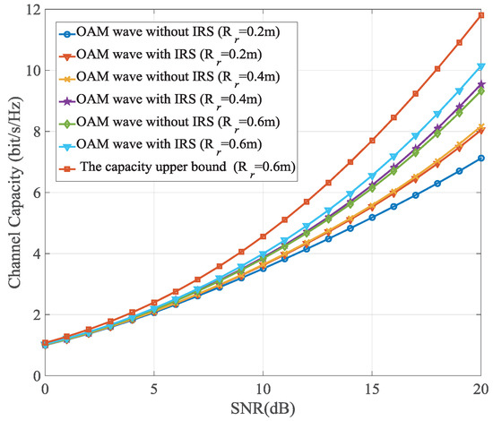
Figure 2.
The channel capacity with IRS and without IRS in passive case.
3.2. Simulation of Special Case with Symmetrical IRS Center
Considering an IRS assisting OAM transmission in special scenarios, it is assumed that the placement of the IRS is not affected by the environment. It can be placed centrally and symmetrically and is equivalent to a larger-radius UCA. At this time, the BS generates OAM wave with a mode of l. In order to maximize the energy received by the IRS, the IRS is placed along the main beam direction of the OAM wave, and the receiver of the SBSC is also along the main OAM beam generated by the equivalent UCA. When placing the IRS and the SBSC according to the above method, the distance between the IRS and the BS is set to 100 m, the number of IRSs is 10, and the number of internal elements is 16. The radius of the BS antenna is set from m to m. In order to generate an OAM beam, the distances between the IRS and the BS and between the IRS and the SBSC need to meet the far-field conditions. In the cases of achieving the receiving effect along the main OAM beam direction with and without the assistance of a passive IRS, Figure 3 shows the relationship between the UCA radius required by the receiver to achieve the same received energy and the BS antenna radius . When transmitting different OAM modes, as the radius of the transmitting antenna increases, the divergence angles of different OAM modes decrease. Therefore, in both cases (with and without IRS), decreases as increases. For simplicity, only the assistance of the passive IRS is considered.
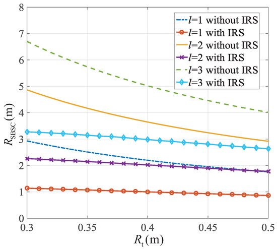
Figure 3.
The required receiving radius of the SBSC when the same received signal strength is achieved.
When the passive IRS is used to achieve the same received energy within the range of the selected transmitting antenna , the antenna size of the SBSC only needs to be half or even less than the original size. The IRS achieves the effect of converging OAM beams. However, due to the large radius of the UCA equivalent to the IRS, the number of elements constituting the UCA affects the generation of the OAM beam, and the effective range of maintaining the vortex phase characteristics changes. As a special case, when and 16, the phase distribution of the OAM is as shown in Figure 4 by Feko simulation to illustrate the influence of the number of on the effective vortex range. In the far-field formula for generating OAM, when the number of antennas approaches infinity, the generated OAM is ideal. The pre-phase change effect impacts the purity of the OAM during its transmission and further affects the BER in the receiving and decoding processes through mode crosstalk. The UCA radius equivalent to IRS is 1 m. The larger the number of , the larger the effective vortex range. When is small, the effective vortex range becomes smaller due to the influence of the grating lobe effect. When , the effective radius for presenting the vortex phase distribution is 0.5 m. When , the effective radius for presenting the vortex phase distribution is 1.7 m.
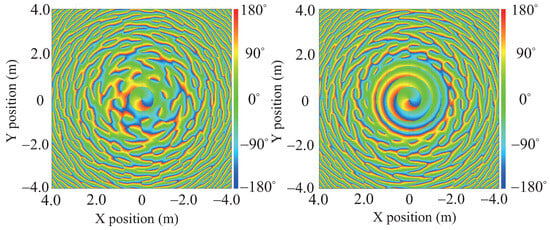
Figure 4.
Phase front of electric field strength with and 16 when frequency is 10 GHz.
It is concluded from the simulation results that the introduction of the IRS enables the receiving end to have the same or even greater received signal energy than that received along the main direction of the OAM beams generated by the BS in the case of a small radius. In addition, when the number of elements N remains unchanged, the increase in the UCA radius reduces the beam width of the main lobe and reduces the range of spatial elevation angle to maintain the OAM vortex characteristics, but the reception in the main beam direction is not affected by the grating lobe effect, which provides a theoretical basis indicating the feasibility of using IRSs to assist in the transmission of OAM beams.
4. Discussion
The introduction of IRSs into OAM communication systems provides a new approach to mitigating beam divergence, reducing the impact of LoS blockage, and improving channel capacity. By optimizing the deployment position, the IRS not only effectively reduces the size of the receiver antenna but also significantly extends the transmission distance. Building on this foundation, dynamic IRS control will be further implemented in the future, enabling real-time adaptive adjustment of its phase and amplitude in response to changes in channel conditions and user movement. However, practical applications still face numerous technical challenges, including high-precision calibration of the IRS, accurate delay synchronization between the direct and reflected paths, and complex interference suppression in multi-user or multi-IRS scenarios. In subsequent work, the communication efficiency and robustness of the system will be enhanced through efficient channel estimation algorithms, robust beam control strategies, and intelligent optimization methods driven by machine learning.
Multipath fading impairs the orthogonality between OAM modes, while reflection loss reduces the effective radiated power of the IRS and diminishes its convergence effect on OAM. Quantization error degrades beam pointing accuracy, also lowering the effective radiated power of the IRS. Specifically, the hardware constraints of the IRS affect the channel model. Since this paper mainly focuses on the construction of the channel model under ideal conditions, the performance impact of non-ideal conditions caused by IRS hardware constraints will be further considered in future research. The simulation under the random placement method in this paper considers a specific scenario of random IRS distribution. The performance analysis of all IRS scenarios, including confidence interval and variance indicators, will be carried out in future research.
5. Conclusions
The additional channel constructed by the IRS can converge divergent OAM beams, further improving the performance of the transmission system and achieving the effects of increasing channel capacity and reducing receiver size. In this paper, an IRS-aided orbital angular momentum (OAM) transmission system is constructed. Furthermore, the channel model of the system is presented. Signals reflected by the IRS can be expanded to each OAM mode component, thus enhancing the transmission of the OAM. In LoS scenarios, a randomly placed IRS is equivalent to adding a new information path for OAM transmission. Its most intuitive advantage is improving the channel capacity of the entire communication system. However, due to the greater path attenuation caused by secondary reflection, the increase in channel capacity is limited, at approximately 1 bit/s/Hz. In special cases, when the IRS is placed symmetrically and uniformly on the transmission path, it can be equivalent to a coaxial multi-ring uniform circular array (UCA). The IRS-aided OAM communication system in this special case can more efficiently converge OAM waves, and its main advantage is effectively reducing the antenna size required at the receiver side to achieve the same reception effect. Specifically, it can reduce the size to approximately half of the original antenna size. The core value of the integration of IRS and OAM lies not only in beam enhancement but more importantly in the ability to reconstruct physical-layer degrees of freedom. Parabolic antennas only adapt to a single transmission distance and suffer from the problem of mechanical bulkiness. Active phased arrays compensate for beam divergence by dynamically adjusting the phases of array elements. However, adaptive beamforming is plagued by high power consumption and high hardware complexity—each array element requires an independent radio frequency link, leading to a significant increase in costs. Additionally, adaptive beamforming also has field-of-view limitations. The IRS–OAM integration scheme dynamically reconstructs phase and amplitude, and passive IRS greatly reduces transmission power consumption. Meanwhile, IRS features flexible deployment capability, as it enables the construction of auxiliary channels by attaching ultra-thin curved surfaces to objects in the environment.
The two promising research directions in IRS-assisted OAM communication at present are active intelligent reflecting surfaces and larger-scale arrays. Active intelligent reflecting surfaces are expected to compensate for the electromagnetic wave transmission loss caused by the propagation path during OAM transmission. The introduction of larger-scale arrays can achieve stronger focusing capability. Both methods can further assist OAM transmission systems in improving channel capacity.
Author Contributions
Conceptualization, Q.W. and Y.Z.; methodology, Q.W. and Y.Z.; software, Q.W., S.L., and Y.L.; validation, Y.Z.; formal analysis, Y.Z. and D.L.; resources, Q.W.; data curation, S.L. and Y.L.; writing—original draft preparation, Q.W.; writing—review and editing, Y.Z. and D.L.; visualization, S.L. and Y.L.; supervision, Q.W. and Y.Z.; project administration, Q.W. and Y.Z.; funding acquisition, Q.W. and Y.Z.; reviewing and revising, X.J. All authors have read and agreed to the published version of this manuscript.
Funding
This work is supported by the Scientific Research Start-up Fund of North China University of Technology. It is also supported partly by the National Natural Science Foundation of China (62461041), partly by the Natural Science Foundation of Jiangxi Province (20224BAB212016 & 20242BAB25068).
Data Availability Statement
The data presented in this study are available on request from the corresponding author due to privacy.
Conflicts of Interest
The authors declare no conflicts of interest.
References
- Guo, H.; Liang, Y.; Chen, J.; Larsson, E.G. Weighted sum-rate maximization for reconfigurable intelligent surface aided wireless networks. IEEE Trans. Wireless. Commun. 2020, 19, 3064–3076. [Google Scholar] [CrossRef]
- Liu, C.; Yang, F.; Xu, S.; Li, M. Reconfigurable metasurface: A systematic categorization and recent advances. Electromagn. Sci. 2023, 1, 0040021. [Google Scholar] [CrossRef]
- Feng, Y.; Hu, Q.; Qu, K.; Yang, W.; Zheng, Y.; Chen, K. Reconfigurable intelligent surfaces: Design, implementation, and practical demonstration. Electromagn. Sci. 2023, 1, 0020111. [Google Scholar] [CrossRef]
- Micallef, T.; Hussain, I.; Wu, K. Multifunction transceiver for data communication, radar sensing and power transfer. Electromagn. Sci. 2025, 3, 0100491. [Google Scholar] [CrossRef]
- Oyesina, K.A.; Wong, A.M.H. Achieving many-fold reduction in active elements with a highly-directive beam-steerable Huygens box antenna. Electromagn. Sci. 2025, 3, 0100512. [Google Scholar] [CrossRef]
- Wu, Q.; Zhang, R. Towards smart and reconfigurable environment: Intelligent reflecting surface aided wireless network. IEEE Commun. Mag. 2020, 58, 106–112. [Google Scholar] [CrossRef]
- Zhao, Y.; Feng, Y.; Ismail, A.M.; Wang, Z.; Guan, Y.L.; Guo, Y.; Yuen, C. 2-Bit RIS prototyping enhancing rapid-response space-time wavefront manipulation for wireless communication: Experimental studies. IEEE Open J. Commun. Soc. 2024, 5, 4885–4901. [Google Scholar] [CrossRef]
- Zhao, Y.; Guan, Y.L.; Ismail, A.M.; Ju, G.; Lin, D.; Lu, Y.; Yuen, C. Holographic-inspired meta-surfaces exploiting vortex beams for low-interference multipair IoT communications: From theory to prototype. IEEE Internet Things J. 2024, 11, 12660–12675. [Google Scholar] [CrossRef]
- Nadi, M.; Sedighy, S.H.; Cheldavi, A. Multimode OAM beam generation through 1-bit programmable metasurface antenna. Sci. Rep. 2023, 13, 15603–15612. [Google Scholar] [CrossRef]
- Zhang, S.; Zhang, R. Capacity characterization for intelligent reflecting surface aided MIMO communication. IEEE J. Sel. Areas Commun. 2020, 38, 1823–1838. [Google Scholar] [CrossRef]
- Zhang, B.; Chen, Z.N.; Zhou, Y.; Lou, Q.; Wang, J. Mouthaan, K. Improving radiation pattern roundness of henge-like metaring-loaded monopoles above a finite ground for MIMO systems. Electromagn. Sci. 2024, 2, 0060182. [Google Scholar] [CrossRef]
- Zhao, Y.; Lv, Q.; Guan, Y.L.; Ismail, A.M.; Feng, Y.; Wang, Z.; Lin, D.; Niu, H.; Chen, C.; Yuen, C. Free Space Spot-Beamforming for IoT Multi-User Near-Orthogonal Overlay Communications Enhanced by OAM Waves and Reconfigurable Meta-Surface. Electromagn. Sci. 2025, 3, 0110022. [Google Scholar] [CrossRef]
- Willner, A.E.; Huang, H.; Yan, Y.; Ren, Y.; Ahmed, N.; Xie, G.; Bao, C.; Li, L.; Cao, Y.; Zhao, Z.; et al. Optical communications using orbital angular momentum beams. Adv. Opt. Photon. 2015, 7, 66–106. [Google Scholar] [CrossRef]
- Dong, L.; Wang, H.-M. Enhancing secure MIMO transmission via intelligent reflecting surface. IEEE Trans. Wireless. Commun. 2020, 19, 7543–7556. [Google Scholar] [CrossRef]
- Wang, Z.; Wu, Q. Extension of Hannan’s limit: Evaluation and enhancement of beam-scanning performance of planar phased arrays. Electromagn. Sci. 2024, 2, 0080312. [Google Scholar] [CrossRef]
- Zhao, Y.; Zhang, C. Orbital angular momentum beamforming for index modulation with partial arc reception. Electron. Lett. 2019, 55, 1271–1273. [Google Scholar] [CrossRef]
- Fang, X.; Zheng, X.; Li, M.; Li, Z.; Ding, D. Wireless secure communication based on code domain space-time modulated metasurface. Electromagn. Sci. 2024, 2, 0080352. [Google Scholar] [CrossRef]
- Wang, Z.; Liu, L.; Cui, S. Channel estimation for intelligent reflecting surface assisted multiuser communications: Framework, algorithms, and analysis. IEEE Trans. Wireless. Commun. 2020, 19, 6607–6620. [Google Scholar] [CrossRef]
- Wu, Q.; Zhang, S.; Zheng, B.; You, C.; Zhang, R. Intelligent reflecting surface-aided wireless communications: A tutorial. IEEE Trans. Wireless. Commun. 2021, 69, 3313–3351. [Google Scholar] [CrossRef]
- Allen, L.; Beijersbergen, M.W.; Spreeuw, R.J.C.; Woerdman, J.P. Orbital angular momentum of light and the transformation of Laguerre-Gaussian laser modes. Phys. Rev. A 1992, 45, 8185. [Google Scholar] [CrossRef]
- Zhao, Y.; Guan, Y.L.; Chen, D.; Ismail, A.M.; Ma, X.; Liu, X.; Yuen, C. Exploring RCS diversity with novel OAM beams without energy void: An experimental study. IEEE Trans. Veh. Technol. 2025, 74, 8321–8326. [Google Scholar] [CrossRef]
- Zhang, Y.; Guo, Z.; Xu, B.; Zhang, J.; Xiao, H.; Sha, E.I.W.; Ai, B. Performance analysis of non-paraxial deployments continuous aperture MIMO for electromagnetic information theory. Electromagn. Sci. 2025, early access.
- Zhu, Q.B.; Jiang, T.; Qu, D.M.; Chen, D.; Zhou, N.R. Radio vortex multiple-input multiple-output communication systems with high capacity. IEEE Access 2015, 3, 2456–2464. [Google Scholar] [CrossRef]
- Yuri, K.; Honma, N.; Murata, K. Mode selection method suitable for dual-circular-polarized OAM transmission. IEEE Trans. Antennas Propag. 2019, 67, 4878–4882. [Google Scholar] [CrossRef]
- Zhao, N.; Li, X.; Li, G.; Kahn, J.M. Capacity limits of spatially multiplexed free-space communication. Nat. Photon. 2015, 9, 822–826. [Google Scholar] [CrossRef]
- Zhao, Y.; Ma, X.; Guan, Y.L.; Liu, Y.; Ismail, A.M.; Liu, X.; Yeo, S.Y.; Yuen, C. Near-orthogonal overlay communications in LoS channel enabled by novel OAM beams without central energy voids: An experimental study. IEEE Internet Things J. 2024, 11, 39697–39708. [Google Scholar] [CrossRef]
- Thidé, B.; Then, H.; Sjöholm, J.; Palmer, K.; Bergman, J.; Carozzi, T.D.; Istomin, Y.N.; Ibragimov, N.H.; Khamitova, R. Utilization of photon orbital angular momentum in the low-frequency radio domain. Phys. Rev. Lett. 2007, 99, 087701. [Google Scholar] [CrossRef]
- Mohammadi, S.M.; Daldorff, L.K.; Bergman, J.E.; Karlsson, R.L.; Thidé, B.; Forozesh, K.; Carozzi, T.D.; Isham, B. Orbital angular momentum in radio-A system study. IEEE Trans. Antennas Propag. 2010, 58, 565–572. [Google Scholar] [CrossRef]
- Zhang, C.; Zhao, Y. Orbital angular momentum nondegenerate index mapping for long distance transmission. IEEE Trans. Wireless. Commun. 2019, 18, 5027–5036. [Google Scholar] [CrossRef]
- Long, W.-X.; Chen, R.; Moretti, M.; Li, J. AoA estimation for OAM communication systems with mode-frequency multi-time ESPRIT method. IEEE Trans. Veh. Technol. 2021, 70, 5094–5098. [Google Scholar] [CrossRef]
- Nguyen, D.K.; Pascal, O.; Sokoloff, J.; Chabory, A.; Palacin, B.; Capet, N. Antenna gain and link budget for waves carrying orbital angular momentum. Radio Sci. 2015, 50, 1165–1175. [Google Scholar] [CrossRef]
- Zhao, Y.; Wang, Z.; Lu, Y.; Guan, Y.L. Multimode OAM convergent transmission with co-divergent angle tailored by Airy wavefront. IEEE Trans. Antennas Propag. 2023, 71, 5256–5265. [Google Scholar] [CrossRef]
- Zhao, Y.; Zhang, C. Compound angular lens for radio orbital angular momentum coaxial separation and convergence. IEEE Antennas Wirel. Propag. Lett. 2019, 18, 2160–2164. [Google Scholar] [CrossRef]
- Zhao, Y.; Zhang, C. Distributed antennas scheme for orbital angular momentum long-distance transmission. IEEE Antennas Wireless Propaga. Lett. 2020, 19, 332–336. [Google Scholar] [CrossRef]
- Chen, R.; Xu, H.; Moretti, M.; Li, J. Beam steering for the misalignment in UCA-based OAM systems. IEEE Wireless Commun. Lett. 2018, 7, 582–585. [Google Scholar] [CrossRef]
- Zhu, Y.; Dang, W.; Liu, X.; Chen, Y.; Zhou, X.; Lu, H. Generation of plane spiral orbital angular momentum using circular double-slot Vivaldi antenna array. Sci. Rep. 2020, 10, 18328–18336. [Google Scholar] [CrossRef]
- Song, J.; Zhang, X.; Chi, H.; Jin, X.; Hui, X. Design of orbital angular momentum antenna array for high-order modes. Electronics 2023, 12, 4891. [Google Scholar] [CrossRef]
- Dhanade, Y.B.; Patnaik, A. Generation of OAM beams with quasi omnidirectional pattern using simple slotted waveguide array. Sci. Rep. 2024, 14, 6514–6520. [Google Scholar] [CrossRef]
- Guo, Z.-G.; Yang, G.-M. Radial uniform circular antenna array for dual-mode OAM generation. IEEE Antennas Wirel. Propag. Lett. 2016, 16, 404–407. [Google Scholar] [CrossRef]
- Xi, R.; Liu, H.; Li, L. Generation and Analysis of High-Gain Orbital Angular Momentum Vortex Wave Using Circular Array and Parasitic EBG with Oblique Incidence. Sci. Rep. 2017, 7, 17363–17370. [Google Scholar] [CrossRef]
- Marvasti, M.; Ghayekhloo, A.; Boutayeb, H. Parabolic reflector antenna design to generate pure high order vortex modes at 24 GHz. In Proceedings of the 2023 International Conference on Engineering and Emerging Technologies (ICEET), Istanbul, Turkiye, 27–28 October 2023; pp. 1–3. [Google Scholar]
- Li, F.; Chen, H.; Zhou, Y.; You, J.; Panoiu, N.C.; Zhou, P.; Deng, L. Generation and Focusing of Orbital Angular Momentum Based on Polarized Reflectarray at Microwave Frequency. IEEE Trans. Microwave Theory Tech. 2020, 69, 1829–1837. [Google Scholar] [CrossRef]
- Barnett, S.M.; Allen, L. Orbital angular momentum and nonparaxial light beams. Opt. Commun. 1994, 110, 670–678. [Google Scholar] [CrossRef]
- Mair, A.; Vaziri, A.; Weihs, G.; Zeilinger, A. Entanglement of the orbital angular momentum states of photons. Nature 2001, 412, 313–316. [Google Scholar] [CrossRef]
- Paterson, C. Atmospheric turbulence and orbital angular momentum of single photons for optical communication. Phys. Rev. Lett. 2005, 94, 153901–153904. [Google Scholar] [CrossRef] [PubMed]
- Wang, J.; Yang, J.Y.; Fazal, I.M.; Ahmed, N.; Yan, Y.; Huang, H.; Ren, Y.X.; Yue, Y.; Dolinar, S.; Tur, M.; et al. Terabit free-space data transmission employing orbital angular momentum multiplexing. Nat. Photonics 2012, 6, 488–496. [Google Scholar] [CrossRef]
- Mahmouli, F.E.; Walker, S.D. 4-Gbps uncompressed video transmission over a 60-GHz orbital angular momentum wireless channel. IEEE Wireless Commun. Lett. 2013, 2, 223–226. [Google Scholar] [CrossRef]
- Yan, Y.; Xie, G.D.; Lavery, M.P.J.; Huang, H.; Ahmed, N.; Bao, C.J.; Ren, Y.X.; Cao, Y.W.; Li, L.; Zhao, Z.; et al. High-capacity millimetre-wave communications with orbital angular momentum multiplexing. Nat. Commun. 2014, 5, 4876–4883. [Google Scholar] [CrossRef]
- Oldoni, M.; Spinello, F.; Mari, E.; Parisi, G.; Someda, C.G.; Tamburini, F.; Romanato, F.; Ravanelli, R.A.; Coassini, P.; Thidé, B. Space-Division Demultiplexing in Orbital-Angular-Momentum-Based MIMO Radio Systems. IEEE Trans. Antennas Propag. 2015, 63, 4582–4587. [Google Scholar] [CrossRef]
- Liu, K.; Cheng, Y.Q.; Yang, Z.C.; Wang, H.Q.; Qin, Y.L.; Li, X. Orbital-Angular-Momentum-Based Electromagnetic Vortex Imaging. IEEE Antennas Wireless Propag. Lett. 2015, 14, 711–714. [Google Scholar] [CrossRef]
- Lin, M.T.; Gao, Y.; Liu, P.G.; Liu, J.B. Improved OAM-based radar target detection using uniform concentric circular arrays. Int. J. Antennas Propag. 2016, 2016, 1852659–1852665. [Google Scholar] [CrossRef]
- Lin, M.T.; Gao, Y.; Liu, P.G.; Liu, J.B. Super-resolution orbital angular momentum based radar target detection. Electron. Lett. 2016, 52, 1168–1170. [Google Scholar] [CrossRef]
- Chen, R.; Xu, H.; Li, J.; Zhang, Y. Misalignment-Robust Receiving Scheme for UCA-Based OAM Communication Systems. In Proceedings of the 2017 IEEE 85th Vehicular Technology Conference (VTC Spring), Sydney, NSW, Australia, 4–7 June 2017; pp. 1–5. [Google Scholar]
- Chen, M.L.N.; Jiang, L.J.; Sha, W.E.I. Artificial perfect electric conductor–perfect magnetic conductor anisotropic metasurface for generating orbital angular momentum of microwave with nearly perfect conversion efficiency. J. Appl. Phys. 2016, 119, 064506–064511. [Google Scholar] [CrossRef]
- Chen, M.L.N.; Jiang, L.J.; Sha, W.E.I. Ultrathin complementary metasurface for orbital angular momentum generation at microwave frequencies. IEEE Trans. Antennas Propag. 2017, 65, 396–400. [Google Scholar] [CrossRef]
- Guo, Y.H.; Pu, M.B.; Zhao, Z.Y.; Wang, Y.Q.; Jin, J.J.; Gao, P.; Li, X.; Ma, X.L.; Luo, X.G. Merging geometric phase and plasmon retardation phase in continuously shaped metasurfaces for arbitrary orbital angular momentum generation. ACS Photonics 2016, 3, 2022–2029. [Google Scholar] [CrossRef]
- Li, Y.; Li, X.; Chen, L.W.; Pu, M.B.; Jin, J.J.; Hong, M.H.; Luo, X.G. Orbital angular momentum multiplexing and demultiplexing by a single metasurface. Adv. Opt. Mater. 2017, 5, 1600689–1600695. [Google Scholar] [CrossRef]
- Devlin, R.C.; Ambrosio, A.; Wintz, D.; Oscurato, S.L.; Zhu, A.Y.; Khorasaninejad, M.; Oh, J.; Maddalena, P. Capasso, F. Spin-to-orbital angular momentum conversion in dielectric metasurfaces. Opt. Express 2017, 25, 377–393. [Google Scholar] [CrossRef]
- Chen, M.L.N.; Jiang, L.J.; Sha, W.E.I. Orbital angular momentum generation and detection by geometric-phase based metasurfaces. Appl. Sci. 2018, 8, 362. [Google Scholar] [CrossRef]
- Edfors, O.; Johansson, A.J. Is orbital angular momentum (OAM) based radio communication an unexploited area? IEEE Trans. Antennas Propagat. 2012, 60, 1126–1131. [Google Scholar] [CrossRef]
- Byun, W.J.; Choi, H.D.; Cho, Y.H. Orbital Angular Momentum (OAM) Antennas via Mode Combining Using Reflectarrays/Dual-reflector designs. Sci. Rep. 2017, 7, 13125–13135. [Google Scholar] [CrossRef]
- Chen, R.; Zhou, H.; Moretti, M.; Wang, X.; Li, J. Orbital Angular Momentum Waves: Generation, Detection, and Emerging Applications. IEEE Commun. Surv. Tutor. 2020, 22, 840–868. [Google Scholar] [CrossRef]
- Li, Y.; Jiang, M.; Zhang, G.; Cui, M. Achievable rate maximization for intelligent reflecting surface-assisted orbital angular momentum-based communication systems. IEEE Trans. Veh. Technol. 2021, 70, 7277–7282. [Google Scholar] [CrossRef]
- An, Z.; Zhang, T.; Shen, M.; De Carvalho, E.; Ma, B.; Yi, C.; Song, T. Series-Constellation Feature Based Blind Modulation Recognition for Beyond 5G MIMO-OFDM Systems With Channel Fading. IEEE Trans. Cogn. Commun. Netw. 2022, 8, 793–811. [Google Scholar] [CrossRef]
- He, Z.; Yuan, X. Cascaded channel estimation for large intelligent metasurface assisted massive MIMO. IEEE Wireless Commun. Lett. 2020, 9, 210–214. [Google Scholar] [CrossRef]
- Yan, W.; Yuan, X.; He, Z.Q.; Kuai, X. Passive beamforming and information transfer design for reconfigurable intelligent surfaces aided multiuser MIMO systems. IEEE J. Sel. Areas Commun. 2020, 38, 1793–1808. [Google Scholar] [CrossRef]
- Liu, K.; Liu, H.; Qin, Y.; Cheng, Y.; Wang, S.; Li, X.; Wang, H. Generation of OAM beams using phased array in the microwave band. IEEE Trans. Antennas Propag. 2016, 64, 3850–3857. [Google Scholar] [CrossRef]
Disclaimer/Publisher’s Note: The statements, opinions and data contained in all publications are solely those of the individual author(s) and contributor(s) and not of MDPI and/or the editor(s). MDPI and/or the editor(s) disclaim responsibility for any injury to people or property resulting from any ideas, methods, instructions or products referred to in the content. |
© 2025 by the authors. Licensee MDPI, Basel, Switzerland. This article is an open access article distributed under the terms and conditions of the Creative Commons Attribution (CC BY) license (https://creativecommons.org/licenses/by/4.0/).