

Perovskite-Type Oxides as Exsolution Catalysts in CO2 Utilization


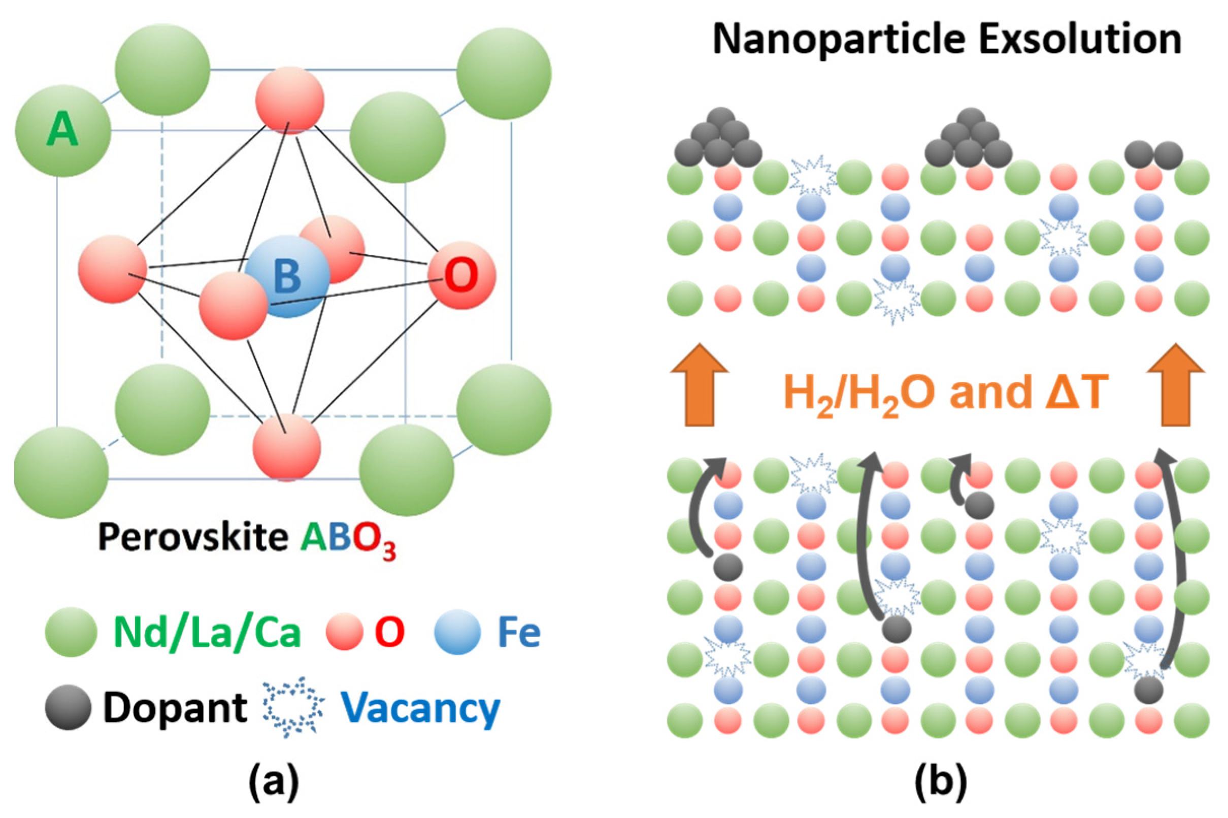
Definition
:
1. Introduction
2. Materials—Synthesis and Characterization
2.1. Synthesis of Perovskites
2.2. X-ray Diffraction
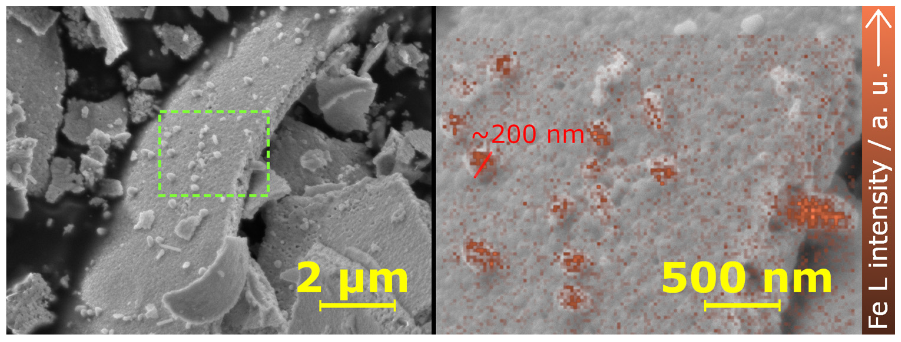
2.3. Micrsocopic Characterization—SEM and TEM
2.4. X-ray Photoelectron Spectroscopy
2.5. Theoretical Modeling
3. Catalytic Tests and In Situ/Operando Measurements
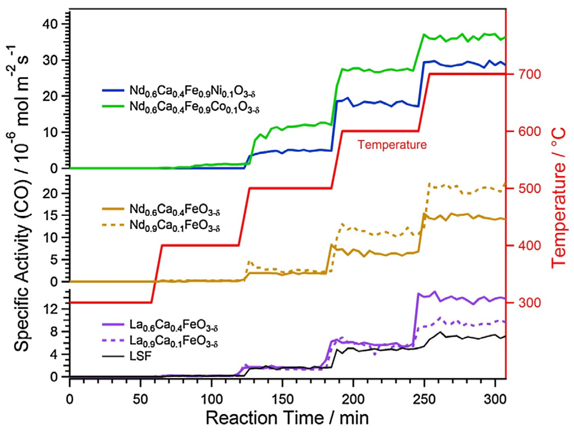
3.1. Catalytic Tests
3.2. In Situ XRD
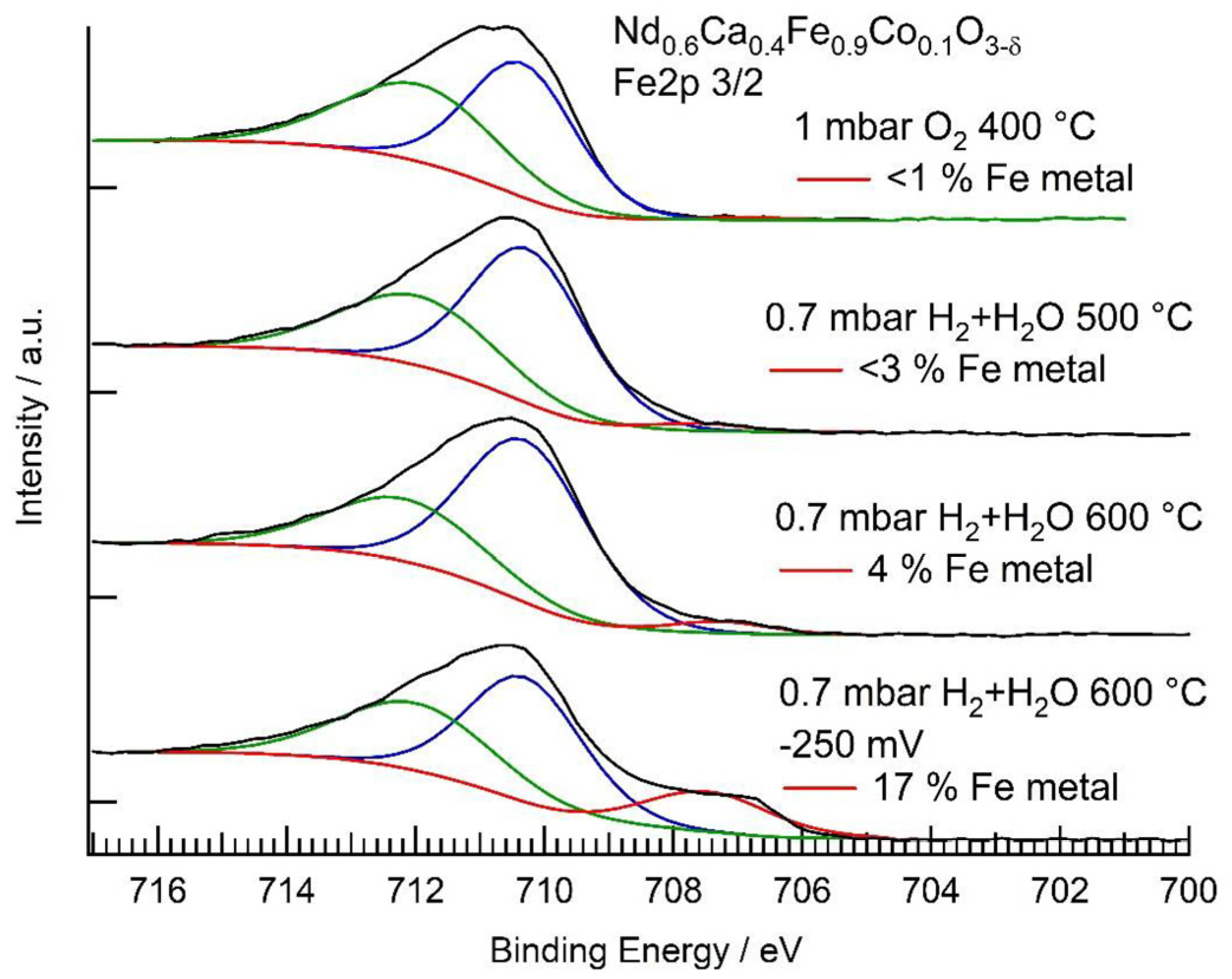
3.3. In Situ XPS
4. Conclusions
- (1)
- The stability of the material: To achieve the synthesis of a phase-pure catalyst, the thermodynamic requirements for forming a stable phase have to be fulfilled. Databases like the one from Bare et al. [39] can be used as guidelines.
- (2)
- A-site composition: Even though materials on the A-site have not been as deeply studied as materials on the B-site, several design principles are common. Lanthanoids such as La, Nd, Pr, or Sm are often used as major components on the A-site. Their ionic radii make them ideally suited elements to use together with transition metals on the B-site. Additionally, divalent ions such as Ca, Sr, or Ba are often doped on the A-site. This promotes the formation of oxygen vacancies and/or the oxidation of other elements in the material, thus enabling exsolution.
- (3)
- B-site composition: The B-site is often made up of one or more transition metals. The main concern in choosing the B-site is the nature of the nanoparticles that one wants to exsolve. Often, the B-site is made from a base element such as Fe or Ti, which is then doped with the desired exsolving element (e.g., Cu, Co, Ni, …). One has to keep in mind that the element to be exsolved should be more easily reducible than the base element.
Author Contributions
Funding
Data Availability Statement
Acknowledgments
Conflicts of Interest
References
- Lynas, M.; Houlton, B.Z.; Perry, S. Greater than 99% consensus on human caused climate change in the peer-reviewed scientific literature. Env. Res. Lett. 2021, 16, 114005. [Google Scholar] [CrossRef]
- Friedlingstein, P.; O’Sullivan, M.; Jones, M.W.; Andrew, R.M.; Gregor, L.; Hauck, J.; Le Quere, C.; Luijkx, I.T.; Olsen, A.; Peters, G.P.; et al. Global Carbon Budget 2022. Earth Syst. Sci. Data 2022, 14, 4811–4900. [Google Scholar] [CrossRef]
- Communication from the Commission to the European Parliament. The European Green Deal. Available online: https://eur-lex.europa.eu/legal-content/EN/TXT/?uri=COM%3A2019%3A640%3AFIN (accessed on 28 September 2023).
- De Luna, P.; Hahn, C.; Higgins, D.; Jaffer, S.A.; Jaramillo, T.F.; Sargent, E.H. What would it take for renewably powered electrosynthesis to displace petrochemical processes? Science 2019, 364, eaav3506. [Google Scholar] [CrossRef] [PubMed]
- Matsubu, J.C.; Yang, V.N.; Christopher, P. Isolated Metal Active Site Concentration and Stability Control Catalytic CO2 Reduction Selectivity. J. Am. Chem. Soc. 2015, 137, 3076–3084. [Google Scholar] [CrossRef]
- Pakhare, D.; Spivey, J. A review of dry (CO2) reforming of methane over noble metal catalysts. Chem. Soc. Rev. 2014, 43, 7813–7837. [Google Scholar] [CrossRef]
- Daza, C.E.; Gallego, J.; Moreno, J.A.; Mondragon, F.; Moreno, S.; Molina, R. CO2 reforming of methane over Ni/Mg/Al/Ce mixed oxides. Catal. Today 2008, 133, 357–366. [Google Scholar] [CrossRef]
- Usman, M.; Daud, W.; Abbas, H.F. Dry reforming of methane: Influence of process parameters-A review. Renew. Sustain. Energy Rev. 2015, 45, 710–744. [Google Scholar] [CrossRef]
- Hou, Z.; Chen, P.; Fang, H.; Zheng, X.; Yashima, T. Production of synthesis gas via methane reforming with CO2 on noble metals and small amount of noble-(Rh-) promoted Ni catalysts. Int. J. Hydrogen Energy 2006, 31, 555–561. [Google Scholar] [CrossRef]
- Lindenthal, L.; Rameshan, R.; Summerer, H.; Ruh, T.; Popovic, J.; Nenning, A.; Löffler, S.; Opitz, A.K.; Blaha, P.; Rameshan, C. Modifying the Surface Structure of Perovskite-Based Catalysts by Nanoparticle Exsolution. Catalysts 2020, 10, 268. [Google Scholar] [CrossRef]
- Hwang, J.; Rao, R.R.; Giordano, L.; Katayama, Y.; Yu, Y.; Shao-Horn, Y. Perovskites in catalysis and electrocatalysis. Science 2017, 358, 751–756. [Google Scholar] [CrossRef]
- Nishihata, Y.; Mizuki, J.; Akao, T.; Tanaka, H.; Uenishi, M.; Kimura, M.; Okamoto, T.; Hamada, N. Self-regeneration of a Pd-perovskite catalyst for automotive emissions control. Nature 2002, 418, 164–167. [Google Scholar] [CrossRef]
- Kwon, O.; Sengodan, S.; Kim, K.; Kim, G.; Jeong, H.Y.; Shin, J.; Ju, Y.W.; Han, J.W. Exsolution trends and co-segregation aspects of self-grown catalyst nanoparticles in perovskites. Nat. Commun. 2017, 8, 15967. [Google Scholar] [CrossRef] [PubMed]
- Neagu, D.; Tsekouras, G.; Miller, D.N.; Menard, H.; Irvine, J.T.S. In situ growth of nanoparticles through control of non-stoichiometry. Nat. Chem. 2013, 5, 916–923. [Google Scholar] [CrossRef]
- Neagu, D.; Oh, T.S.; Miller, D.N.; Menard, H.; Bukhari, S.M.; Gamble, S.R.; Gorte, R.J.; Vohs, J.M.; Irvine, J.T.S. Nano-socketed nickel particles with enhanced coking resistance grown in situ by redox exsolution. Nat. Commun. 2015, 6, 8120. [Google Scholar] [CrossRef] [PubMed]
- Lindenthal, L.; Huber, J.; Drexler, H.; Ruh, T.; Rameshan, R.; Schrenk, F.; Loeffler, S.; Rameshan, C. In Situ Growth of Exsolved Nanoparticles under Varying rWGS Reaction Conditions-A Catalysis and Near Ambient Pressure-XPS Study. Catalysts 2021, 11, 1484. [Google Scholar] [CrossRef]
- Rameshan, R.; Nenning, A.; Raschhofer, J.; Lindenthal, L.; Ruh, T.; Summerer, H.; Opitz, A.K.; Huber, T.M.; Rameshan, C. Novel Sample-Stage for Combined Near Ambient Pressure X-ray Photoelectron Spectroscopy, Catalytic Characterization and Electrochemical Impedance Spectroscopy. Crystals 2020, 10, 947. [Google Scholar] [CrossRef]
- Lindenthal, L.; Ruh, T.; Rameshan, R.; Summerer, H.; Nenning, A.; Herzig, C.; Loffler, S.; Limbeck, A.; Opitz, A.K.; Blaha, P.; et al. Ca-doped rare earth perovskite materials for tailored exsolution of metal nanoparticles. Acta Crystallogr. B 2020, 76, 1055–1070. [Google Scholar] [CrossRef]
- Neagu, D.; Irvine, J.T.S. Enhancing Electronic Conductivity in Strontium Titanates through Correlated A and B-Site Doping. Chem. Mater. 2011, 23, 1607–1617. [Google Scholar] [CrossRef]
- Simmance, K.; Thompsett, D.; Wang, W.L.; Thiebaut, B. Evaluation of perovskite catalysts prepared by flame spray pyrolysis for three-way catalyst activity under simulated gasoline exhaust feeds. Catal. Today 2019, 320, 40–50. [Google Scholar] [CrossRef]
- Koirala, R.; Pratsinis, S.E.; Baiker, A. Synthesis of catalytic materials in flames: Opportunities and challenges. Chem. Soc. Rev. 2016, 45, 3053–3068. [Google Scholar] [CrossRef]
- Assirey, E.A.R. Perovskite synthesis, properties and their related biochemical and industrial application. Saudi Pharm. J. 2019, 27, 817–829. [Google Scholar] [CrossRef] [PubMed]
- Pérez-Coll, D.; Núñez, P.; Frade, J.R.; Abrantes, J.C.C. Conductivity of CGO and CSO ceramics obtained from freeze-dried precursors. Electrochim. Acta 2003, 48, 1551–1557. [Google Scholar] [CrossRef]
- Shandilya, R.; Rai, R.; Singh, J. Review: Hydrothermal technology for smart materials. Adv. Appl. Ceram. 2015, 115, 354–376. [Google Scholar] [CrossRef]
- Ruh, T.; Berkovec, D.; Schrenk, F.; Rameshan, C. Exsolution on perovskite oxides: Morphology and anchorage of nanoparticles. Chem. Comm. 2023, 59, 3948–3956. [Google Scholar] [CrossRef] [PubMed]
- Goodhew, P.J.; Humphreys, J. Electron Microscopy and Analysis; CRC Press: Boca Raton, FL, USA, 2000. [Google Scholar]
- Neagu, D.; Kyriakou, V.; Roiban, I.L.; Aouine, M.; Tang, C.Y.; Caravaca, A.; Kousi, K.; Schreur-Piet, I.; Metcalfe, I.S.; Vernoux, P.; et al. In Situ Observation of Nanoparticle Exsolution from Perovskite Oxides: From Atomic Scale Mechanistic Insight to Nanostructure Tailoring. ACS Nano 2019, 13, 12996–13005. [Google Scholar] [CrossRef]
- Kim, Y.H.; Kang, Y.; Jo, S.; Jeong, H.; Neagu, D.; Myung, J.-H. Shape-shifting nanoparticles on a perovskite oxide for highly stable and active heterogeneous catalysis. J. Chem. Eng. 2022, 441, 136025. [Google Scholar] [CrossRef]
- Schrenk, F.; Lindenthal, L.; Drexler, H.; Rameshan, R.; Summerer, H.; Berger, T.; Ruh, T.; Opitz, A.K.; Rameshan, C. Impact of nanoparticle exsolution on dry reforming of methane: Improving catalytic activity by reductive pre-treatment of perovskite-type catalysts. Appl. Catal. B 2022, 318, 121886. [Google Scholar] [CrossRef]
- Han, J.W.; Park, J.S.; Choi, M.S.; Lee, H. Uncoupling the size and support effects of Ni catalysts for dry reforming of methane. Appl. Catal. B 2017, 203, 625–632. [Google Scholar] [CrossRef]
- Gao, Y.; Chen, D.; Saccoccio, M.; Lu, Z.; Ciucci, F. From material design to mechanism study: Nanoscale Ni exsolution on a highly active A-site deficient anode material for solid oxide fuel cells. Nano Energy 2016, 27, 499–508. [Google Scholar] [CrossRef]
- Merino, N.A.; Barbero, B.P.; Eloy, P.; Cadus, L.E. La1-xCaxCoO3 perovskite-type oxides: Identification of the surface oxygen species by XPS. Appl. Surf. Sci. 2006, 253, 1489–1493. [Google Scholar] [CrossRef]
- Wang, Y.; Ren, W.; Liu, P.R.; Zhao, H.J.; Chen, J.; Deng, J.X.; Xing, X.R. Improved conductivity of NdFeO3 through partial substitution of Nd by Ca: A theoretical study. Phys. Chem. Chem. Phys. 2015, 17, 29097–29102. [Google Scholar] [CrossRef]
- Pishahang, M.; Mohn, C.E.; Stolen, S.; Bakken, E. DFT-study of the energetics of perovskite-type oxides LaMO3 (M = Sc-Cu). RSC Adv. 2012, 2, 10667–10672. [Google Scholar] [CrossRef]
- Torres, A.; Luque, F.J.; Tortajada, J.; Arroyo-de Dompablo, M.E. DFT investigation of Ca mobility in reduced-perovskite and oxidized-marokite oxides. Energy Storage Mater. 2019, 21, 354–360. [Google Scholar] [CrossRef]
- Wexler, R.B.; Gautam, G.S.; Stechel, E.B.; Carter, E.A. Factors Governing Oxygen Vacancy Formation in Oxide Perovskites. J. Am. Chem. Soc. 2021, 143, 13212–13227. [Google Scholar] [CrossRef]
- Cardona, J.F.Z.; Sacanell, J.; Barral, M.A.A.; Vildosola, V.; Viva, F. CO2 reduction on a nanostructured La0.5Ba0.5CoO3 perovskite: Electrochemical characterization and DFT calculations. J. CO2 Util. 2022, 59, 101973. [Google Scholar] [CrossRef]
- Huang, R.; Lim, C.; Jang, M.G.; Hwang, J.Y.; Han, J.W. Exsolved metal-boosted active perovskite oxide catalyst for stable water gas shift reaction. J. Catal. 2021, 400, 148–159. [Google Scholar] [CrossRef]
- Bare, Z.J.L.; Morelock, R.J.; Musgrave, C.B. Dataset of theoretical multinary perovskite oxides. Sci. Data 2023, 10, 244. [Google Scholar] [CrossRef] [PubMed]
- Say, Z.; Dogac, M.; Vovk, E.I.; Kalay, Y.E.; Kim, C.H.; Li, W.; Ozensoy, E. Palladium doped perovskite-based NO oxidation catalysts: The role of Pd and B-sites for NOx adsorption behavior via in-situ spectroscopy. Appl. Catal. B 2014, 154, 51–61. [Google Scholar] [CrossRef]
- Maneerung, T.; Hidajat, K.; Kawi, S. K-doped LaNiO3 perovskite for high-temperature water-gas shift of reformate gas: Role of potassium on suppressing methanation. Int. J. Hydrogen Energy 2017, 42, 9840–9857. [Google Scholar] [CrossRef]
- Qi, R.; Jin, R.; An, L.; Bai, X.; Wang, Z.-J. A Ni/perovskite catalyst with low metal content for CO2 reforming of methane. Catal. Commun. 2022, 163, 106419. [Google Scholar] [CrossRef]
- Lai, K.Y.; Manthiram, A. Self-Regenerating Co-Fe Nanoparticles on Perovskite Oxides as a Hydrocarbon Fuel Oxidation Catalyst in Solid Oxide Fuel Cells. Chem. Mater. 2018, 30, 2515–2525. [Google Scholar] [CrossRef]
- Lindenthal, L.; Popovic, J.; Rameshan, R.; Huber, J.; Schrenk, F.; Ruh, T.; Nenning, A.; Löffler, S.; Opitz, A.K.; Rameshan, C. Novel perovskite catalysts for CO2 utilization—Exsolution enhanced reverse water-gas shift activity. Appl. Catal. B 2021, 292, 120183. [Google Scholar] [CrossRef]
- Efimov, K.; Czuprat, O.; Feldhoff, A. In-situ X-ray diffraction study of carbonate formation and decomposition in perovskite-type BCFZ. J. Solid State Chem. 2011, 184, 1085–1089. [Google Scholar] [CrossRef]
- Deka, D.J.; Kim, J.; Gunduz, S.; Aouine, M.; Millet, J.M.M.; Co, A.C.; Ozkan, U.S. Investigation of hetero-phases grown via in-situ exsolution on a Ni-doped (La,Sr)FeO3 cathode and the resultant activity enhancement in CO2 reduction. Appl. Catal. B 2021, 286, 119917. [Google Scholar] [CrossRef]
- Zhang, T.; Zhao, Y.; Zhang, X.; Zhang, H.; Yu, N.; Liu, T.; Wang, Y. Thermal Stability of an in Situ Exsolved Nanoparticle Structured Perovskite Type Hydrogen Electrode for Solid Oxide Cells. ACS Sustain. Chem. Eng. 2019, 7, 17834–17844. [Google Scholar] [CrossRef]


| Catalyst | Surface Area m2 g−1 | Specific Activity 10−6 mol m−2 s−1 | WHSV L g−1 h−1 |
|---|---|---|---|
| La0.9Ca0.1FeO3-δ | 3.8 | 5.7 | 24.6 |
| La0.6Ca0.4FeO3-δ | 2.8 | 5.9 | 34.1 |
| Nd0.9Ca0.1FeO3-δ | 2.2 | 11.3 | 32.7 |
| Nd0.6Ca0.4FeO3-δ | 1.5 | 6.6 | 20.5 |
| Nd0.6Ca0.4Fe0.9Ni0.1O3-δ | 1.6 | 18.0 | 36.0 |
| Nd0.6Ca0.4Fe0.9Co0.1O3-δ | 1.2 | 27.2 | 32.1 |
| commercial LSF | 5.7 | 4.8 | 28.8 |
Disclaimer/Publisher’s Note: The statements, opinions and data contained in all publications are solely those of the individual author(s) and contributor(s) and not of MDPI and/or the editor(s). MDPI and/or the editor(s) disclaim responsibility for any injury to people or property resulting from any ideas, methods, instructions or products referred to in the content. |
© 2023 by the authors. Licensee MDPI, Basel, Switzerland. This article is an open access article distributed under the terms and conditions of the Creative Commons Attribution (CC BY) license (https://creativecommons.org/licenses/by/4.0/).
Share and Cite
Ruh, T.; Schrenk, F.; Berger, T.; Rameshan, C. Perovskite-Type Oxides as Exsolution Catalysts in CO2 Utilization. Encyclopedia 2023, 3, 1461-1473. https://doi.org/10.3390/encyclopedia3040104
Ruh T, Schrenk F, Berger T, Rameshan C. Perovskite-Type Oxides as Exsolution Catalysts in CO2 Utilization. Encyclopedia. 2023; 3(4):1461-1473. https://doi.org/10.3390/encyclopedia3040104
Chicago/Turabian StyleRuh, Thomas, Florian Schrenk, Tobias Berger, and Christoph Rameshan. 2023. "Perovskite-Type Oxides as Exsolution Catalysts in CO2 Utilization" Encyclopedia 3, no. 4: 1461-1473. https://doi.org/10.3390/encyclopedia3040104
APA StyleRuh, T., Schrenk, F., Berger, T., & Rameshan, C. (2023). Perovskite-Type Oxides as Exsolution Catalysts in CO2 Utilization. Encyclopedia, 3(4), 1461-1473. https://doi.org/10.3390/encyclopedia3040104