Systematic Review

Integrating Reverse Engineering for Digital Model Reconstruction and Remanufacturing of Mechanical Components: A Systematic Review

by
Binoy Debnath
1,*,
Zahra Pourfarash
1,
Bhairavsingh Ghorpade
2,3 and
Shivakumar Raman
1
1
School of Industrial and Systems Engineering, The University of Oklahoma, Norman, OK 73019, USA
2
The Knudsen Institute, Chickasha, OK 73023, USA
3
Space Cow LLC, Austin, TX 78736, USA
*
Author to whom correspondence should be addressed.
Metrology 2025, 5(4), 66; https://doi.org/10.3390/metrology5040066
Submission received: 15 July 2025 / Revised: 5 October 2025 / Accepted: 30 October 2025 / Published: 5 November 2025

Abstract

Reverse engineering (RE) is increasingly recognized as a vital methodology for reconstructing mechanical components, particularly in high-value sectors such as aerospace, transportation, and energy, where technical documentation is often missing or outdated. This study presents a systematic review that investigates the application, challenges, and future directions of RE in mechanical component reconstruction. Adopting the Preferred Reporting Items for Systematic Reviews and Meta-Analyses (PRISMA) framework, 68 peer-reviewed studies were identified, screened, and synthesized. The review highlights RE applications in restoration, redesign, internal geometry modeling, and simulation-driven performance assessment, leveraging technologies such as 3D scanning, CAD modeling, and finite element analysis. However, persistent challenges remain across five domains: product complexity, tolerance and dimensional variations, scanning limitations, integration barriers, and human-material-process dependencies, which hinder automation, accuracy, and manufacturability. Future research opportunities include the automated conversion of point cloud data into editable boundary representation (B-rep) models and AI-driven approaches for feature recognition, geometry reconstruction, and the generation of simulation-ready models. Additionally, advancements in scanning techniques to capture hidden or internal features more effectively are crucial. Overall, this review provides a comprehensive synthesis of current practices and challenges while proposing pathways to advance RE in industrial applications, fostering greater automation, accuracy, and integration in digital manufacturing workflows.

1. Introduction

Reverse engineering (RE) in computer-aided design (CAD) involves the acquisition of the surface geometry of a physical component and the conversion of this geometry into a complete three-dimensional (3D) digital model. Such a model is primarily constructed from a point cloud that is usually extracted using sophisticated scanning technologies [1,2]. RE is recognized in complex product systems (CoPS) as a strategic approach to innovating ways of developing and finalizing the Technical Data Package (TDP), unveiling knowledge about embedded design, and enabling the new product development [3]. When an original part is missing, damaged, or when reproduction is so expensive that RE becomes the only available option, the value of RE for the design engineer is maximized. It provides a methodical approach to either replicating the designs of existing parts or creating functional replacements, repairing broken structures, correcting inaccuracies in digital models, or verifying with inspection [4]. Many companies have adopted RE to extract design information and capture embedded features from existing products. This capability can accelerate innovation and support market entry, even for organizations without full in-house manufacturing capabilities [3]. In many practical situations, the need to recreate a CAD model arises because both 2D and 3D drawings of a part are missing from a company’s archives. This issue is more common than often assumed [5]. While traditional manufacturing begins with a conceptual design and progresses toward physical production, RE works in the opposite direction, starting with a physical object and creating its digital representation. This fundamental difference in direction and data flow is illustrated in Figure 1, which contrasts the conventional manufacturing sequence with the RE workflow.
Furthermore, there are numerous justifications for utilizing RE as an effective engineering design strategy. These include instances where the original equipment manufacturer (OEM) of a part is no longer operational and technical information about the part is unavailable. In such instances, it is necessary to gain insights into the technical characteristics of the part, including dimensions, surface, and quality parameters. Therefore, RE plays a vital role in acquiring some of these details to expedite market entry. These details are necessary for quality control in production and future product modifications [6,7,8]. Competing manufacturers may purchase and dismantle new cars to understand their construction and functionality, similar to how good source code in software engineering often draws inspiration from existing code, while in industries like automotive styling, physical models like clay or foam are used for design, necessitating CAD models for production [7].
RE is utilized in a multitude of industries, including automotive and industrial manufacturing, medical applications, design engineering, marketing enhancement, as well as in the electronic and software sectors. It is also deployed in domains grappling with issues of product piracy [6,9]. In industries such as aerospace, transportation, and energy, aging equipment poses a formidable challenge due to the scarcity of technical records. The absence of dependable 3D data for manufacturing highlights persistent hurdles stemming from aging machinery, process inefficiencies, and the unavailability of digital data, influenced by factors such as legal constraints and trade secrecy [10]. The RE process for mechanical parts involves first sensing their geometry and then transferring the gathered data to a compatible CAD/CAM system for manufacturing. To replicate the part accurately, RE requires extracting sufficient information about the specific part instance using appropriate fabrication methods, while also addressing significant challenges to ensure high accuracy and practical utility of the models derived from sensed data in the manufacturing process [11].
RE has been effectively employed to manufacture numerous mechanical components like seals, O-rings, bolts, nuts, gaskets, and engine parts, playing a significant role across various industries [12]. In industrial settings, when essential components like fan blades encounter failure or become obsolete, the practice of RE offers a powerful solution. When these components need replacement, the availability of supply or distribution channels can alleviate concerns. However, the situation becomes complex when the original product is no longer accessible or lacks detailed specifications. In such cases, industrial site owners are confronted with the task of finding alternative solutions, emphasizing the importance of adaptability and innovative problem-solving in industrial management to ensure operational continuity and efficiency [13]. CAD and simulation tools play a vital role in various industries, particularly in vehicle design, where computer-based surface models are essential. These models rely on point cloud data acquired from stationary scanning devices, such as laser-range or computed tomography scanners, enabling precise surface reconstruction for effective product development and analysis [14].
A variety of industries, including aerospace, transportation, and energy, possess equipment that is decades old, often lacking accessible or existing technical and manufacturing documentation due to their prolonged usage [10]. RE finds application in crafting intricate surface designs for complex mechanical components, while also assisting aerospace companies, such as Boeing, in digitizing legacy data for modern CAD environments. An airplane is a highly engineered system, where each component is carefully designed to serve a specific function. These design decisions often reflect the unique perspectives and priorities of the engineers involved, resulting in a wide variety of aircraft types. Aircraft safety relies on the precise coordination of numerous components that contribute to a safe and stable environment for passengers during flight [15]. RE has acquired high importance in the aviation sector due to the rapid technological advancements and an ever-increasing need for extensive digital documentation. Leading aerospace manufacturers, such as Boeing, have adopted RE techniques to digitize spare part inventories and convert obsolete design files into modern CAD formats [14]. Javidrad and Rahmati [16] used a RE framework for aerospace components integrating materials analysis, CAD reconstruction, and simulation-based validation. They demonstrated the potential for increasing manufacturing capability by modifying welding practices and substituting certain materials. The results, validated by finite element analysis (FEA) and physical tests, clearly show that RE is not just about replication, but also supports functional redesign under actual scenarios. In a broader sense, RE has helped modernize aerospace systems by improving design workflows, inspection techniques, and manufacturing practices, thereby supporting its usefulness in maintaining and developing the aviation industry.
While several prior studies have contributed valuable insights into various aspects of RE through literature reviews, notable limitations remain in their scope, particularly when it comes to the practical reconstruction of mechanical components using real-world scanning technologies. Buonamici et al. [17] offered a structured survey of RE modeling strategies, focusing on CAD reconstruction, segmentation, and surface fitting. However, their discussion centers on classification and software tools, with limited exploration of internal geometries, scan data fidelity, or downstream usability of reconstructed parts. Raibulet et al. [18] reviewed model-driven RE approaches, but they are primarily oriented toward abstract model generation in software and systems engineering. They highlight gaps in industrial validation, standardization, and tool integration, yet do not address physical part reconstruction, 3D scanning challenges, or mechanical domain-specific modeling. Kumar et al. [14] provided a descriptive overview of RE processes in product manufacturing, but fell short of analyzing method-specific trade-offs or practical scanning challenges. Curtis et al. [19] examined the fundamentals of RE barriers and proposed a conceptual framework for designing mechanical components to inhibit RE. The study identified example design features that can obscure design intent but did not engage with scanning, modeling, or the RE process itself. Anwer and Mathieu [9] investigated the foundations of geometric RE through the lens of shape engineering, proposing curvature-based segmentation and clustering methods, and emphasizing the role of shape descriptors and feature recognition. While their work addressed conceptual and computational challenges in shape processing, it did not evaluate scanner-specific performance or reconstruct internal geometries, or integrate downstream into simulation and lifecycle contexts. Wakjira et al. [20] reviewed RE applications in the medical domain, integrating CT, MRI, and CAD modeling for personalized medical devices. However, their focus remained on biomedical reconstruction and proof-of-concept applications, without a comparative evaluation of scanner performance or an examination of challenges in mechanical parts. In contrast, the present study discusses the practical applications of RE in mechanical component reconstruction, identifies real-world challenges in scanning and modeling, and directly addresses these through scanner-specific evaluation, internal geometry recovery, and assessment of model usability for simulation and lifecycle tasks, which previous studies have not comprehensively explored. To systematically address the research gaps identified in the existing literature, this study formulated the following research questions (RQs) to guide its investigation:
  • RQ1: How is reverse engineering applied in the restoration, remanufacturing, and redesign of mechanical components across different sectors?
  • RQ2: What methods are most effective for reconstructing internal geometries and integrating RE with simulation and analysis tools?
  • RQ3: How are AI and automation advancing RE workflows, particularly in data processing, model reconstruction, and error reduction?
  • RQ4: What are the major challenges, including tolerance deviations, scanning limitations, and human/material factors, that affect the fidelity and usability of RE outputs?
  • RQ5: What emerging trends and future research directions can enhance the integration of RE with manufacturing processes, and lifecycle management?
To address these research questions, this study adopted a structured scoping review approach, enabling the identification, organization, and analysis of relevant studies in a transparent and replicable manner to address those RQs. This method ensured comprehensive coverage of the domain, facilitated gap detection, and supported the formulation of evidence-based insights into RE practices for mechanical components.
The rest of the paper is structured as follows: Section 2 details the methodology employed for the systematic scoping review, including the review protocol, search strategy, and inclusion/exclusion criteria. Section 3 synthesizes the findings across key application areas such as restoration, internal feature reconstruction, AI-driven approaches, and scanning technology trends. Section 4 presents the challenges identified in existing studies, categorized under five thematic areas. Section 5 discusses future research directions emerging from the gap analysis. Finally, Section 6 concludes the paper by summarizing the key insights and contributions of the study.

2. Methodology

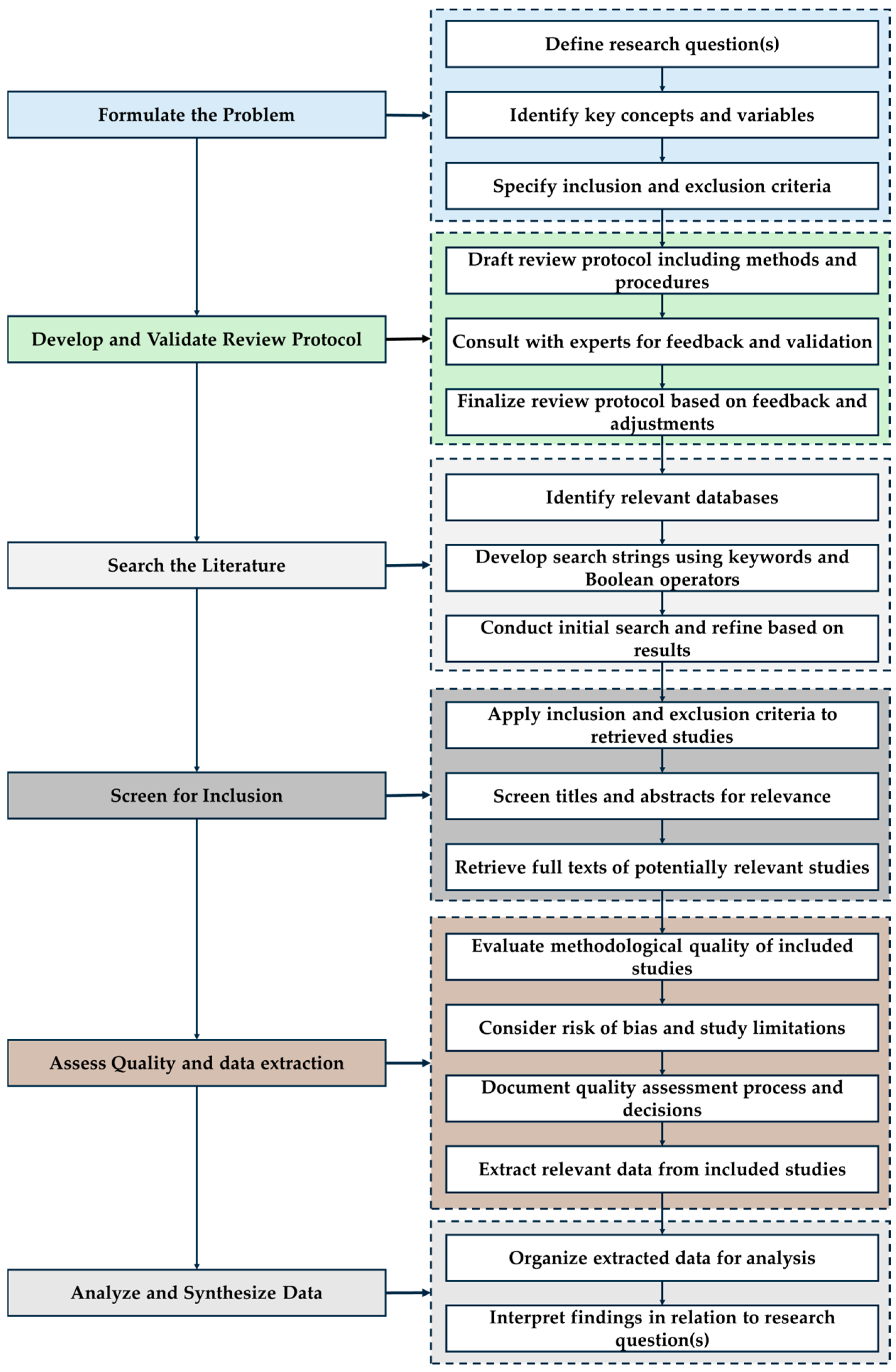
This study employed a systematic review approach to investigate the role of RE in mechanical component analysis, with a specific focus on aerospace and precision engineering contexts. The methodology was developed in accordance with the PRISMA framework [21] and executed through a multi-phase process that encompassed problem formulation, protocol validation, literature search, screening, quality assessment, and synthesis. The overall process is visually presented in Figure 2, which illustrates the structured flow from initial conceptualization to data analysis.
The review began with the proper formulation of RQs that aimed to capture both the technological and implementation aspects of RE in mechanical components. This involved identifying key variables such as applications, geometric fidelity, tolerance variation, post-processing effects, and internal feature reconstruction, all of which play a critical role in influencing the success of RE practices in industrial applications.

2.1. Literature Search Strategy

A comprehensive review protocol was developed and refined through expert consultations. Feedback from researchers specializing in RE and manufacturing helped in shaping a more rigorous and focused protocol. A review protocol was developed a priori in alignment with the PRISMA 2020 guidelines. The protocol defined the RQs (stated in Introduction section), eligibility criteria, and data extraction approach. The protocol was not registered in any public repository, which may limit reproducibility. The final research protocol is summarized in Table 1, which outlines the core parameters of the review, including the selected databases, the use of Boolean logic with keyword clusters, the time frame from 2005 to 2025, and specific inclusion and exclusion criteria. Only peer-reviewed publications written in English and presenting empirical findings—such as case studies, simulations, or experiments—were considered. Studies were excluded if they were not peer-reviewed, lacked sufficient methodological detail, or were not aligned with the RQs.
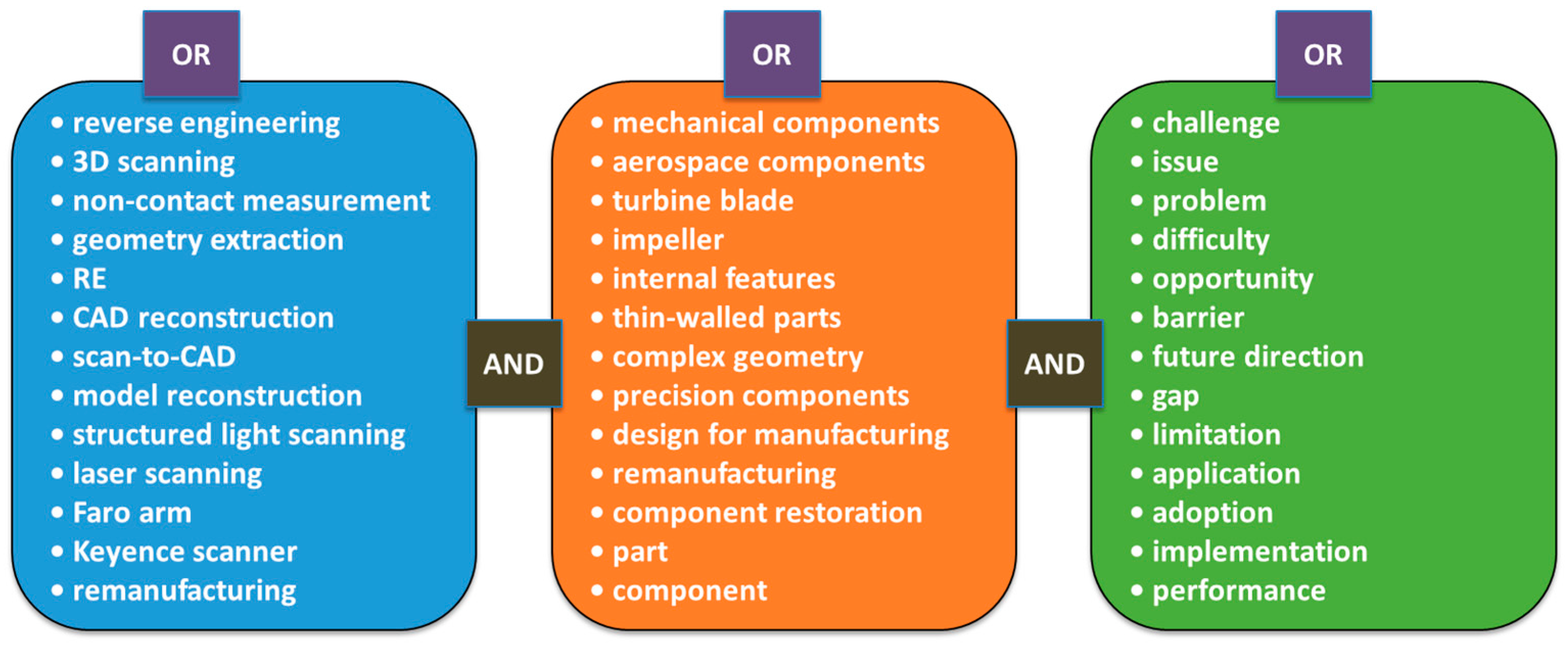
The search strategy was driven by a set of carefully crafted keyword clusters, which were developed to ensure comprehensive coverage of relevant themes. These clusters were visualized in Figure 3, where three major thematic groups were identified: (i) RE technologies and methods, such as “3D scanning,” “CAD reconstruction,” and “non-contact measurement”; (ii) target domains and component types, including “turbine blade,” “impeller,” and “thin-walled parts”; and (iii) contextual and analytical terms like “challenge,” “issue,” “application,” and “performance.” Boolean operators (AND/OR) were used to combine these clusters and ensure that retrieved articles addressed the technological, functional, and implementation-related aspects of RE in mechanical components. This structured approach enabled the targeted retrieval of literature and the capture of studies of high relevance. The search was conducted using this cluster-based query structure across databases, including Google Scholar, Web of Science, Scopus, and the University of Oklahoma Library.

2.2. Selection of Studies Using PRISMA Framework

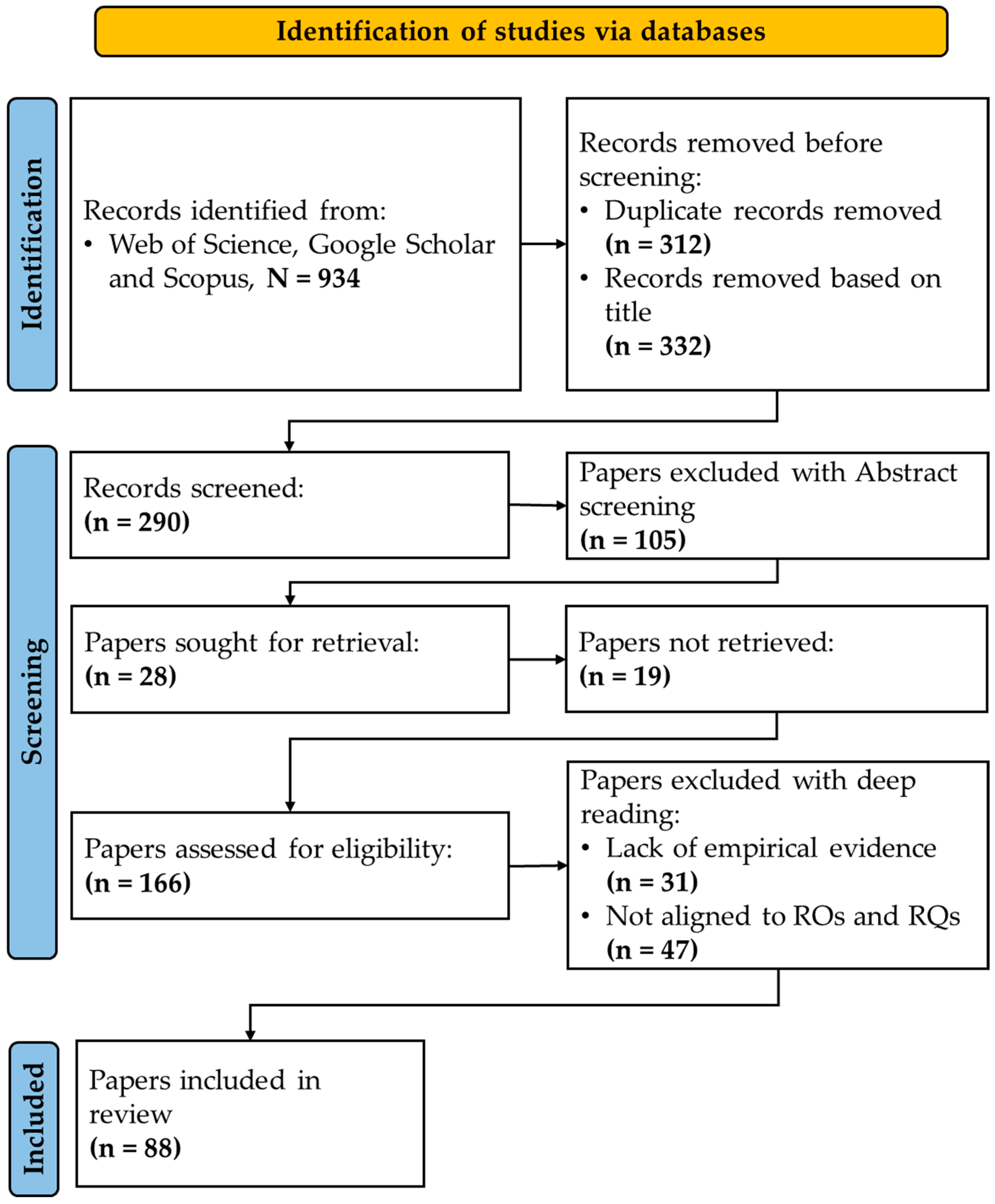
All records retrieved through database searches were imported into Microsoft Excel for initial management and removal of duplicates. The study selection process adhered to the PRISMA flow framework, encompassing four key stages: identification, screening, eligibility evaluation, and final inclusion based on alignment with addressing RQs. As depicted in the PRISMA flow diagram in Figure 4, this strategy initially identified 934 records, which were then screened and reviewed by one reviewer. After removing 312 duplicates, 622 records remained, of which 332 were excluded based on title screening. The remaining 290 records were further screened through an abstract review, followed by a full-text reading. Ultimately, 166 full-text articles were assessed for eligibility, and 88 were deemed relevant and included in the final synthesis. The primary reasons for exclusion included misalignment with the research questions, insufficient technical depth, or a focus on components beyond the scope of mechanical engineering. However, the certainty of evidence was not formally evaluated because the included studies were highly heterogeneous in terms of design, scope, and outcome measures. Therefore, a narrative synthesis approach was adopted.
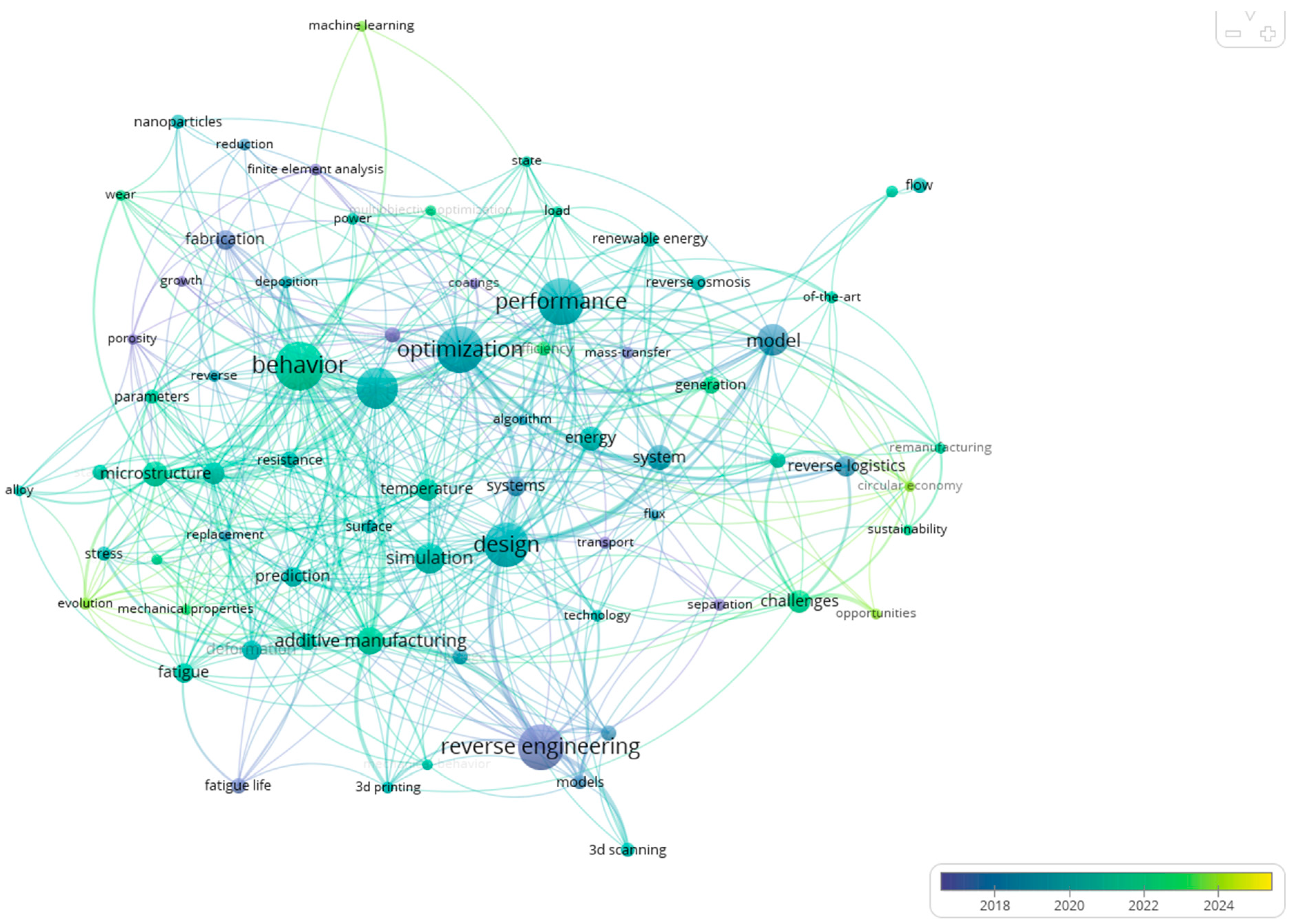
A keyword co-occurrence analysis was performed to visualize the relationships among frequently used terms across the retrieved literature. This analysis was conducted using VOSviewer software version 1.6.20 [22] which allowed the construction of a network map based on the co-occurrence strength of keywords extracted from article titles, abstracts, and author-defined keywords. In Figure 5, an overlay visualization of the co-occurrence keyword map, constructed using VOSviewer version 1.6.20, is provided. The overlay presents a visualization of keyword relationships based on their frequency of co-occurrence in the literature. An overlay color gradient with respect to average publication years is included to find out the changes in research directions over time. Larger nodes represent keywords with higher co-occurrence frequencies, while a curved line connecting them shows the strength of their co-occurrence. The color bar ranges from blue (old publications dated around 2017) to yellow (the most recent one, around 2025). For instance, the terminology “reverse engineering,” “3D scanning,” and “design” was in darker blue, indicating that it has been studied in earlier years. In contrast, keywords such as “machine learning,” “sustainability,” “flow,” and “challenges” were found to appear inside the yellow color scope, indicating a surge in importance in contemporary research. Through this overlay visualization, one can follow the path of development of this field and highlight some emerging themes, such as AI applications, optimization methods, and sustainability issues within reverse engineering and additive manufacturing. Detection of these trends will aid researchers in anchoring with existing work and possibly explore areas that are yet underperformed.
Information from each selected study was gathered based on the alignment with RQs. Data from the included studies were extracted using a structured charting form developed in Microsoft Word. The form was designed based on the RQs and applied to selected studies. Variables extracted included bibliographic details, application domain, component type, RE technique, scanning equipment, CAD reconstruction approach, internal geometry modeling, post-processing steps, use of AI/algorithms, reported challenges, and purpose of RE application. The authors charted the data from each study, and discrepancies were resolved through discussion. Where uncertainties arose, the full text was revisited to ensure accuracy. No additional data were requested from the study authors, as all necessary information was available within the published articles. Moreover, no assumptions were made about missing data; only reported information was charted. As the primary objective of this review was to map the existing literature on RE of mechanical components and synthesize technological applications, rather than evaluate the methodological quality of individual studies, no formal quality assessment for risk of bias in the included studies was conducted. The primary purpose of the review was to provide a descriptive synthesis of applications, techniques, and challenges associated with RE of mechanical components, and did not involve quantitative synthesis or calculation of statistical effect measures. After extracting information, studies were allocated to thematic synthesis categories based on the predefined RQs and extracted variables, including RE technique, application domain, scan techniques, and so on.

3. Application of RE in Mechanical Component

RE is of paramount importance for remanufacturing, repairing, and upgrading mechanical parts, particularly in situations where original design files or CAD models are unavailable. Upon reviewing the literature, it was determined that in various sectors, including automotive, aerospace, marine, and energy, the application of RE has vast potential. Researchers have employed various methodologies, including 3D scanning, CAD modeling, simulation, and a combination of additive and subtractive manufacturing techniques. Method selection often depends on the very special needs of the component and its intended purpose. A comparison of the major characteristics analyzed from the studies is provided in Table 2.

3.1. Restoration, Remanufacturing, and Redesign

A digital restoration framework based on 3D scanning, simulation, and additive manufacturing has been shown through various studies to restore damaged or worn mechanical components efficiently. Chiriță et al. [35], for example, restored a hydraulic flowmeter rotor using structured-light scanning, processed the point cloud data in SolidWorks, and rebuilt the part using Masked Stereolithography Apparatus (MSLA). The final component fit perfectly into its original assembly. Moreover, Zhu et al. [25] employed 3D scanning, laser cladding, and post-machining to restore damaged 45 steel gears. They developed an optimal scanning strategy and overlap rate to achieve higher shape accuracy and surface finish. Zhao et al. [26] adopted a similar method in restoring blades of centrifugal compressors, applying laser-based additive manufacturing coupled with five-axis CNC milling. Their outcomes maintained dimensional tolerances within 150 microns. More logical aggregations prompted other researchers to integrate the evaluation of damage with simulation into the repair and remanufacturing workflows. Huang et al. [30] developed a hybrid process combining 3D scanning, finite element analysis (FEA), and fatigue life prediction to support laser cladding repair of turbine blades. Likewise, Li et al. [33] developed an entire remanufacturing pipeline for forging dies and gear brackets, which included surface scanning, modified Iterative Closest Point (ICP) alignment processes, and rule-based decision criteria for determining the application of additive versus subtractive techniques.
However, despite these advances, numerous restoration methods still rely on manual decision-making and do not follow a common validation metric. Thus, it implies much more standardization and interoperability required if the processes are to be scaled and automated. Yilmaz et al. [42] presented a fully integrated repair system based on RE for thin, curved compressor blades in aeroengine applications. Their approach used 3D optical scanning with the GOM ATOS II 3D scanner, adaptive Non-Uniform Rational B-Splines (NURBS) surface reconstruction, and multi-axis CNC machining. This approach reduced the repair turnaround time by almost 30% while maintaining acceptable dimensional accuracy and surface quality. Another example presented by Ponticelli et al. [43] is the restoration of a damaged impeller from a submersible electric pump. The first step was to design the part completely in CAD so that it could be built precisely using the additive manufacturing technique. From initial manual measurements defining the first geometry, they continued through to building an entirely functional replacement, demonstrating the effectiveness of RE-based remanufacturing on operational components.
Along with repairing damaged parts, reverse engineering (RE) can also foster structural redesign and optimization, especially when combined with simulations and design software. Othman et al. [44] laser-scanned and modeled a Volkswagen brake caliper with Autodesk Inventor, slightly modifying it in Altair Inspire through a lattice design that led to the reduction of 36.67% of the weight of the part while complying with safety standards A parallel rationale was maintained by Freddi et al. [5], who applied high-resolution laser scanning and finite element analysis (FEA) to optimize a connecting rod for a motorcycle. They managed to reduce the weight by about 11.2% by removing material in areas of low stress. Patpatiya et al. [32] extended RE into the domain of reverse manufacturing of threaded fasteners, demonstrating not only the feasibility of PolyJet fabrication within IT06 tolerance limits but also the dependency of dimensional accuracy on resin type and orientation. Their analysis of thread pitch and depth deviations highlights how RE accuracy must be assessed at the level of functional features, since minor geometric errors directly affect assembly performance. This case also highlights the importance of standards-based dimensional validation in RE workflows, which links scanning outputs to ISO tolerance classes. Therefore, these studies suggest that RE goes beyond basic replication of components, offering chances for performance enhancement and innovation to reinterpret the original design intent. Urbanic [23] contributed to this area by developing a structured RE methodology that focuses on feature classification and the reconstruction of operations such as lofts and revolves, thereby ensuring an accurate recreation of geometry and the development of casting patterns. Osipov et al. [24] further elaborated on the design intent by creating a combustion chamber in Geomagic Design X, which was validated through comparative physical measurements. Moreover, Todorov et al. [45] presented a sustainable machining approach for aluminum alloy castings by integrating 3D scanning, reverse engineering, and virtual models, where scanned point clouds were aligned with CAD data to optimize basing, stock allowances, and CAM programming, thereby improving accuracy and reducing material waste.
Most redesign workflows, however, remain isolated case studies; therefore, a much wider application of the found methodology will require the establishment of robust guidelines for integrating RE into the fields of mechanical simulation, fatigue estimation, and downstream production planning. Spare parts often present a unique challenge when technical documentation is missing or when original components are no longer available. RE has been widely used to address this gap; however, conventional geometry-based replication does not always fully leverage the capabilities of additive manufacturing. A recent contribution by Rešetar et al. [46] addresses this by coupling reverse engineering with functional analysis and Design for Additive Manufacturing principles. In their case study of a spur gear, the part was first scanned and its functional surfaces identified to ensure compatibility. However, the redesign process went further by introducing AM-specific enhancements, such as internal cooling channels and lightweight void structures. The outcome was a spare gear that satisfied the operational requirements of the original while simultaneously improving cooling performance and reducing material usage. This shift from replication toward functional redesign highlights how reverse engineering can evolve into a knowledge-driven process that exploits AM’s design freedoms, pointing to future directions where geometry capture is only the starting point. Paryanto et al. [47] demonstrated a RE method for optimizing a train brake pad using mobile photogrammetry and AI-enhanced 3D reconstruction. The workflow involved capturing 432 images under controlled lighting, generating dense point clouds in Agisoft Metashape 2.2.1 software, and refining models in Geomagic Studio using NURBS-based surface reconstruction. The method enabled accurate parametric modeling and supported FEA-based structural optimization, ultimately reducing contact stress by 28% and von Mises stress by 34% post-optimization. Reddy et al. [48] performed a deviation analysis of a reverse-engineered freeform car fender reproduced through FDM, reporting an average deviation of ±0.78 mm with ~95% of points within a ±2 mm tolerance. Their study illustrated how noise reduction, sampling, and mesh processing steps influence fidelity, underscoring the importance of statistical evaluation (RMS error, sign test) in verifying whether RE-generated models meet engineering accuracy requirements. Spare gears are often difficult to source when documentation is missing or when production volumes do not justify mold manufacturing. Palka [49] illustrated how RE combined with FDM-based additive printing can address this gap. Using both manual caliper measurements and 3D scanning to digitize a damaged gear, the study reconstructed a CAD model in Fusion 360 and produced a functional replacement in less than an hour of print time. The approach not only restored an unavailable part but also allowed potential improvements in geometry or materials without increasing cost. Such cases highlight how RE and additive printing can function as a practical maintenance strategy, reducing downtime and aligning with Industry 4.0 objectives for on-demand part sustainment.
These studies reflect the maturity of RE-driven restoration practices, highlighting a transition from ad hoc repairs to data-driven, simulation-enhanced remanufacturing workflows. Whether through hybrid manufacturing processes, fatigue life prediction, or topology-informed redesign, RE is enabling faster, more accurate, and more intelligent recovery of mechanical components.

3.2. Modeling Internal Geometry, Simulation, and Analysis

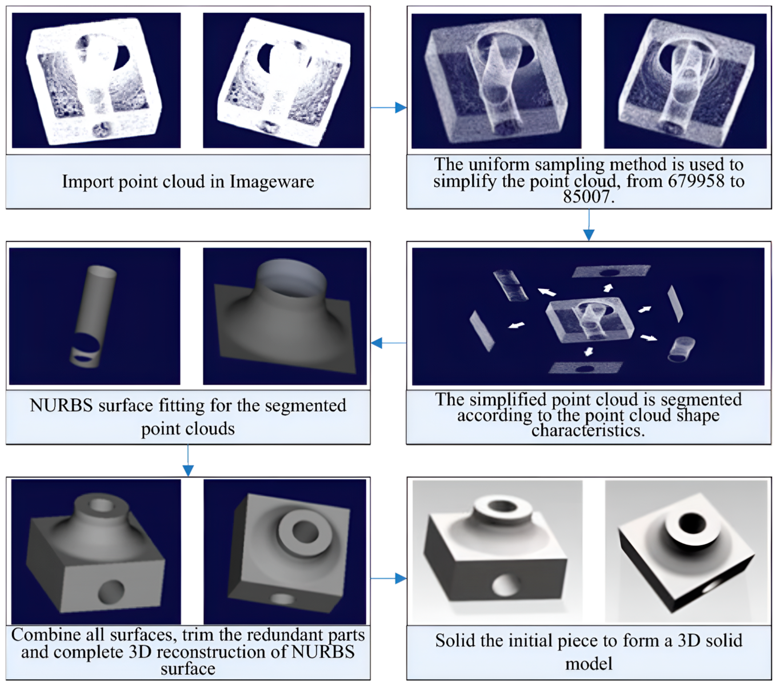
RE techniques are increasingly used to recover internal geometries and enable simulation-based evaluations of mechanical components, especially when original CAD data is unavailable. A range of studies demonstrates how combining internal and external scanning technologies, photogrammetry, and layered reconstruction methods with simulation tools can facilitate structural validation, fatigue life estimation, and wear analysis. Gameros et al. [39] introduced a multi-sensor strategy for a nickel alloy turbine blade that featured intricate external and internal geometries. Their pipeline integrated optical scanning using 3Shape Q800 of the 3Shape manufacturing company situated in Copenhagen, Denmark, for external surfaces, X-ray CT scanning for internal channels, and CMM data for reference dimensions using Zeiss METROTOM 1500 by ZEISS Group headquartered in Oberkochen, Germany. This process supported the development of a high-fidelity NURBS-based CAD model that could be used for both finite element method (FEM) analysis and additive repair applications. Rao et al. [36] discussed a framework for non-destructive internal defect assessment of aluminum components through photogrammetry combined with ultrasonic phased-array data. The study has focused on reconstructed geometries within elastic reverse time migration (ERTM) to visualize internal flaws, even when no original CAD model is available. ERTM is particularly useful for legacy or proprietary parts with untraceable design documentation. By integrating photogrammetry with simulation-based defect detection, researchers have successfully imaged features on steep or vertical surfaces that, for various reasons, cannot be easily accessed using conventional scanning methods. In a related study, Dong et al. [29] introduced a RE workflow to reconstruct internal features by cross-sectional imaging. It commenced on an industry-level precision milling machine, with layer-by-layer uniform milling and imaging of each layer with a CCD camera. Based on sub-pixel contour detection using an enhanced Canny output, they traced the contours, creating point clouds that were filtered with octree-based curvature filtering, and finally converted to 3D surfaces by NURBS fitting. NURBS surface reconstruction from point cloud data can be directly performed when the data has clear boundaries or orderly contours, whereas irregular point clouds require segmentation, local surface fitting, and splicing. The process was successfully implemented using Imageware 13.1, and the workflow is illustrated in Figure 6. The method was validated on several components, including a turbine blade, with results that matched standard machining accuracy. These works demonstrate the increasing possibilities of RE for internal structure reconstruction. However, balancing practical precision, ease of use, and ensuring part integrity during the process is yet a formidable task.
Simulation infusion into RE workflows ensures the maximization of value of the reconstructed model through performance evaluation in a realistic setting. Wang et al. [31] used NURBS-based modeling to reverse-engineer a free-form fluid pump impeller from point cloud data. The developed model was validated in ANSYS through fluid dynamics simulations, which provided insights into flow velocity and stress distribution across the impeller. Greco et al. [50] further developed an RE framework with integrated simulation, which merged B-spline surface reconstruction with isogeometric analysis (IGA) for modeling deep-drawn sheet metal parts. In this work, a B-spline mid-surface is reconstructed and converted into thickness mapping, followed by simulations based on the Kirchhoff-Love shell theory for accurate dynamic analyses. Sedlák et al. [27] utilized RE to measure wear on prototype disc milling cutters. The cutting tool and the grooved workpiece were scanned using an ATOS Compact Scan 2M optical system by ZEISS Group headquartered in Oberkochen, Germany, and the meshes generated from the scan were then aligned with CAD references. This alignment was necessary to identify variation in dimensions induced by wear. Through color-coded deviation maps, the blade profiles are then compared, allowing for some insight into the degradation of tools over time. Kašpar et al. [40] presented another simulation-integrated RE approach to estimate the fatigue life of cold-formed steel components. Through 3D scanning of the DC04 and S420MC steel specimens, volumetric meshes were created, and inverse stamping was used to compute the effective plastic strain. Fatigue life prediction was then performed utilizing Finite Element Method Fatigue (FEMFAT) 2022a software with the S-N curves. This approach provided a feasible option for fatigue analysis in circumstances in which information pertaining to the original forming process was unavailable. RE has also been employed as a verification methodology for geometrically complex components. In the study of Gabštur et al. [51], welding fixtures for cabin structures were analyzed using a Kreon ACE-7-30 scanner in combination with PolyWorks Inspector software version 2022. The approach revealed welding-induced deformations and fixture inaccuracies that traditional measurement tools often overlook. By creating color deviation maps and applying tolerance-based assessments, the methodology enabled early detection of manufacturing errors and reduced deviations to below 1 mm. This case demonstrates how RE can move beyond model reconstruction to serve as a feedback mechanism for process optimization and fixture quality assurance. Ktari and El Mansori [52] developed a RE-based methodology integrating 3D scanning, CAD reconstruction, FE simulation, and low-pressure sand casting (LPSC) for remanufacturing failed aluminum parts. The approach achieved dimensional accuracy within tolerance limits and demonstrated improved quality compared to conventional gravity casting.
The studies portray a shift in practice, where the objective of RE practice was no longer limited to geometric reconstruction but also involved establishing detailed models for structural, thermal, and even fatigue analyses. Merging high-resolution scanning, photogrammetry, and surface reconstruction with simulation tools has enabled the assessment of component performance in scenarios where original design data are missing. This application is crucial for working with outdated equipment, on critical components, and for remanufacturing tasks. There is a lack of standardized metrics to measure the quality of meshes from scanned data, which may affect the convergence of their finite elements. Additionally, there is a lack of automated workflow linking directly from scan data to simulation, which reduces the industrial scaling of such methods.

3.3. AI-Driven RE Approach

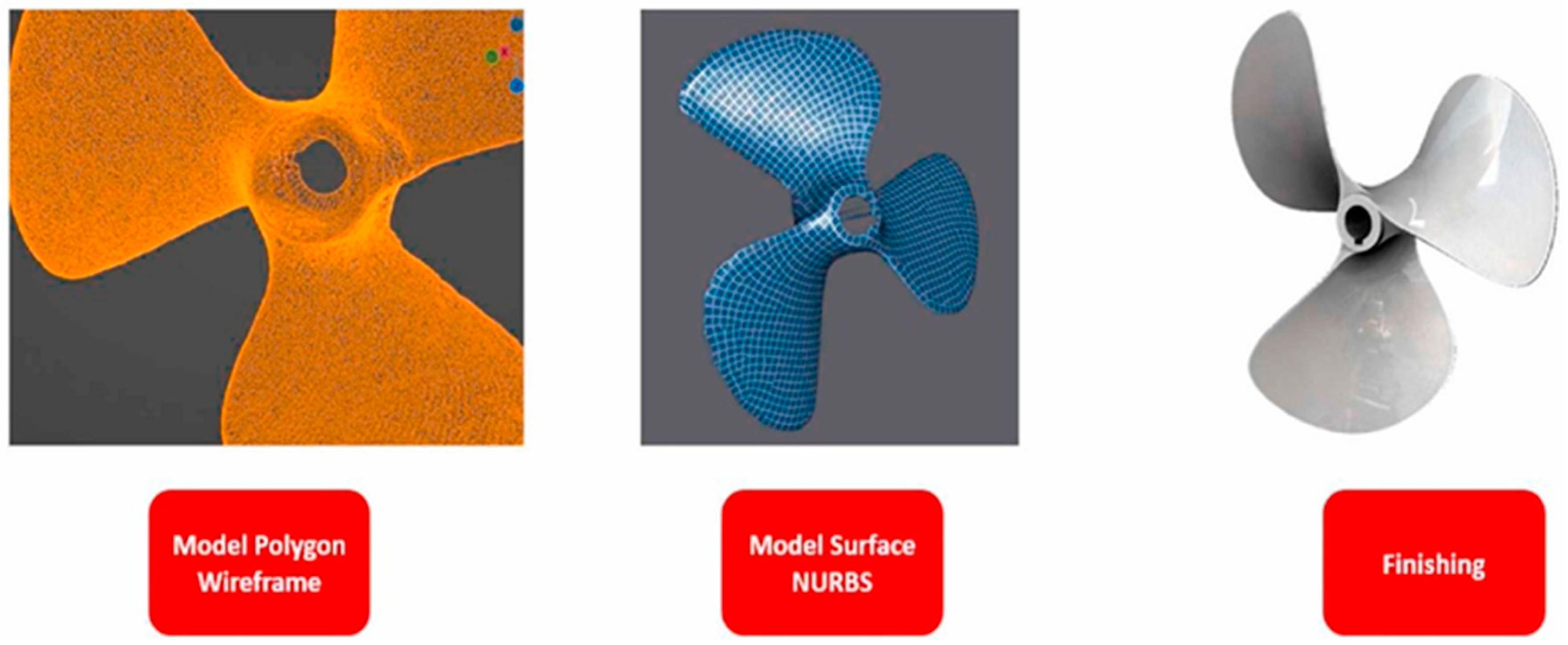
As RE continues to grow, recent studies are becoming more interested in automation, AI for cost-effective means, and better 3D reconstruction workflows. Deep learning has been increasingly adopted for 3D reconstruction, with surveys mapping out the breadth of current approaches. Samavati and Soryani [53] reviewed volumetric, surface, point-based, and multi-view methods, while also summarizing available datasets, including ShapeNet, ModelNet, and Pix3D. They emphasized recurring limitations (e.g., high computational cost, scarcity of real-world datasets, and difficulty in fine-detail reconstruction), but also pointed to future research in multimodal fusion and generative modeling. Moreover, Deep learning has recently been positioned as a transformative enabler for CAD reconstruction, with dedicated surveys highlighting the rapid progress in this area. Lin et al. [54] reviewed approaches spanning point cloud to CAD conversion, sketch-based modeling, B-rep generation, and sketch synthesis, while also mapping the landscape of datasets and metrics. They identified persistent challenges, particularly the scarcity of annotated CAD data, limited constraint handling, and weak integration with industrial toolchains. They also pointed to promising directions, such as multimodal fusion, Transformer-based models, and interactive AI-assisted design. Faizin et al. [55] thus developed an inexpensive RE method utilizing open-source and AI-assisted tools. The technique involved using platforms like Google Colab, with the integrated use of Agisoft Metashape, Blender, and Meshroom demonstrated in the reconstruction of a marine propeller blade from gathered images using photogrammetry. The generated high-resolution 3D model of a 260 mm propeller blade is shown in Figure 7. Their study highlighted that different reconstruction methods yield varying levels of accuracy, enabling the comparison of measurement results and the quantification of deviations. The approach offered a cheaper alternative to industrial-grade scanners, but even with existing technological limitations, model production lacked angular accuracy, indicating precision trade-offs.
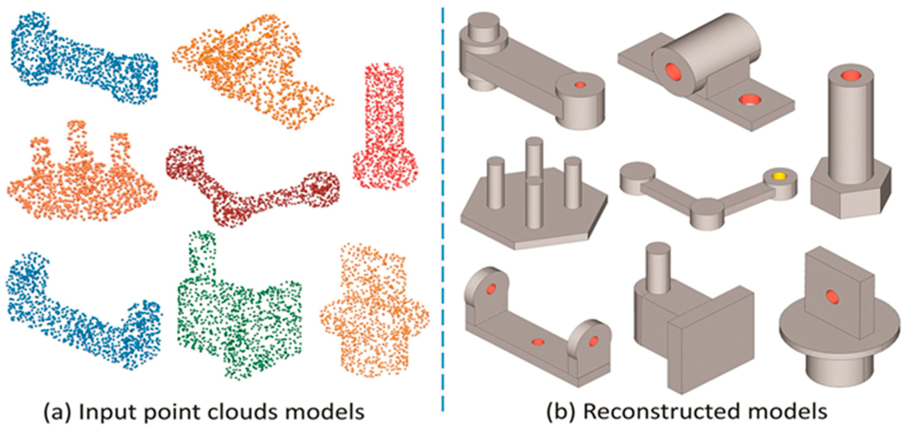
Moreover, Zhang et al. [56] proposed Brep2Seq, a deep neural network that reconstructs CAD models by predicting a parameterized sequence of modeling operations from B-rep input. Trained on a synthetic dataset of 1 million CAD models automatically generated, the method achieved over 97% valid reconstructions with high fidelity across both synthetic and real-world datasets. While Brep2Seq effectively reconstructs B-rep models, its performance is not validated on real-world scan data due to the distributional gap and lack of semantic alignment between synthetic and real models. However, the work illustrated the growing interest in democratizing RE in favor of cloud-based tools and machine vision techniques. Figure 8 illustrates the results of the reconstructed CAD model from synthetic point cloud data. Shape reconstruction in RE often assumes that point cloud data are normally distributed, an assumption that rarely holds in industrial practice. Gálvez et al. [57] explored this by modeling point clouds with alternative statistical distributions and solving the resulting nonlinear optimization problem using a simplified bat algorithm. Tested across several examples, their method achieved accurate reconstructions with low error even under noisy and irregular data conditions. This integration of industrial AI with RE highlights how metaheuristic optimization can make reconstruction more robust, pointing toward future developments in automated model selection and digital twin-oriented quality assessment. In another study, Sun et al. [34] addressed the issues of reflective surfaces that generate scan errors, such as outliers and missing data. They combined line-structured light scanning with a neural network called View-Transform-PointNet to detect outliers, and applied a grayscale-based method to repair the missing areas in the point cloud. Their technique was validated on mechanical components, such as automotive connecting rods and robotic fixtures, and the results revealed a considerable improvement in reconstruction accuracy, particularly in concave and highly reflective regions. The studies demonstrate how AI can enhance scan quality and reduce dependency on specialized equipment. However, adapting these methods to handle a wide range of surface textures and lighting conditions remains an area that needs further development. Moreover, RE is not always confined to reconstructing geometry; it can also be extended to recover material properties. Pashkov et al. [58] demonstrated this by applying machine learning to predict the mechanical and tribological performance of TiAlN multilayer coatings. Using micromechanical simulations as training data, they tested multiple algorithms and developed a tandem neural network capable of solving the inverse problem and deriving feasible layer parameters from target properties such as Young’s modulus and shear strength. The model achieved predictions with less than 5% error and was validated against nanoindentation data, showing how AI can enable property-driven RE. This expands the scope of RE toward functional material design, where geometry and performance can be reconstructed in parallel.
AI is also being applied in RE to support predictive modeling and improve the process of creating editable CAD models. For example, Sukumar et al. [28] developed a pipeline that utilized thermal simulation in conjunction with data from the IVP Ranger SC-386 laser scanner to reverse-engineer automotive parts. They aligned multi-view scans in Rapidform and validated simulated heat distributions against real-time infrared imagery using MuSES. This approach demonstrated RE’s potential for performance diagnostics beyond geometry capture. Wang et al. [37] focused on generating editable, design-intent-compatible CAD models from surface meshes. Their multi-stage framework involved denoising, geometric segmentation, and hybrid surface- and solid-based feature reconstruction, yielding models suitable for turbine blades and aircraft parts where design data was missing. Although this method enabled the recovery of parametric geometry, it was best suited to parts with regular, well-defined features. This reconstruction strategy enabled the generation of editable, reusable models suitable for industrial parts, such as turbine blades and aircraft components, particularly when original design files were unavailable. As AI integration continues, several gaps remain. To address the lack of machining-feature data in CAD reconstruction research, Lee et al. [41] created a dataset comprising over 700,000 parametric CAD models that contain features such as holes, pockets, fillets, and chamfers. They paired this with a 3D CNN encoder–decoder framework that preserved these features during voxel-based reconstruction, achieving error rates below 1% and outperforming prior baselines. Importantly, their dataset included interactive features, enabling the network to handle more realistic mechanical part configurations. However, their dataset, while extensive, is synthetically generated and therefore lacks the full complexity of industrial parts. Moreover, reconstruction was restricted to low-resolution 64 3 voxel grids due to GPU limitations, preventing the capture of fine machining details. These issues highlight two major bottlenecks in feature-aware CAD reconstruction: the need for real-world datasets and scalable algorithms that can handle higher-resolution geometric representations. Furthermore, the study demonstrates how tailored datasets and feature-aware networks can enhance AI-driven reverse engineering of functional CAD models. Deep learning is increasingly being applied to bridge raw scans and CAD-ready models. A recent example is the BRepDetNet framework, which learns to detect boundaries and junctions from 3D scans, thereby enabling Scan-to-BRep conversion as an intermediate step toward parametric CAD reconstruction [59]. Trained on large annotated datasets (CC3D, ABC), the model achieved substantially higher recall and precision compared to existing methods, owing to its novel integration of non-maximal suppression loss during training. This approach demonstrates how AI can advance RE beyond geometric replication into feature-aware CAD modeling, thereby opening up pathways for automated machining feature recognition and design history recovery. Yanamandra et al. [60] developed a RE methodology for fiber-reinforced composite parts fabricated via fused filament fabrication, combining micro-CT and SEM imaging with a recurrent neural network (RNN–LSTM) to reconstruct the 3D printing toolpath. The study achieved dimensional accuracy within 0.33% and successfully predicted fiber orientation layer by layer, highlighting the potential of AI-driven RE in reproducing both geometry and process information. This approach also highlights emerging challenges in cybersecurity and intellectual property in additive manufacturing, as the reconstruction of reinforcement distribution and toolpath poses risks of unauthorized replication. Many current approaches lack robustness when faced with highly irregular or noisy scan data. Furthermore, most AI-assisted methods are task-specific and fail to generalize across different components or scanning contexts. These limitations highlight the need for more adaptable learning frameworks and for integrating AI based reasoning to support simulation-ready RE workflows in diverse industrial environments.

3.4. Trends in 3D Scanning

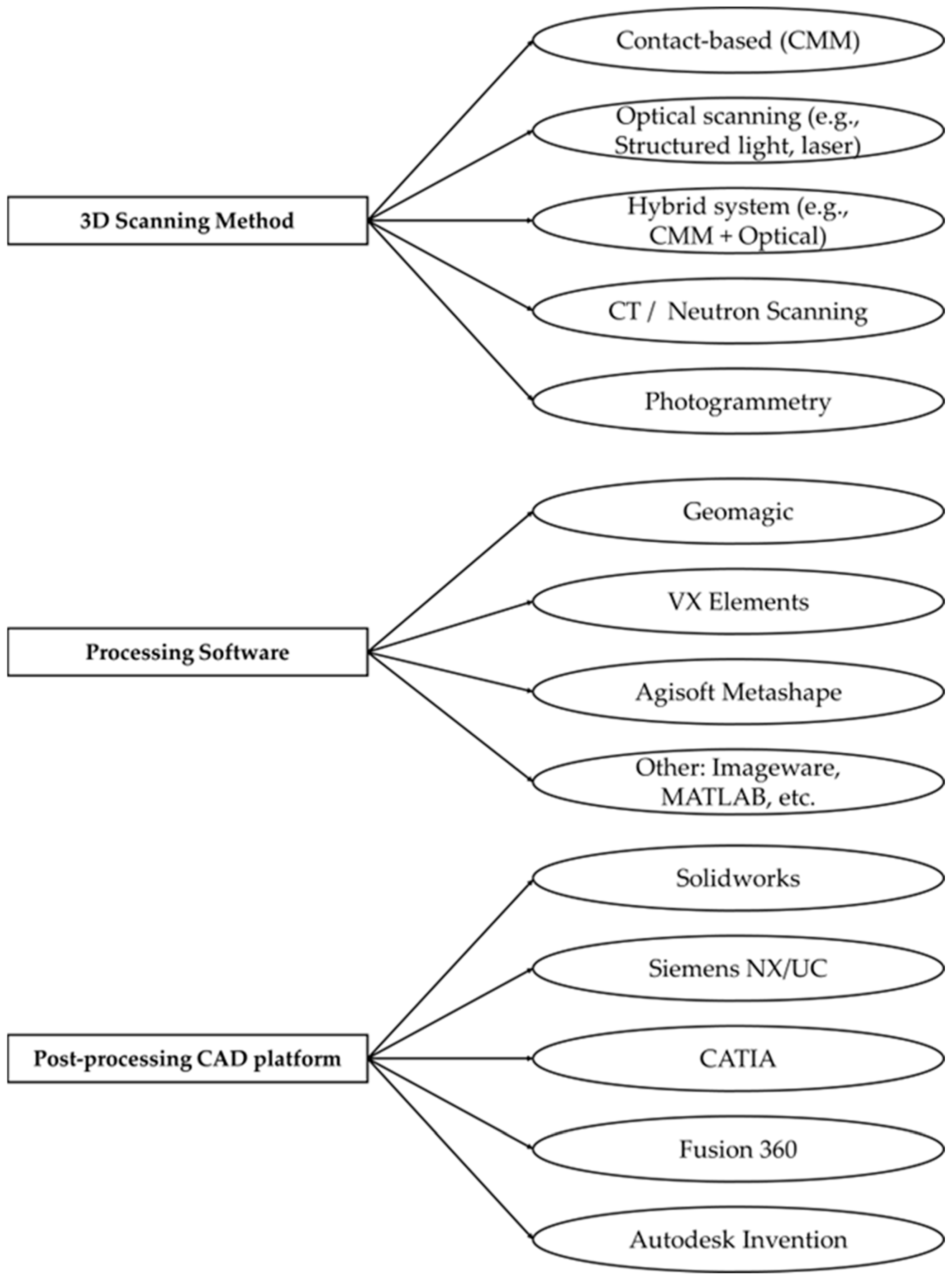
The evolution of 3D scanning technologies has played a pivotal role in advancing RE, transitioning from traditional contact-based approaches to rapid, non-contact systems. These technological advancements have greatly helped workflows in the applications of mechanical design, manufacturing, and inspection. The technology tree, highlighting 3D scanning and post-scanning technologies, is illustrated in Figure 9. Now, structured-light and laser scanners are the most useful tools in the field of RE, which have the ability to generate dense point clouds with sub-millimeter accuracies in a short amount of time [61]. Devedzic et al. [62], for example, used an Artec Spider scanner, which digitally captured surface data with an accuracy of 0.05 mm and a resolution of 0.1 mm at a speed of up to one million points per second. Such features enable it to scan and capture data from sharp edges and intricately detailed surfaces at very close distances. Other optical scanners, including the OKIO-B [25] and the Shining 3D FreeScan UE Pro [24], have proven effective in digitalizing worn components for repair and remanufacturing. While often favoring non-contact scanning methods for speed, flexibility, and ease of use, contact-based measurement systems, such as coordinate measuring machines (CMMs), are very useful for components that require extreme precision. According to Šagi et al. [63], high-end CMMs can achieve an accuracy of approximately 1–2 μm, making them suitable for applications that require tight dimensional tolerances. Nevertheless, their slower assessment speed and difficulty in capturing complex geometries are drawbacks. This limitation has led to a growing interest in the hybrid measurement systems that combine the accuracy of CMMs with the speed and flexibility of optical scanning. This combination has increased the importance in modern engineering applications, particularly in terms of accuracy and efficiency. Three-dimensional scanning has also been utilized to support reverse manufacturing, where both replication and redesign are necessary. Chaudhary and Govil [64] presented a case in which a two-blade RC propeller was scanned, digitally modified into a three-blade design, and reproduced through FDM printing. The workflow not only reduced dependency on expensive molds, making small-batch production viable, but also enabled rapid customization. Inspection carried out with the same scanner confirmed dimensional accuracy comparable to a CMM, while offering faster setup, portability, and ease of use, reinforcing the role of scanners as practical tools for Industry 4.0–driven RE applications.
Advanced application-specific modalities have been incorporated into the expanding range of 3D scanning technology applications. Although not widely used, tomography and neutron-based techniques have provided useful access to internal geometry reconstruction, especially in parts that do not offer easy access or have complex internal configurations. Roos et al. [65], for instance, used neutron CAT scanning to model internal features of gas turbine components. Photogrammetry, traditionally considered a low-fidelity option, has gained renewed attention with the integration of AI. Baroiu et al. [66] demonstrated the use of RE for redesigning and inspecting helical pump screws in the absence of design documentation, employing ATOS Core scanning and GOM Inspect to compare scanned and CAD models. Their study highlights RE as a practical solution for sustaining industrial components by enabling the accurate reproduction of spare parts and validating functionality through deviation analysis. The use of ATOS Core optical scanning with point cloud polygonalization provides a concrete example of how contactless scanning enables the fast and precise reconstruction of complex geometries. Moreover, Faizin et al. [55] presented a low-cost RE setup using a Sony A6000 mirrorless camera, Sony Corporation, Tokyo, Japan, Meshroom based on the AliceVision framework, and Blender, highlighting the democratization of scanning tools for resource-constrained users. Despite trade-offs in precision, such workflows demonstrate increasing accessibility in RE. Similarly, Sukumar et al. [28] combined laser scanning with thermal imaging to validate temperature distributions in exhaust components, signaling the growing integration of scanning with simulation. Buonamici et al. [17] further highlighted software trends, showing that platforms like Geomagic Design X outperform general-purpose CAD software (e.g., Siemens NX-R) in mesh segmentation, especially for freeform geometries. Although mainstream CAD tools such as CATIA, Siemens NX, and Fusion 360 now support mesh input, they often fall short in detailed mesh editing. Beyond laser or structured light scanning, vision-based methods have also been explored for RE. Huo and Yu [67] presented a stereo vision system that reconstructs 3D models of mechanical parts directly from 2D images. Their workflow integrated grayscale preprocessing, camera calibration, stereo matching, and triangulation to generate point clouds and CAD-ready models, validated through the reconstruction of a gear. While the method achieved high positional accuracy, it remained sensitive to illumination, calibration errors, and noise, underscoring both the promise and current limitations of image-based 3D reconstruction.
Recent developments have also extended scanning approaches to LiDAR–camera fusion and consumer-grade LiDAR sensors. Li et al. [68] developed a low-cost prototype that fused 2D LiDAR depth data with RGB images from a consumer digital camera, achieving textured 3D indoor reconstructions through checkerboard-based extrinsic calibration and RANSAC alignment. This system demonstrated that camera–LiDAR integration can provide accurate colorized point clouds at a fraction of the cost of 3D LiDAR systems. Similarly, Vogt et al. [69] evaluated Apple’s iPad Pro LiDAR and TrueDepth sensors against an industrial scanner, showing that while industrial systems remain more precise, consumer devices can achieve sub-millimeter accuracy sufficient for certain reverse engineering tasks and low-cost mass customization. Broader reviews of LiDAR mechanisms [70] indicate that MEMS- and solid-state-based systems are increasingly promising, offering advantages in robustness, scalability, and reduced size/weight compared to traditional opto-mechanical setups.
Table 3 presents the comparison between the scanning technologies and post-processing tools used across studies, showing a trend toward hybrid pipelines that integrate scanning, mesh cleaning, and export to simulation-ready CAD platforms. While optical scanning (e.g., HandySCAN, Freescan, OptimScan) remains dominant, workflows increasingly combine multiple data acquisition sources with specialized mesh processing tools such as VX Elements, Geomagic, and Agisoft Metashape. Post-processing often includes conversion to editable CAD formats via SolidWorks, Siemens NX, CATIA, or Fusion 360, enabling integration with downstream applications such as simulation, manufacturing, or structural optimization.
Despite their methodological differences, these approaches share a common objective: generating accurate, editable, and functional digital replicas of physical components. As scanning technologies continue to advance, the convergence of hardware capabilities, specialized software platforms, and AI-driven automation is set to accelerate RE workflows. This advancement is likely to evolve RE in such a manner that, in the near future, it will not only become faster and easier to access but also much more intelligent, specifically in dealing with damaged and geometrically complex mechanical parts.

4. Challenges of RE in Mechanical Parts

The reliability of mechanical components is specifically challenging in critical industries like aerospace, automotive, and energy for several reasons. These challenges arise from the complexity of parts, which includes the consideration of complicated geometries, tight tolerances, hidden or inaccessible internal features, and variable properties of material, and also from an external perspective by including constraints on access to suitable tools, limitations of software, and the lack of technical skills among the personnel involved. This section provides structured insights into the major challenges reported in the literature.

4.1. Product Complexity, Internal Geometry, and Physical Barriers

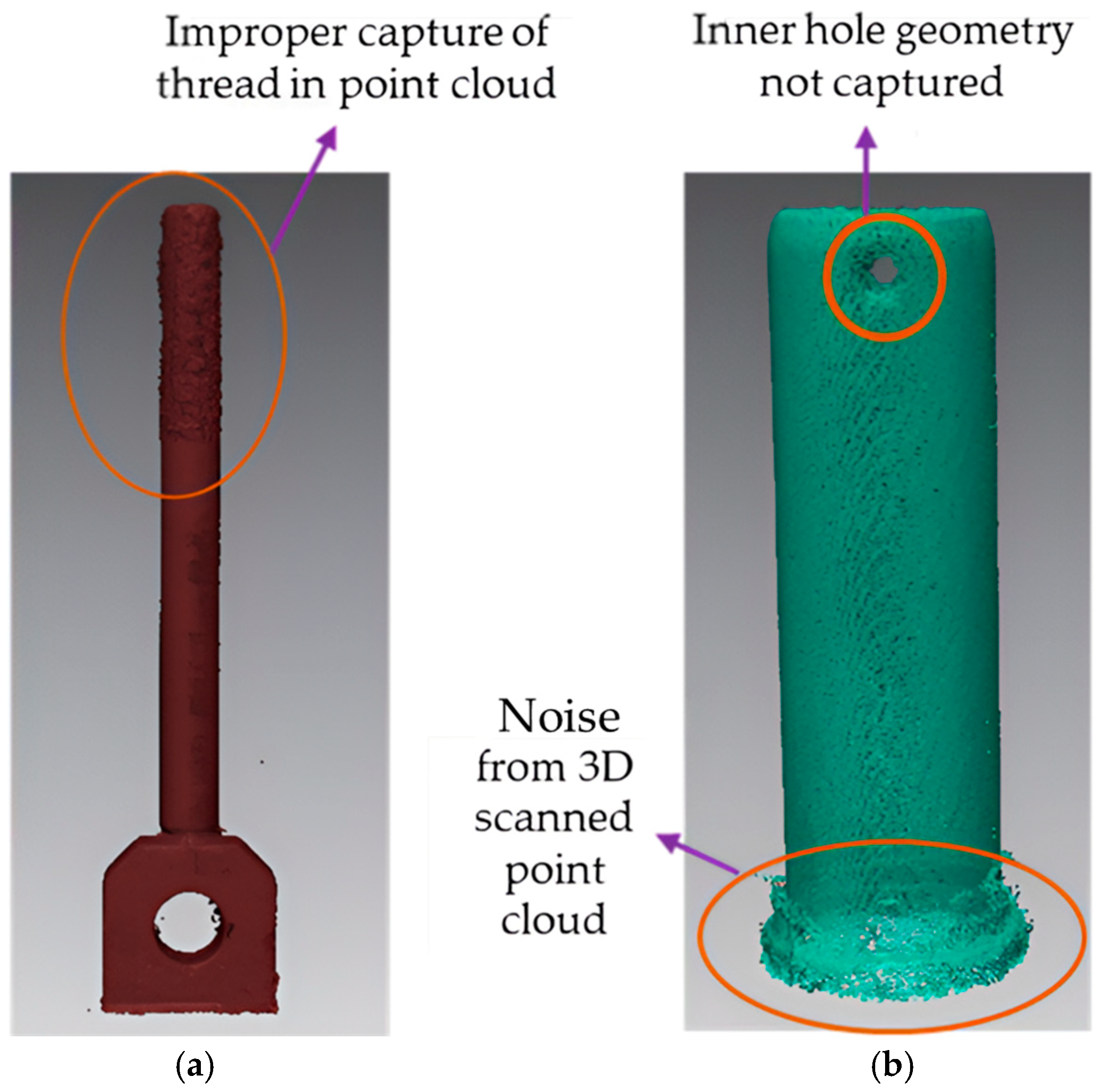
Many challenges in RE stem from the intrinsic physical and design complexity of mechanical components. Curtis et al. [19] classified RE challenges into two primary domains: internal barriers, which are tied to product-specific characteristics such as freeform surfaces, inaccessible geometries, and multi-material construction, and external barriers, including tooling constraints, environmental conditions, and human resource limitations. Their analysis highlighted three core domains that influence RE outcomes: the technical complexity of the product, the availability of resources, and the expertise of the engineering team. In practice, the lack of precision tools (e.g., micrometers, gages, coordinate measuring machines, optical scanners, and scanning electron microscopes) as well as specialized software, such as CAD/CAE platforms and orientation image microscopy (OIM) tools, further limited the ability to extract and process essential information accurately. The authors emphasized that successful RE not only requires technical proficiency with hardware and software but also a multidisciplinary knowledge base. For example, RE of energy storage components might require an understanding of chemistry in addition to design reconstruction techniques. Moreover, a major challenge when scanning dense materials lies in the scanner’s inability to capture fine details such as threads, sharp edges, or the full depth of holes, as the material’s high density can interfere with laser or light penetration; however, these limitations are typically overcome during the post-processing stage, where advanced point cloud reconstruction techniques help recover and refine the missing or distorted features to produce an accurate digital representation [79]. Figure 10 illustrates the issue observed in the 3D scan of a component, where the thread features are not properly captured, and the hole geometry is inadequately represented using Faroarm® 3D laser scanner (Headquartered in Lake Mary, Florida, United States). After machining, both metal and non-metal parts often exhibit complex surface reflection behaviors, including regions of diffuse and specular reflection. Figure 11 illustrates the presence of specular reflection artifacts on the surface, as observed in the 3D scan of the component using Faroarm® 3D scanner (Headquartered in Lake Mary, Florida, United States).
Moreover, Harston and Mattson [80] elaborated on how RE complexity is magnified by the internal technical makeup of the product, which includes the type and quantity of embedded information, as well as the interactions between subsystems. Products are sometimes intentionally designed to obscure internal structures, thereby deterring RE through increased technical opacity. The challenge of data extraction depends on the nature of the data itself, whether geometric, material, or chemical. Localized treatments such as heat-affected zones may introduce material heterogeneity that is difficult to detect using standard scanning techniques. Moreover, embedded sensors or microstructures may not be apparent until disassembly, adding to the time and effort required for reconstruction. Rochefort-Beaudoin et al. [81] identified limitations in using deep learning-based methods, particularly the YOLOv8-TO model, for reconstructing topology-optimized components. Their study highlighted issues such as sensitivity to non-max suppression thresholds and a lack of curved geometries in the training dataset, which hindered the model’s ability to handle nonlinear features or complex contours. One major challenge was converting the results of density-based optimization into formats suitable for CAD, particularly in the case of thick structural components, where available training data often fell short.
The capture of internal geometries remains of prime importance for various RE scenarios, particularly when dealing with mixed materials or parts that have inaccessible inner areas. Roos et al. [65] noted several challenges, including voxel triangulation, datum plane establishment, and achieving consistent resolution, during the application of neutron tomography for turbine blade analysis. It is a challenge to extract features when the attenuation properties of the materials differ, particularly in assemblies that comprise aluminum and steel. In the work of Dong et al. [29], additional issues were related to cross-sectional milling and imaging methods. Image noise, surface machining distortion, and considerable errors in identifying curved or high-aspect-ratio features are highlighted as significant issues. Reconstruction errors were noted at arc-shapes and regions of high curvature. Similarly, Deja et al. [77] reported difficulties in scanning marine components with freeform geometry, such as mesh discontinuities and noise from surface reflectivity. They undertook extensive postprocessing using Geomagic, which included hole filling and re-meshing to address these issues. However, there were still deviations in the final models of up to 7.66 mm due to asymmetries in the manual manufacturing process. These studies highlight some of the difficulties in extracting and building upon complex features, compounded by hardware resolution limits, limited access to internal surfaces, and inconsistencies in the quality of the training datasets.

4.2. Tolerance, Dimensional Accuracy, and Error Propagation

The replication of components for remanufacturing or replacement poses significant challenges in maintaining dimensional accuracy and tolerance. Minor deviations in surface data, point cloud generation, or reconstruction algorithms can be magnified in the RE-to-manufacturing pipeline, resulting in functional mismatches at the end. Paryanto et al. [47] further note that even though photogrammetry was carried out at high resolution and AI was used in the reconstruction, some dimensional discrepancies still remained between virtual models and physical CMM measurements (up to 0.30 mm (Metashape) and 0.46 mm (AI). The dimensional accuracy of the final 3D-printed model was a critical concern, especially given the tolerances required for pump functionality. The Selective Laser Melting (SLM) process, as adopted by Ponticelli et al. [43] after CAD model reconstruction, successfully produced blade geometries with a deviation of ±0.1 mm, consistent with design expectations. Although the total dimensional error in some regions reached about 0.3 mm, the blade geometry still met functional requirements. Factors such as lighting, reflective surfaces, and limited overlap contributed to error propagation, particularly in complex geometries, such as brake pad corners and slots. Geng and Bidanda [6] discussed the cumulative propagation of dimensional errors through each phase of RE-driven remanufacturing as illustrated in Figure 12. For instance, a product designed to precision with a tolerance of P ± σ   m m encounters errors in the original manufacturing of the part, resulting in a dimensional measurement of P ± σ m   m m , where P stands for original mean dimension, σ stands for original accepted tolerance level, σ m stands for deviations induced during the actual product fabrication process. Moreover, when the RE procedure is introduced, the scanning process introduces a variation of ± σ p c during point cloud generation of the part for capturing surface geometry, resulting in a variation of P ± σ m ± σ p c   m m . As the RE procedure moves forward, the point cloud data to CAD model reconstruction introduces more variation of ± σ R E in the design process, resulting in a variation of P ± σ m ± σ p c ± σ R E   m m . Subsequent remanufacturing introduces another error, σ r e m , resulting in a final variation of P ± σ m ± σ p c ± σ R E ± σ r e m   m m rendering the reproduced product could be unfit due to exceeding the design requirements of A ± σ mm [6].
To mitigate tolerance-related issues, several methodologies have been proposed. For example, Kaisarlis et al. [82] proposed a three-step approach that combines mathematical modeling, tolerance zone qualification, and rule-based filtering to assign position tolerances in the reverse engineering of fixed fastener assemblies with limited reference data. Using measurements obtained via a CMM, their MATLAB and Excel-based implementation reduced tolerance assignment time to just 18 min and produced experimentally validated alignment results, confirming both accuracy and efficiency. Jamshidi et al. [83] proposed a tolerance approximation method by linking surface roughness with original machining processes. Using a conversion table based on ISO 8062 [84] and ANSI Y14.5M standards [85], their method estimated tolerance values from measured roughness, incorporating correction ratios to account for wear and defects. The technique avoided measuring worn regions directly and achieved estimated tolerances within 30% of actual values. While promising, the 30% margin of error poses limitations in high-precision applications where tighter tolerances are essential. In aerospace systems and precision mechanical assemblies, even slight variations in geometry can significantly impact reliability and fit. Moreover, Yilmaz et al. [42] reported key tolerance-related challenges while restoring thin-section aeroengine blades. Their method segmented reconstructed blade tips into four NURBS patches (leading/trailing edges and suction/pressure sides), where ensuring G1 continuity (smooth tangent flow) and G2 continuity (curvature consistency) between patches was difficult. Thin blade edges with small radii were especially prone to convex gouging during machining. Addressing this required adjusting scallop height, machining tolerance, and cutter contact (CC) point density, which increased the toolpath complexity and NC file size. Forslund et al. [86] noted that geometric variation must be addressed early in product development due to its influence on downstream reliability and system integration. However, in practice, this evaluation becomes increasingly difficult in complex, multidisciplinary designs. Greco et al. [50] noted that the accuracy of the surface fitting process is sensitive to scanner noise, sparse point distributions, and the tuning of fairing parameters. Irregularities and oscillations in the fitted surfaces are common if the point cloud is poorly conditioned, requiring iterative fairing and parameter tuning to stabilize the fitting process.

4.3. Scanning Limitations and Data Acquisition Challenges

Although 3D scanning technology has advanced significantly, several persistent challenges continue to affect its application in the RE of mechanical components. Many of these difficulties stem from the inherent limitations of scanning devices, the environmental conditions under which scans are performed, and the complexity of subsequent data processing steps. Some of the common problems identified by Helle and Lemu [73] include noise in the point cloud, misaligned points, outliers, and point sampling errors. These problems most often lead to the improper reconstruction of CAD models, as reflective surfaces and inaccessible areas are usually scanned incompletely and distorted. Additionally, the choice of modeling technique after scanning has a direct impact on the reconstruction quality. Primitive-based modeling tends to be susceptible to alignment errors, while NURBS modeling, although more effective in capturing detailed surface geometry, struggles when internal features are not directly accessible to the scanner. Other sources of inaccuracy include poor calibration, thermal drift, and inconsistencies in how scanning software interprets the acquired data. Šagi et al. [63] reported that optical scanners often encounter difficulties with transparent, glossy, or light-refracting surfaces. Similarly, Dúbravčík and Kender [87] found that laser scatter from shiny anodized aluminum interfered with scan quality around gear teeth. To mitigate similar issues, Pang and Fard [72] applied a matte PlastiDip coating to reflective bell crank parts, which improved scan fidelity.
The earlier study by Raja [7] also noted limitations in scanning reflective or parallel surfaces, despite significant improvements in non-contact scanners. Proper calibration and a stable scanning environment are often required to achieve reliable scan outcomes. Tóth and Živčák [88] recommended that calibration on the boards be performed from multiple angles and at varying distances as a verification of scanner accuracy. Environmental conditions, such as lighting, temperature, and humidity, need to be effectively controlled to prevent errors or data loss, as stated by 3 Space [89]. Therefore, working on components with intricate shapes under unstable conditions or poor lighting would obviously make scanning more difficult. Both Bugeja et al. [90] and Alba et al. [91] stated that poor data quality may arise from outdoor scans or from scans in low-light conditions due to ambient interference. Also, Buonamici et al. [74] noted that applying optimization algorithms (e.g., Particle Swarm Optimization) for dense mesh data required significant computational effort. Furthermore, manual segmentation, preparation of CAD templates, and data exchange between platforms such as MATLAB and Siemens NX contribute to workflow delays. Another commonly encountered issue is converting STL files into editable parametric CAD models. According to Yahaya et al. [74], internal cavities, curved surfaces, and missing features present complications in the processing of modeling. Manual interventions such as patching or extrusion would be required in such cases. These results therefore suggest that data acquisition and post-processing are very time-consuming and are largely influenced by the geometry, surface characteristics, and environmental conditions of the parts.

4.4. Process Integration, Post-Processing Challenges

RE challenges extend far beyond the initial phase of data acquisition. Bridging the gap between scanning, CAD modeling, and final manufacturing remains among the most persistent challenges. Multiple studies have outlined issues within these steps, including model reconstruction errors, model alignment, surface fitting, and software compatibility. These issues often impact the precision and efficiency of the resulting digital models and physical components. According to López and Vila [10], a problem exists in workflows connecting RE with additive manufacturing. Their analysis revealed a lack of a standardized method for converting point cloud data to usable CAD models, an arbitrary choice of materials and production processes, and a dependence on manual corrections to address scan defects. Engineers often face uncertainty in determining whether to replicate a part in its exact configuration or redesign it for improved performance. Such a decision usually requires domain-specific knowledge and a clear understanding of the original design perspective. Urbanic [23] highlighted that surface-detail-oriented workflows would create visually accurate models but may fail to maintain geometric relationships (e.g., concentricity or perpendicularity). This becomes a critical issue in worn or damaged components. Therefore, a CAD model may be very close to the scanned surface but may not preserve the original design intent important for manufacturability and functionality.
The preparation of parts for remanufacturing is also associated with several challenges. Scanning became a challenge due to corroded or eroded surfaces that were exposed during contaminant or hidden feature detection through a pre-machining operation, as stated by Zhang et al. [76]. The authors asserted that the need for a pre-repair heat treatment was significant since failure could occur even if geometric accuracy was restored if the material properties (e.g., hardness) were not properly recovered. Huang et al. [30] mentioned that these challenges further included fatigue crack, residual stresses, and thermal deformation, factors that distorted the scan data and required repeated curve fitting and point cloud alignment for an acceptable result. Zhu et al. [25] encountered post-processing issues, including powder build-up, incorrect vertical layering, and tool path deviations, while working with laser cladding. These problems resulted in deformations of the cladding track, which were then corrected through additional machining processes. Freddi et al. [5] observed that reflections and vibrations during scanning introduced mesh data errors; therefore, multiple passes of scanning and adjustments in lighting were often necessary to produce consistent results. They also faced difficulties extracting functionally significant dimensions from raw scan data. In this manner, Osipov et al. [24] addressed issues of resolution and calibration during the scanning of the combustion chamber. The detection of markers, alignment of scanning, and brightness calibration created such problems for them. The limitation of the scanner system’s resolution, at around 10.8 million points, has resulted in gaps in the early mesh, necessitating several scans and iterative corrections. Furthermore, deviations between the digital models and their physical counterparts caused by thermal deformation and partial scans had to be refined iteratively down to an error of ±3.92 mm. Chiriță et al. [35] faced similar challenges in aligning scans taken from different angles, concluding that matte spray coating and UV post-curing must be applied after MSLA printing to ensure dimensional accuracy of parts. These instances lead to the conclusion that even after obtaining high-quality scan data, the later phases of mesh cleanup, conversion of STL files to CAD, and model preparation for manufacturing could present new problems. Coordinated efforts of experts, multiple rounds of corrections, and strong coordination among the software tools, hardware systems, and processes involved will be necessary to resolve these problems. Most RE pipelines still produce static B-Rep models that lack editability and limit downstream use. To address this, Shah et al. [92] proposed a computer-assisted framework that reconstructs editable CAD assemblies directly from point clouds. Their method supports scans of assemblies without disassembly, uses simulated annealing to fit parametric sketches and features, and preserves design constraints such as parallelism and concentricity. Demonstrations on a Wankel engine and a hydraulic actuator showed that the approach outperformed commercial tools by delivering editable, feature-based CAD models rather than frozen geometry. This shift toward assembly level, editable reconstruction points to a future where RE supports digital twins and the recovery of design intent.

4.5. Human, Material, and Process-Specific Limitations

Although RE relies heavily on digital tools, the success of RE also depends on human expertise and knowledge of materials and components. Many studies have highlighted that RE cannot be successfully achieved solely by access to advanced technology; there are equally important concerns about skilled practitioners, extensive domain knowledge, and an understanding of how components were intended to be designed and actually used. Curtis et al. [19] and Šagi et al. [63] also emphasized the multidisciplinary aspect of RE, pointing out that engineers need to be familiar with core concepts in physics, materials science, and mechanical engineering. The area of expertise required varies depending on the nature of the component being assessed. For instance, analyzing a battery would require knowledge of chemistry, whereas assessing structural components would consider fatigue behavior, residual stress, and mechanical loading conditions. Wang [93] and Šagi et al. [63] stressed that the validation of material properties is crucial. Engineers should ideally be able to assess attributes such as tensile strength, thermal resistivity, and microstructural content, all of which are critical to the performance of any part. It is essential to ensure that these properties are preserved in the reproduced component for safety-critical applications. Otherwise, a geometrically precise and conforming replica of the component may fail during operation. According to Sukumar et al. [28], thermal modeling brings in additional complexity to RE workflows. Their study for the automotive industry required not only precise scanned data but also detailed input constants, such as surface emissivity and boundary conditions, before meaningful simulations could be carried out. They addressed issues of scan occlusions and large mesh sizes, which resulted in slow processing and complicated the comparison of performance with simulation results. These challenges justify the need for technical expertise combined with strong analytical reasoning.
The absence of original design drawings or specifications can increase the complexity of RE projects. Afeez et al. [78] presented a case study wherein engineers were engaged in the redesign of a crane cabin for ergonomic improvements, with a focus on reducing noise and water leakage, as well as increasing visibility. The design aspects had to consider manufacturability despite the complete absence of any digital design records. This case showed how RE not only requires modeling skills but also creative thinking and practical design experience. Understanding user requirements, managing assembly constraints, and accounting for functional tolerances under conditions of uncertainty are key to achieving a successful outcome. Pourmostaghimi et al. [94] highlighted an issue during their work with helical gears, wherein it was not possible to measure directly essential parameters such as the module and helix angles. The laser beam was indeed scattered due to the reflective nature of the gear surfaces, thus making the scanning difficult and data accuracy poor. Optimization algorithms, such as Particle Swarm Optimization (PSO), Genetic Algorithm (GA), and Grey Wolf Optimizer (GWO), were utilized for parameter estimation; however, the results showed high sensitivity to input data quality. Othman et al. [44] encountered similar limitations while reconstructing a brake caliper with lattice structures. STL-to-CAD conversion introduced mesh distortion, and surface reflectivity demanded advanced scanning techniques. Gameros et al. [39] found that optical scans achieved acceptable tolerances on turbine blades, but CT scans of Inconel interiors were degraded by beam hardening and scatter, leading to uncertainty levels more than twice those of optical scans. Li et al. [33] reported that full point clouds from worn parts reduced registration accuracy in standard ICP methods. Their improved ICP algorithm used Gaussian curvature for better alignment, but still required manual recognition of usable versus damaged geometry. Kašpar et al. [40] added that fatigue predictions in RE-modeled steel parts were affected by springback and coating effects, which distorted surface conditions and skewed life estimates. Collectively, these findings reinforce that successful RE demands more than high-resolution scanning; it also requires human insight, process knowledge, and careful integration of physical, material, and functional considerations.
A summary of key challenges and corresponding solutions identified across the reviewed studies is presented in Table 4.

5. Future Research Directions

As RE continues to evolve, several promising research avenues have been identified to address current limitations and support the next generation of digital reconstruction workflows. Geng and Bidanda [6] emphasized the need to improve automation in converting physical objects into digital models and integrating these with manufacturing systems. They highlighted opportunities to enhance sensor accuracy and algorithmic interpretation, which remain critical for increasing efficiency and reducing human dependency in RE pipelines. Moreover, Ponticelli et al. [43] emphasized the need for real-world validation under operational conditions. Although the component satisfied geometric and mechanical requirements, its actual performance during operation has not yet been validated. This gap highlights a promising area for future research. One key opportunity lies in advancing AI-driven reconstruction models. Rochefort-Beaudoin et al. [81] suggested increasing the generalizability of the YOLOv8-TO model by including curved and volumetric parts in the training dataset, tuning the model parameters, and integrating the workflow with CAD and FEA platforms. Future research should expand on this to develop domain-adaptive deep learning models that directly process reflective, occluded, or partially degraded surfaces. The improved reliability of RE for such complex applications may also require increasing the training datasets with high-curvature geometries and components made of multiple materials. While the method of reconstruction as described by Yilmaz et al. [42] was efficient, it still involved semi-manual procedures for segmentation and surface fitting. This leaves research gaps for AI-assisted approaches to surface reconstruction, such as automatic patch generation based on curvature or detection through predictive modeling to avoid gouging or distortion post-machining. More benefits could arise from real-time feedback during the manufacturing process itself, allowing for adaptive toolpath adjustments, especially when dealing with free-form geometries or legacy components that may have no known tolerances. Paryanto et al. [47] observed further improvements in accuracy through the combination of AI methods with photogrammetry. AI-based modeling reduced the time required to create digital models and produced the part with slightly larger error margins compared to traditional techniques. Possible future work could address this limitation by developing systems that integrate real-time AI correction, automatic feature detection, enhance dimensional accuracy, and minimize manual intervention during data processing.
Addressing surface-related challenges in 3D scanning remains an important direction for future research. Zhao et al. [26] and Sun et al. [34] identified recurring issues when scanning reflective surfaces, managing noise in the data, and capturing complex curvatures. Their studies point to the need for more adaptive preprocessing techniques. These may include intelligent noise filtering, curvature-aware hole filling, and machine learning–assisted alignment correction. Incorporating such methods with physics-informed models could further enhance point cloud accuracy, particularly under suboptimal scanning conditions. Internal geometry reconstruction also continues to pose a significant challenge. Roos et al. [65] and Gameros et al. [39] examined the limitations of advanced imaging methods, including neutron tomography and CT scanning. These techniques are often less effective when applied to parts with high material density or multiple material layers. Future improvements will likely depend on better scan calibration, artifact reduction (e.g., minimizing beam hardening) and the development of uncertainty quantification methods for internal feature reconstruction. An additional area of promise involves integrating CT data with external surface scans. By combining internal and external information, researchers can produce more complete and accurate models of geometrically complex components.
Yet, one important direction for future research is to address the surface-related issues associated with 3D scanning. Li et al. [33] and Wang et al. [37] emphasized the importance of registration for ensuring accuracy and model reliability when dealing with occlusion, distortion, or missing data in the geometry. Future work could focus on hybrid registration methods that include geometric descriptors, statistical modeling, and features learned through machine learning. Such methods would be particularly useful in applied fields, such as repair or remanufacturing, where scanning conditions are often far from optimal. In addition to registration improvements, integrating RE with functional simulation and validation workflows presents further opportunities. Othman et al. [44] proposed the experimental validation of lattice-integrated brake components and highlighted the need to optimize lattice generation algorithms. Therefore, future studies could develop simulation-ready CAD pipelines that accurately capture mechanical, thermal, or fatigue behavior. Such pipelines with traceability from scan to model to final part would provide a basis for reliably predicting performance. Coupling digital twins with physical testing would support real-time model refinement and performance-based design evaluation. Moreover, Greco et al. [50] recommended exploring more complex geometries using multi-patch B-splines, splines on unstructured meshes, or smooth polar splines for future research. These advanced geometrical representations could improve surface accuracy and simulation robustness in more complex RE applications.
Several studies also underscore the importance of improving RE-to-manufacturing transitions. Zhu et al. [25], Huang et al. [30], and Osipov et al. [24] discussed issues in post-processing, including toolpath distortion, surface finishing, and printing alignment. RE challenges tied to human judgment, material behavior, and legacy systems remain open areas of inquiry. Afeez et al. [78], Pourmostaghimi et al. [94], and Kašpar et al. [40] revealed that effective RE in the absence of design records, or in components affected by springback or surface coating, requires not only geometric reconstruction but also contextual understanding. Future research should prioritize the development of knowledge-guided RE systems, where expert rules, simulation insights, and historical data can guide reconstruction decisions for functionally complex parts. Additionally, there is a notable lack of fully automated pipelines for converting raw scan data into boundary representation (B-rep) CAD models. Developing such end-to-end procedures, capable of accurately translating point clouds into editable, feature-based CAD entities, would significantly reduce manual intervention, improve design intent preservation, and accelerate the integration of RE outputs into downstream design and manufacturing systems.

6. Conclusions

This review critically examined the current landscape of RE practices applied to mechanical components, with a particular emphasis on aerospace, automotive, and high-precision industrial contexts. The findings indicate that despite considerable advancements in scanning hardware, CAD modeling tools, and algorithmic techniques, significant challenges persist across multiple stages of the RE workflow. These include, but are not limited to, limitations in data acquisition for reflective or occluded geometries, inaccuracies introduced during mesh reconstruction and STL-to-CAD conversion, and interoperability issues across RE-to-manufacturing systems.
The analysis further revealed that RE remains a knowledge-intensive process requiring domain expertise to interpret part functionality, select appropriate reconstruction strategies, and ensure manufacturability. Surface fidelity alone does not guarantee functional equivalence, especially in applications involving safety-critical or performance-sensitive components. Material characteristics, internal geometry, post-processing impacts, and design intent all must be holistically considered during the RE process. While several solutions have been proposed to address specific technical limitations, there remains a need for more robust, generalized frameworks that can automate the conversion from scan data to boundary representation (B-rep) CAD models with minimal manual intervention. Future research should also explore deeper integration of RE outputs with downstream simulation, optimization, and additive manufacturing systems, alongside improved methods for validating the mechanical performance of reconstructed parts. Ultimately, the study highlights the importance of cross-disciplinary collaboration and intelligent automation in enhancing the accuracy, efficiency, and scalability of RE practices. Advancing these capabilities is essential for supporting digital transformation initiatives within modern manufacturing environments.
This review process had several limitations. First, no formal assessment of reporting bias was conducted because the review did not include a quantitative synthesis (meta-analysis). However, efforts were made to minimize reporting bias by performing comprehensive searches across multiple databases (Google Scholar, Web of Science, Scopus, and University of Oklahoma Library). Second, while a comprehensive search was conducted in multiple databases, some relevant studies indexed in other sources may have been missed. Third, the review did not employ a formal certainty assessment method, such as GRADE, due to the heterogeneity of study designs and outcomes.

Author Contributions

Conceptualization, B.D. and S.R.; Methodology, B.D.; Validation, B.D., S.R. and B.G.; Formal Analysis, B.D.; Investigation, B.D. and Z.P.; Resources, B.D.; Data Curation, B.D.; Writing—Original Draft Preparation, B.D.; Writing—Review and Editing, S.R., B.G., Z.P. and B.D.; Visualization, B.D. and B.G.; Supervision, S.R. and B.G.; Project Administration, S.R. and B.G. All authors have read and agreed to the published version of the manuscript.

Funding

This research received no external funding.

Data Availability Statement

All data generated or analyzed during this review are included in the manuscript.

Acknowledgments

During the preparation of this work, the authors used ChatGPT 5.0 and Grammarly in order to improve the readability and language of the manuscript. After using ChatGPT, the author reviewed and edited the content as needed and takes full responsibility for the content of the published article. The authors gratefully acknowledge The Knudsen Institute, Chickasha, Oklahoma, United States for the parts used in the 3D scanning in this study.

Conflicts of Interest

Author Bhairavsingh Ghorpade was employed by the company Space Cow LLC. The remaining authors declare that the research was conducted in the absence of any commercial or financial relationships that could be construed as a potential conflict of interest.

References

  1. Pandilov, Z.; Shabani, B.; Shishkovski, D.; Vrtanoski, G. Reverse engineering–An effective tool for design and development of mechanical parts. Acta Tech. Corviniensis-Bull. Eng. 2018, 11, 113–118. [Google Scholar]
  2. Durupt, A.; Remy, S.; Ducellier, G. KBRE: A knowledge based reverse engineering for mechanical components. Comput.-Aided Des. Appl. 2010, 7, 279–289. [Google Scholar] [CrossRef]
  3. Rozesara, M.; Ghazinoori, S.; Manteghi, M.; Tabatabaeian, S.H. A reverse engineering-based model for innovation process in complex product systems: Multiple case studies in the aviation industry. J. Eng. Technol. Manag. 2023, 69, 101765. [Google Scholar] [CrossRef]
  4. Bagci, E. Reverse engineering applications for recovery of broken or worn parts and re-manufacturing: Three case studies. Adv. Eng. Softw. 2009, 40, 407–418. [Google Scholar] [CrossRef]
  5. Freddi, M.; Ferretti, P.; Alessandri, G.; Liverani, A. Reverse engineering of a racing motorbike connecting rod. Inventions 2023, 8, 23. [Google Scholar] [CrossRef]
  6. Geng, Z.; Bidanda, B. Review of reverse engineering systems–current state of the art. Virtual Phys. Prototyp. 2017, 12, 161–172. [Google Scholar] [CrossRef]
  7. Raja, V. Introduction to reverse engineering. In Reverse Engineering: An Industrial Perspective; Springer: London, UK, 2008; pp. 1–9. [Google Scholar]
  8. Lippmann, B.; Unverricht, N.; Singla, A.; Ludwig, M.; Werner, M.; Egger, P.; Duebotzky, A.; Graeb, H.; Gieser, H.; Rasche, M.; et al. Verification of physical designs using an integrated reverse engineering flow for nanoscale technologies. Integration 2020, 71, 11–29. [Google Scholar] [CrossRef]
  9. Anwer, N.; Mathieu, L. From reverse engineering to shape engineering in mechanical design. CIRP Ann. 2016, 65, 165–168. [Google Scholar] [CrossRef]
  10. López, J.; Vila, C. An approach to reverse engineering methodology for part reconstruction with additive manufacturing. IOP Conf. Ser. Mater. Sci. Eng. 2021, 1193, 012047. [Google Scholar] [CrossRef]
  11. Chintala, G.; Gudimetla, P. Optimum material evaluation for gas turbine blade using Reverse Engineering (RE) and FEA. Procedia Eng. 2014, 97, 1332–1340. [Google Scholar] [CrossRef]
  12. Tut, V.; Tulcan, A.; Cosma, C.; Serban, I. Application of CAD/CAM/FEA, reverse engineering and rapid prototyping in manufacturing industry. Int. J. Mech. 2010, 4, 79–86. [Google Scholar]
  13. De Grave, E. Reverse Engineering of Passenger Jets–Classified Design Parameters; Aircraft Design and Systems Group (AERO), Department of Automotive and Aeronautical Engineering, Hamburg University of Applied Sciences: Hamburg, Germany, 2017. [Google Scholar]
  14. Kumar, A.; Jain, P.K.; Pathak, P.M. Reverse engineering in product manufacturing: An overview. DAAAM Int. Sci. Book 2013, 39, 665–678. [Google Scholar]
  15. Wong, E.T.; Man, W.Y. Smart Maintenance and Human Factor Modeling for Aircraft Safety. In Applications in Reliability and Statistical Computing; Springer International Publishing: Cham, Switzerland, 2023; pp. 25–59. [Google Scholar]
  16. Javidrad, F.; Rahmati, R. An integrated re-engineering plan for the manufacturing of aerospace components. Mater. Des. 2009, 30, 1524–1532. [Google Scholar] [CrossRef]
  17. Buonamici, F.; Carfagni, M.; Furferi, R.; Governi, L.; Lapini, A.; Volpe, Y. Reverse engineering modeling methods and tools: A survey. Comput.-Aided Des. Appl. 2018, 15, 443–464. [Google Scholar] [CrossRef]
  18. Raibulet, C.; Fontana, F.A.; Zanoni, M. Model-driven reverse engineering approaches: A systematic literature review. IEEE Access 2017, 5, 14516–14542. [Google Scholar] [CrossRef]
  19. Curtis, S.K.; Harston, S.P.; Mattson, C.A. The fundamentals of barriers to reverse engineering and their implementation into mechanical components. Res. Eng. Des. 2011, 22, 245–261. [Google Scholar] [CrossRef]
  20. Wakjira, Y.; Kurukkal, N.S.; Lemu, H.G. Reverse engineering in medical application: Literature review, proof of concept and future perspectives. Sci. Rep. 2024, 14, 23621. [Google Scholar] [CrossRef]
  21. Page, M.J.; McKenzie, J.E.; Bossuyt, P.M.; Boutron, I.; Hoffmann, T.C.; Mulrow, C.D.; Shamseer, L.; Tetzlaff, J.M.; Akl, E.A.; Brennan, S.E.; et al. The PRISMA 2020 statement: An updated guideline for reporting systematic reviews. BMJ 2021, 372, 71. [Google Scholar] [CrossRef]
  22. Van Eck, N.; Waltman, L. Software survey: VOSviewer, a computer program for bibliometric mapping. Scientometrics 2010, 84, 523–538. [Google Scholar] [CrossRef]
  23. Urbanic, R.J. A design and inspection based methodology for form-function reverse engineering of mechanical components. Int. J. Adv. Manuf. Technol. 2015, 81, 1539–1562. [Google Scholar] [CrossRef]
  24. Osipov, S.; Komarov, I.; Zlyvko, O.; Vegera, A.; Gertsovsky, G. Development of a Methodology for Obtaining Solid Models of Products That Are Objects of Reverse Engineering Using the Example of the Capstone Micro-GTU C 65. Modelling 2024, 5, 1980–2000. [Google Scholar] [CrossRef]
  25. Zhu, L.; Wang, S.; Pan, H.; Yuan, C.; Chen, X. Research on remanufacturing strategy for 45 steel gear using H13 steel powder based on laser cladding technology. J. Manuf. Process. 2020, 49, 344–354. [Google Scholar] [CrossRef]
  26. Zhao, Y.; Sun, J.; Jia, Z.; Cheng, W.; Wang, J. Research on laser additive and milling subtractive composite remanufacturing process of compressor blade. J. Manuf. Mater. Process. 2018, 2, 73. [Google Scholar] [CrossRef]
  27. Sedlák, J.; Hrušecká, D.; Chromjaková, F.; Majerík, J.; Barényi, I. Analysis of the wear on machined groove profiles using reverse engineering technology. Manuf. Technol. 2021, 21, 529–538. [Google Scholar] [CrossRef]
  28. Sukumar, S.R.; Govindasamy, P.; Koschan, A.F.; Page, D.L.; Abidi, M.A. Imaging-based thermal modelling and reverse engineering of as-built automotive components: A case study. Virtual Phys. Prototyp. 2010, 5, 21–32. [Google Scholar] [CrossRef]
  29. Dong, Z.; Wu, X.; Ma, Z. Research on 3D model reconstruction based on a sequence of cross-sectional images. Mach. Vis. Appl. 2021, 32, 92. [Google Scholar] [CrossRef]
  30. Huang, W.; Jiang, Z.; Wang, T.; Wang, Y.; Hu, X. Remanufacturing scheme design for used parts based on incomplete information reconstruction. Chin. J. Mech. Eng. 2020, 33, 41. [Google Scholar] [CrossRef]
  31. Wang, S.; Yan, Y.; Wang, F.; Wu, G. Based on reverse molding technology of the impeller of the fluid dynamics analysis. J. Comput. Methods Sci. Eng. 2015, 15, 183–192. [Google Scholar] [CrossRef]
  32. Patpatiya, P.; Chaudhary, K.; Kapoor, V. Reverse manufacturing and 3D inspection of mechanical fasteners fabricated using photopolymer jetting technology. Mapan 2022, 37, 753–763. [Google Scholar] [CrossRef]
  33. Li, L.; Li, C.; Tang, Y.; Du, Y. An integrated approach of reverse engineering aided remanufacturing process for worn components. Robot. Comput.-Integr. Manuf. 2017, 48, 39–50. [Google Scholar] [CrossRef]
  34. Sun, C.; Miao, L.; Wang, M.; Shi, J.; Ding, J. Research on point cloud hole filling and 3D reconstruction in reflective area. Sci. Rep. 2023, 13, 18524. [Google Scholar] [CrossRef]
  35. Chiriţă, A.P.; Benescu, A.A.; Borş, A.M.; Şefu, Ş.M.; Blejan, R. The Importance of Reverse Engineering and 3D Scanning in Remanufacturing Hydraulic Drive System Components in the Circular Economy Context. Acta Tech. Corviniensis-Bull. Eng. 2023, 16, 19–24. [Google Scholar]
  36. Rao, J.; Wang, J.; Kollmannsberger, S.; Shi, J.; Fu, H.; Rank, E. Point cloud-based elastic reverse time migration for ultrasonic imaging of components with vertical surfaces. Mech. Syst. Signal Process. 2022, 163, 108144. [Google Scholar] [CrossRef]
  37. Wang, J.; Gu, D.; Yu, Z.; Tan, C.; Zhou, L. A framework for 3D model reconstruction in reverse engineering. Comput. Ind. Eng. 2012, 63, 1189–1200. [Google Scholar] [CrossRef]
  38. Hwang, S.; Kim, J. Injection mold design of reverse engineering using injection molding analysis and machine learning. J. Mech. Sci. Technol. 2019, 33, 3803–3812. [Google Scholar] [CrossRef]
  39. Gameros, A.; De Chiffre, L.; Siller, H.R.; Hiller, J.; Genta, G. A reverse engineering methodology for nickel alloy turbine blades with internal features. CIRP J. Manuf. Sci. Technol. 2015, 9, 116–124. [Google Scholar] [CrossRef]
  40. Kašpar, J.; Bernardin, P.; Lašová, V. Fatigue Estimation Using Inverse Stamping. Metals 2023, 13, 1956. [Google Scholar] [CrossRef]
  41. Lee, H.; Lee, J.; Kim, H.; Mun, D. Dataset and method for deep learning-based reconstruction of 3D CAD models containing machining features for mechanical parts. J. Comput. Des. Eng. 2022, 9, 114–127. [Google Scholar] [CrossRef]
  42. Yilmaz, O.; Gindy, N.; Gao, J. A repair and overhaul methodology for aeroengine components. Robot. Comput.-Integr. Manuf. 2010, 26, 190–201. [Google Scholar] [CrossRef]
  43. Ponticelli, G.S.; Tagliaferri, F.; Venettacci, S.; Horn, M.; Giannini, O.; Guarino, S. Re-engineering of an impeller for submersible electric pump to be produced by selective laser melting. Appl. Sci. 2021, 11, 7375. [Google Scholar] [CrossRef]
  44. Othman, S.A.; Azman, A.H.; Wahid, Z.; Azman, M.A. Reverse engineering of Brake Calliper design via integration of topology optimisation and lattice structure for additive manufacturing. J. Kejuruter. 2024, 36, 439–446. [Google Scholar] [CrossRef]
  45. Todorov, T.T.; Gavrilov, T.; Semkov, M.; Zagorski, M. Environmentally Sustainable Machining of Complex Parts Using 3D Scanning and Virtual Models. IOP Conf. Ser. Earth Environ. Sci. 2025, 1532, 012035. [Google Scholar] [CrossRef]
  46. Rešetar, M.; Valjak, F.; Branilović, M.G.; Šercer, M.; Bojčetić, N. An approach for reverse engineering and redesign of additive manufactured spare parts. Proc. Des. Soc. 2024, 4, 703–712. [Google Scholar] [CrossRef]
  47. Paryanto, P.; Faizin, M.; Rusnaldy, R. Parametric Optimization of Train Brake Pad Using Reverse Engineering with Digital Photogrammetry 3D Modeling Method. Eng 2025, 6, 96. [Google Scholar] [CrossRef]
  48. Reddy, G.S.; Satyanarayana, V.V.; Kumar, J.J.; Reddy, B.R. Deviation analysis of reverse engineered freeform surface with rapid prototyping. AIP Conf. Proc. 2023, 2821, 050009. [Google Scholar] [CrossRef]
  49. Palka, D. Use of reverse engineering and additive printing in the reconstruction of gears. Multidiscip. Asp. Prod. Eng. 2020, 3, 274–284. [Google Scholar] [CrossRef]
  50. Greco, F.; Coox, L.; Maurin, F.; Balla, V.K.; Deckers, E.; Desmet, W. Reverse engineering of deep drawn components with an isogeometric framework. Comput. Struct. 2018, 201, 15–25. [Google Scholar] [CrossRef]
  51. Gabštur, P.; Kočiško, M.; Kaščak, J.; Pollák, M. Methodology for Verification of Geometrically Complex Components Through Reverse Engineering. Appl. Sci. 2025, 15, 3963. [Google Scholar] [CrossRef]
  52. Ktari, A.; Mansori, M.E. Towards remanufacturing of failed parts through rapid low-pressure sand-casting (LPSC) process. Int. J. Adv. Manuf. Technol. 2025, 139, 2569–2588. [Google Scholar] [CrossRef]
  53. Samavati, T.; Soryani, M. Deep learning-based 3D reconstruction: A survey. Artif. Intell. Rev. 2023, 56, 9175–9219. [Google Scholar] [CrossRef]
  54. Lin, R.; Ji, Y.; Ding, W.; Wu, T.; Zhu, Y.; Jiang, M. A Survey on Deep Learning in 3D CAD Reconstruction. Appl. Sci. 2025, 15, 6681. [Google Scholar] [CrossRef]
  55. Faizin, M.; Paryanto, P.; Cahyo, N.; Rusnaldy, R. Investigating the accuracy of boat propeller blade components with reverse engineering approach using photogrammetry method. Results Eng. 2024, 22, 102293. [Google Scholar] [CrossRef]
  56. Zhang, S.; Guan, Z.; Jiang, H.; Ning, T.; Wang, X.; Tan, P. Brep2Seq: A dataset and hierarchical deep learning network for reconstruction and generation of computer-aided design models. J. Comput. Des. Eng. 2024, 11, 110–134. [Google Scholar] [CrossRef]
  57. Gálvez, A.; Iglesias, A.; Fister, I. Industrial Artificial Intelligence Approach for Shape Reconstruction in Quality Assessment of Digital Data from Manufactured Workpieces. In Proceedings of the 2023 4th International Conference on Industrial Engineering and Artificial Intelligence (IEAI), Chiang Mai, Thailand, 27–29 April 2023; IEEE: Piscataway, NJ, USA, 2023; pp. 86–93. [Google Scholar]
  58. Pashkov, D.M.; Belyak, O.A.; Guda, A.A.; Kolesnikov, V.I. Reverse engineering of mechanical and tribological properties of coatings: Results of machine learning algorithms. Phys. Mesomech. 2022, 25, 296–305. [Google Scholar] [CrossRef]
  59. Ali, S.A.; Khan, M.S.; Stricker, D. BRep Boundary and Junction Detection for CAD Reverse Engineering. In Proceedings of the 2024 IEEE 3rd International Conference on Computing and Machine Intelligence (ICMI), Mt Pleasant, MI, USA, 13–14 April 2024; IEEE: Piscataway, NJ, USA, 2024; pp. 1–6. [Google Scholar]
  60. Yanamandra, K.; Chen, G.L.; Xu, X.; Mac, G.; Gupta, N. Reverse engineering of additive manufactured composite part by toolpath reconstruction using imaging and machine learning. Compos. Sci. Technol. 2020, 198, 108318. [Google Scholar] [CrossRef]
  61. Artec 3D. 3D Scanning Accuracy, Precision & Resolution: What’s the Difference? 8 October 2024. Available online: https://www.artec3d.com/learning-center/accuracy-precision-resolution#:~:text=Handheld%20structured%2Dlight%203D%20scanners,mm%20(or%205%20microns) (accessed on 11 July 2025).
  62. Devedzic, G.; Kocovic, V.; Djordjevic, A.; Jovanovic Pesic, Z.; Dzunic, D.; Vukelic, D.; Petrovic Savic, S. Reconstruction and Optimization of Complex Geometric Parts Through Reverse Engineering. In Proceedings of the 15th International Scientific Conference, Novi Sad, Serbia, 24–26 September 2024. [Google Scholar]
  63. Šagi, G.; Lulić, Z.; Mahalec, I. Reverse engineering. In Concurrent Engineering in the 21st Century: Foundations, Developments and Challenges; Springer: Berlin/Heidelberg, Germany, 2015; pp. 319–353. [Google Scholar]
  64. Chaudhary, K.; Govil, A. Application of 3D scanning for reverse manufacturing and inspection of mechanical components. In Proceedings of the International Conference on Industrial and Manufacturing Systems (CIMS-2020) Optimization in Industrial and Manufacturing Systems and Applications, Jalandha, India, 26–28 June 2020; Springer International Publishing: Cham, Switzerland, 2021; pp. 61–76. [Google Scholar]
  65. Roos, T.H.; Quin, R.L.; De Beer, F.C.; Nshimirimana, R.M. Neutron tomography as a reverse engineering method applied to the IS-60 Rover gas turbine. Nucl. Instrum. Methods Phys. Res. Sect. A Accel. Spectrometers Detect. Assoc. Equip. 2011, 651, 329–335. [Google Scholar] [CrossRef]
  66. Baroiu, N.; Moroșanu, G.A.; Teodor, V.G.; Crăciun, R.S.; Păunoiu, V. Use of Reverse Engineering Techniques for Inspecting Screws Surfaces of a Helical Hydraulic Pump. Int. J. Mod. Manuf. Technol. (IJMMT) 2022, 14, 20–29. [Google Scholar] [CrossRef]
  67. Huo, J.; Yu, X. Three-dimensional mechanical parts reconstruction technology based on two-dimensional image. Int. J. Adv. Robot. Syst. 2020, 17, 1729881420910008. [Google Scholar] [CrossRef]
  68. Li, J.; He, X.; Li, J. 2D LiDAR and camera fusion in 3D modeling of indoor environment. In Proceedings of the 2015 National Aerospace and Electronics Conference (NAECON), Dayton, OH, USA, 15–19 June 2015; IEEE: Piscataway, NJ, USA, 2015; pp. 379–383. [Google Scholar]
  69. Vogt, M.; Rips, A.; Emmelmann, C. Comparison of iPad Pro®’s LiDAR and TrueDepth capabilities with an industrial 3D scanning solution. Technologies 2021, 9, 25. [Google Scholar] [CrossRef]
  70. Raj, T.; Hanim Hashim, F.; Baseri Huddin, A.; Ibrahim, M.F.; Hussain, A. A survey on LiDAR scanning mechanisms. Electronics 2020, 9, 741. [Google Scholar] [CrossRef]
  71. Subeshan, B.; Abdulaziz, A.; Khan, Z.; Uddin, M.N.; Rahman, M.M.; Asmatulu, E. Reverse engineering of aerospace components utilizing additive manufacturing technology. In TMS 2022 151st Annual Meeting & Exhibition Supplemental Proceedings; Springer International Publishing: Cham, Switzerland, 2022; pp. 238–246. [Google Scholar]
  72. Pang, T.Y.; Fard, M. Reverse engineering and topology optimization for weight-reduction of a bell-crank. Appl. Sci. 2020, 10, 8568. [Google Scholar] [CrossRef]
  73. Helle, R.H.; Lemu, H.G. A case study on use of 3D scanning for reverse engineering and quality control. Mater. Today Proc. 2021, 45, 5255–5262. [Google Scholar] [CrossRef]
  74. Buonamici, F.; Carfagni, M.; Furferi, R.; Governi, L.; Lapini, A.; Volpe, Y. Reverse engineering of mechanical parts: A template-based approach. J. Comput. Des. Eng. 2018, 5, 145–159. [Google Scholar] [CrossRef]
  75. Yahaya, M.I.; Samsuddin, Z.; Mohd Rodzi, A.S.; Hemdi, A.; Othman, M.; Mohamed Noor, R. Manufacture of automotive component using reverse engineering and manufacturing additive techniques. ESTEEM Acad. J. 2023, 19, 63–74. [Google Scholar] [CrossRef]
  76. Zhang, X.; Cui, W.; Li, W.; Liou, F. A hybrid process integrating reverse engineering, pre-repair processing, additive manufacturing, and material testing for component remanufacturing. Materials 2019, 12, 1961. [Google Scholar] [CrossRef]
  77. Deja, M.; Dobrzyński, M.; Rymkiewicz, M. Application of reverse engineering technology in part design for shipbuilding industry. Pol. Marit. Res. 2019, 26, 126–133. [Google Scholar] [CrossRef]
  78. Afeez, A.; Sanjay Kumar, A. Application of CAD and reverse engineering methodology for development of complex assemblies. J. Eng. Des. Technol. 2013, 11, 375–390. [Google Scholar] [CrossRef]
  79. Gupta, D.; Trivedi, S.; Pandya, M.J. Application of Reverse Engineering for Generating Three Dimensional Model of Casing for Industrial Pump. Mater. Sci. 2023, 22, 180–188. [Google Scholar]
  80. Harston, S.P.; Mattson, C.A. Metrics for evaluating the barrier and time to reverse engineer a product. J. Mech. Des. 2010, 132, 041009. [Google Scholar] [CrossRef]
  81. Rochefort-Beaudoin, T.; Vadean, A.; Achiche, S.; Aage, N. From density to geometry: Instance segmentation for reverse engineering of optimized structures. Eng. Appl. Artif. Intell. 2025, 141, 109732. [Google Scholar] [CrossRef]
  82. Kaisarlis, G.J.; Diplaris, S.C.; Sfantsikopoulos, M.M. Position tolerancing in reverse engineering: The fixed fastener case. Proc. Inst. Mech. Eng. Part B J. Eng. Manuf. 2007, 221, 457–464. [Google Scholar] [CrossRef]
  83. Jamshidi, J.; Mileham, A.R.; Owen, G.W. Dimensional tolerance approximation for reverse engineering applications. In Proceedings of the DS 36: Proceedings DESIGN 2006, the 9th International Design Conference, Dubrovnik, Croatia, 15–18 May 2006; pp. 855–862. [Google Scholar]
  84. ISO 8062:1994; Castings—System of Dimensional Tolerances and Machining Allowances. International Organization for Standardization: Geneva, Switzerland, 1994.
  85. ANSI Y14.5M–1982; Dimensioning and Tolerancing. American National Standards Institute (ANSI): New York, NY, USA, 1982.
  86. Forslund, A.; Madrid, J.; Söderberg, R.; Isaksson, O.; Lööf, J.; Frey, D. Evaluating how functional performance in aerospace components is affected by geometric variation. SAE Int. J. Aerosp. 2018, 11, 5–26. [Google Scholar] [CrossRef]
  87. Dúbravčík, M.; Kender, Š. Application of reverse engineering techniques in mechanics system services. Procedia Eng. 2012, 48, 96–104. [Google Scholar] [CrossRef]
  88. Tóth, T.; Živčák, J. A comparison of the outputs of 3D scanners. Procedia Eng. 2014, 69, 393–401. [Google Scholar] [CrossRef]
  89. 3 Space. Advantages & Disadvantages of 3D Laser Scanning. January 2020. Available online: https://3space.com/advantages-disadvantages-of-3d-laser-scanning/ (accessed on 17 February 2025).
  90. Bugeja, A.; Bonanno, M.; Garg, L. 3D scanning in the art & design industry. Mater. Today Proc. 2022, 63, 718–725. [Google Scholar]
  91. Alba, M.I.; Barazzetti, L.; Scaioni, M.; Rosina, E.; Previtali, M. Mapping infrared data on terrestrial laser scanning 3D models of buildings. Remote Sens. 2011, 3, 1847–1870. [Google Scholar] [CrossRef]
  92. Shah, G.A.; Polette, A.; Pernot, J.P.; Giannini, F.; Monti, M. User-driven computer-assisted reverse engineering of editable CAD assembly models. J. Comput. Inf. Sci. Eng. 2022, 22, 021014. [Google Scholar] [CrossRef]
  93. Wang, W. Reverse Engineering: Technology of Reinvention; CRC Press: Boca Raton, FL, USA, 2010. [Google Scholar]
  94. Pourmostaghimi, V.; Heidari, F.; Khalilpourazary, S.; Qazani, M.R.C. Application of evolutionary optimization techniques in reverse engineering of helical gears: An applied study. Axioms 2023, 12, 252. [Google Scholar] [CrossRef]
  95. ISO 15530-3:2011; Geometrical Product Specifications (GPS)—Coordinate Measuring Machines (CMM): Technique for Determining the Uncertainty of Measurement—Part 3: Use of Calibrated Workpieces or Measurement Standards. International Organization for Standardization: Geneva, Switzerland, 2011.
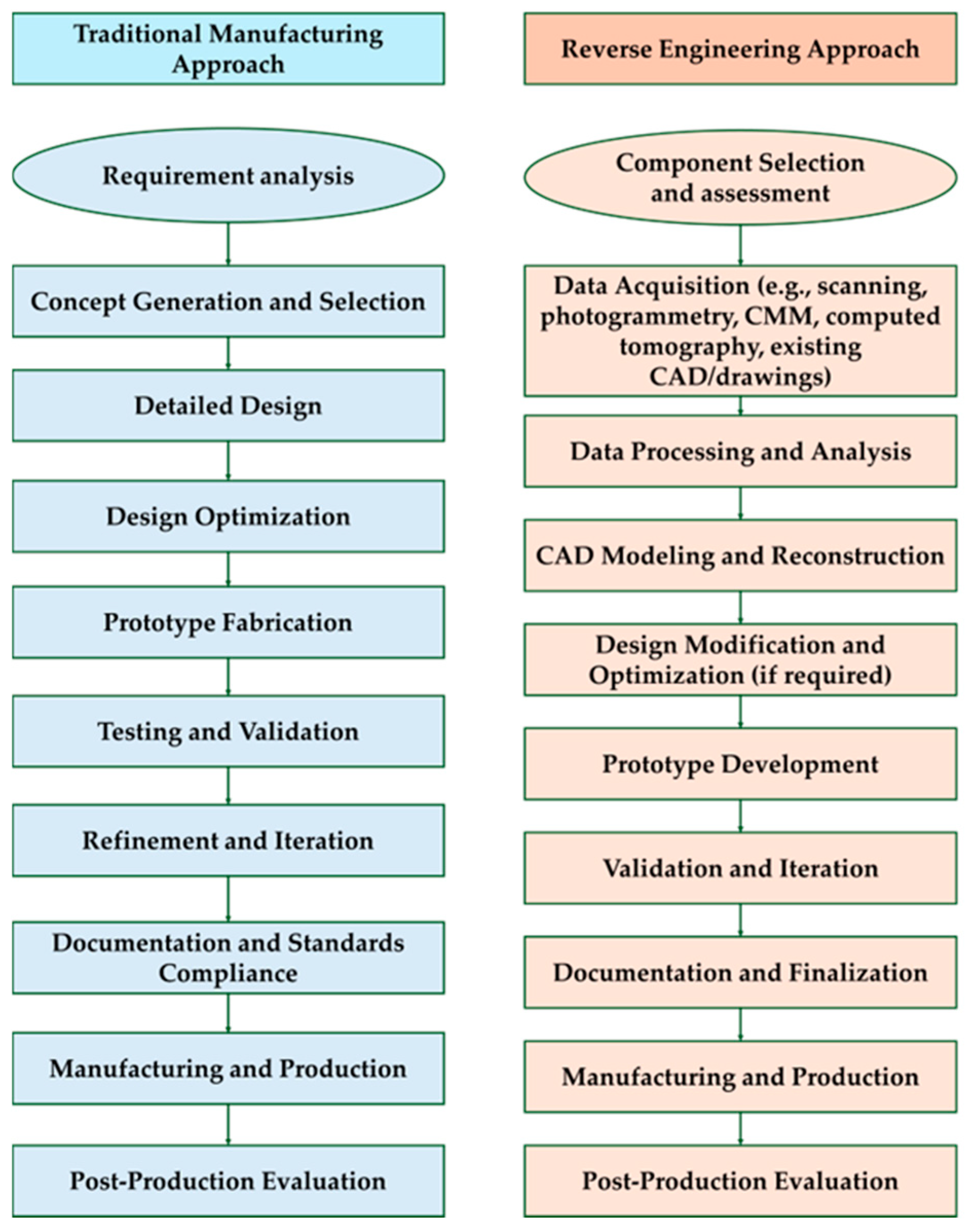
Figure 1. Comparison of traditional manufacturing vs. RE process.
Metrology 05 00066 g001
Figure 2. Methodological framework of the research.
Metrology 05 00066 g002
Figure 3. Keywords with Boolean operators for identifying relevant studies.
Metrology 05 00066 g003
Figure 4. PRISMA flow diagram of the study.
Metrology 05 00066 g004
Figure 5. Co-occurrence of keywords.
Metrology 05 00066 g005
Figure 6. Workflow of NURBS surface reconstruction from point cloud data using Imageware 13.1. (Adapted from Dong et al. [29]).
Metrology 05 00066 g006
Figure 7. High-resolution 3D reconstruction of a 260 mm propeller blade using Agisoft Metashape and AI-assisted tools (adapted from Faizin et al. [55].
Metrology 05 00066 g007
Figure 8. Results of point cloud reconstruction, (a) the input point cloud data and (b) the generated CAD model. (Adapted from Zhang et al. [56]).
Metrology 05 00066 g008
Figure 9. Technology tree linking scanning methods, data processing tools, CAD platforms.
Metrology 05 00066 g009
Figure 10. Inadequate capture of threads and hole geometry in 3D scan. (a) 3D-scanned point cloud in component with thread. (b) Issue in capturing hole and noise.
Metrology 05 00066 g010
Figure 11. Specular reflection artifacts in 3D scan of a U-shaped component.
Metrology 05 00066 g011
Figure 12. Visual Representation of Error Overlay in Product Remanufacturing Process (Self illustration with the ideation from Geng & Bidanda [6]).
Metrology 05 00066 g012
Table 1. Research protocol of research.
Review typeSystematic review
DatabasesGoogle Scholar, Web of Science, Scopus, University of Oklahoma library
Paper Search StrategyBoolean logic using keyword clusters
Paper selection tacticsBased on Preferred Reporting Items for Systematic reviews and Meta-Analyses (PRISMA) framework
LanguageEnglish only
Timeline (Year)2005–2025
Inclusion criteria
  • Strong empirical data, case studies, simulations, or experimental results
  • Peer-reviewed research
Exclusion criteria
  • Insufficiently detailed studies on RE in mechanical components
  • Limited relevance to addressing RQs
Table 2. Comparative evaluation of RE features across various publications.
Author & Year3D Scanning UsedInternal Geometry ReconstructedSimulation/FEA UsedAdditive ManufacturingSubtractiveFunctional OptimizationDocumentation/Redesign Purpose
Urbanic [23]
Osipov et al. [24]
Zhu et al. [25]
Zhao et al. [26]
Freddi et al. [5]
Sedlák et al. [27]
Sukumar et al. [28]
Dong et al. [29]
Huang et al. [30]
Wang et al. [31]
Patpatiya et al. [32]
Li et al. [33]
Sun et al. [34]
Chiriță et al. [35]
Rao et al. [36]
Wang et al. [37]
Hwang & Kim [38]
Gameros et al. [39]
Kašpar et al. [40]
Lee et al. [41]
✓: Part of the study; ✗: Not part of the study.
Table 3. Application of various scanning to CAD modeling methods for RE mechanical components.
Author & YearScanning TechniqueScan Data Processing SoftwarePost Processing CAD SoftwareApplication
Subeshan et al. [71]Non-contact laser scanning (HandySCAN 700 Scanner)VX Element 7.0Fusion 360Stainless-steel lever
Pang & Fard [72]Non-contact scanning (Flexscan and PSV-400 Scanner, Polytec Inc., Irvine, CA, USA, coupled with the Polytec scanning program)Defeature tool of GeomagicCATIABell crank of a sidecar racing
Helle & Lemu [73]Handheld non-contact 3D laser scannerVX Scan and ModelAutodesk InventorMetal cylinder
Buonamici et al. [74]3D optical scanning (Romer RS1 on 7520-SI Absolute Arm by Hexagon metrology, Stockholm, Sweden)RapidWorks (NextEngine version of Geomagic Design X)Siemens NXElectrical socket adapter (real part)
Yahaya et al. [75]Non-contact 3D scanning with image capture (Sense 2 3D Scanner)Not specifiedSolidWorksHonda billet distributor cover (automotive part)
Urbanic [23]Non-contact laser scanning (Metris® LC50 mounted on DEA CMM)Metris® scan curvature filter, Paraform®Not explicitly stated (Paraform used for surfacing)Valve cover, stamped panel, differential carrier
Zhang et al. [76]Structured-light optical 3D scanning (OptimScan-5M, Shining 3D, Hangzhou, China)-Not explicitly statedPre-repair modeling of worn H13 tool steel block and casting die
Faizin et al. [55]Photogrammetry (Sony A6000 camera, Tokyo, Japan) with calibrated targetsAgisoft Metashape, Google Colab + Blender + MeshroomSolidWorks 2019 (Mesh2Surface add-in)Boat propeller blade (marine application)
Roos et al. [65]Neutron tomography (neutron CAT scanning mode)Octopus (reconstruction), VGStudioMaxNot specifiedInternal geometry of IS-60 Rover gas turbine components (e.g., diffuser, shaft, combustor liner)
Deja et al. [77]Laser scanning (MMDx 100 on SMART Arm 7-axis system)Geomagic Design X, Geomagic WrapAutodesk InventorPropeller shaft housing (marine propulsion system)
Afeez et al. [78]Coordinate measuring machine (CMM) and manual methodsIDEAS NX 12IDEAS NX 12Crane cabin (TFC 280) with 300+ sheet metal parts
Gameros et al. [39]Optical scanning (3Shape Q800) + X-ray CT (Zeiss METROTOM 1500)Convince Analyzer + STL/NURBS reconstructionNot specifiedNickel-based turbine blade with internal cooling channels
Othman et al. [44]Laser scanning (Freescan UE-11, blue laser)-Autodesk Inventor, Altair InspireBrake calliper (Volkswagen Golf Mk6) redesign via RE and AM
Wang et al. [37]Not specified (framework assumes mesh input)Custom Visual C++ with OpenGLBased on Open CASCADECAD model reconstruction from mesh data (e.g., blade, aircraft part, mechanical housing)
Wang et al. [31]Non-contact laser scanning (TianYuan OKIO-B-400)Point cloud filtering, NURBS surface fitting in ImagewareUG (Siemens NX), ANSYS WorkbenchFreeform surface acquisition and simulation-driven redesign of pump impeller
Rao et al. [36]Photogrammetry (image-based 3D reconstruction)Incremental Structure-from-Motion + Multi-view stereo + Delaunay triangulationSolidWorks (visualization only)Detection of internal defects in aluminum specimens using ERTM with point cloud-based geometry
Chiriță et al. [35]Structured-light scanning (EinScan-SP V2)-SolidWorksRemanufacturing hydraulic flowmeter rotor using RE and additive manufacturing
Li et al. [33]Structured light scanning (GOM ATOS II-400)Point cloud preprocessing, PCS + modified ICPPro/Engineer, CATIAReconstruction and repair of worn forging die and gear bracket using RE-aided additive/subtractive remanufacturing
Osipov et al. [24]Laser scanning (Shining 3D FreeScan UE Pro, Hangzhou, China)FreeScan software, Geomagic Design XGeomagic Design XRE of Capstone C 65 micro-GTU combustion chamber for 3D modeling and documentation
Zhu et al. [25]Non-contact 3D scanning (OKIO-B, Beijing TenYoun 3D Technology Co., Ltd, China)Geomagic Studio 11SolidWorks 2015Remanufacturing of broken 45 steel gear tooth using RE and laser cladding
Dong et al. [29]Milling-based slicing with CCD imaging systemMATLAB, Imageware 13.1UG, Imageware3D reconstruction from cross-sectional images for components with internal geometry
Freddi et al. [5]Laser scanning (FARO Quantum S with probe, Headquartered in Lake Mary, Florida, United States)Geomagic Design XGeomagic Design XRE and performance optimization of KTM racing connecting rod
Zhao et al. [26]Laser scanning (3D Family laser scanner)Geomagic Studio (point cloud cleanup, IGES export)UG NX (for tool path planning)RE, laser additive repair, and milling of KMN steel compressor blades
Huang et al. [30]3D scanning with Power Scan-Pro scannerIntegral iteration methodSolidWorksIncomplete information reconstruction and remanufacturing of turbine blades using RE, FEA, and laser cladding
Table 4. Identified Problems and Solutions in RE of Mechanical Parts.
CategoryChallenge/Issue IdentifiedSolution/RecommendationAuthor and Year
Product Complexity, Internal Geometry, and Physical BarriersLack of knowledge about which information is pertinent vs. superfluousDefine a taxonomy and analyze in a controlled reference frame where all info is assumed pertinentHarston and Mattson [80]
Internal/hidden features and hollow geometries are difficult to capture, especially in complex partsUse multimodal scanning (CT + structured light/laser); recreate hollows via CAD operations (e.g., extruded cuts)Geng & Bidanda [6]; Yahaya et al. [76]
Assemblies with mixed materials (e.g., steel vs. aluminum) create invisibility in scansSeparate components by density or pixel count; export as separate STL filesRoos et al. [65]
Absence of 3D CAD data and technical specs for legacy partsUse RE combined with additive manufacturing (AM) to reconstruct parts from scan data and system analysisLópez & Vila [10]
CT scans struggle with dense materials due to scatter/beam hardeningSupplement CT with optical scansGameros et al. [39]
Freeform and curved geometries (e.g., propeller blades) are hard to measureApplication of photogrammetry-based RE (Agisoft Metashape + CAD)Faizin et al. [55]
Existing hole-repair/interpolation methods fail in high-curvature regionsDeveloped an outlier-plane based hole repair methodSun et al. [34]
Tolerance, Dimensional Accuracy, and Error PropagationDimensional errors accumulate across RE–AM workflowApply tolerance stacking and process controlGeng & Bidanda [6]; Forslund et al. [86]
CAD models of worn parts misrepresent original tolerancesAvoid worn regions; apply correction ratios; Use unit step integral iteration method to register damaged point cloudJamshidi et al. [83]; Huang et al. [30]
Automated tolerance estimation is limited; manual assignment is error-prone and time-consumingDevelop surface texture–based conversion tables; apply hybrid/manual methods (MATLAB, Excel)Jamshidi et al. [83]; Kaisarlis et al. [82]
Non-uniform rational B-spline (NURBS) method captures roughness well but fails to extend internal geometryPropose a hybrid method using primitives for internal structure and NURBS for external geometryHelle & Lemu [73]
Difficulty in aligning partial scans, defining datums, and managing symmetriesUse Iterative Closest Point (ICP)/global registration; apply knowledge-based rules for datum selection; validate through iterative optimizationBuonamici et al. [74]; Kaisarlis et al. [82]; Freddi et al. [5]
Difficulty in assessing measurement uncertainty for internal structures and freeform surfacesProposed a modular freeform gage (MFG) using ISO 15530-3 [95] to enable uncertainty estimation and traceability for RE of complex surfacesGameros et al. [39]
Scanning Limitations and Data Acquisition ChallengesVarying and unknown product complexityDecompose product into information types (e.g., geometry, material)Harston & Mattson [80]
Scanning accuracy affected by material reflectivity, transparency, surface flaws, and environmental conditionsUse powder/matte coatings; maintain stable conditionsPang & Fard [72]; Tóth & Živčák [88]
STL-based issues: lack of datum planes, poor scaling, no curvature, missing parametric/semantic dataAdjust scaling/planes before CAD import; rebuild geometry via triangulation; apply feature recognition to restore parametric modelsRoos et al. [65]; Forslund et al. [86]
Reflective surfaces and misaligned markers cause scan failureUse reference geometries (e.g., plastic pyramid) and rotate partsHelle & Lemu [73]
Mesh quality issues: noise, holes, discontinuities, outliers, and free-standing trianglesUse mesh cleaning, smoothing, and repair (e.g., Geomagic fill/bridge/Relaxpolygons; noise filters)Deja et al. [77]; Geng & Bidanda [6]; López & Vila [10]; Šagi et al. [63]; Pang & Fard [72]; Yahaya et al. [76]
Photogrammetry heavily depends on photo quality, lighting, and anglesCapture dense, well-distributed images (e.g., 40+) and process with advanced softwareFaizin et al. [55]
Process Integration, Post-processing ChallengesCritical manufacturing details (e.g., heat treatment) often missed, leading to part failureCapture post-processing info alongside geometry/materialCurtis et al. [19]
RE data (point clouds, meshes, models) poorly integrated into PLMStandardize formats and annotate metadata for traceabilityForslund et al. [86]
Difficulty selecting AM/CM processes and materials for spare part recoveryUse structured RE-AM methodology with criteria (lead time, cost, performance)López & Vila [10]
Topology optimization produces non-manufacturable outputsRe-model in CAD with fillets and smoothed profilesPang & Fard [72]
Human, Material, and Process-Specific LimitationsLack of operator skills leads to misinterpretation of design intentUse experienced multidisciplinary teams and specialized RE softwareCurtis et al. [19]; Freddi et al. [5]
Lack of tolerance data makes CAD model creation experience-drivenDevelop tolerance approximation methods using surface/machining texturesJamshidi et al. [83]
Used parts exhibit uncertain geometry/damage (wear, corrosion, stress)Apply finite element analysis to predict life and remanufacturing worthinessHuang et al. [30]
Lack of traceability and accuracy in optical scanning validationUse tactile CMM and modular freeform gages as referenceGameros et al. [39]
Disclaimer/Publisher’s Note: The statements, opinions and data contained in all publications are solely those of the individual author(s) and contributor(s) and not of MDPI and/or the editor(s). MDPI and/or the editor(s) disclaim responsibility for any injury to people or property resulting from any ideas, methods, instructions or products referred to in the content.