Abstract
A calibration system was designed to evaluate the accuracy of linear optical encoders at the micron level in a fast and economical manner. The system uses a commercial interferometer and motor stage as the calibrator and moving platform. Error analysis is necessary to prove the effectiveness and identify areas for optimization. A fixture was designed for the scale and interferometer target to meet the Abbe principle. A five-degree-of-freedom manual stage was utilized to adjust the reading head in optimal or suboptimal working conditions, such as working distance, offset, and angular misalignment. The results indicate that the calibration system has an accuracy of ±2.2 μm. The geometric errors of the calibration system, including mounting errors and non-ideal motions, are analyzed in detail. The system could be an inexpensive solution for encoder manufacturers and customers to calibrate a linear optical encoder or test its performance.
1. Introduction
Optical encoders are currently the most commonly used sensors for precision displacement measurement and positioning [1,2,3]. With the rise of intelligent manufacturing, there has been an explosive growth in the production and use of optical encoders. As a result, there is an increasing demand for calibration services from both manufacturers and customers. Researchers have already focused on the issue of encoder calibration, but a large part of previous work is about rotary encoders [4,5,6,7,8,9,10].
Researchers have developed several methods for calibrating linear optical encoders. Kajima and Minoshima proposed an upgraded nanometer-length calibrator that uses an optical-zooming laser interferometer with an optical frequency comb. The calibration uncertainty of this method is 0.55 nm [11,12]. Yu et al. designed a high-precision comparator with a macro–micro dual drive for calibrating non-contact incremental linear encoders. The measurement and motion resolution of the comparator are 1 nm and 3 nm, respectively [13]. Gurauskis et al. developed a thermal and geometric error compensation system for a linear optical encoder [14]. The system consists of a moving carriage with aerostatic bearings on a granite base. Keysight laser and interferometer components are used as length standards. Hu et al. investigated an incremental optical linear encoder error model, specifically examining the influence of different temperatures [15]. The experiments used a commercial interferometer, Renishaw XL-80, as a calibrator. Taniguchi et al. proposed an advanced calibration system that uses a grating-interferometer-type hologram scale. This system fulfils the accuracy and stability requirements for a linear encoder with sub-nanometer resolution [16]. The most accurate traceable calibration method for linear optical encoders involves using a length scale interferometer in metrological institutions [17], e.g., the Nanometer Comparator at PTB, Germany [18,19]. However, whether the measurement uncertainty of the length scale interferometer is in sub-, several-, or tens-of-nanometers, it is still a specially designed, highly customized, and prohibitive instrument for most manufacturers.
In the field of linear optical encoder calibration, we aimed to address an important question: can an economical and convenient calibration system be developed to meet the demands of the rapidly growing encoder industry? To achieve this, we designed a calibration system for linear optical encoders using a commercial interferometer and motor stage. The system has been used to test and calibrate a customized linear optical encoder in development, whose scale length is 20 mm, and the target accuracy is ±2.5 μm. In the experiments, an SIOS interferometer is used as a calibrator. The motor stage is economical and convenient, but not as precise as air-bearing stages. Therefore, error analysis is necessary to prove its effectiveness and identify areas for optimization. The results show that the calibration system has an accuracy of ±2.2 μm. The perturbation of the commercial motor stage limits the system for static calibration. The geometric errors of the calibration system, including mounting errors and non-ideal motions, are analyzed in detail. The system could be an inexpensive method for encoder manufacturers and customers to calibrate a linear optical encoder or test its performance.
2. Design of the Calibration System
2.1. Abbe Configuration of the Calibration System
We mentioned several ways to calibrate linear optical encoders in Section 1, but the essence of all of them is to generate a motion and measure that motion simultaneously with the calibrator and the sensor being calibrated. There are two main requirements for the calibrator: (1) the measurement uncertainty of the calibrator should be better than the linear optical encoders, usually an order of magnitude higher; (2) the measurement range of the calibrator should be large enough to cover the sensor being calibrated. Therefore, interferometers (including grating-based ones) are the most commonly used calibrators, just as in the aforementioned works.
The most critical principle in designing the calibration system is the Abbe principle [20]—namely, the measurement arm of the interferometer should be in line with the pitches of the encoder (see Figure 1). More strictly, the driving direction and measuring axes should also be co-linear. Since most of the commercial motor stages could not meet this requirement, as a result, the influence of tilts on the measurement will be amplified. Further discussion is in Section 3.
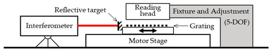
Figure 1.
Schematic of the calibration system for the linear optical encoder in Abbe configuration.
2.2. Design of an Economical On-Site Calibration System
Aiming for an economical and on-site system, a calibration system was designed to maximize the use of commercial components. The 3D model and the real system are shown in Figure 2. As Figure 2 shows, a commercial interferometer (model: SP5000 NG, SIOS Meßtechnik GmbH, Illmenau, Germany) is used as the calibrator, the accuracy of which is ±0.1 μm/m and the resolution of which is 0.1 nm. A 50 mm linear motor stage (model: MTS301, Beijing Optical Century Instrument Co., LTD., Beijing, China) is used as the moving platform carrying the grating scale and the mirror. Since the scale length of the linear optical encoder is 20 mm, there is no need to equip a particularly long motor stage. The grating scale is placed right in the middle of the platform, which is the nearest to the driving screw. The special fixture is designed to meet the Abbe principle; in the current configuration, a sample grating scale is adhered to the fixture for the best stability. The centre of the mirror (or a retro-reflector) is placed on the extended surface where the grating pitches are located. Above the grating, the sensing head of the optical encoder is mounted on a mechanical assembly for fixture and 5-DOF (degree-of-freedom) adjustment. An adjustable mount (model: DGA-25, Newport Corporation, Irvine, CA, USA) with a customed fixture is used for rotating the sensing head (model: M05, Celera Motion Company), while a two-DOF translational manual moving stage is used to set the working distance and offset of the sensor. The resolution of the linear optical encoder is better than 20 nm. The adjustment of the system is described in Section 3.1, after geometrical analysis.
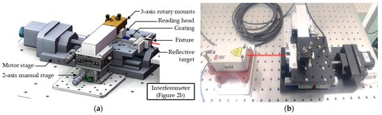
Figure 2.
Model (a) and picture (b) of the economical and on-site calibration system of linear optical encoders.
It should be specified that a commercial sensing head (instead of the aforementioned customized one) is used in the experiments for a stable performance without faults and failures.
In the prototype, a 50 mm motor stage is used for a 20 mm grating scale. The total size of the calibration system is about 550 mm × 250 mm× 100 mm, which is convenient for shipment. In addition, the calibration system is highly modularized and easy to upgrade.
2.3. Uncertainty Budget of the Calibration System
An important issue of the on-site economical calibration of linear optical encoders is the uncertainty budget. Different from the integrated instruments, the uncertainty budget of the calibration system combined with several components is dependent on both the off-the-shelves components and the original components of the laboratory.
The considered sources from the off-the-shelves are as follows: (1) the measurement uncertainty of the reference laser interferometer; (2) errors caused by angular misalignment; (3) errors caused by temperature and its changes. The considered source from the original components of the laboratory is mainly (4) the temperature changes affecting the platform where the system is set up.
Then, the estimation of the calibration system is made as follows. According to the technical sheet of the interferometer, the measurement uncertainty is 0.15 ppm. Considering the 20 mm scale length and maximizing the environmental influence on the 200 mm dead path, the first source of uncertainty is estimated as 0.033 μm.
The angular misalignment is caused by two aspects, assembling errors and the guide rail. The assembling errors between the laser interferometer and the encoder scale after adjusting could be estimated as ±1 mrad. Provided by the manufacturer, the unstraightness of the guild rail is about ±5 μm, while the corresponding angular misalignment is estimated as ±100 μrad. The total angular misalignment involves two parts: ±1 mrad for static calibration and ±100 μrad for dynamic calibration. According to the analysis in Section 3, the second source of uncertainty is estimated as 0.183 μm.
Considering that the on-site system may not have an environment that is carefully controlled, we suppose that the fluctuation of the environment temperature is ±3 degrees and the temperature changes during one test (about several seconds) is 0.2 degrees. The material of the 20 mm encoder scale is soda-lime glass, whose coefficient of thermal expansion (CTE) is about 8 × 10⁻⁶ K−1. The material of the optical table surface is X6Cr17, whose CTE is about 10.5 × 10⁻⁶ K−1. Since the encoder scale works as the benchmark, the absolute temperature matters. The zero-point of the interferometer is on the same side as the encoder, and the change in dead path caused by the absolute temperature is 63 μm, which could be ignored. But the temperature changes during one test could be considered and the resulting uncertainty is 1.05 μm (supposing the influenced length is 0.5 m). In addition, the environmental influence of the commercial interferometer is compensated for, so we categorized it as the first uncertainty source. But it is indeed an important part of uncertainty and it is in our plan to carry out further work with a custom-designed interferometer.
Since converted the uncertainty sources above into displacements, the uncertainty budget is listed in Table 1.

Table 1.
Uncertainty budget of the on-site economical calibration system.
According to the data in Table 1, the expanded uncertainty (k = 2) is 2.133 μm for the 10 mm displacement test.
2.4. Experiment Results of the Calibration System
The experiment results (after linear error compensation) are shown in Figure 3, Figure 4 and Figure 5. Firstly, the platform moved 10 mm at a maximum speed of 2.5 mm/s. The sample rates of both the interferometer and the linear optical encoder are 10 Hz. As Figure 3a shows, the curves fit well with each other, even in the acceleration and deceleration periods. Data at the endpoints are 9983.10 μm (optical encoder) and 9983.0674 μm (interferometer), respectively. Since the sample time of the optical encoder and the interferometer are unsynchronized, the derivation data shown in Figure 3b are linearly interpolated. Deviation of the 10 mm motion is within ±30 μm, which is mainly contributed by the straightness and the interpolation process. A perturbation with a period of 4 mm can be observed from the deviation data, which is consistent with the thread guidance of the motor stage.
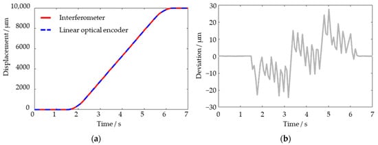
Figure 3.
Experiment results (a) and deviation (b) for 10 mm motion of the platform.
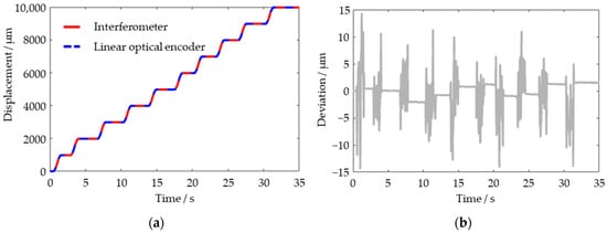
Figure 4.
Experiment results (a) and deviation (b) for 1 mm stepping motion of the platform.
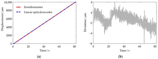
Figure 5.
Experiment results (a) and deviation (b) for 10 mm motion of the platform with low-velocity.
Further, the platform was driven in continuous 1 mm steps. As Figure 4 shows, the 1 mm steps are too short to fully accelerate, so the maximum velocity is about 1.4 mm/s. As a result, the perturbations during the motion of the motor stage are significantly reduced. Figure 4b shows that the deviations during the moving period are within ±15 μm, while the deviations during the stable period are within ±2.2 μm.
To further prove the velocity-related feature of the perturbation, another 10 mm displacement is driven at 0.125 mm/s. As Figure 5 shows, the deviation during the low-velocity moving period is within ±8 μm. The experiments above demonstrate the performance of the proposed calibration system in the current configuration. The results of the perturbation reveal that the system might only be effective in static calibration.
The velocity-related perturbation could also explain the difference between the experiment results and the uncertainty budget. There are two main reasons for this: the angular misalignment tolerance and the nonlinearity of the encoder. In the experiments, the target of the SIOS interferometer is a plane mirror, limiting the angular misalignment tolerance to ±430 μrad. Because the dynamic angular misalignment might be larger than ±100 μrad, the signal-to-noise ratio (SNR) of the interferometer becomes worse when the stage is moving. The influence of the descending SNR, the cosine error, and the Abbe error together form a part of the observed perturbation. The other part is the nonlinearity of the encoder caused by the non-equal amplitude, non-equal-bias and non-orthogonal signals.
3. Error Analysis
Error analysis for an interferometer-based calibration system is not a novel issue [21,22,23,24]. It is important for calibration systems, especially for economical systems, because commercial interferometers and motor stages vary widely in type, cost, and performance. There are two main necessities for the error analysis of an economical calibration system for a linear optical encoder: (1) optimization of the error budget and economic budget; (2) optimization of the performance of the calibration system by compensation methods.
The main error sources of the calibration system could be categorized into two parts, the environment error and the geometric error. Since the environmental error of an interferometer is deeply investigated and the air refractive index of a commercial interferometer could be compensated, we mainly analyze the geometric error in this section. Both mounting misalignments (static) and non-ideal motions of the motor stage (mostly dynamic) contribute to the geometric error.
3.1. Mounting Misalignments
Mounting misalignments determine the static performance of the calibration system. Schematics of mounting misalignments are shown in Figure 6. One must imagine that the movable stage is in an ideal position, while the other components, including the interferometer, the reflective target, the grating, and the reading head, are all with mounting misalignments.
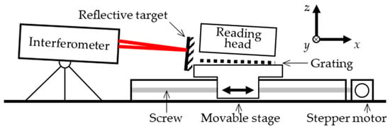
Figure 6.
Schematic of the geometric error sources of the calibration system.
As a result of the misalignments, cosine error has always existed in the process of mounting and adjusting the interferometer and the reflective target. The features of mirror and retro-reflector targets are different. As Figure 7a shows, the laser beam emits perpendicularly to the interferometer at a random angle β, and then incident beam is directed at a mirror target at an oblique angle to the beam. If the beam derivation does not exceed the detecting range, the change in the optical path could be expressed as
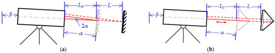
Figure 7.
A 2D schematic of the cosine error of mirror (a) and retro-reflector (b).
According to the technical sheet of the interferometer [25], the maximum tilting angle with a plane mirror is ±1.5 arcmin (≈±4.36 mrad). The limited tilting angle is the angle α in Equation (1), which means the Δxmirror is approximately 2L/cosβ.
As Figure 7b shows, if the mirror is replaced by a retro-reflector that is insensitive to the incline incident beam, the angular mismatch of the interferometer will become an offset mismatch. The change in the optical path length could be expressed as
Although the tilting angle with a retro-reflector could be as large as ±22.5°, since the angle β is quite a small angle, the ΔxRR could also be 2L/cosβ. No matter whether the approximation is considered or not, the changes in the optical path length for both mirror and retro-reflector are in proportion with the displacement of the movable platform L. As a result, the mounting error affects the interferometer by inducing a coefficient. It should be stressed that the analysis in this section is a 2D case, but the actual system is a 3D case. Then, the derivation process of the model is more complicated—ray tracing with vectorial optical formulae is effective in solving the 3D problem. A prediction of the results is that if the angles α and β are regarded as spatial angles of the beam vectors, the approximate results will still be 2L/cosβ.
Further, the position of the grating is additionally taken into consideration. In an ideal calibration, the direction of grating pitches should be in parallel with the laser wavelength (no matter if they are in parallel with the movable platform). But in an actual system, only the projection of grating pitches is taken into account. As Figure 8 shows, if the pitch and roll angles of the grating are not zero, the projection of grating pitches in the wavelength direction will change. The changes lead to cosine errors, as shown below.
where OPL is the changed optical path length, φ is the phase measured by the linear optical encoder, and g is the ideal grating pitch. Equations (1)–(4) demonstrate that the mounting misalignments cause a linear error in the calibration system, which could be compensated for in the testing of the system.
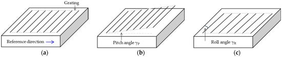
Figure 8.
Cosine error of the grating. (a) Ideal case. (b) Pitch angle. (c) Roll angle.
The misalignments of the reading head influence the sine and cosine signals of the optical encoder, causing nonlinearity errors. These errors can be compensated for by algorithms in the phasemeter. During the calibration process, the reading head should be adjusted to an ideal position for optimal signal-to-noise ratio and performance. In some cases, the calibration system may be used to test the performance of the alignment tolerance by adjusting the reading head to a worst-case scenario.
The results above are helpful in the alignment process of the calibration system. Due to the use of commercial off-the-shelf components, on-site calibration systems may require multiple recalibrations, with each recalibration requiring a calibration process significantly increasing the costs. The alignment process involves four parts: the interferometer, the mirror (or the retro-reflector), the motion stage, and the grating scale. According to Equation (2), the approximate results are only related to the angle β of the interferometer; thus, the alignment between the interferometer and the motion stage is mainly determined by the angle β. With the help of an aperture (or similar components), it is easy to adjust the beam of the interferometer to be in parallel with the optical platform. Then, the angle α of the mirror (or the retro-reflector) could be observed from the interference signal of the interferometer. The best case occurs when the contrast of the interference signal is highest within the moving range, which could be achieved by adjusting the mirror (or the retro-reflector). The alignment of the mirror (or the retro-reflector), the motion stage, and the grating scale depend on the high tolerance requirement of the fixture in Figure 2a. The alignment process could be performed without involving other instruments such as an autocollimator.
3.2. Non-Ideal Motions
The other part of the geometric error is caused by non-ideal motions. It could be influenced by multiple factors, such as the guide rail straightness of the motor stage, the manufacturing error of the guiding screw, residual Abbe distance caused by mounting, and non-coaxial between driving force and the measuring benchmarks.
The experiments in Section 2 have proved that several- to tens-of-micron perturbations during the motion are velocity-related. One of the largest contributors is the non-coaxial problem, which might be a shortcoming of the commercial motor stage in the use of a calibration system. Figure 9 illustrates the driving force and the measuring benchmarks of the calibration system in schematics.
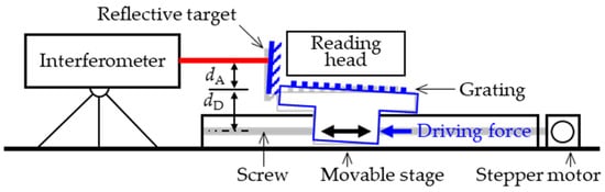
Figure 9.
Schematic of non-coaxial problem. dD, the distance between the driving force and the grating; dA, the residual Abbe distance (exaggerated).
As Figure 9 shows, the driving force from the stepper motor and the screw works on the bottom of the movable stage, while the grating and the reflective target are mounted on the top. Suppose the distance between the driving force and the grating is dD, and the residual Abbe distance is dA. From the real stepper motor stage, the dD is 26 mm. The translational offset between the centre of the mirror (for the interferometer) and the scale (for the optical encoder) is 60 mm. Since the angular misalignment caused by the unstraightness of the guide rail is estimated as ±100 μrad, the maximal result change in the laser interferometer is about ±2.6 μm. But the effect also influences the optical encoder. Supposing that the residual Abbe distance dA is 0.5 mm, the maximal Abbe error (result difference between the interferometer and the optical encoder) is about 0.05 μm.
The results of the non-coaxial problem are also illustrated in Figure 9—the movable stage and the grating and mirror fixing on the stage tilt. The calculation of optical path length and the cosine error is the same as Equations (1)–(4). In Section 2.3, the angular misalignment is estimated as ±(1000 + 100) μrad, and the maximal corresponding cosine error could be calculated as (200 mm + 20mm) × (1/cos(1100 μrad) − 1) ≈ 0.133 μm. Therefore, the uncertainty components of the Abbe error and the cosine error could be estimated as 0.183 μm.
As a result, the tilting angle is not a constant α but a function α(x,t). The variable x represents the position-related factors, such as straightness and manufacturing errors. The variable t represents the time-related factors, for example, the driving force.
4. Discussion
This work mainly focuses on the economical on-site calibration system of linear optical encoder requirements by the encoder producer and user. The calibration system is built by a commercial interferometer and motor stage; therefore, the error analysis is necessary for verifying the calibration ability. Geometric errors including mounting misalignment and non-ideal motion are analyzed in detail. The experiments show that the accuracy of the calibration system is ±2.2 μm. Velocity-related perturbations in several- to tens-of-microns are observed while the stage is moving, the reason for which is regarded as non-coaxial between the driving force and the benchmarks, causing the incline of the stage.
The linear stage is the motion generation device in the system. The experiment results in this work reveal that a stage with a stepper motor is affected by straightness and velocity-related perturbations so it could only be used for static calibration in general accuracy. Longer motor stages could be used to further extend the range of the system. For high-accuracy encoders and dynamic calibration, a stage with a linear motor might have better performance.
There is still plenty of work that must be carried out with this calibration system for linear optical encoders. Recent works are planned as follows:
- An economical interferometer is to be designed to replace the commercial one. The accuracy of the incoming interferometer is determined by error budgeting based on the error analysis.
- The moveable stage is only used for open-loop motion. The system will be further upgraded to a close-loop configuration by using the displacement data from the incoming interferometer. A stage with a linear motor is also in the upgrading plan.
- The performance of the calibration system could be further improved by error compensation algorithms without changing the hardware devices. The artificial neural network method is planned to be used for error recognition.
Author Contributions
Conceptualization, D.C.; methodology, Y.H. and Z.S.; software, Y.H.; validation, Y.S. and D.C.; formal analysis, Y.H. and Z.S.; investigation, Y.H.; resources, J.T.; data curation, Y.H.; writing—original draft preparation, D.C.; writing—review and editing, D.C.; visualization, Y.H.; supervision, J.T.; project administration, J.T.; funding acquisition, D.C. All authors have read and agreed to the published version of the manuscript.
Funding
This research received no external funding.
Data Availability Statement
Data underlying the results presented in this paper are not publicly available at this time, but may be obtained from the authors upon reasonable request.
Acknowledgments
Di Chang cordially thanks Wei Wang, Lin Liu, and Yujia Sun for providing the grating scale and the adjustable mounts; Haijin Fu and Xinkang Xiong for providing the interferometer; Qiushan Chen for her assistance in preparing the original draft.
Conflicts of Interest
The authors declare no conflicts of interest.
References
- Gao, W.; Kim, S.W.; Bosse, H.; Haitjema, H.; Chena, Y.L.; Lu, X.D.; Knapp, W.; Weckenmann, A.; Estler, W.T.; Kunzmann, H. Measurement technologies for precision positioning. CIRP Ann. Manuf. Technol. 2015, 64, 773–796. [Google Scholar] [CrossRef]
- Yu, H.Y.; Chen, X.L.; Liu, C.J.; Cai, G.G.; Wang, W.D. A survey on the grating based optical position encoder. Opt. Laser Technol. 2021, 143, 107352. [Google Scholar] [CrossRef]
- Oiwa, T.; Katsuki, M.; Karita, M.; Gao, W.; Makinouchi, S.; Sato, K.; Oohashi, Y. Questionnaire survey on ultra-precision positioning. Int. J. Autom. Technol. 2011, 5, 766–772. [Google Scholar] [CrossRef]
- Hsieh, T.-H.; Watanabe, T.; Hsu, P.-E. Calibration of Rotary Encoders Using a Shift-Angle Method. Appl. Sci. 2022, 12, 5008. [Google Scholar] [CrossRef]
- Geckeler, R.D.; Fricke, A.; Elster, C. Calibration of angle encoders using transfer functions. Meas. Sci. Technol. 2006, 17, 2811–2818. [Google Scholar] [CrossRef]
- Lu, X.D.; Graetz, R.; Amin-Shahidi, D.; Smeds, K. On-axis self-calibration of angle encoders. CIRP Ann. Manuf. Technol. 2010, 59, 529–534. [Google Scholar] [CrossRef]
- Kinnane, M.N.; Hudson, L.T.; Henins, A.; Mendenhall, M.H. A simple method for high-precision calibration of long-range errors in an angle encoder using an electronic nulling autocollimator. Metrologia 2015, 52, 244–250. [Google Scholar] [CrossRef]
- Deng, F.; Chen, J.; Wang, Y.Y.; Gong, K. Measurement and calibration method for an optical encoder based on adaptive differential evolution-Fourier neural networks. Meas. Sci. Technol. 2013, 24, 055007. [Google Scholar] [CrossRef]
- Ban, J.X.; Chen, G.; Wang, L.; Meng, Y. A calibration method for rotary optical encoder temperature error in a rotational inertial navigation system. Meas. Sci. Technol. 2022, 33, 065203. [Google Scholar] [CrossRef]
- Filatov, Y.V.; Agapov, M.Y.; Bournachev, M.N.; Loukianov, D.P.; Pavlov, P.A. Laser goniometer systems for dynamic calibration of optical encoders. In Proceedings of the Optical Measurement Systems for Industrial Inspection III, Munich, Germany, 23–26 June 2003; pp. 381–391. [Google Scholar]
- Kajima, M.; Minoshima, K. Calibration of linear encoders with sub-nanometer uncertainty using an optical-zooming laser interferometer. Precis. Eng. 2014, 38, 769–774. [Google Scholar] [CrossRef]
- Kajima, M.; Minoshima, K. A precision length calibrator based on the optical zooming positioning stage. Opt. Commun. 2013, 292, 1–4. [Google Scholar] [CrossRef]
- Yu, H.Y.; Liu, H.Z.; Li, X.; Ye, G.Y.; Shi, Y.S.; Yin, L.; Jiang, W.T.; Chen, B.D.; Liu, X.K. Calibration of non-contact incremental linear encoders using a macro-micro dual-drive high-precision comparator. Meas. Sci. Technol. 2015, 26, 095103. [Google Scholar] [CrossRef]
- Gurauskis, D.; Kilikevicius, A.; Kasparaitis, A. Thermal and Geometric Error Compensation Approach for an Optical Linear Encoder. Sensors 2021, 21, 360. [Google Scholar] [CrossRef]
- Hu, F.; Chen, X.D.; Cai, N.; Lin, Y.J.; Zhang, F.J.; Wang, H. Error analysis and compensation of an optical linear encoder. IET Sci. Meas. Technol. 2018, 12, 561–566. [Google Scholar] [CrossRef]
- Taniguchi, K.; Tamiya, H.; Enomoto, T.; Aoyama, H.; Yamazaki, K. Advanced linear encoder calibration system with sub-nanometer resolution. CIRP Ann. Manuf. Technol. 2020, 69, 437–440. [Google Scholar] [CrossRef]
- Coveney, T. A review of state-of-the-art 1D length scale calibration instruments. Meas. Sci. Technol. 2020, 31, 042002. [Google Scholar] [CrossRef]
- Flügge, J.; Weichert, C.; Hu, H.; Köning, R.; Bosse, H.; Wiegmann, A.; Schulz, M.; Elster, C.; Geckeler, R.D. Interferometry at the PTB Nanometer Comparator—Design, Status and Development. In Proceedings of the Fifth International Symposium on Instrumentation Science and Technology, Shenyang, China, 15–18 September 2008; p. 713346. [Google Scholar]
- Köchert, P.; Köning, R.; Weichert, C.; Flügge, J.; Manske, E. Dynamics and control of the PTB Nanometer Comparator. In Proceedings of the ASPE Spring Topical Meeting, Online, 6–8 May 2020. [Google Scholar]
- Zhang, G.X. A Study on the Abbe Principle and Abbe Error. CIRP Ann. Manuf. Technol. 1989, 38, 525–528. [Google Scholar] [CrossRef]
- Dong, X.Y.; Sun, S.H.; Cui, J.Y.; Shen, X.P.; Duan, F.J.; Wang, S.H. Error Analysis of Two-dimensional Grating Calibration System Based on Orthogonal Dual-axis Laser Interferometer. Acta Metrol. Sin. 2019, 40, 36–41. [Google Scholar]
- Qian, Y.; Li, J.; Feng, Q.; He, Q.; Long, F. Error Analysis of Heterodyne Interferometry Based on One Single-Mode Polarization-Maintaining Fiber. Sensors 2023, 23, 4108. [Google Scholar] [CrossRef] [PubMed]
- Haitjema, H. The Calibration of Displacement Sensors. Sensors 2020, 20, 584. [Google Scholar] [CrossRef]
- Ali, A.; Amer, M.; Nada, N. Error analysis of laser interferometric system for measuring radius of curvature. J. Opt. 2023. [Google Scholar] [CrossRef]
- SIOS Meßtechnik GmbH. Laser Interferometer LP-NG Series Technical Data Sheet. Available online: https://www.sios-precision.com/fileadmin/user_upload/Produkte/Produktdetails/Datenblaetter/datasheet-laser-interferometer-SP-NG-engl.pdf (accessed on 26 December 2023).
Disclaimer/Publisher’s Note: The statements, opinions and data contained in all publications are solely those of the individual author(s) and contributor(s) and not of MDPI and/or the editor(s). MDPI and/or the editor(s) disclaim responsibility for any injury to people or property resulting from any ideas, methods, instructions or products referred to in the content. |
© 2024 by the authors. Licensee MDPI, Basel, Switzerland. This article is an open access article distributed under the terms and conditions of the Creative Commons Attribution (CC BY) license (https://creativecommons.org/licenses/by/4.0/).