Article

Cost-Effective and Simple Prototyping PMMA Microfluidic Chip and Open-Source Peristaltic Pump for Small Volume Applications

1
Department of Biomedical Engineering, Ankara University, Gölbaşı, Ankara 06830, Türkiye
2
Stem Cell Institute, Ankara University, Balgat, Ankara 06520, Türkiye
3
Department of Electrical and Electronics Engineering, Ankara University, Gölbaşı, Ankara 06830, Türkiye
*
Authors to whom correspondence should be addressed.
Micro 2025, 5(2), 25; https://doi.org/10.3390/micro5020025
Submission received: 16 February 2025 / Revised: 11 April 2025 / Accepted: 21 April 2025 / Published: 27 May 2025
(This article belongs to the Special Issue Functional Droplet-Based Microfluidic Systems)

Abstract

:
Microfluidic devices are tiny tools used to manipulate small volumes of liquids in various fields. However, these devices frequently require additional equipment to control fluid flow, increasing the cost and complexity of the systems and limiting their potential for widespread use in low-resource biomedical applications. Here, we present a cost-effective and simple fabrication method for PMMA microfluidic chips using laser cutting technology, along with a low-cost and open-source peristaltic pump constructed with common hardware. The pump, programmed with an Arduino microcontroller, offers precise flow control in microfluidic devices for small volume applications. The developed application for controlling the peristaltic pump is user-friendly and open source. The microfluidic chip and pump system was tested using Jurkat cells. The cells were cultured for 24 h in conventional cell culture and a microfluidic chip. The LDH assay indicated higher cell viability in the microfluidic chip (111.99 ± 7.79%) compared to conventional culture (100 ± 15.80%). Apoptosis assay indicated 76.1% live cells, 18.7% early apoptosis in microfluidic culture and 99.2% live cells, with 0.5% early apoptosis in conventional culture. The findings from the LDH and apoptosis analyses demonstrated an increase in both cell proliferation and cellular stress in the microfluidic system. Despite the increased stress, the majority of cells maintained membrane integrity and continued to proliferate. In conclusion, the chip fabrication method and the pump offer advantages, including design flexibility and precise flow rate control. This study promises solutions that can be tailored to specific needs for biomedical applications.

1. Introduction

There are two main types of conventional cell culture: two-dimensional (2D) cell cultures, where cells grow attached to a surface, and suspension cell culture [1]. Despite the numerous advantages of conventional cell culture, such as well-established materials and protocols, standardization, and availability of assays, this method fails to fully capture the nuances of the in vivo cellular microenvironment [2,3]. Consequently, conventional cell culture is insufficient to fully mimic in vivo conditions in experimental studies [4]. Given these limitations, different alternative methods have gained popularity, such as three-dimensional (3D) cell culture [5,6,7] and microfluidic cell culture [8] to address the shortcomings of conventional methods and better mimic in vivo conditions.
As an alternative to conventional methods, microfluidic systems represent an approach to the control and manipulation of fluids through microchannels [9,10]. Microfluidic systems have numerous advantages, including low costs, reduced sample requirements, and minimal energy usage [11]. Recently, these systems have become an attractive option in various fields, including biomedical, medicine, food, and materials science [12]. Microfluidics facilitates the control of cellular microenvironments, thereby enabling a more effective mimicry of in vivo conditions in experimental research [13]. Despite these advantages, the necessity for clean room facilities and sophisticated instrumentation causes significant challenges for the production of microfluidics. Given the high demand for microfluidic technologies, it is essential to develop cost-effective and rapid prototyping methodologies, particularly for point-of-care applications [14]. Chip fabrication has utilized a variety of materials over the past two decades. Microfluidic chips can currently be fabricated using several materials, including glass, silicone, Polydimethylsiloxane (PDMS), Polymethylmethacrylate (PMMA), and paper [15,16]. Silicon or glass were the primary materials used in the fabrication of early microfluidic chips. While these materials possess a high degree of reliability, the fabrication method, known as standard photolithography, is considerably expensive. In the following years, the use of PDMS in microfluidic chip fabrication significantly increased. As an elastomer, PDMS has become one of the most widely used materials in microfluidic applications because of its beneficial properties, including high biocompatibility, gas permeability, elasticity, and transparency. Even though PDMS has significantly contributed to the advancement of microfluidic devices, PDMS-based microfluidic chips usually require large control systems and other detection devices. Additionally, the drawbacks include incompatibility with organic solvents and laborious chip production. Paper-based microfluidic chips are utilized in various applications, including pregnancy testing. The suitability of paper as a microfluidic substrate is attributable to its inherent properties, including user-friendliness, cost-effectiveness, and ease of disposal. Despite offering numerous advantages, paper-based chips suffer from limitations such as limited integration, semi-quantitative detection, flow paths that are too simple, and small size channels that are difficult to realize [17]. Another polymeric material employed in microfluidic device fabrication is cyclic olefin copolymer (COC). COCs have some remarkable advantages, including transparency, amorphousness, and biocompatibility [18]. Moreover, it is relatively affordable and can be processed using various fabrication techniques, including hot embossing, injection molding, and laser ablation [19]. Due to its relevant attractive properties, this thermoplastic material is increasingly used in microfluidic chip fabrication [20]. On the other hand, despite the several benefits of COC, its poor wettability makes it unsuitable for some commonly used hydrophobic liquid reagents. Therefore, the corresponding surface modifications are still necessary to overcome this limitation [21].
In addition to the materials already mentioned, PMMA, a thermoplastic polymer, is among the most favored options. Despite PMMA’s limitation in long-term cellular studies due to its minimal gas permeability [16], it possesses significant attributes, including disposability [22], biocompatibility [23], optical transparency [24], and cost-effectiveness [25]. Compared to silicon-based materials used for microfluidic applications, PMMA is less brittle and does not require expensive manufacturing techniques. Furthermore, PMMA structures can be formed using various techniques such as hot embossing, injection molding, laser ablation, reactive ion etching, or deep UV lithography. These structures exhibit a number of superior mechanical properties compared to PDMS. The mechanical properties allow PMMA to better maintain its original shape under mechanical stress conditions [26].
Precise control of fluid flow is essential in many microfluidic systems. A variety of pump types, such as piezoelectric pumps, syringe pumps, and peristaltic pumps, can provide this control. These pumps range in cost from simple, economical models (<USD 10) to highly precise, sophisticated models (>USD 1000) [27,28,29,30]. Syringe pumps are one of the most widely used for microfluidic chips. Nonetheless, syringe pumps have limitations in certain applications. For example, they are limited to delivering fixed volumes of liquid based on the syringe’s capacity and cannot provide circulating flow within a closed system. Peristaltic pumps are a better option than syringe pumps for some applications. Unlike syringe pumps, peristaltic pumps can maintain recirculating flow within a closed fluidic circuit and are physically separated from the sample by the tubing walls, minimizing contamination and safety risks. Additionally, peristaltic pumps are well suited for dosing and metering fluids, which are common tasks in large-volume liquid handling applications. Recirculating flow is essential for various microfluidic applications, including cell culture, and peristaltic pumps play a key role in this process [29].
In this paper, we present a cost-effective and simple method for PMMA microfluidic chip design, along with the development of a low-cost and precise peristaltic pump that can be easily controlled with a user-friendly application interface. The microfluidic chip fabricated with laser cutting technology offers a low-cost and flexible platform that can adapt to various experimental conditions. Furthermore, the peristaltic pump, constructed with commonly used hardware and open-source software, is a user-friendly and cost-effective option for microfluidic applications. Modeling the interactions of therapeutic systems [31,32,33,34], such as nanoparticles and drug delivery systems, with immune cells and blood cells under dynamic flow conditions is of great importance, and the need for microfluidic systems capable of mimicking such interactions is increasing. For this purpose, we designed and engineered our microfluidic system. Here, we evaluate the performance of the designed microfluidic chip and peristaltic pump system and investigate the potential use of this system in cell culture experiments, especially dedicated to studies with white blood cells. The potential use of this system in studying cellular interactions and its application in biomedical research is demonstrated by cell culture experiments conducted with the Jurkat cell line, which is an immortalized line of human T lymphocyte cells and widely used in immunology and immuno-oncology research [35,36]. The results obtained show that the microfluidic system developed provides a suitable platform for obtaining reliable and repeatable results in cell culture studies. This system can enable further studies for biomedical research and various applications.

2. Materials and Methods

2.1. Materials

The following materials and software were used for microfluidic chip fabrication processes: AutoCAD 2020 (Autodesk, San Rafael, CA, USA), PMMA (Forem Reklam, Ankara, Türkiye), DSA (3M 7955MP, Saint Paul, MN, USA), microscope slide (ISOLAB, Wertheim, Germany), fitting (Nehir Biyoteknoloji, Ankara, Türkiye), epoxy glue (Pattex, Düsseldorf, Germany), silicone microfluidic tubing (Nehir Biyoteknoloji), and Dulbecco’s Phosphate-Buffered Saline (DPBS) (Biological Industries, Kibbutz Beit Haemek, Israel). The following materials and software were used for construction of peristaltic pump system: Arduino UNO R3 (Arduino, Ivrea, Italy), peristaltic pump module (Robotistan, İstanbul, Türkiye), CNC shield v3 (Robotistan), stepper motor driver (DRV 8825), power supply: 12V 2A, DC female barrel to wire jack (Robotistan), Arduino IDE (Arduino), and the C# programming language (Microsoft, Redmond, WA, USA). The following materials were used for in vitro studies: Jurkat cell line, RPMI 1640 Medium-1X (Gibco, Grand Island, NY, USA), foetal bovine serum (Biological Industries), penicillin-streptomycin solution (Biological Industries), CyQuant LDH cytotoxicity assay (Thermo Fisher Scientific, Waltham, MA, USA), and Alexa Fluor 488 Annexin V/Dead Cell Apoptosis Kit (Thermo Fisher Scientific).

2.2. Methods

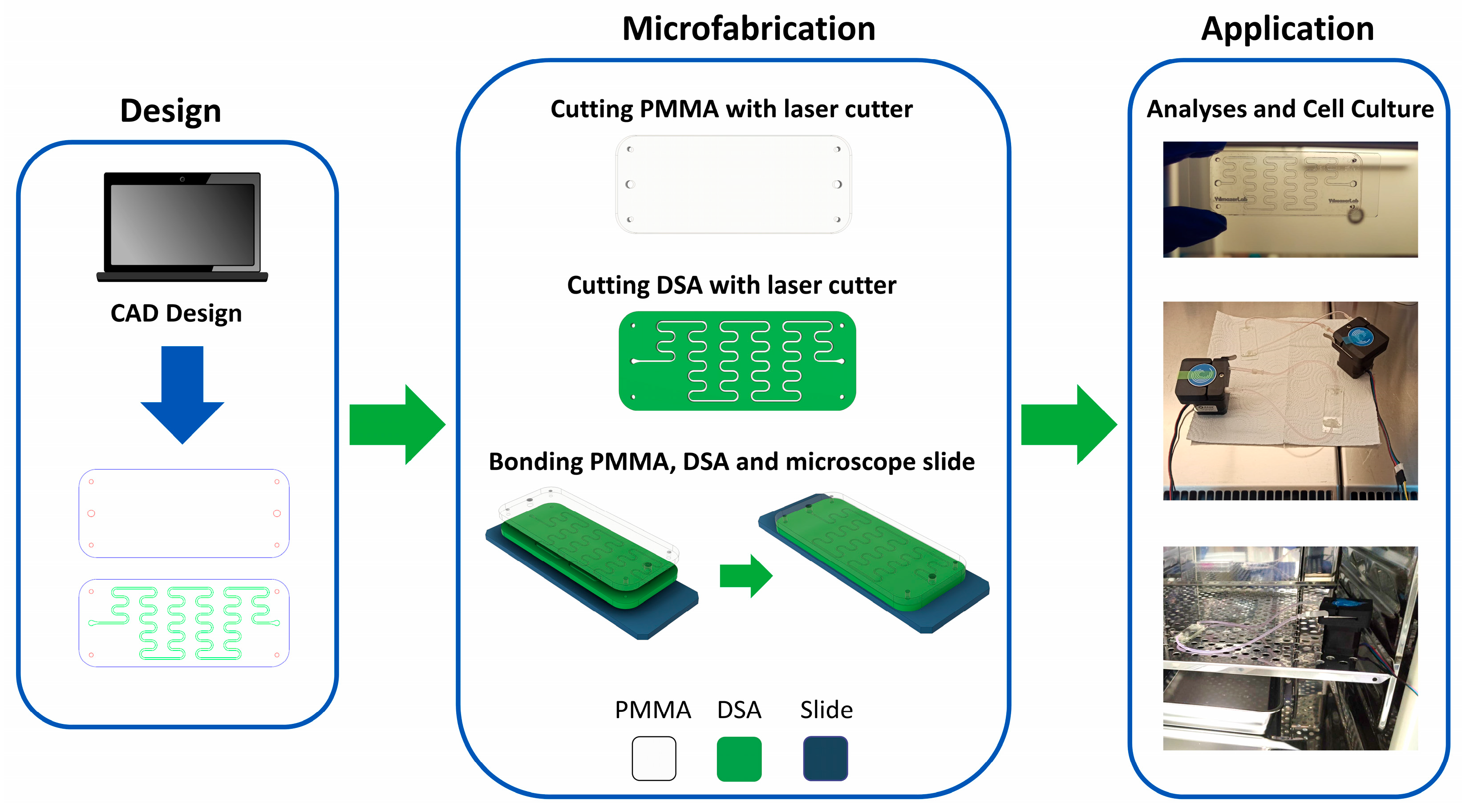
2.2.1. Fabrication of Microfluidic Chips by Laser Cutting Method

The fabrication of the microfluidic chip involved assembling three layers. The bottom layer consisted of a standard microscope slide. The middle layer was a double-sided adhesive (DSA), which is a transfer tape. The top layer was made of PMMA. The method described in previous studies [37,38] was used in the fabrication process. The microfluidic chips were designed in AutoCAD 2020, and the top and middle layers were subsequently produced using a laser cutter (Epilog Laser Mini 24). The manufacturer’s manual [39] was consulted to ensure appropriate cutting parameters were used for layer fabrication.
The bottom layer was a normal 75 mm × 26 mm microscope slide. DSA was used as the middle layer, which formed the channels. Channel geometry plays a significant role in fluid interaction [40]; therefore, serpentine channels were designed to enhance fluid mixing. The top layer was PMMA, which contained the inlet and outlet of the chips. The top layer was designed to be compatible with the middle layer, and transparent PMMA was used to observe the fluid flow effectively. A schematic representation of a microfluidic chip is depicted in Figure 1.
The CAD designs of the microfluidic chip are demonstrated in Supplementary Figures S1 and S2. The chip had one inlet and one outlet. The channel width was 500 μm. The channel length was ~29 cm. The channel volume was ~18.5 μL. The middle layer was patterned on the DSA, and the channel height was 127 μm, corresponding to the thickness of the DSA. Additionally, the diameters of the inlet and outlet on the top layer were 2 mm, and the thickness of the top layer was also 2 mm, corresponding to the thickness of the PMMA.
The designed layers were cut using a laser cutter to produce the top and middle layers. Subsequently, the top, middle, and bottom layers were assembled. During this process, the non-adhesive film on one side of the DSA was first removed, and the PMMA layer was adhered to the exposed surface. Next, the non-adhesive film on the reverse side of the DSA was removed, and the microscope slide was adhered to this surface. To guarantee optimal adherence, minimize bubble formation, and apply uniform pressure, the assembled chip was secured with binder clips and left undisturbed for a certain period. The fabrication process was conducted on a clean and flat surface, which was a laboratory desk (Figure 2). After fabricating the chip, fittings were attached to the inlet and outlet holes using epoxy glue at room temperature, which was then allowed to harden completely. Silicone tubes were subsequently connected to the microfluidic chip through the fittings. The chip was cleaned by sequentially flushing DPBS and medium through the tubes. Finally, the chip was sterilized under UV light for 1 h.

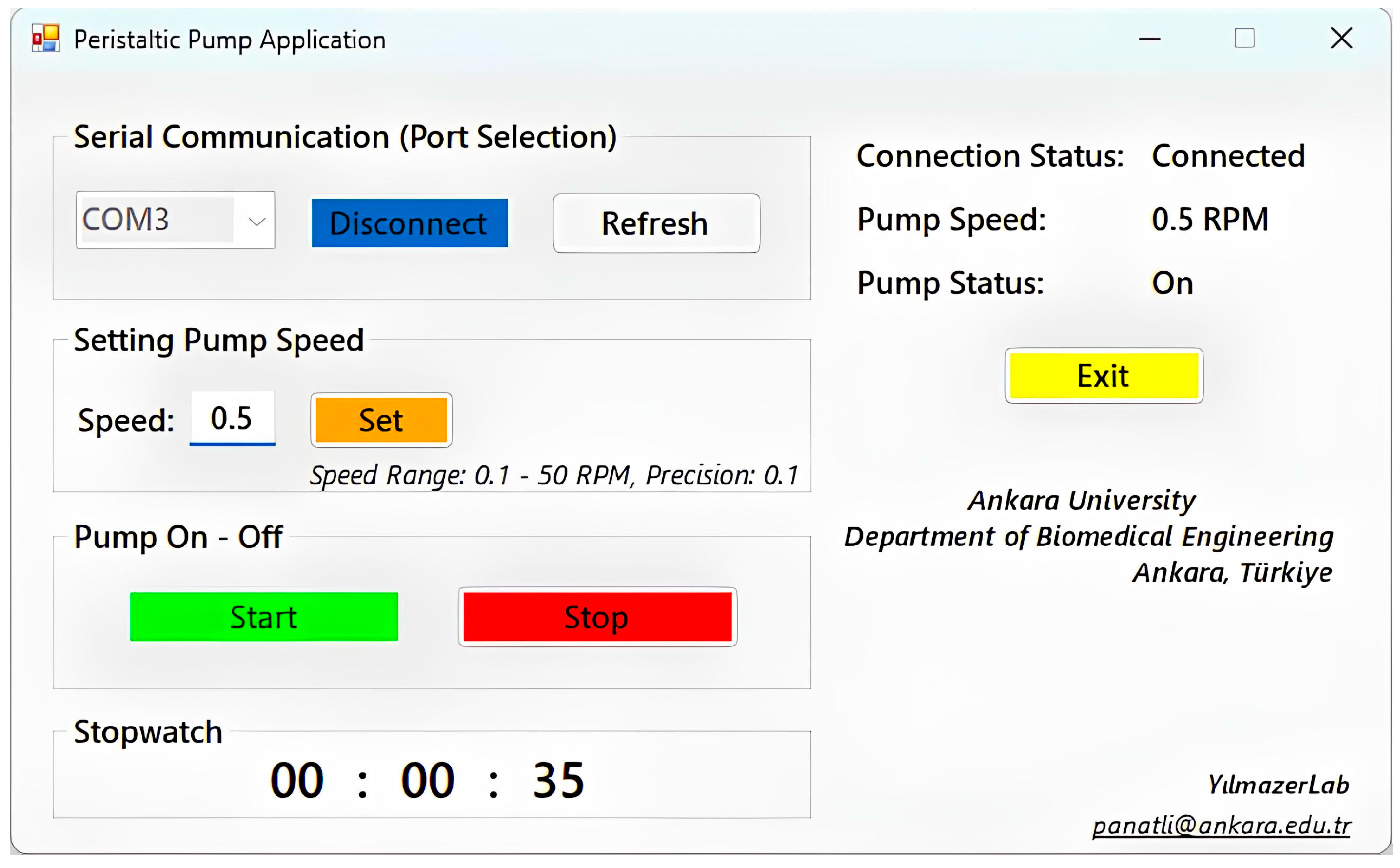
2.2.2. Construction and Control of Peristaltic Pump System

As part of this study, a low-cost peristaltic pump was constructed using commonly available tools and open-source software. The peristaltic pump system consisted of electrical-mechanical hardware and the software. The hardware included a power supply (12 V, 2 A), a microcontroller (Arduino UNO R3), a stepper motor driver (DRV8825), a driver expansion board (CNC shield v3), and a stepper motor-based peristaltic pump module. The schematic and the wiring diagram of the peristaltic pump system are illustrated in Supplementary Figure S3. The Arduino microcontroller was responsible for sending commands to run the peristaltic pump and controlling the speed of the peristaltic pump. Since the peristaltic pump could not be operated by the Arduino alone, the other hardware mentioned above was integrated into the Arduino (Supplementary Figure S4).
The Arduino microcontroller was programmed to control the peristaltic pump using the Arduino IDE, which is an open-source platform, via a USB connection to a computer. Although the peristaltic pump can be controlled through the serial port display of the Arduino IDE, this approach has certain limitations. Specifically, controlling multiple pumps or adjusting their speeds can be time-consuming during experiments. To prevent these challenges, a user-friendly, open-source peristaltic pump application was developed using the C# programming language in the Visual Studio 2019 IDE. This application features a simple and easy-to-use interface, enabling more efficient and convenient control of multiple peristaltic pumps together (Figure 3). The source code and application of the peristaltic pump system are provided in the Supplementary Information.

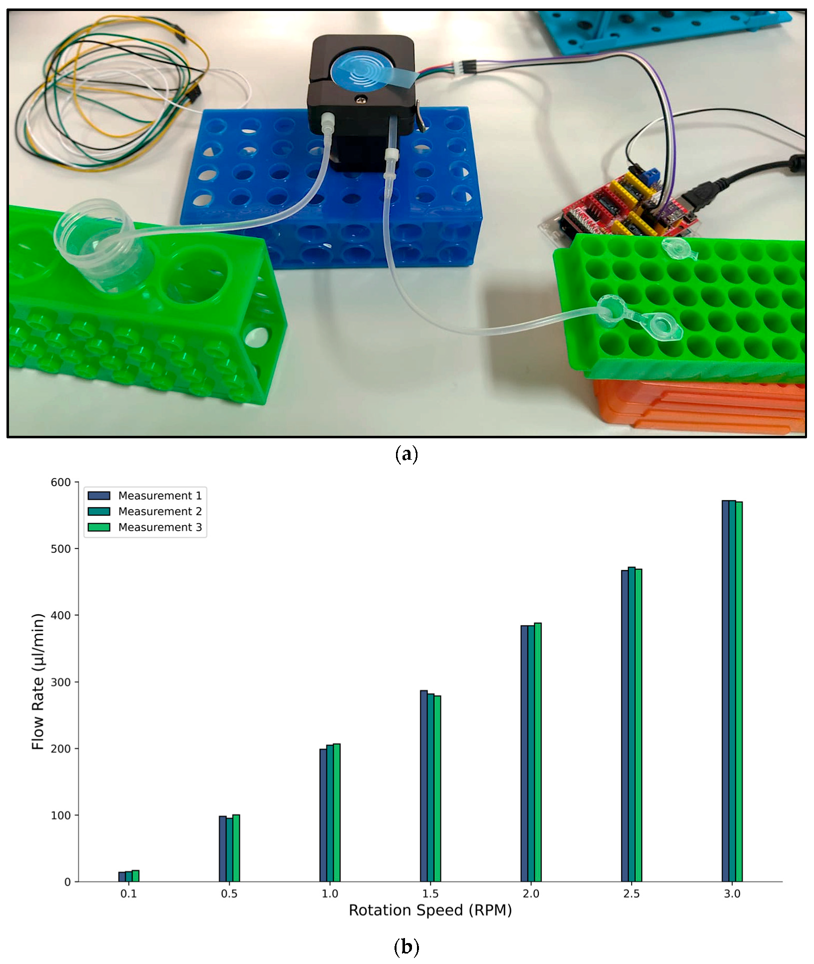
2.2.3. Fluid Flow Rate Determination

The fluid flow rate test was performed to determine the rotational speed (RPM) of the peristaltic pump in microliters per minute (μL/min). The flow rate was determined based on the pump rotation speed of the peristaltic pump and the tubing diameter. The peristaltic pump system was set up to pump distilled water through tubing into an Eppendorf tube. Two different types of silicone tubing were used: a 3.0 mm outer diameter (OD) 1.5 mm inner diameter (ID) tubing, and a 3.8 mm OD tubing, which was located within the pump. The smaller diameter tubes were connected to both ends of the larger diameter tubing. The distilled water was then pumped through the tubing at 0.1, 0.5, 1.0, 1.5, 2.0, 2.5, and 3.0 RPMs for one minute. For each RPM value, the volume of fluid collected in the Eppendorf tube was measured with a micropipette (Brand) and the speed of the pump was calculated in μL/min.

2.2.4. Leakage Test

The leakage test was conducted to assess the integrity of the microfluidic chip and to determine if there were any leaks. A microfluidic chip with the microchannel geometry shown in Figure 2 was used. The medium was passed through the microfluidic chip for 4 h at ~100 µL/min using a peristaltic pump. During the test period, the microfluidic chip was visually inspected for any signs of leakage.

2.2.5. Occlusion Test

The occlusion test was performed to identify potential blockages within a microfluidic chip with the microchannel geometry shown in Figure 2. For this test, 1 mL of medium containing 5 × 10⁵ A549 lung cancer cells was used. Jiang, et al. [41] reported A549 cell diameters of 14.93 μm and 10.59 μm in two distinct microscopy images. The cell-containing medium was passed through the microfluidic chip for 2 h at ~100 µL/min using a peristaltic pump. During the test period, the microfluidic chip was visually inspected for any signs of occlusion.

2.2.6. Conventional and Microfluidic Cell Cultures

The Jurkat cell line, an immortalized T lymphocyte cell line [42], was used in this study. The cell line was at passage number 4, and the culture medium consisted of RPMI 1640 supplemented with 10% FBS and 1% penicillin-streptomycin. Studies in the literature have explored the use of Jurkat cells in both conventional cell culture systems [43,44] and microfluidic devices [45,46]. As widely used in immunology and immuno-oncology research, the Jurkat cell line is also well-suited for microfluidic cell culture studies. For these reasons, Jurkat cells were prioritized in this study.
In conventional cell culture, Jurkat cells were incubated in a suitable volume of medium in a 96-well plate at 37 °C with 5% CO2 for 24 h for cell proliferation. Simultaneously, microfluidic cell culture was also performed. For this, the medium containing Jurkat cells was transferred into a microfluidic chip with one inlet and one outlet (Figure 2) using a peristaltic pump. The recirculating flow in the microfluidic chip was maintained using the peristaltic pump, which operated at a speed of 0.5 RPM. The cells were incubated at 37 °C with 5% CO2 for 24 h. The flow within the chip was maintained throughout the incubation period (Figure 4).

2.2.7. LDH Assay

Cell viability was assessed by lactate dehydrogenase (LDH) release. After 24 h of incubation in both conventional and microfluidic cell cultures, Jurkat cells were removed from the incubator. The Jurkat cells cultured in the microfluidic chip were then transferred to the 96-well plate in which Jurkat cells in conventional cell culture were incubated. After that, the LDH assay was performed using the CyQuant LDH Cytotoxicity Assay Kit (Thermo Fisher Scientific) according to the manufacturer’s instructions. The protocol involved the addition of lysis buffer, incubation, centrifugation, and the addition of reaction mixture and stop solution. After the assay steps were completed, absorbance was measured at 490 nm and 680 nm in a microplate reader (Bmg Labtech CLARIOstar).

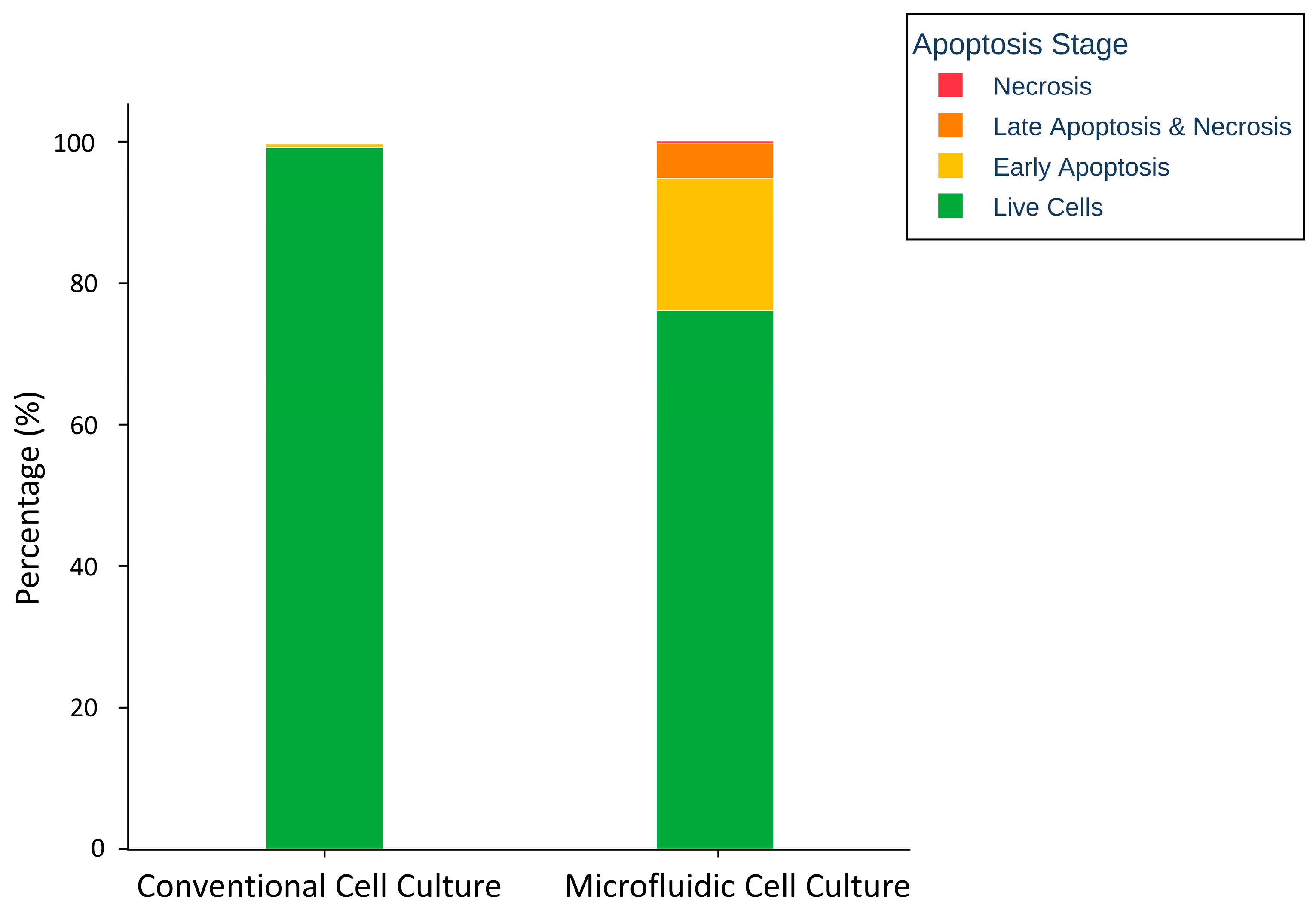
2.2.8. Apoptosis Assay

For the apoptosis assay, the Alexa Fluor 488 Annexin V/Dead Cell Apoptosis Kit containing Alexa® Fluor 488 annexin V and propidium iodide (PI) was used according to the manufacturer’s protocol. Briefly, Jurkat cells in conventional and microfluidic cultures were washed three times with PBS and then transferred into microcentrifuge tubes. The cells were incubated with 5 μL of Annexin V and 1 μL of PI at room temperature for 15 min. Subsequently, 10,000 events were analyzed using a flow cytometer (BD Accuri C6 Plus).

3. Results and Discussion

3.1. Fluid Flow Rate Analysis

The flow rate test was conducted to determine the rotational speed of the pump in μL/min. Distilled water was pumped through the tubing at various RPMs for one minute. For each RPM value, the volume of fluid collected in the Eppendorf tube was measured using a micropipette, and the rotational speed of the pump was calculated in μL/min. To measure the volume of the water collected in the Eppendorf, the following approach was followed. First, the micropipette measurement value was set, and the water in the Eppendorf was drawn. A gap remained in the pipette tip when the water was drawn up. By revolving the plunger of the pipette, the set measurement value was decreased. When the water reached the end of the pipette tip, the volume of liquid was measured, and thus the volume drawn was determined precisely. The results demonstrated that the flow rate of the fluid was directly proportional to the pump speed, and there was a linear relationship between the flow rate and pump speed. Similarly, Ching, et al. [47] reported a linear correlation between peristaltic pump speed (RPM) and flow rate in their study, where they developed two pump variants. The relationship between peristaltic pump speed and flow rate (RPM to μL/min) is shown in Figure 5. Detailed measurements are provided in Table S1.

3.2. Leakage Analysis

The leakage test was conducted to assess the sealing integrity of the microfluidic chip. A microfluidic chip, featuring the microchannel geometry shown in Figure 2, was used, and the medium was pumped through the microfluidic chip for 4 h at ~100 µL/min using a peristaltic pump. As emphasized by Sözmen and Arslan Yildiz [14], the success of a leakage test is strongly dependent on the microfluidic chip fabrication material, along with the dimensions and geometry of its microchannels. Therefore, these parameters were meticulously deliberated during the design of the microfluidic chips used in this study. As a result, no leakage was observed from the microfluidic chip, and it successfully passed the leakage test conducted in this study (Supplementary Figure S6).

3.3. Occlusion Analysis

The occlusion test was performed to identify potential blockages within a microfluidic chip. A microfluidic chip, featuring the microchannel geometry shown in Figure 2, and the medium containing 1 mL of 5 × 10⁵ A549 cells were used. The cell-containing medium was pumped through the microfluidic chip for 2 h at ~100 µL/min using a peristaltic pump. The presence of a blockage in the microfluidic chip was visually inspected with an inverted light microscope (Zeiss) at 20× magnification. As a result, no blockages were observed in the microfluidic chip, and it successfully passed the test conducted in this study (Supplementary Figure S7).

3.4. LDH Assay

Cytotoxicity assays are an important component of in vitro toxicology studies. The LDH assay is one of the most widely used methods for assessing cell viability or cytotoxicity [48]. Lactate dehydrogenase (LDH) is a cytoplasmic enzyme present in all cells [49]. When cells are exposed to a toxic substance, the integrity of their plasma membrane is disrupted, and LDH leaks out of the cells into the cell medium. This is measured spectrophotometrically [50]. The LDH assay is reliable, rapid, and allows for easy interpretation [48].
Jurkat cells were cultured for 24 h at 5% CO2 and 37 °C in both conventional cell culture environment and within the microfluidic chip. Unlike adherent cell types, Jurkat cells are suspension cells that can proliferate without adhering to a surface. Studying suspension cells, like Jurkat cells, in microfluidic environments is essential to better mimic the microenvironment and gain a deeper understanding of the effects of flow [8]. An LDH test was conducted to compare the cell viability of these cultured cells in these two different cell cultures. The integration of flow into the system and the effect of microfluidic cell culture on cell viability were investigated.
The results indicated that the cell viability in the microfluidic cell culture (111.99 ± 7.79%) was higher than that in the conventional cell culture (100 ± 15.80%) (Table S2). Statistical analyses were conducted to evaluate whether this difference was significant. First, the normality of the data and the homogeneity of variances between the two groups were verified using the Shapiro–Wilk and Levene tests, respectively. Later, the t-test results showed that although there was a difference in cell viability between the two groups, this difference was not statistically significant (Figure 6).
The lack of a significant increase could be attributed to the relatively short 24 h culture period. In longer-term cultures, lasting 72 h or more, Jurkat cells may better adapt to the microenvironment provided by the microfluidic system. This could lead to a significant increase in cell viability. Another finding of this study is that, despite using a PMMA microfluidic chip with low gas permeability, Jurkat cells maintained high viability even after 24 h. This viability is believed to stem from oxygen diffusion through the silicone tubing. Incorporating biocompatible and gas-permeable silicone tubes in PMMA microfluidic chips could play a crucial role in facilitating oxygen access and supporting cellular respiration.

3.5. Apoptosis Assay

Apoptosis, or programmed cell death, plays a critical role in various cellular processes [51,52]. Following the initiation of apoptosis, cells undergo a series of biochemical and morphological alterations, such as DNA fragmentation, cell shrinkage, and chromatin condensation. These changes can be assessed through the utilization of diverse analytical techniques [53].
After culturing Jurkat cells in both conventional and microfluidic cell cultures at 5% CO2 and 37 °C for 24 h, an apoptosis test was performed to compare the apoptosis levels in these two different cell culture environments and analyze the effect of the microfluidic culture system. Apoptosis analysis revealed the following percentages in microfluidic culture: 76.1% live cells, 18.7% early apoptosis, 5.0% late apoptosis with necrosis, and 0.3% necrosis. On the other hand, in conventional cell culture, the percentage of living cells was 99.2%, early apoptosis was 0.5%, late apoptosis with necrosis was 0.1%, and necrosis was 0.1%, which was almost negligible (Figure 7). This finding suggests that the cells are exposed to increased mechanical or microenvironmental stress, which induces them to enter the early apoptosis stage.
The results of the LDH and apoptosis analyses indicate that not only did cell proliferation in the microfluidic system increase, but cellular stress also increased. However, despite this increased stress, a large portion of the cells maintained their membrane integrity and continued to proliferate. To effectively reduce cellular stress in these systems, meticulous determination of parameters such as flow rate, channel geometry, and materials used in chip fabrication is essential. Microfluidic systems have the potential to better mimic the in vivo cellular microenvironment, making them valuable in various biomedical applications [54]. The chip fabrication method and peristaltic pump presented in this study can provide experimental design improvements, including precise flow control and channel customization. Consequently, this study has the potential to contribute to the use of microfluidic systems in biomedical applications.

4. Conclusions

In this study, PMMA microfluidic chips were fabricated cost-effectively and simply using laser cutting technology. In addition, an open-source, low-cost peristaltic pump with a user-friendly interface application was constructed. The chip and pump platform was successfully integrated into a microfluidic cell culture application using Jurkat cells suitable for suspension culture. Result from the LDH assay demonstrated that cell viability was higher in the microfluidic chip compared to conventional cell culture. On the other hand, apoptosis analysis showed that the rates of early apoptosis increased in the microfluidic culture, which is most likely a result of mechanical or microenvironmental stress. To mitigate this stress, optimizing flow rates and channel geometries is recommended. Adjustable flow rates and customizable channel designs provided by the chip and pump platform offer flexibility for such improvements. In conclusion, the fabricated microfluidic chip and open-source peristaltic pump are (i) simple, relatively fast, and cost-effective, (ii) customizable according to needs, and (iii) reproducible for small volume cell experiments, and this platform has potential for use in various biomedical research.

Supplementary Materials

The following supporting information can be downloaded at https://www.mdpi.com/article/10.3390/micro5020025/s1; below are the links to the electronic Supplementary Materials. Supplementary File S1. Peristaltic pump application. Microfluidic chip designs. Figure S1: CAD design of the top layers, one inlet–one outlet; Figure S2: CAD design of the middle layers, one inlet–one outlet; Figure S3: Construction of the peristaltic pump system, (a) Schematic of the peristaltic pump system, (b) Peristaltic pump system wiring diagram; Figure S4: Peristaltic pump system: Arduino UNO R3, CNC shield, DRV8825, peristaltic pump module, and power supply; Figure S5: Flow rate test of the peristaltic pump system; (a) flow rate corresponding to each RPM value, (b) The traces depict the average values obtained from three independent measurements, with error bars representing the standard deviation; Figure S6: Leakage test was performed to determine whether there was any leakage in the microfluidic chip; Figure S7: Inverted light microscope image during occlusion test of the microfluidic chip to assess blockage; Table S1: Detailed peristaltic pump speed (RPM to μL/min); Table S2: Comparison of LDH-release–based cell viability in conventional and microfluidic cell cultures; Supplementary S1: The source code of the peristaltic pump system coded in Arduino IDE; Supplementary S2: The source code of the peristaltic pump application.

Author Contributions

Conceptualization, O.P., F.A., M.A.U., M.Y. and A.Y.; Data curation, O.P.; Formal analysis, C.G. and M.Y.; Investigation, M.A.U., M.Y. and A.Y.; Methodology, O.P. and C.G.; Resources, F.A. and A.Y.; Software, M.A.U.; Validation, M.Y. and A.Y.; Writing—original draft, O.P., M.Y. and A.Y.; Writing—review and editing, F.A. and M.A.U. All authors have read and agreed to the published version of the manuscript.

Funding

This study was supported by the Ankara University Scientific Research Projects Coordination Unit (Project Number: 22L0443001).

Institutional Review Board Statement

Not applicable.

Informed Consent Statement

Not applicable. The authors declare that there are no ethical issues related to this work.

Data Availability Statement

All data are available within the article or its Supplementary Information.

Acknowledgments

The authors would like to thank Ankara University Scientific Research Projects Coordination Unit for providing financial support within the scope of this study (Project Number: 22L0443001).

Conflicts of Interest

The authors have no competing interests to declare that are relevant to the content of this article.

References

  1. Weiskirchen, S.; Schröder, S.K.; Buhl, E.M.; Weiskirchen, R. A beginner’s guide to cell culture: Practical advice for preventing needless problems. Cells 2023, 12, 682. [Google Scholar] [CrossRef] [PubMed]
  2. Halldorsson, S.; Lucumi, E.; Gómez-Sjöberg, R.; Fleming, R.M. Advantages and challenges of microfluidic cell culture in polydimethylsiloxane devices. Biosens. Bioelectron. 2015, 63, 218–231. [Google Scholar] [CrossRef] [PubMed]
  3. Young, E.W.; Beebe, D.J. Fundamentals of microfluidic cell culture in controlled microenvironments. Chem. Soc. Rev. 2010, 39, 1036–1048. [Google Scholar] [CrossRef]
  4. Varan, G.; Unal, S. Three-dimensional cell culture methods in infectious diseases and vaccine research. Future Pharmacol. 2023, 3, 48–60. [Google Scholar] [CrossRef]
  5. Kapałczyńska, M.; Kolenda, T.; Przybyła, W.; Zajączkowska, M.; Teresiak, A.; Filas, V.; Ibbs, M.; Bliźniak, R.; Łuczewski, Ł.; Lamperska, K. 2D and 3D cell cultures—A comparison of different types of cancer cell cultures. Arch. Med. Sci. 2018, 14, 910–919. [Google Scholar] [CrossRef]
  6. Saydé, T.; El Hamoui, O.; Alies, B.; Gaudin, K.; Lespes, G.; Battu, S. Biomaterials for three-dimensional cell culture: From applications in oncology to nanotechnology. Nanomaterials 2021, 11, 481. [Google Scholar] [CrossRef]
  7. Yilmazer, A. Cancer cell lines involving cancer stem cell populations respond to oxidative stress. Biotechnol. Rep. 2018, 17, 24–30. [Google Scholar] [CrossRef] [PubMed]
  8. Wu, M.-H.; Huang, S.-B.; Lee, G.-B. Microfluidic cell culture systems for drug research. Lab A Chip 2010, 10, 939–956. [Google Scholar] [CrossRef]
  9. Sattari, A.; Hanafizadeh, P.; Hoorfar, M. Multiphase flow in microfluidics: From droplets and bubbles to the encapsulated structures. Adv. Colloid Interface Sci. 2020, 282, 102208. [Google Scholar] [CrossRef]
  10. İnce, G.T.; Yüksekkaya, M.; Haberal, O.E. Micro-polymerase chain reaction for point-of-care detection and beyond: A review microfluidics and nanofluidics. Microfluid. Nanofluidics 2023, 27, 68. [Google Scholar] [CrossRef]
  11. İçöz, K.; Akar, Ü.; Ünal, E. Microfluidic Chip based direct triple antibody immunoassay for monitoring patient comparative response to leukemia treatment. Biomed. Microdevices 2020, 22, 48. [Google Scholar] [CrossRef] [PubMed]
  12. Battat, S.; Weitz, D.A.; Whitesides, G.M. An outlook on microfluidics: The promise and the challenge. Lab A Chip 2022, 22, 530–536. [Google Scholar] [CrossRef] [PubMed]
  13. Mehling, M.; Tay, S. Microfluidic cell culture. Curr. Opin. Biotechnol. 2014, 25, 95–102. [Google Scholar] [CrossRef] [PubMed]
  14. Sözmen, A.B.; Arslan Yildiz, A. Cost-effective and rapid prototyping of PMMA microfluidic device via polymer-assisted bonding. Microfluid. Nanofluidics 2021, 25, 66. [Google Scholar] [CrossRef]
  15. Niculescu, A.-G.; Chircov, C.; Bîrcă, A.C.; Grumezescu, A.M. Fabrication and applications of microfluidic devices: A review. Int. J. Mol. Sci. 2021, 22, 2011. [Google Scholar] [CrossRef]
  16. Ren, K.; Zhou, J.; Wu, H. Materials for microfluidic chip fabrication. Acc. Chem. Res. 2013, 46, 2396–2406. [Google Scholar] [CrossRef]
  17. Mou, L.; Jiang, X. Materials for microfluidic immunoassays: A review. Adv. Healthc. Mater. 2017, 6, 1601403. [Google Scholar] [CrossRef]
  18. Agha, A.; Dawaymeh, F.; Alamoodi, N.; Abu-Nada, E.; Alazzam, A. Microfluidic fabrication using cyclic olefin copolymer and hydrocarbon solvents. Eur. Polym. J. 2023, 196, 112329. [Google Scholar] [CrossRef]
  19. Agha, A.; Dawaymeh, F.; Alamoodi, N.; Alazzam, A. Enhancing fabrication of hybrid microfluidic devices through silane-based bonding: A focus on polydimethylsiloxane-cyclic olefin copolymer and PDMS-lithium niobate. Appl. Res. 2024, 3, e202300116. [Google Scholar] [CrossRef]
  20. Agha, A.; Abu-Nada, E.; Alazzam, A. Integration of acoustic micromixing with cyclic olefin copolymer microfluidics for enhanced lab-on-a-chip applications in nanoscale liposome synthesis. Biofabrication 2024, 16, 045004. [Google Scholar] [CrossRef]
  21. Guan, Y.; Zhang, H.; Yan, Z.; Wei, X.; Zhang, Z.; Chen, X. Surface Modification of Cyclic-Olefin-Copolymer (COC)-Based Microchannels for the Large-Scale Industrial Production of Droplet Microfluidic Devices. Bioengineering 2023, 10, 763. [Google Scholar] [CrossRef]
  22. Yavuz, C.; Oliaei, S.N.B.; Cetin, B.; Yesil-Celiktas, O. Sterilization of PMMA microfluidic chips by various techniques and investigation of material characteristics. J. Supercrit. Fluids 2016, 107, 114–121. [Google Scholar] [CrossRef]
  23. Kim, M.; Moon, B.-U.; Hidrovo, C.H. Enhancement of the thermo-mechanical properties of PDMS molds for the hot embossing of PMMA microfluidic devices. J. Micromech. Microeng. 2013, 23, 095024. [Google Scholar] [CrossRef]
  24. Trinh, K.T.L.; Thai, D.A.; Chae, W.R.; Lee, N.Y. Rapid fabrication of poly (methyl methacrylate) devices for lab-on-a-chip applications using acetic acid and UV treatment. ACS Omega 2020, 5, 17396–17404. [Google Scholar] [CrossRef]
  25. Chen, Y.; Zhang, L.; Chen, G. Fabrication, modification, and application of poly (methyl methacrylate) microfluidic chips. Electrophoresis 2008, 29, 1801–1814. [Google Scholar] [CrossRef]
  26. Liga, A.; Morton, J.A.; Kersaudy-Kerhoas, M. Safe and cost-effective rapid-prototyping of multilayer PMMA microfluidic devices. Microfluid. Nanofluidics 2016, 20, 164. [Google Scholar] [CrossRef]
  27. Thurgood, P.; Suarez, S.A.; Chen, S.; Gilliam, C.; Pirogova, E.; Jex, A.R.; Baratchi, S.; Khoshmanesh, K. Self-sufficient, low-cost microfluidic pumps utilising reinforced balloons. Lab A Chip 2019, 19, 2885–2896. [Google Scholar] [CrossRef]
  28. Warkiani, M.E.; Khoo, B.L.; Wu, L.; Tay, A.K.P.; Bhagat, A.A.S.; Han, J.; Lim, C.T. Ultra-fast, label-free isolation of circulating tumor cells from blood using spiral microfluidics. Nat. Protoc. 2016, 11, 134–148. [Google Scholar] [CrossRef]
  29. Behrens, M.R.; Fuller, H.C.; Swist, E.R.; Wu, J.; Islam, M.M.; Long, Z.; Ruder, W.C.; Steward, R., Jr. Open-source, 3D-printed peristaltic pumps for small volume point-of-care liquid handling. Sci. Rep. 2020, 10, 1543. [Google Scholar] [CrossRef]
  30. Mohammed, M.; Thurgood, P.; Gilliam, C.; Nguyen, N.; Pirogova, E.; Peter, K.; Khoshmanesh, K.; Baratchi, S. Studying the response of aortic endothelial cells under pulsatile flow using a compact microfluidic system. Anal. Chem. 2019, 91, 12077–12084. [Google Scholar] [CrossRef]
  31. Gazzi, A.; Fusco, L.; Orecchioni, M.; Ferrari, S.; Franzoni, G.; Yan, J.S.; Rieckher, M.; Peng, G.; Lucherelli, M.A.; Vacchi, I.A. Graphene, other carbon nanomaterials and the immune system: Toward nanoimmunity-by-design. J. Phys. Mater. 2020, 3, 034009. [Google Scholar] [CrossRef]
  32. Gurcan, C.; Taheri, H.; Bianco, A.; Delogu, L.G.; Yilmazer, A. A closer look at the genotoxicity of graphene based materials. J. Phys. Mater. 2019, 3, 014007. [Google Scholar] [CrossRef]
  33. Karatay, A.; Erdener, D.; Gürcan, C.; Yildiz, E.A.; Yilmazer, A.; Boyacıoğlu, B.; Unver, H.; Yıldız, M.; Elmali, A. Amino-functionalized nitrogen-doped graphene quantum dots and silver-graphene based nanocomposites: Ultrafast charge transfer and a proof-of-concept study for bioimaging applications. J. Photochem. Photobiol. A Chem. 2022, 426, 113741. [Google Scholar] [CrossRef]
  34. Orecchioni, M.; Bordoni, V.; Fuoco, C.; Reina, G.; Lin, H.; Zoccheddu, M.; Yilmazer, A.; Zavan, B.; Cesareni, G.; Bedognetti, D. Toward High-Dimensional Single-Cell Analysis of Graphene Oxide Biological Impact: Tracking on Immune Cells by Single-Cell Mass Cytometry. Small 2020, 16, 2000123. [Google Scholar] [CrossRef]
  35. Fusco, L.; Gazzi, A.; Shuck, C.E.; Orecchioni, M.; Ahmed, E.I.; Giro, L.; Zavan, B.; Yilmazer, A.; Ley, K.; Bedognetti, D. V4C3 MXene immune profiling and modulation of T cell-dendritic cell function and interaction. Small Methods 2023, 7, 2300197. [Google Scholar] [CrossRef]
  36. Fusco, L.; Gazzi, A.; Giro, L.; Schefer, R.B.; D’Almeida, S.M.; Cagliani, R.; Zoccheddu, M.; Uyar, R.; Besbinar, Ö.; Çelik, D. Nanoplastics: Immune Impact, Detection, and Internalization after Human Blood Exposure by Single-Cell Mass Cytometry. Adv. Mater. 2024, 37, e2413413. [Google Scholar] [CrossRef]
  37. Asghar, W.; Yuksekkaya, M.; Shafiee, H.; Zhang, M.; Ozen, M.O.; Inci, F.; Kocakulak, M.; Demirci, U. Engineering long shelf life multi-layer biologically active surfaces on microfluidic devices for point of care applications. Sci. Rep. 2016, 6, 21163. [Google Scholar] [CrossRef]
  38. Gale, B.K.; Jafek, A.R.; Lambert, C.J.; Goenner, B.L.; Moghimifam, H.; Nze, U.C.; Kamarapu, S.K. A review of current methods in microfluidic device fabrication and future commercialization prospects. Inventions 2018, 3, 60. [Google Scholar] [CrossRef]
  39. Epilog Laser. Owner’s Manuals. 5 June 2023. Available online: https://www.epiloglaser.com/support/laser-manuals/ (accessed on 15 March 2025).
  40. Naher, S.; Orpen, D.; Brabazon, D.; Poulsen, C.; Morshed, M. Effect of micro-channel geometry on fluid flow and mixing. Simul. Model. Pract. Theory 2011, 19, 1088–1095. [Google Scholar] [CrossRef]
  41. Jiang, R.D.; Shen, H.; Piao, Y.-j. The morphometrical analysis on the ultrastructure of A549 cells. Rom. J. Morphol. Embryol 2010, 51, 663–667. [Google Scholar]
  42. Im, D.J.; Jeong, S.-N. Transfection of Jurkat T cells by droplet electroporation. Biochem. Eng. J. 2017, 122, 133–140. [Google Scholar] [CrossRef]
  43. Vashishtha, S.; Nazarali, A.; Dimmock, J. Application of fluorescence microscopy to measure apoptosis in Jurkat T cells after treatment with a new investigational anticancer agent (NC 1213). Cell. Mol. Neurobiol. 1998, 18, 437–445. [Google Scholar] [CrossRef]
  44. Zamorina, S.; Khramtsov, P.; Rayev, M.; Timganova, V.; Bochkova, M.; Nechaev, A.; Shunkin, E.; Khaziakhmatova, O.; Malaschenko, V.; Litvinova, L. Graphene oxide nanoparticels interaction with Jurkat cell line in Cell-IQ system. Dokl. Biochem. Biophys. 2021, 501, 438–443. [Google Scholar] [CrossRef]
  45. Metto, E.C.; Evans, K.; Barney, P.; Culbertson, A.H.; Gunasekara, D.B.; Caruso, G.; Hulvey, M.K.; Fracassi da Silva, J.A.; Lunte, S.M.; Culbertson, C.T. An integrated microfluidic device for monitoring changes in nitric oxide production in single T-lymphocyte (Jurkat) cells. Anal. Chem. 2013, 85, 10188–10195. [Google Scholar] [CrossRef]
  46. Lee, K.; Kim, S.-E.; Doh, J.; Kim, K.; Chung, W.K. User-friendly image-activated microfluidic cell sorting technique using an optimized, fast deep learning algorithm. Lab A Chip 2021, 21, 1798–1810. [Google Scholar] [CrossRef]
  47. Ching, T.; Vasudevan, J.; Tan, H.Y.; Lim, C.T.; Fernandez, J.; Toh, Y.-C.; Hashimoto, M. Highly-customizable 3D-printed peristaltic pump kit. HardwareX 2021, 10, e00202. [Google Scholar] [CrossRef]
  48. Fotakis, G.; Timbrell, J.A. In vitro cytotoxicity assays: Comparison of LDH, neutral red, MTT and protein assay in hepatoma cell lines following exposure to cadmium chloride. Toxicol. Lett. 2006, 160, 171–177. [Google Scholar] [CrossRef]
  49. Kumar, P.; Nagarajan, A.; Uchil, P.D. Analysis of cell viability by the lactate dehydrogenase assay. Cold Spring Harb. Protoc. 2018, 2018, pdb.prot095497. [Google Scholar] [CrossRef]
  50. Han, X.; Gelein, R.; Corson, N.; Wade-Mercer, P.; Jiang, J.; Biswas, P.; Finkelstein, J.N.; Elder, A.; Oberdörster, G. Validation of an LDH assay for assessing nanoparticle toxicity. Toxicology 2011, 287, 99–104. [Google Scholar] [CrossRef]
  51. Koopman, G.; Reutelingsperger, C.; Kuijten, G.; Keehnen, R.; Pals, S.; Van Oers, M. Annexin V for flow cytometric detection of phosphatidylserine expression on B cells undergoing apoptosis. Blood 1994, 84, 1415–1420. [Google Scholar] [CrossRef]
  52. Sgonc, R.; Gruber, J. Apoptosis detection: An overview. Exp. Gerontol. 1998, 33, 525–533. [Google Scholar] [CrossRef] [PubMed]
  53. Mustafa, M.; Ahmad, R.; Tantry, I.Q.; Ahmad, W.; Siddiqui, S.; Alam, M.; Abbas, K.; Moinuddin Hassan, M.I.; Habib, S. Apoptosis: A Comprehensive Overview of Signaling Pathways, Morphological Changes, and Physiological Significance and Therapeutic Implications. Cells 2024, 13, 1838. [Google Scholar] [CrossRef] [PubMed]
  54. Wu, Q.; Liu, J.; Wang, X.; Feng, L.; Wu, J.; Zhu, X.; Wen, W.; Gong, X. Organ-on-a-chip: Recent breakthroughs and future prospects. Biomed. Eng. Online 2020, 19, 9. [Google Scholar] [CrossRef] [PubMed]
Figure 1. Schematic representation for simple prototyping of PMMA microfluidic chip.
Micro 05 00025 g001
Figure 2. Assembled microfluidic chip with one inlet and one outlet.
Micro 05 00025 g002
Figure 3. User interface of the peristaltic pump application, which features a user-friendly design that enables the control of multiple peristaltic pumps together.
Micro 05 00025 g003
Figure 4. Jurkat cells were incubated in conventional cell culture and microfluidic cell cultures (96-well plate and microfluidic chip) at 37 °C with 5% CO2 for 24 h.
Micro 05 00025 g004
Figure 5. The flow rate test was conducted to determine the rotational speed of the pump in μL/min. (a) The test was conducted with n = 3 replicates, and the distilled water volume passed through the pump over one minute was recorded for each RPM value. (b) The pump can dispense specified liquid volumes with high consistency and reliability. The histogram illustrates the flow rates of distilled water at three distinct measurements across a range of rotation speeds.
Micro 05 00025 g005
Figure 6. Cell viability of Jurkat cells in conventional and microfluidic cell cultures. The experiment was conducted with n = 5 replicates for each cell culture. No statistically significant difference was observed between the two groups (p > 0.05). Error bars represent the standard deviation.
Micro 05 00025 g006
Figure 7. Apoptosis assay results of Jurkat cells in conventional and microfluidic cell cultures.
Micro 05 00025 g007
Disclaimer/Publisher’s Note: The statements, opinions and data contained in all publications are solely those of the individual author(s) and contributor(s) and not of MDPI and/or the editor(s). MDPI and/or the editor(s) disclaim responsibility for any injury to people or property resulting from any ideas, methods, instructions or products referred to in the content.

