1. Introduction
Impinging jets are widely used for their high heat transfer capabilities, allowing them to achieve very high local heat transfer coefficients [
1,
2]. This makes them essential in applications like cooling turbine blades, managing heat in electronic devices, and handling surfaces exposed to intense heat flux. In addition to their strong thermal performance, impinging jets also display complex acoustic and aero-acoustic behaviors that arise from the interaction between the jet and the surface it strikes [
3,
4,
5]. These acoustic and flow instabilities can directly influence the thermal and dynamic characteristics of the jet [
6,
7,
8,
9,
10,
11,
12,
13,
14,
15,
16,
17,
18]. Rectangular impinging jets are often preferred over circular ones because they provide even more cooling and better mixing. Their performance depends on several factors, including the nozzle geometry, the distance between the jet and the target surface, the Reynolds number, and the roughness and material of the wall [
13,
19,
20]. Studies have shown that rectangular nozzles with high aspect ratios can reach wider cooling coverage and better overall efficiency. For instance, a rectangular orifice with an aspect ratio of five was found to provide much more uniform cooling, covering an area over 14 times larger than the nozzle’s exit area. This improvement comes from stronger lateral spreading of the jet and better disruption of the boundary layer. In addition, modifying the nozzle shape to lobed or chamfered designs can boost local heat transfer by 16–30%, enhancing cooling performance without any pressure losses. Moreover, using different grid shapes at the nozzle exit can also affect turbulence and flow distribution, further improving the system’s thermal performance [
21,
22,
23,
24]. The impact distance is commonly expressed using a dimensionless spacing ratio, typically denoted as H/D, where H represents the nozzle-to-plate distance and D is the jet diameter (or hydraulic diameter for non-circular jets). Alternatively, some studies use L/H, where L denotes the nozzle-to-plate distance and H is the characteristic height of the non-circular jet. The impact distance has a major impact on performance. When the spacing is small (H/D ≈ 2), the jet strikes the surface more forcefully, creating stronger turbulence and higher heat transfer. At larger spacings (H/D ≈ 4), the flow becomes more stable, but heat transfer in the stagnation region decreases. These variations in H/D directly influence the flow behavior, which in turn affects the overall heat transfer efficiency on the target surface [
23,
25]. Jet inclination also plays an important role in cooling performance. A perpendicular (90°) jet provides the strongest impact and maximizes convective heat transfer, while tilted or swirling jets help spread the cooling more evenly across the surface. For instance, a jet tilted at 45° can reduce natural convective heat loss by about 4.19%. Tilting a swirling jet can also eliminate poorly cooled “dead zones” on the target surface. The advantages of tilting are most noticeable near the jet’s impact area, typically within three jet diameters. Although increasing jet velocity generally enhances cooling, this improvement becomes less significant when the Reynolds number exceeds 18,000 for tilted jets [
26,
27,
28,
29]. The surface modification affects the impingement cooling enhancement. Microstructures, grooves, and fins promote secondary flow and turbulence near the wall, improving local heat transfer. For example, adding an elliptical pin fins to the surface can increase the Nusselt number by 47–54%, and the presence of radial microgrooves can outperform other geometries under high heat flux conditions [
30,
31,
32,
33]. Coatings and magnetic fluids can also add a positive impact; a ferrofluid coating can raise the heat transfer by 32% by inducing micro-vortices within the layer [
34,
35]. On the other hand, pointing a jet at a slightly angled surface (around 15 degrees) creates helpful swirls that pull heat away more effectively and improve heat transfer [
36,
37].
Recent studies focused on active and hybrid methods to enhance the heat transfer [
17]. Passive systems include annular [
38,
39], swirl [
40,
41] and sweeping jets [
42,
43], while active techniques involve synthetic [
44,
45] and pulsed jets [
46,
47]. Hybrid systems added significant potential for further improvement in heat transfer, these systems combine self-exciting jets with mechanisms like fluid diodes [
48], modified surfaces [
49,
50], nanofluids [
51,
52,
53], or piezoelectric fans [
54,
55,
56].
To better understand the appearance of primary and secondary peaks in the mean Nusselt number distribution, several studies have been conducted [
57,
58]. The primary peak is generally attributed to the increase in turbulence intensity caused by the impingement of the jet shear layer on the surface. In addition, many researchers have investigated the origin of the secondary peak, which remains less clear. Most studies agree that the primary heat transfer enhancement in jet impingement is mainly associated with the impact of primary vortical structures [
59,
60,
61,
62].
Previous studies on heat transfer in impinging jets have shown a strong link between heat transfer behavior and turbulence dynamics. Two main approaches can be identified: the enhancement of heat transfer through acoustic excitation, and the control of acoustic emissions by heating or cooling the impingement surface [
63,
64,
65,
66,
67,
68,
69].
Experimental studies using PIV and heat transfer measurements have shown that flow unsteadiness and vortex formation significantly influence the heat transfer characteristics of impinging jets. For example, experiments on pulsating impinging jets demonstrated that vortex generation and enhanced mixing can lead to noticeable heat transfer enhancement compared with steady jets due to the dominance of large coherent vortices and the associated spectral peaks, and these findings are therefore consistent with the flow–structure mechanisms [
70]. In addition, previous experimental investigations reported that pulsation or acoustic excitation can modify the vortex dynamics and increase turbulence intensity in the wall jet region, which promotes thermal mixing and improves heat transfer performance [
71].
Despite the extensive literature on impinging jets, limited attention has been devoted to the coupled interaction between coherent flow structures, acoustic dynamics, and convective heat transfer at closely spaced Reynolds numbers. In particular, the mechanism by which minor variations in Reynolds number reorganize modal energy distribution and influence thermal performance remains insufficiently clarified. The present experimental study addresses this gap by examining a rectangular jet impinging on a heated plate at Re = 3550 and 3750, corresponding to only a slight increase in outlet velocity. By combining Particle Image Velocimetry (PIV), Proper Orthogonal Decomposition (POD), acoustic measurements, and infrared thermography, this work establishes a quantitative link between modal energy redistribution, aero-acoustic cross-correlation, and Stanton number enhancement. The results demonstrate that a shift toward dominant-mode energy concentration (approaching 20% of the fluctuating energy) and strong flow–acoustic coupling governs the observed improvement in convective heat transfer while simultaneously reducing the acoustic intensity of the jet. This integrated framework provides new mechanistic insight into how coherent vortex organization regulates thermal efficiency in impinging jet systems.
2. Materials and Methods
2.1. Experimental Setup
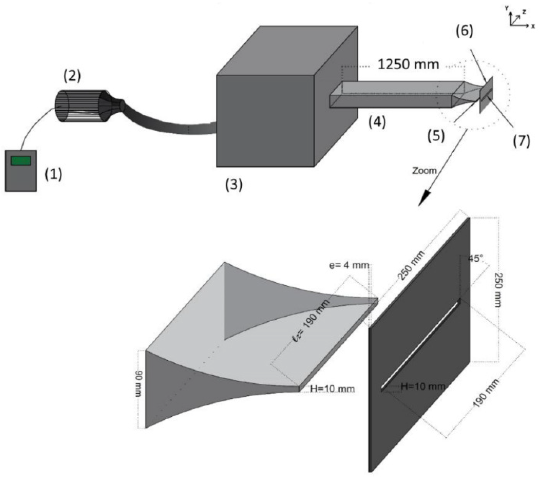
The experimental apparatus shown in
Figure 1 consisted of a rectangular nozzle aligned toward a heated slotted aluminum plate. A frequency chopper (1) was used to regulate the compressor (2) that supplied the airflow, achieving up to 33 m/s (Mach 0.1). The flow passes through a damping chamber (3) equipped with three metal grids to minimize acoustic noise and turbulence, then conditioned in a 1.25 m duct (4) of 190 × 90 mm cross-section containing honeycombs for uniformity before reaching (5) the converging nozzle (190 × 10 mm). The impinged (6) plate (250 × 250 × 4 mm) included a 45°-slotted bevel (7) aligned with the nozzle exit. The ambient air temperature was maintained between 18 and 20 °C.
A precision linear positioning system (ISEL MS 200 HT2 Direkt, manufactured by isel Germany GmbH, Eichenzell, Germany) was used to accurately control the nozzle-to-plate spacing. The rectangular nozzle height was fixed at H = 10 mm, taken as the characteristic length of the jet. The impingement distance was set to L = 4 H, a spacing selected to promote strong jet–plate interaction and potential resonance effects. The jet impinged on a 250 × 250 mm heated plate, providing sufficient surface area to capture the spatial development of the thermal field. The spanwise width (Lz = 190 mm) resulted in an aspect ratio of Lz/H = 19, ensuring a quasi-two-dimensional flow structure. Two closely spaced Reynolds numbers, Re = 3550 and Re = 3750, were investigated by adjusting the exit velocities to 5.5 m/s and 5.75 m/s, respectively. The Reynolds numbers were selected to investigate the flow behavior in the transitional regime of the impinging jet. These operating conditions were chosen because preliminary measurements indicated noticeable variations in the flow–acoustic interaction and heat-transfer characteristics within this range. Studying two close Reynolds numbers allows the influence of slight changes in flow inertia on vortex dynamics, acoustic response, and heat transfer performance to be examined. The reported dominant frequencies and heat transfer enhancement levels are specific to the present geometric configuration and operating conditions.
2.2. Measurement Techniques
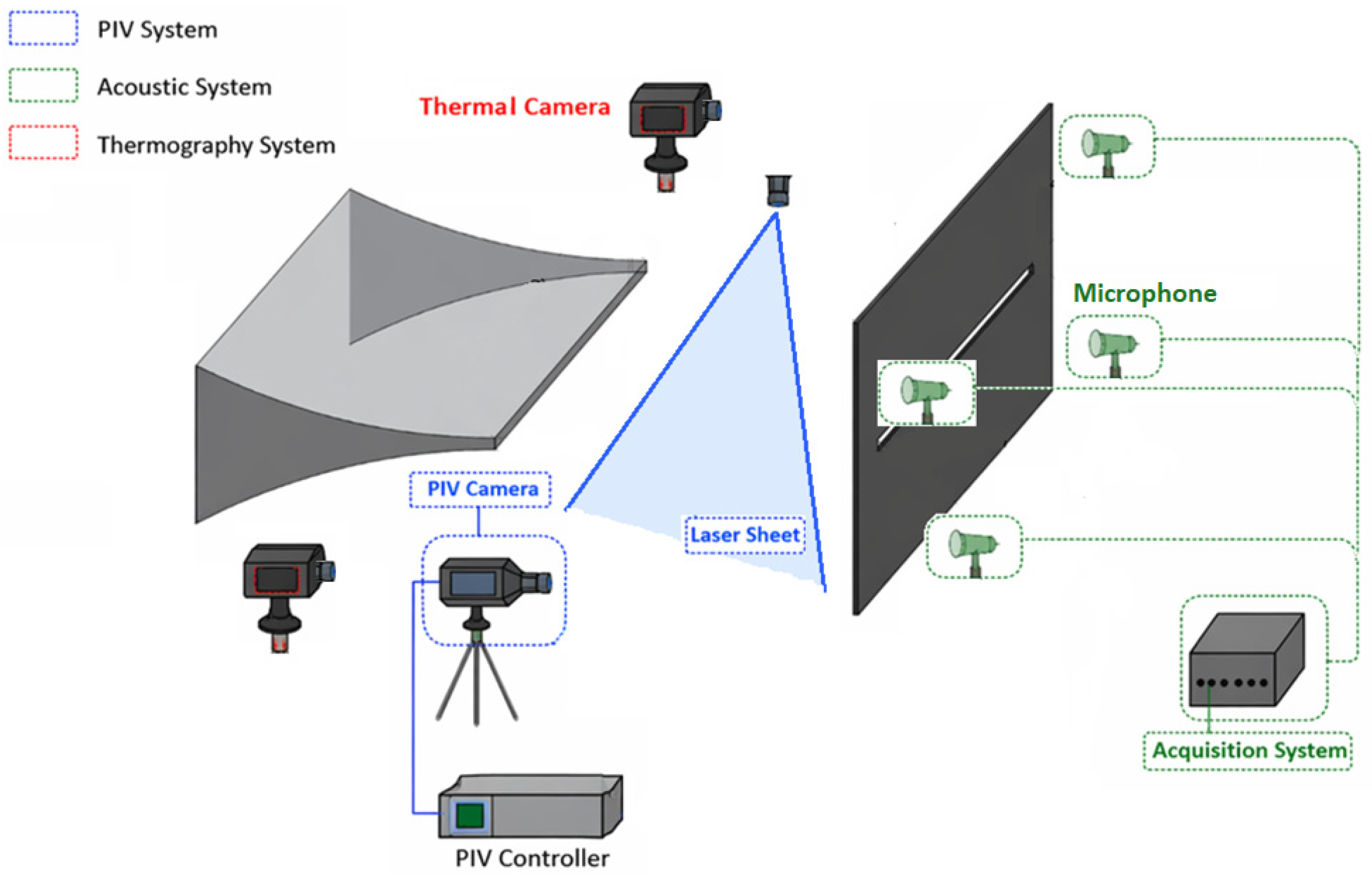
To show the jet’s behavior characteristic, three synchronized measurements (
Figure 2) were taken: temperature, velocity, and acoustic pressure. Each technique was selected to provide high spatial and temporal resolution, ensuring accurate capture of the relevant physical phenomena.
2.2.1. Infrared Thermography
For the thermal measurement, two Xenics Gobi-640-GigE cameras manufactured by Xenics NV (Leuven, Belgium) (640 × 480 pixels) were used to monitor the entire plate surface. Each camera is equipped with an uncooled micro-bolometer (a-Si) sensor featuring greater than 99% operating efficiency (rolling shutter). Operating within the 8–14 μm range, they provided 0.5 mm spatial and 0.05 °C thermal resolution, acquiring data at 50 Hz. Prior to the experiments, the infrared camera was calibrated using a reference temperature source to ensure the accuracy of the temperature measurements. The emissivity of the heated plate surface was carefully considered in the thermographic analysis. To minimize emissivity-related errors, the surface was coated with a high-emissivity matte black paint, and an emissivity value of ε ≈ 0.95 was used during the temperature acquisition and post-processing. This procedure ensures reliable temperature measurements and reduces potential reflection effects from the surrounding environment. The uncertainty in heat transfer coefficient measurements was estimated at ±1.35% and ±1.28% for Re = 3550 and Re = 3750, respectively.
2.2.2. Particle Image Velocimetry (PIV)
The velocity field between the nozzle exit and the heated plate was computed using a two-dimensional PIV system [
72]. In this study, the PIV system consists of three main components: seeding particles, a laser sheet, and cameras. Very fine olive oil droplets (0.1–0.2 μm) were used to seed the flow, while a dual-cavity Litron Nd:YLF laser (Litron Lasers Ltd., Rugby, UK) (30 mJ per pulse, 1 kHz, 527 nm) illuminated the measuring area. The laser sheet thickness was adjustable, with a minimum of 0.5 mm to achieve high spatial resolution. A high-speed Phantom V711 camera (Vision Research, Inc., Wayne, NJ, USA) (1200 × 800 pixels) were used to record images. It was equipped with a Tokina 100 mm macro lens (Kenko Tokina Co., Ltd., Tokyo, Japan) with an adjustable aperture (up to f/2.8), providing a good balance between image detail and coverage. The final sub-image consists of 32 × 32-pixel interrogation windows with 75% overlap. Moreover, image post-processing was applied, where vectors with a peak ratio lower than 1.5 were removed. This resulted in some gaps that were subsequently filled using bilinear interpolation. With this processing configuration, the spatial resolution of the velocity field was adequate to capture the main coherent structures of the impinging jet. The uncertainty in velocity measurements was estimated at ±2.13% and ±1.98% of the jet exit velocity for Re = 3550 and Re = 3750, respectively.
2.2.3. Acoustic Pressure Measurements
To study the interaction between the flow behavior and acoustic resonance, four Brüel and Kjær Type 4189 microphones (manufactured by Hottinger Brüel & Kjær in Nærum, Denmark) (20 Hz–20 kHz range) were installed near the plate to record the acoustic pressure. Based on the manufacturer specifications and calibration accuracy, the uncertainty of the sound pressure level (SPL) measurements is estimated to be approximately ±0.7 dB. The data were collected using an NI PXIe-4496 acquisition system (National Instruments, Austin, TX, USA) and analyzed using a Fast Fourier Transform (FFT) to identify the main resonance frequencies.
2.2.4. Heated Plate
The aluminum plate was heated using two Omega-Lux SRMU020409-P strip heaters (Norwalk, CT, USA) (90 W each) installed on the rear surface of the plate and controlled through a LabVIEW-based power supply. This configuration ensured a stable and nearly uniform heating of the target surface. The plate temperature was stabilized at 65 °C before initiating the jet impingement to ensure steady thermal conditions. The local surface heat flux was measured using four thin-film heat flux sensors (Hukseflux FHF05, manufactured in Delft, The Netherlands) installed on the heated plate. The sensors determine the heat flux from the measured voltage output divided by the calibration sensitivity provided by the manufacturer. To ensure that the measurements correspond primarily to the convective heat transfer generated by the impinging jet, a reflective gold layer was applied on the sensor surface to block incident thermal radiation. All sensors and cameras were synchronized through a common trigger to ensure time-resolved correlation between the velocity, acoustic, and thermal measurements.
2.2.5. Data Synchronization and Processing
The temperature distribution over the slotted plate was measured using two Xenics infrared cameras manufactured by Xenics NV (Leuven, Belgium), positioned to capture the upper and lower parts of the surface. Both cameras were operated through the Xeneth software (Xeneth software version 2.7.1.537 (64-bit), developed by Xenics), which allowed calibration, zoom and focus adjustments, histogram analysis, and pixel-based temperature measurements. The emissivity of the plate surface was considered during the thermographic measurements. To minimize reflection errors, the surface of the plate was coated with a high-emissivity matte black paint (ε ≈ 0.95). The plate was uniformly heated with self-adhesive heating bands powered by a California Instruments 1U Asterion AC/DC supply (California Instruments, San Diego, CA, USA). The heating system was controlled via LabVIEW (version 2018) through an NI PXIe-1073 chassis (manufactured by National Instruments (NI), Austin, TX, USA) equipped with an NI PXIe-6738 data acquisition (analog output) card (manufactured by National Instruments (NI), Austin, TX, USA). Before the experiments, a voltage–temperature calibration was performed, showing that an input of 80 V produced a steady-state plate temperature of about 65 °C. During testing, the plate was first heated to the target temperature and then cooled by the impinging jet until thermal steady state was reached. The heating remained active throughout the measurements to maintain thermal stability. Temperature data were saved in CSV format using Xeneth and later processed in MATLAB (version R2019b) to create high-resolution thermal maps of both the upper and lower surfaces of the slotted plate.
2.3. Data Analysis Methods
To clarify the relationship between the flow dynamics and heat transfer behavior, several advanced data analysis techniques were applied.
2.3.1. Heat Transfer Evaluation
The local heat transfer coefficient was calculated from the surface temperature distribution obtained by IR thermography. The local Stanton (St) was evaluated as:
where
H represents the convective heat transfer coefficient,
ρ is the air density,
Cp is the specific heat of air (T = TN = 26 °C),
Uout denotes the jet exit velocity.
To enable a consistent comparison of heat transfer performance under different flow conditions, the convective heat transfer coefficient was expressed in dimensionless form using the Stanton number. This parameter indicates how effectively the impinging jet transfers heat to the surrounding flow. By analyzing the spatial distribution of the Stanton number, the influence of coherent vortical structures and acoustic resonances on local cooling behavior can be identified, while its overall average value provides insight into the thermal stability and efficiency of the jet system.
The heat flux supplied to the heated plate was maintained constant during the experiments in order to ensure comparable thermal boundary conditions for all operating cases. Keeping a constant heat flux is a common approach in jet impingement heat transfer studies, as it allows the influence of flow parameters, such as the Reynolds number, on the heat transfer performance to be evaluated independently of variations in the thermal input. The heat transfer coefficient H is obtained from the heat flux Q and the temperature difference between the surface and the fluid:
where
Qconv: heat flux convection (Q = 472 W/m2 for Re = 3550 and 475 W/m2 for Re = 3750).
TP: the plate temperature.
TN: the nozzle temperature.
2.3.2. Proper Orthogonal Decomposition (POD)
The PIV velocity fields were analyzed using POD to identify the dominant energetic patterns within the flow. This technique decomposes the velocity fluctuations into a set of independent spatial modes and their corresponding time-dependent coefficients, allowing the identification of coherent structures that influence the momentum and the heat transfer. In the present study, 1000 instantaneous velocity fields were used, and a convergence check was performed by verifying that the energy distribution of the leading POD modes remained unchanged when different numbers of snapshots were considered. To apply this method, the velocity snapshots were arranged into the snapshot matrix:
where each column corresponds to the spatial velocity field at time t
m. POD was then performed using the Singular Value Decomposition (SVD):
where
U contains the spatial POD modes,
V contains the temporal coefficients,
Σ is a diagonal matrix of singular values.
The energy content associated with each mode was quantified as:
where
σi is the
i-th singular value and N is the total number of modes. This normalization ensures that the sum of the modal energies equals unity.
The number of retained modes was selected based on the cumulative energy criterion. In the present study, the truncation level was chosen such that the retained modes capture 99% of the total fluctuating kinetic energy of the flow. The corresponding number of modes was therefore determined from the condition
the temporal coefficients associated with the retained modes were obtained by projecting the fluctuating velocity field onto the spatial modes
where ϕ
i represents the spatial structure of the
i-th POD mode and a
i(t) denotes the corresponding temporal coefficient.
This decomposition made it possible to identify the dominant coherent structures and their temporal evolution, allowing a direct comparison of flow organization at different Reynolds numbers [
73].
High-resolution Particle Image Velocimetry (PIV) was employed to obtain instantaneous and time-averaged velocity fields. However, mean flow analysis alone is insufficient to reveal the coherent structures responsible for tonal generation and heat transfer modulation. Therefore, Proper Orthogonal Decomposition (POD) was applied to extract the most energetic coherent structures and quantify their contribution to the fluctuating kinetic energy. The temporal coefficients of the dominant modes were further analyzed to investigate their coupling with the acoustic signal through cross-correlation analysis. This approach enables identification of energy-dominant flow structures and assessment of their synchronization with the acoustic field, providing insight into the mechanisms governing vortex organization and convective heat transfer enhancement.
2.3.3. Turbulance Kinetic Energy (TKE)
The turbulent kinetic energy (TKE) was calculated from the velocity fluctuations obtained from the PIV measurements in order to quantify the intensity of turbulent motion in the jet flow. The instantaneous velocity components were decomposed into mean and fluctuating parts, and the turbulent kinetic energy was computed as
where u’ and v’ represent the fluctuating components of the velocity in the streamwise and transverse directions, respectively. The velocity fluctuations were obtained by subtracting the time-averaged velocity field from the instantaneous velocity measurements. The resulting TKE fields were used to identify regions of strong turbulent activity and to examine their relation with the coherent structures observed in the flow [
73].
3. Results
3.1. Flow Analysis
Microphones
Impinging jets often produce tonal noise, which can become stronger when the jet hits a slotted plate, as in this study.
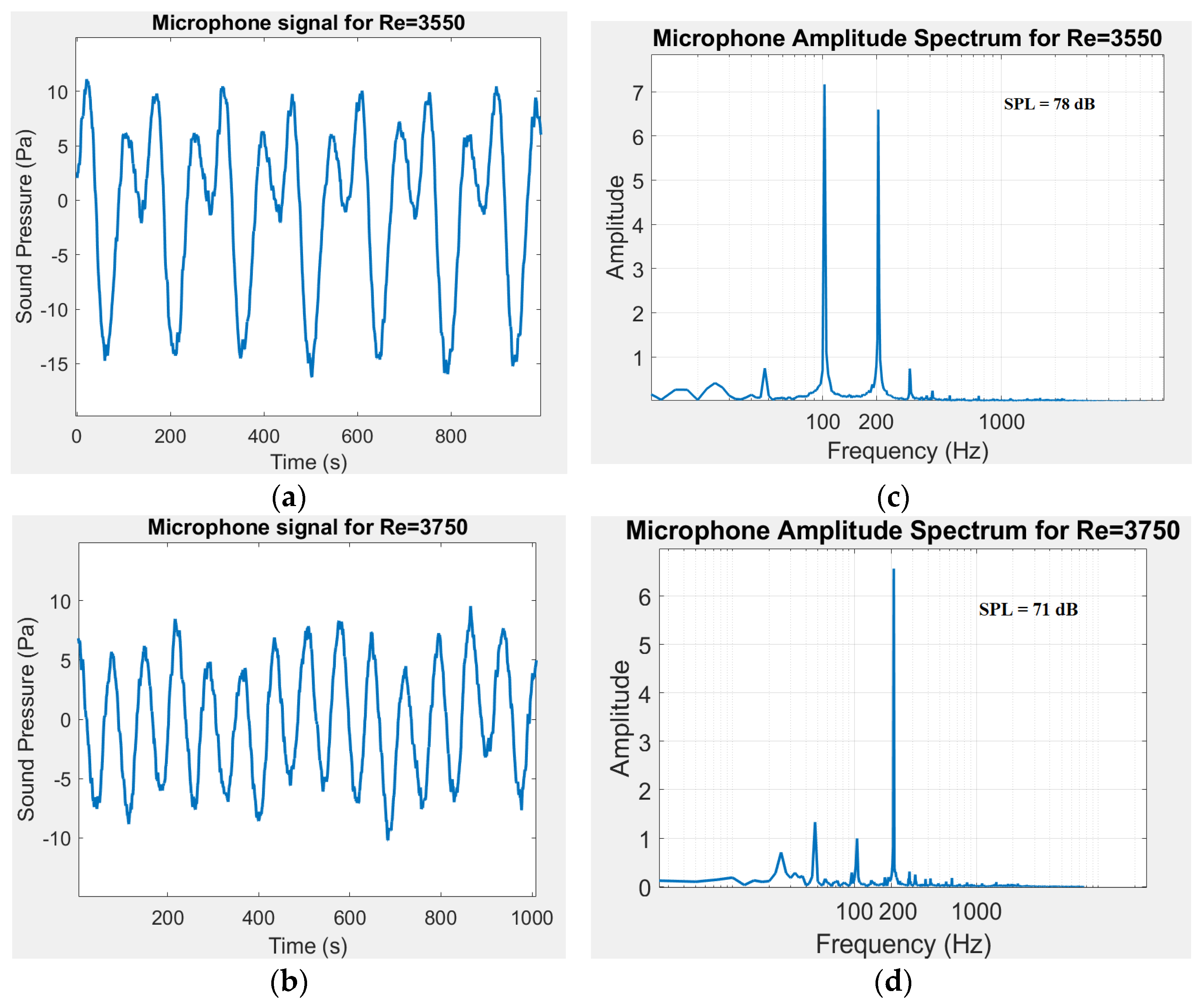
Figure 3 shows the frequency and spectrum representation for the both Re. For Re = 3550, the acoustic spectrum showed two main tones: F
1 = 105 Hz and its harmonic F
2 = 202.5 Hz (2F
1). The overall sound pressure level reached approximately 78 dB.
At Re = 3750, only one main frequency F1 = 210 Hz appears and the overall sound pressure decrease to 71 dB.
3.2. Mean and Instantaneous Flow Field
The PIV velocity fields clearly show how the jet interacts with the wall and how vortices form and develop in the impingement zone. For both Reynolds numbers, the jet has a well-defined stagnation region where the flow hits the wall with strong normal momentum and spreads only slightly sideways. Beyond this zone, the flow turns into a thin wall jet that moves along the surface.
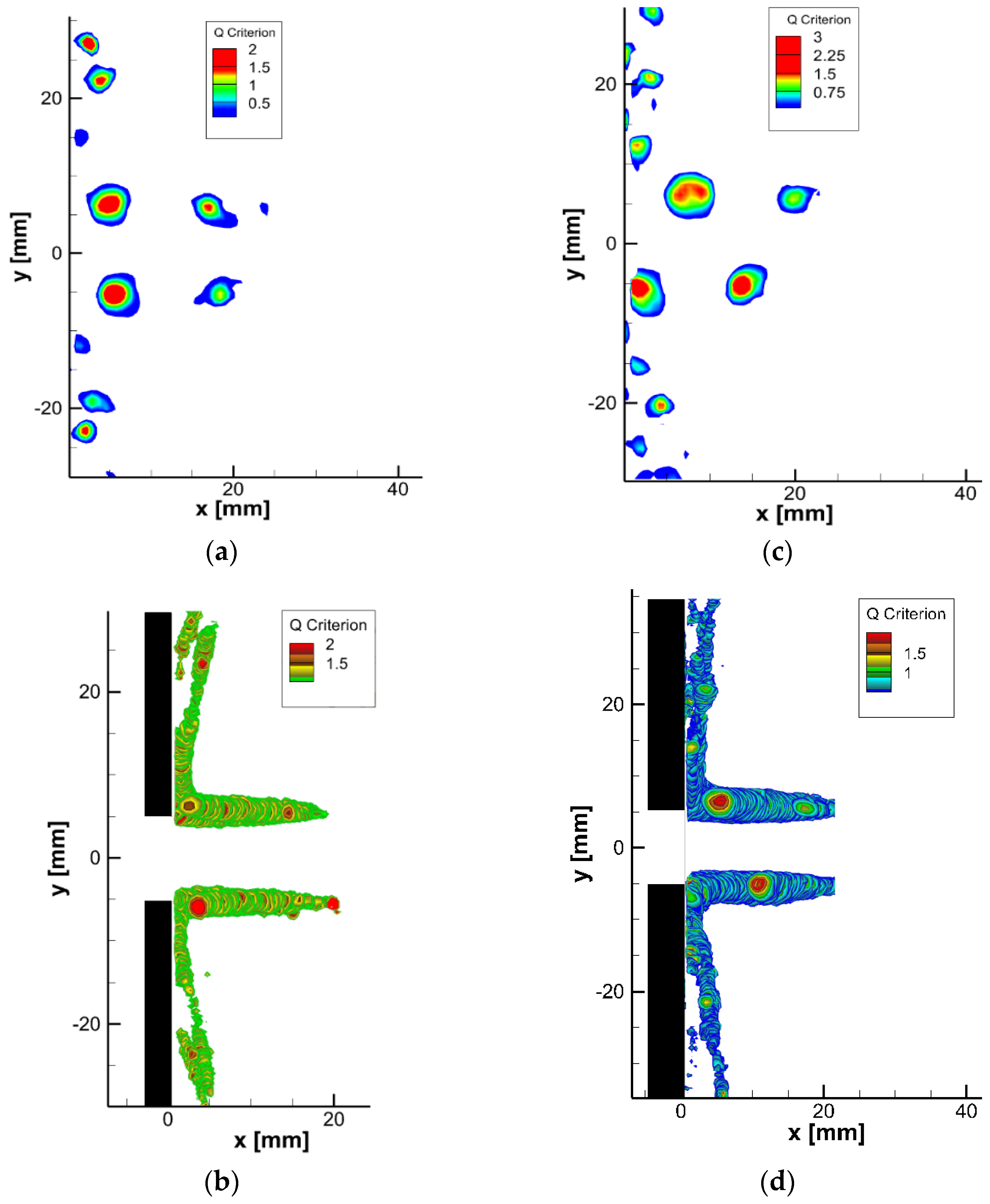
To visualize the main vortex structures, the Q-criterion was applied at both flow conditions. This revealed clear differences between the two Reynolds numbers. At Re = 3550, the main vortex changes direction as it strikes the plate, while smaller secondary vortices appear closer to the wall (
Figure 4a). At Re = 3750, vortices form later along the jet path, shifting the regions of high Q-value farther downstream (
Figure 4c). These results agree with previous studies showing that the distance between the nozzle and plate strongly affects vortex formation and turbulence in impinging jets [
74].
At Re = 3550, the flow produced symmetrical vortices that stayed organized as they moved toward the slotted plate. When they reached the surface, two main behaviors were observed:
Wall-attached vortices: These vortices stretched along the plate surface and spread sideways between y = 5 mm and y = 16 mm.
Slot-passing vortices: Some vortices passed directly through the slot opening.
These two patterns alternated in a regular cycle, creating a repeating sequence of vortex–wall interactions. As shown in
Figure 4b, two main vortex paths were identified between the nozzle and the plate, and smaller secondary vortices appeared around y = 22 mm from the jet centerline.
At Re = 3750, the flow behaved differently. The vortices formed an anti-symmetric pattern that stayed consistent until they hit the wall. Instead of alternating between two paths like at Re = 3550, the flow mainly followed one dominant path:
This anti-symmetric pattern replaced the alternating cycle seen at the lower Reynolds number. As shown in
Figure 4d, the main vortex followed a single, clear path between the nozzle and the plate. Weaker secondary vortices appeared farther downstream at y = 30 mm, but their intensity was lower than at Re = 3550. This suggests that increasing the Reynolds number leads to a faster breakdown of the main structures, reducing the strength of secondary vortices near the wall.
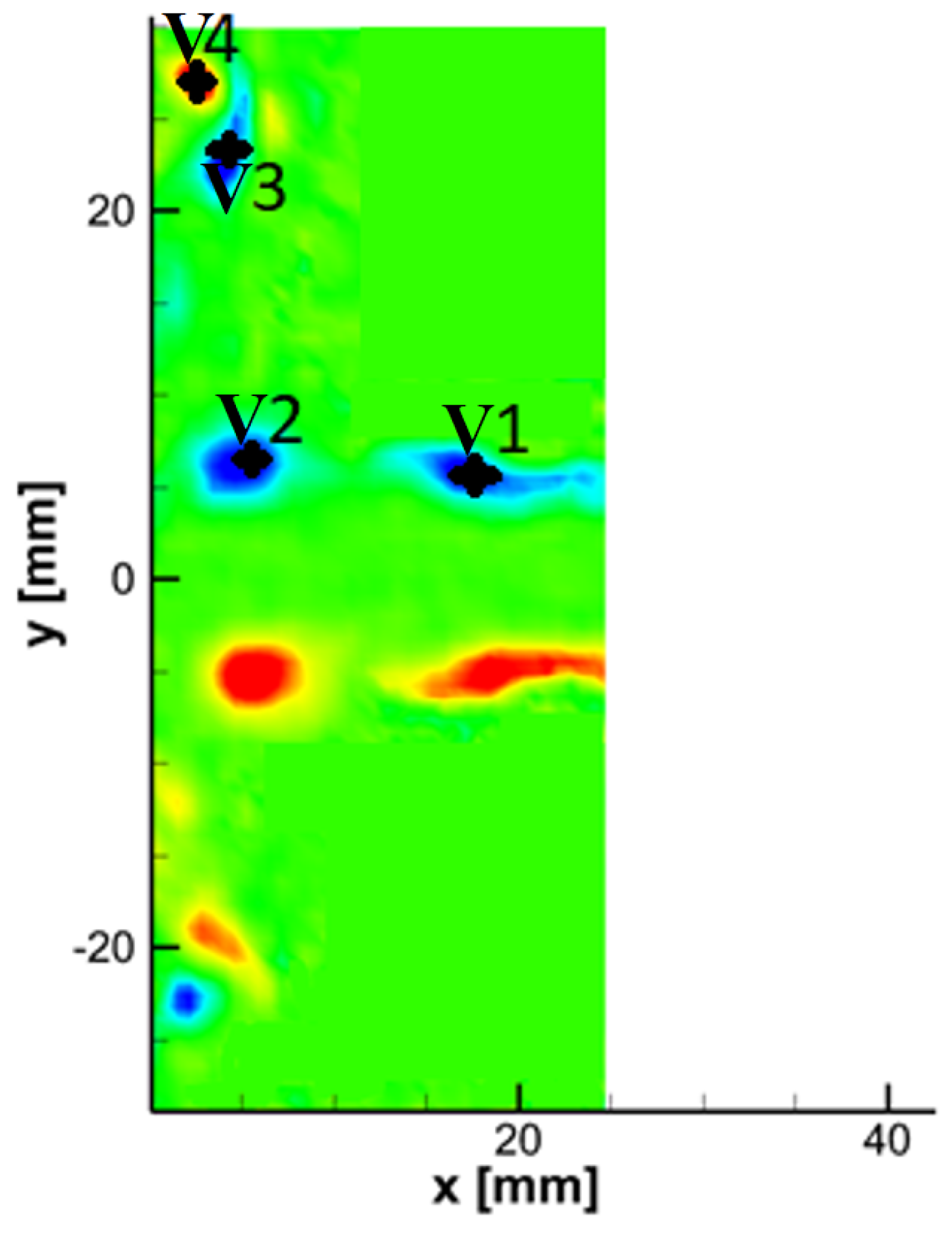
At Re = 3550, the link between acoustic frequencies and vortex behavior was explored by analyzing the transverse velocity spectrum at different points (
Figure 5). The spectra at locations V1, V2, V3, and V4 showed the same main frequencies found in the acoustic measurements, confirming a strong connection between the flow dynamics and the acoustic response.
At point V1, two main frequency peaks appeared at 105 Hz and 202.5 Hz, with 202.5 being stronger in amplitude. At the other points (V2, V3, and V4), the same two frequencies were detected; however, 105 Hz became dominant while 202.5 weakened. These findings suggest that the 105 Hz is linked to a symmetric vortex moving along the first flow path, while 202.5 Hz corresponds to another symmetric vortex following the second path.
At Re = 3750, the transverse velocity spectrum was examined at the same points. Here, a single main frequency at 210 Hz, was observed. Unlike the lower Reynolds case, where two vortex patterns coexisted, this result indicates that at Re = 3750, the flow is governed by a single dominant vortex structure. In this case, vortices from both sides of the jet reach the wall and spread along it following one organized path.
3.2.1. POD Analysis
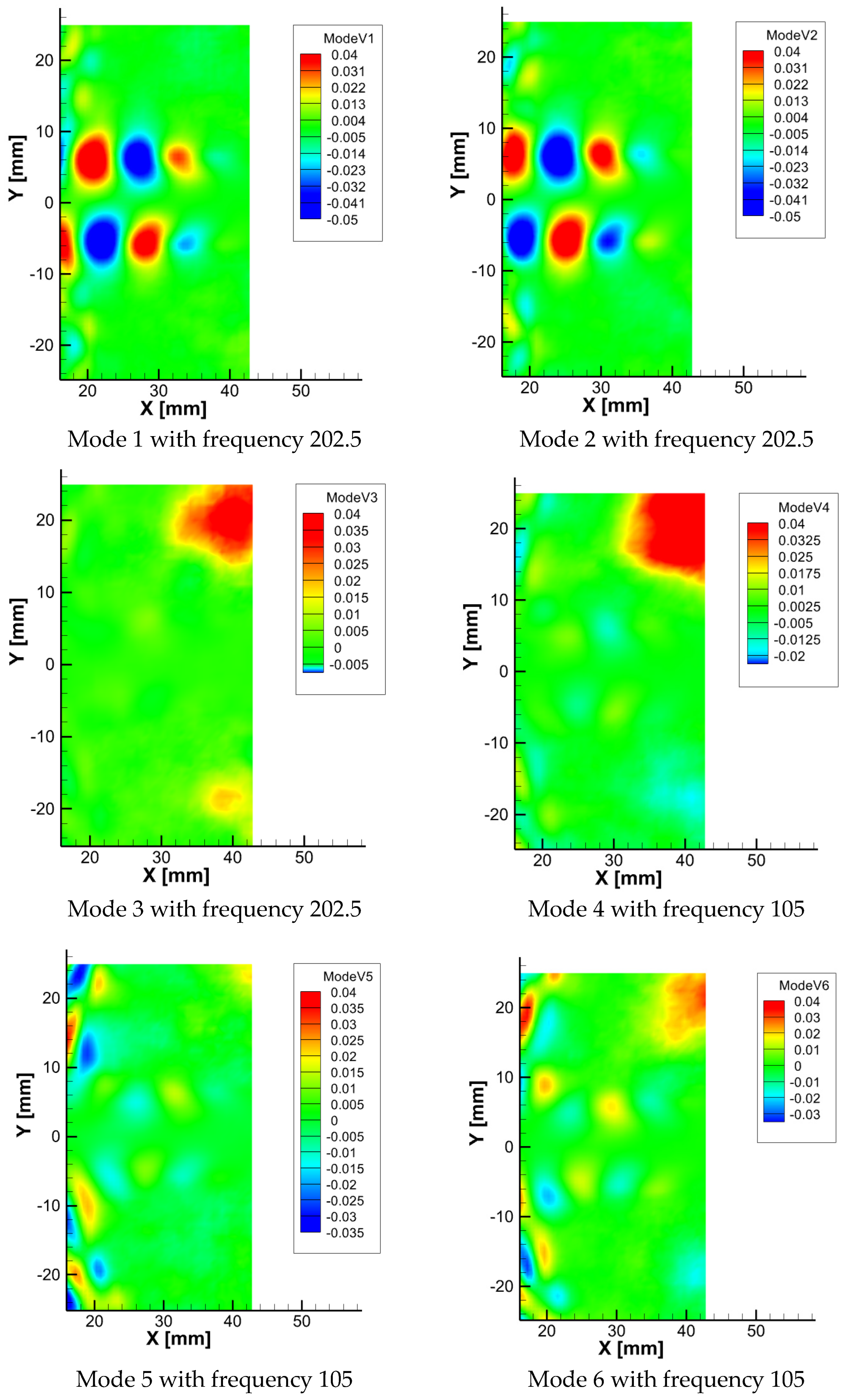
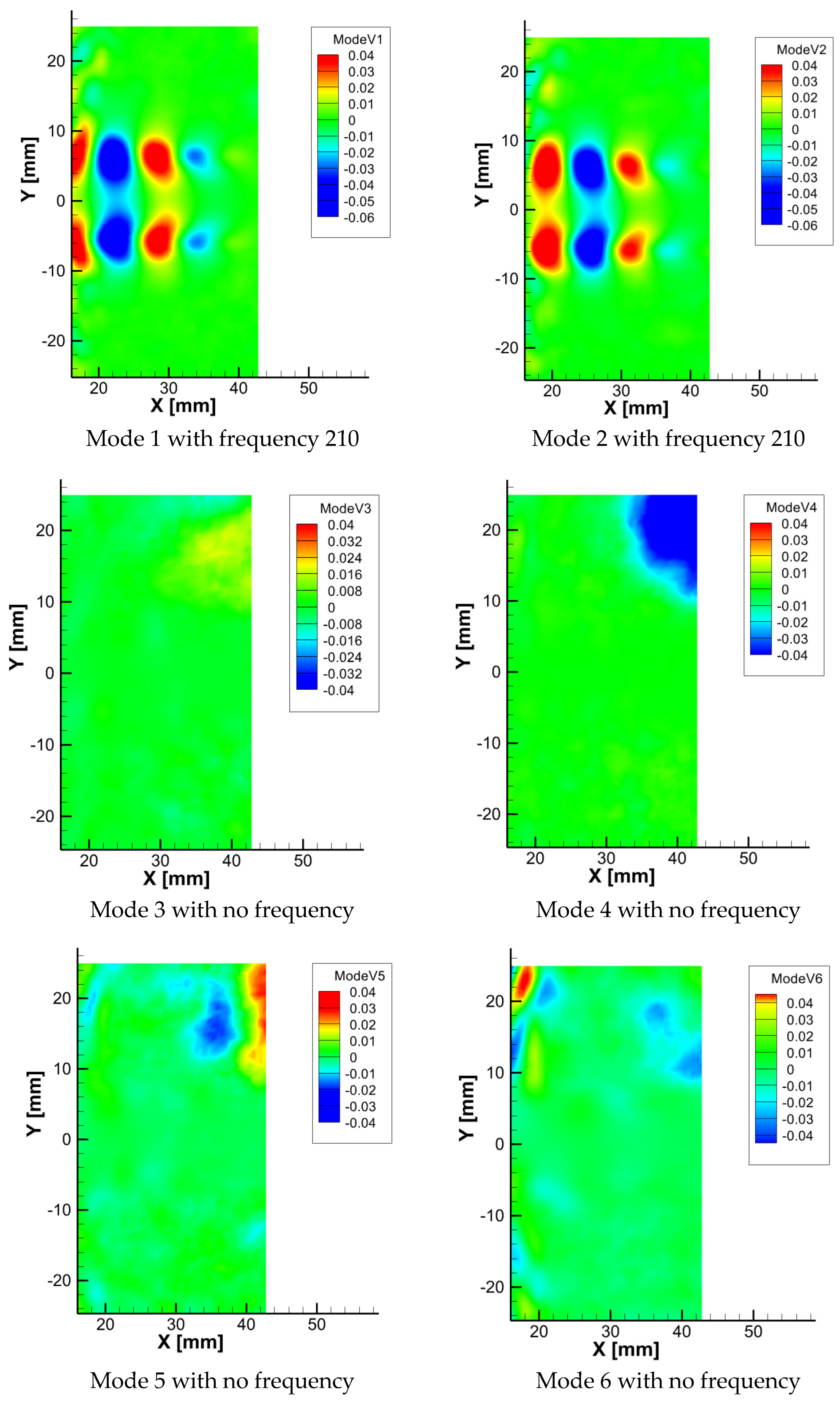
POD analysis was applied to the time-resolved velocity fields to extract the most energetic flow structures and evaluate their role in the dynamics of the impinging jet. The first 8 modes were examined for both Reynolds numbers to identify the dominant frequencies and understand how these structures are spatially organized.
At Re = 3550, the first eight modes (
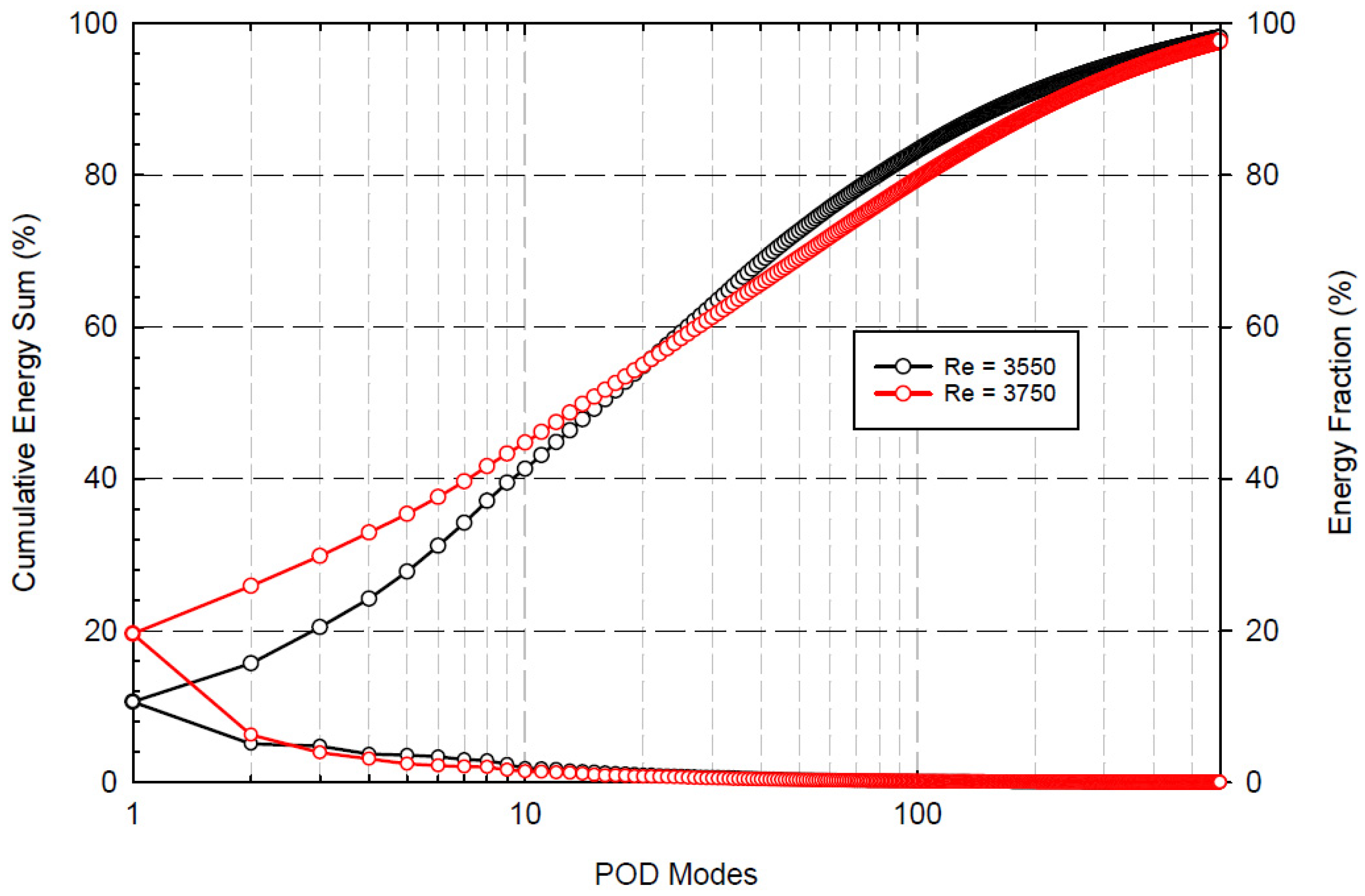
Figure 6) capture the key coherent structures governing the jet flow. The first mode alone accounts for 10.6% of the total kinetic energy and likely represents the main large-scale vortex or the most energetic instability. Modes 1–4 (together contributing 24.15% of the total energy) display large coherent structures forming on both sides of the jet, which strike the slotted plate before partially escaping through it. Modes 5–6 (adding 7% of the energy) reveal smaller vortical structures that deform upon impact with the plate and move sideways along the wall, indicating the presence of secondary vortices. As the mode number increases, the energy associated with each mode decreases, showing that the lower modes capture large-scale oscillations and global motion, while higher modes represent localized turbulence near the surface.
At Re = 3750, the flow behaves differently. The vortices develop in an anti-symmetric pattern from their formation until they strike the plate. The first four modes, which carry 32.89% of the total energy, show that most vortices do not pass through the slot but instead spread along the wall with strong transverse motion. Higher modes (5–6), which represent 4.67% of the energy, correspond to weaker and less organized flow features compared to those at Re = 3550.
POD effectively decomposes the velocity field into spatial modes and temporal coefficients, providing a clear picture of the energy distribution and the dominant oscillation frequencies is identified from the FFT of the temporal coefficients of the leading POD modes.
For Re = 3550 (
Figure 7), the temporal spectra of the POD coefficients show that Modes 1–3 are dominated by the higher frequency at 202.5 Hz, while also showing a weaker component at 105 Hz. In contrast, Modes 4–6 exhibit the opposite behavior, with 105 Hz being dominant and 202.5 Hz appearing with lower intensity. These results align with the dynamic flow observations, suggesting that Modes 1–4 correspond to the two main vortex paths between the nozzle and the plate, while Modes 5–6 represent post-impingement vortices and secondary structures near the wall.
For Re = 3750 (
Figure 8), the spectral behavior changes significantly. Modes 1 and 2 are dominated by a single frequency at 210 Hz, with no strong secondary peaks. Modes 3–6 display low, stable amplitudes without any clear frequency dominance. This indicates that the flow at higher Reynolds number is governed by one main vortex organization, while the secondary vortices that appear near the wall after impingement are much weaker.
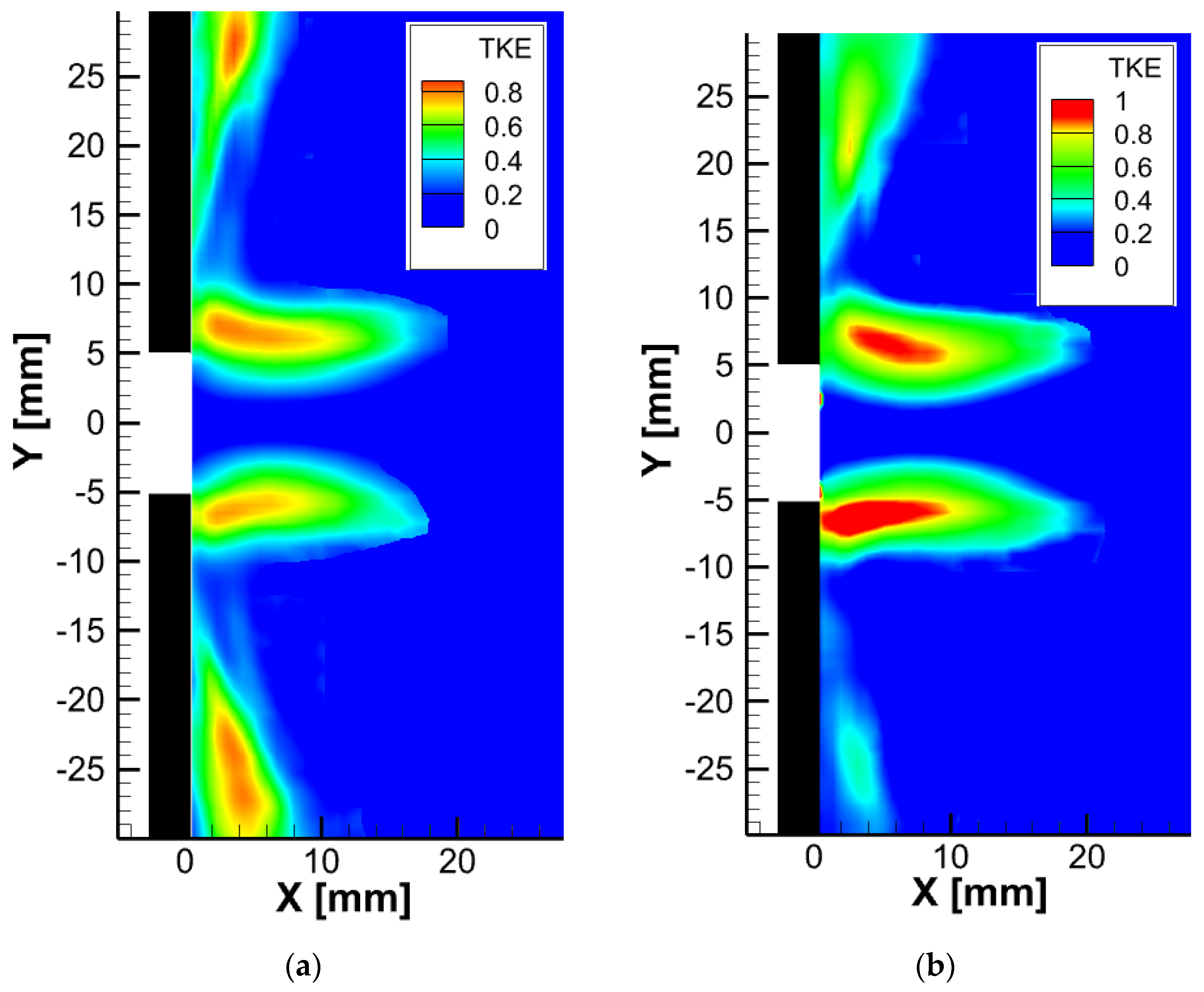
3.2.2. The Turbulent Kinetic Energy (TKE) Distribution
The turbulent kinetic energy (TKE) distribution obtained from the PIV measurements is shown in
Figure 9. The TKE field highlights regions of strong velocity fluctuations associated with the development of the jet shear layers and the interaction between the jet and the impingement plate. For both Reynolds numbers, two main regions of turbulent activity can be observed. The first region, which corresponds to the highest TKE values, is located near the slot in the impingement region. The second region, characterized by lower TKE values, appears close to the wall of the slotted plate. At Re = 3550, which corresponds to higher sound pressure levels, the turbulent kinetic energy near the wall region is higher than that observed at Re = 3750, where the sound pressure level is lower. This evolution suggests a progressive reorganization of the turbulent structures within the impingement region rather than a purely random fluctuation induced by the small Reynolds number increment. Furthermore, the observed TKE redistribution remains consistent with the POD modal organization and the flow–acoustic correlation analysis.
3.3. Heat Transfer Analysis
3.3.1. Mean Temperature Fields
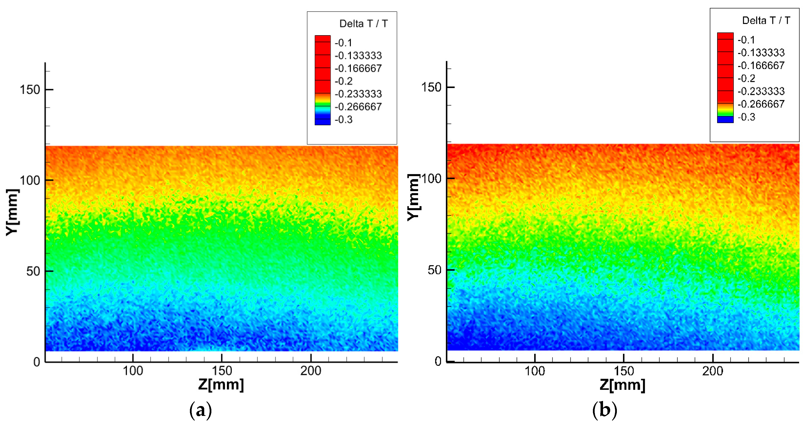
Infrared thermography was employed to measure the surface temperature distribution of the slotted plate under steady-state conditions (
Figure 10). The normalized temperature maps for both Reynolds numbers were obtained by subtracting the steady-state cooled plate temperature from that of the no-jet case and dividing by the average steady-state temperature. For both flow conditions, the most pronounced cooling occurred near the jet impingement region (5 mm < Y < 20 mm), where the primary vortices interact directly with the plate surface. Moving away from this zone, the cooling effect gradually weakened, reaching its minimum near Y = 120 mm. The average steady-state surface temperatures were 43.5 °C for Re = 3550 and 41.5 °C for Re = 3750, corresponding to a 2 °C reduction as a result of the higher jet velocity.
3.3.2. Local and Average Stanton Number Distribution
From the measured temperature fields, both local and average Stanton numbers were derived to assess the convective heat transfer behavior.
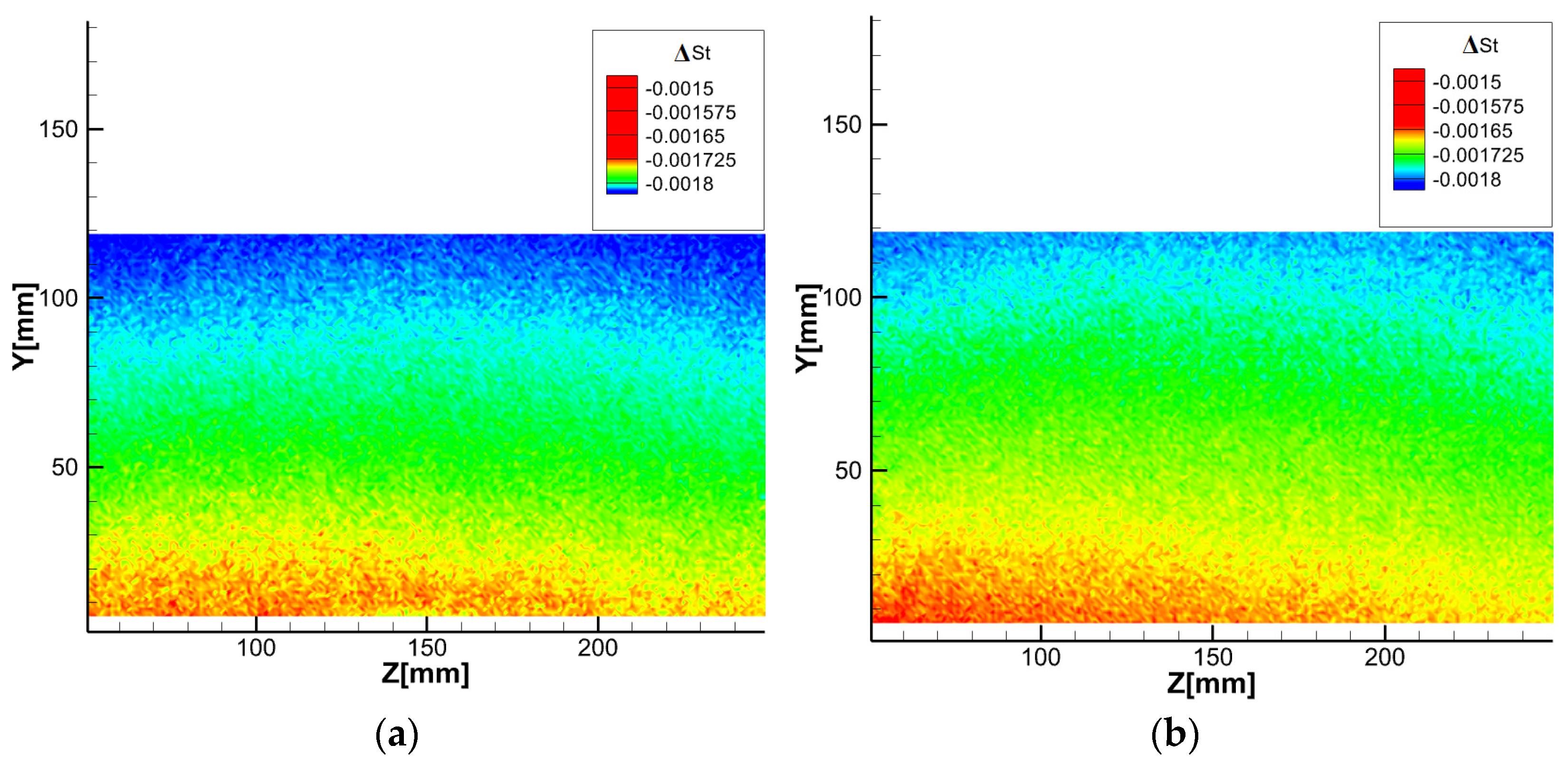
Figure 11 presents the local Stanton number distributions for two Reynolds numbers (Re = 3550 and Re = 3750) at an impact distance of four. It should be noted that the values presented correspond to the variation in the Stanton number (ΔSt) relative to the reference case. The Stanton number variation was calculated using the temperature difference between the modified configuration and the reference condition. Therefore, negative values of ΔSt indicate a local reduction in heat transfer performance relative to the reference case, rather than negative absolute Stanton numbers. The color scale reflects the cooling intensity, where the most negative values correspond to the coldest regions. The highest Stanton numbers occur at the jet stagnation point, indicating the region of maximum heat transfer. As the plate temperature increases and reaches steady-state conditions, the Stanton number gradually decreases.
For both Reynolds numbers, the Stanton number distribution exhibits a distinct wave-like pattern. The highest Stanton values (red) are observed at the jet impingement zone, decrease to intermediate levels (green) near the primary vortices, and reach their lowest values (blue) toward the plate edges (Y = 120 mm). At Re = 3750, the high-Stanton region is broader and more intense than at Re = 3550, confirming improved heat transfer performance at higher jet velocity. Specifically, for Re = 3550, the coldest region (ΔSt = −0.00165) spans Y = 5–16 mm, while for Re = 3750, it extends across Y = 5–26 mm with ΔSt = −0.001575.
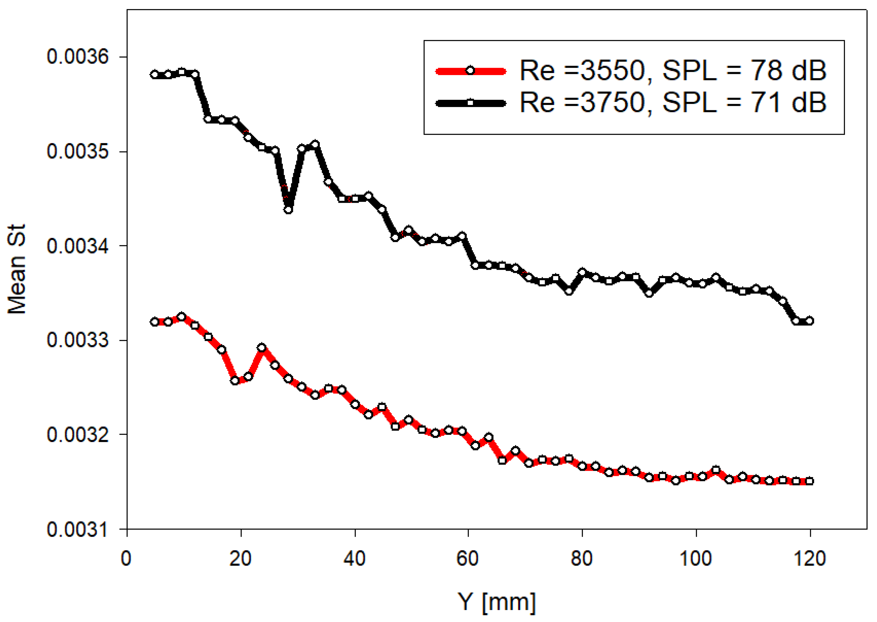
Figure 12 presents the distribution of the average Stanton number variation along the transverse direction for both flow conditions. Two distinct peaks appear in each case. The first peak, located near Y ≈ 6 mm, corresponds to the impingement zone of the primary vortices, while the second peak represents the region of secondary vortex formation, occurring just upstream of the separation point. At Re = 3550, this secondary peak appears at Y ≈ 22 mm, whereas at Re = 3750, it shifts downstream to approximately Y ≈ 30 mm. This displacement indicates a downstream movement of secondary vortex formation, consistent with the vortex dynamics discussed in the following section.
In terms of magnitude, the Stanton number at Re = 3550 reaches about 0.00332 in the impingement region and decreases to approximately 0.00315 near the plate edge. At Re = 3750, these values rise to around 0.00358 and 0.00332, respectively. Overall, the results show that increasing the Reynolds number from 3550 to 3750 enhances the average heat transfer by 6.6%, confirming that stronger jet momentum and vortex organization significantly improve convective performance.
4. Discussion
To isolate the effect of a mild increase in jet velocity on convective heat transfer, two closely spaced Reynolds numbers (Re = 3550 and Re = 3750) were investigated.
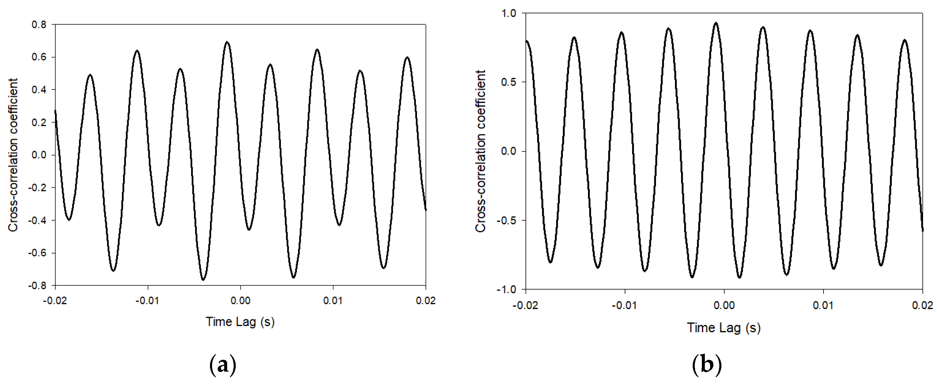
Figure 13 presents the cross-correlation between the first temporal POD coefficient and the acoustic signal for both Reynolds numbers. At Re = 3550, the maximum cross-correlation reaches 0.76, indicating a moderate level of synchronization between the dominant flow structure and the acoustic field. At Re = 3750, the peak correlation increases to 0.93, revealing a much stronger temporal alignment between the dynamic mode and the acoustic fluctuations. This increase in synchronization occurs despite a decrease in overall sound pressure level from 78 dB to 71 dB, confirming that coherence between structures is more relevant than acoustic amplitude alone.
From a vortex dynamics perspective, the results indicate two distinct flow organizations. At Re = 3550, the first POD mode captures 10.6% of the fluctuating kinetic energy, reflecting a distributed energy content among multiple interacting structures. This multi-mode behavior is consistent with the moderate cross-correlation level and suggests that vortex shedding and acoustic feedback are only partially synchronized. Conversely, at Re = 3750, the energy associated with the first POD mode energy nearly doubles to 19.6%, indicating a stronger concentration of energy within a dominant coherent vortex structure. The elevated cross-correlation value (0.93) confirms that this dominant vortex motion becomes tightly synchronized with the acoustic field, suggesting the emergence of a more dynamically organized regime.
Direct quantitative validation with previously published studies remains challenging due to differences in nozzle geometry, confinement conditions, Reynolds number ranges, acoustic behavior, and experimental methodologies reported in the literature. In particular, studies combining synchronized acoustic measurements, POD analysis, PIV characterization, and infrared thermography for rectangular impinging jets operating under self-sustained tonal conditions remain limited. Nevertheless, the observed trends regarding coherent structure organization, modal energy concentration, and heat transfer enhancement remain qualitatively consistent with previously reported impinging jet investigations.
In terms of heat transfer performance, a 6.6% enhancement in the average St. These results demonstrated that organized vortex dynamics and flow–acoustic synchronization govern the observed heat transfer enhancement and noise reduction. Overall, the findings provide new insights into heat transfer enhancement in the presence of acoustic resonance and its influence on resonance-driven thermal performance in impinging jet cooling systems.
The consistency observed between TKE distribution, POD modal behavior, acoustic response, and heat transfer evolution suggests that the reported trends are associated with coherent modifications of the impinging jet dynamics rather than isolated experimental variability.
5. Conclusions
The combined application of PIV, POD, acoustic measurements, and infrared thermography enabled a comprehensive characterization of the coupling between flow dynamics and convective heat transfer in rectangular impinging jets. Although the Reynolds number increased only marginally from 3550 to 3750, corresponding to a modest outlet velocity variation (5.5 to 5.75 m/s), the average Stanton number increased by 6.6% simultaneously with a decrease in acoustic level by 7 dB.
At Re = 3550, the flow dynamics exhibited a multi-frequency behavior characterized by a dominant frequency and its subharmonic frequency at approximately 105 Hz and 202.5 Hz. These frequencies were identified in the acoustic signal and were also detected in the temporal evolution of the dominant POD modes. The 202.5 Hz structures were mainly located in the shear-layer region between the nozzle and the plate, while the 105 Hz structures appeared closer to the impinged plate. This distributed dynamical behavior is consistent with the POD results, where the first mode captured 10.6% of the fluctuating kinetic energy and the cross-correlation with the acoustic signal reached 0.76.
In contrast, at Re = 3750, the acoustic signal revealed a single dominant frequency of approximately 210 Hz, which was also identified in the dominant POD temporal mode. The spatial structures concentrated primarily in the shear-layer region between the nozzle and the impingement plate, corresponding to the Kelvin–Helmholtz instability region. This strong frequency dominance coincided with a significant increase in modal energy concentration, as the first POD mode accounted for 19.6% of the fluctuating kinetic energy. At the same time, the cross-correlation between the dominant POD mode and the acoustic signal increased to 0.93, despite a reduction of approximately 7 dB in the overall sound pressure level.
The results indicate a clear change in the flow behavior between the two Reynolds numbers. When the Reynolds number increases from Re = 3550 to Re = 3750, the acoustic level decreases while the cross-correlation between the acoustic signal and the first POD temporal coefficient increases. This dynamic suggests that part of the fluctuating energy becomes more organized within the dominant POD mode, leading to stronger coherent structures in the jet. The strengthened coherent structures enhance the interaction between the jet and the impingement surface, which results in an increase in the convective heat transfer. These findings highlight that the improvement in thermal performance is mainly associated with the organization of coherent flow structures rather than with an increase in acoustic intensity or bulk velocity alone.
The present study is limited to the investigated rectangular nozzle geometry, nozzle-to-plate spacing, and Reynolds number range associated with self-sustained tonal conditions. Therefore, the reported flow and thermal characteristics may not be directly generalized to different operating conditions or geometrical configurations. In addition, the investigation was conducted using an experimental approach without complementary numerical simulations or active excitation control techniques. Future studies may extend the present analysis to wider Reynolds number ranges and alternative configurations to further generalize the observed flow–acoustic–thermal coupling mechanisms.




 ,
,