Article

Investigation of the Charging and Discharging Cycle of Packed-Bed Storage Tanks for Energy Storage Systems: A Numerical Study

School of Electrical and Mechanical Engineering, University of Portsmouth, Portsmouth PO1 3DJ, UK
*
Author to whom correspondence should be addressed.
Thermo 2025, 5(3), 24; https://doi.org/10.3390/thermo5030024
Submission received: 28 May 2025 / Revised: 9 July 2025 / Accepted: 16 July 2025 / Published: 18 July 2025

Abstract

In recent years, packed-bed systems have emerged as an attractive design for thermal energy storage systems due to their high thermal efficiency and economic feasibility. As integral components of numerous large-scale applications systems, packed-bed thermal energy stores can be successfully paired with renewable energy and waste heat to improve energy efficiency. An analysis of the thermal performances of two packed beds (hot and cold) during six-hour charging and discharging cycles has been conducted in this paper using COMSOL Multiphysics software, utilizing the optimal design parameters that have been determined in previous studies, including porosity (0.2), particle diameters (4 mm) for porous media, air as a heat transfer fluid, magnesia as a storage medium, mass flow rate (13.7 kg/s), and aspect ratio (1). The performance has been evaluated during both the charging and discharging cycles, in terms of the system’s capacity factor, the energy stored, and the thermal power, in order to understand the system’s performance and draw operational recommendations. Based on the results, operating the hot/cold storage in the range of 20–80% of the full charge was found to be a suitable range for the packed-bed system, ensuring that the charging/discharging power remains within 80% of the maximum.

1. Introduction

The large-scale deployment of renewable energy has been driven by efforts to reduce greenhouse gas emissions and increase energy security. The International Energy Agency (IEA) reports that, in 2020, 29% of the electricity generated globally was generated by renewable sources [1,2]. It has been predicted that this percentage will increase to 49% by 2030 [3,4]. Accordingly, thermal energy storage systems (TESs) will play an important part in overcoming the intermittency inherent in many renewable energy technologies, such as solar and wind energy [4].
TESs become increasingly important for the modern grid to incorporate as energy storage technologies, such as pumped thermal energy storage (PTES), to help integrate a greater number of variable renewable energy sources. In the area of large-scale energy storage, the PTES is a highly promising and developing technology. In comparison to other thermal energy storage systems like compressed-air energy storage (CAES), it provides substantial, well-established capacity but is restricted by the necessity for specific underground caverns and often depends on fossil fuels, leading to decreased efficiency. While liquid-air energy storage (LAES) can be implemented in various locations, it has moderate efficiency levels (around 50–60%). In contrast to CAES and LAES, PTES has a high round-trip efficiency (RTE), a high capacity, a long life span of up to 30 years, and a short response time [5,6,7]. In addition to being environmentally friendly and having a smaller carbon footprint, short start-up times are another benefit of the PTES system [2,4,8], addressing the key deficiencies noted in current technologies. Therefore, PTES is increasingly considered as a next-generation, large-scale, clean energy storage alternative that balances flexibility, efficiency, and environmental impact. Furthermore, the PTES can attain satisfactory round-trip efficiencies of as much as 70% and offer competitive energy and power densities at cost-effective prices, as demonstrated in Table 1.
Various thermal energy storage applications have suggested using packed-bed storage systems (PBSS), including PTES [1,2,3,4,5], advanced adiabatic compressed-air energy storage (AA-CAES) [6,7], and LAES [4], for large-scale application systems.
Packed beds have been recommended for use in other systems involving thermal processes, such as industrial waste heat recovery, renewable solar–thermal frames, and geothermal energy [5]. Packed beds have the potential to be more cost-effective and compact than traditional storage systems, like two-tank liquid stores. Depending on the storage media and the heat transfer fluid (HTF), packed beds also tend to utilize more abundant and locally sourced, environmentally friendly, and non-reactive materials compared to other storage technologies [9].
The packed-bed storage concept has the potential to address the current limitations in heat storage systems related to temperature ranges and storage capacities. However, large-scale units based on this concept are not yet operational, indicating that the full implementation of the technology is still underway [5,9]. This is mainly due to the incomplete extraction of its full potential, which is closely tied to successful system optimization in terms of material selection, design, and thermal management. Achieving high thermal efficiency values comparable to novel storage technologies, along with improved techno-economic performance, relies on addressing these critical points.
As shown in Figure 1, a PBSS consists of three main components, including a storage vessel and storage media. The storage vessel is filled with solid packing material known as the “filler”. The solid particles receive energy through the HTF, which might also serve as the working fluid in the system that includes the packed bed. Numerous different packed-bed designs can be found in various publications [8,10,11,12], featuring differences in the shape, the material used for storage, and the HTF used.
Typically, the storage units are cylindrical, with the HTF flowing along the axis. These packed beds are categorized as sensible heat storage (SHS), as the energy is stored due to the temperature change of the filler material. The use of phase change materials (PCMs) or latent heat storage systems (LHS) could present an alternative approach [13]. However, this may result in increased costs and system complexity. HTFs can be gases, such as air [14,15], carbon dioxide, or argon [16], or can be liquids, such as thermal oils [17] or molten salts [18]. Table 2 presents a general comparison of various PBSS systems using different filling materials, highlighting the advantages and limitations.
The packed-bed thermal tanks are a crucial part of the PTES system, which is an emerging technology for industrial applications [19,20,21]. Since this technology is not yet available commercially and requires further research [21,22,23], optimizing the (hot/cold) packed-bed design is important for improving the PTES system in general and would be a valuable addition to the literature review.
The PTES system has five main components: two storage tanks, a heat pump, a heat engine, and a motor or a generator, where the PTES stores the electrical energy in the form of thermal energy [2]. The conventional PTES layout is shown in Figure 2.
During the charging process, an electrically powered heat pump transfers heat from a low-temperature reservoir (cold tank) to a high-temperature reservoir (hot tank). During the discharging process, the thermal reservoirs are employed to drive a heat engine, which then converts the thermal energy back into electrical energy. Although large systems are usually unaffected by leakage losses, the storage tanks are designed with insulation to reduce the heat loss during storage [24].
Numerous investigations have concentrated on thermal energy storage (TES) systems that utilize packed-bed arrangements, examining them through both experimental and simulation methods. The performance and functioning of these systems are significantly affected by aspects such as the shape, dimension, and void fraction of the packing materials [25,26].
Research has established that computational and mathematical models serve as effective means for optimizing the performance and design of packed-bed storage systems [26,27]. For example, a mathematical model was created to replicate dynamic thermal responses in solar energy applications [27], while another study investigated how variations in void fraction greatly influence transient temperature distributions in both the solid and fluid phases [28]. Studies have also shown that smaller packing elements help reduce axial thermal dispersion and enhance exergy efficiency, indicating that the use of the smallest feasible spheres maximizes storage capacity [18].
Empirical research has generated correlations for heat transfer (Nusselt number) and flow resistance (friction factor) based on the Reynolds number, void fraction, and sphericity. These results indicate that spherical packing elements with the least void fraction provide the most effective thermal and hydraulic performance [29].
Simplified thermal models have been employed to study the temperature behavior in packed beds, such as those utilizing alumina and air as heat transfer materials [30]. Comparisons between radial and axial flow setups have shown that radial-flow designs possess sharper temperature fronts and increased heat losses, yet this results in lower pressure drops [31].
Liquid-air energy storage systems incorporating packed beds have demonstrated promising round-trip efficiencies (50–62%), underscoring their potential for large-scale grid applications (over 100 MW) [32].
In the realm of high-temperature TES, particularly in concentrated solar power (CSP) plants, research underscores the advantages of using rock-based packed beds to effectively drive power cycles [33]. Investigations reveal that smaller particle sizes contribute to improved overall system efficiency [33]. Conical geometries have been designed and verified experimentally to enhance heat transfer while decreasing costs, and these designs have been successfully scaled for use in industrial CSP applications [15,34,35,36,37]. Importantly, truncated conical shapes show greater exergy efficiency compared to cylindrical ones [37].
Pilot-scale systems utilizing ceramic spheres in cylindrical tanks with air have exhibited strong operational performance [38], and packed-bed TES systems have proven effective under cyclic charge–discharge scenarios and when integrated with adiabatic compressed air storage [39]. Ultimately, a large-scale demonstration of high-temperature TES using an integrated organic Rankine cycle has validated the practical feasibility and operational success [40].
This study in this paper has been conducted based on a previous paper’s [9] optimization results. The aim of this paper is to evaluate the performance of this optimally packed bed. This paper concentrates on studying and analyzing the thermal performance of the full cycle of the hot- and cold-packed beds storage in a PTES system by looking at the reservoir’s performance based on the capacity, the energy stored, and the total thermal power. The characteristics of the charging and discharge processes of two solid packed-bed thermal energy storage systems are investigated using COMSOL Multiphysics 5.6 software. The results of this paper offer a recommendation for the optimal operating scenario for this type of packed-bed storage. This guidance aims to address the existing gap in the literature, as this novel system is not yet widely commercialized and requires further research due to the limited studies conducted in this field.

2. Materials and Methods

In this section, the methods and the materials that are used in the simulations are considered.

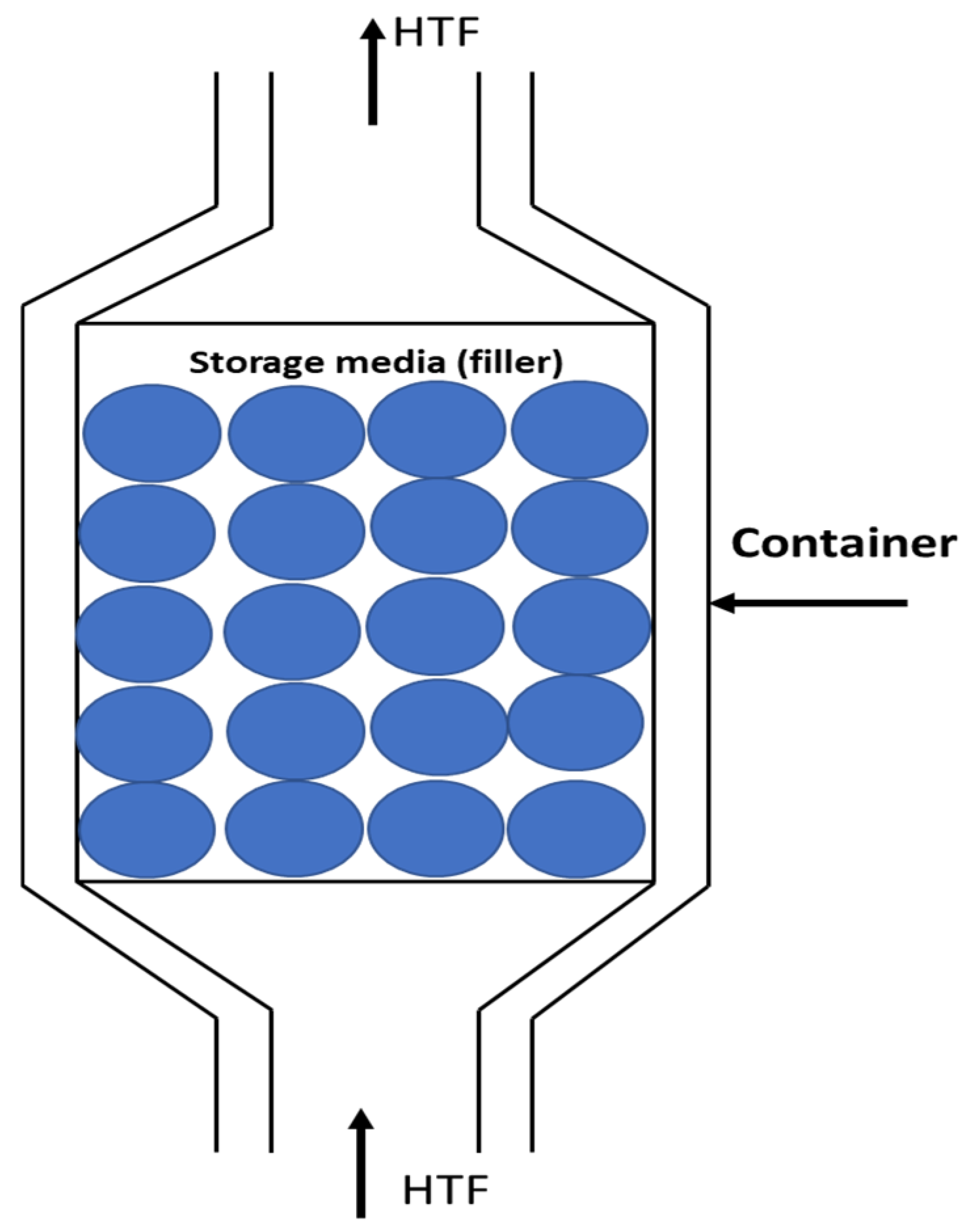
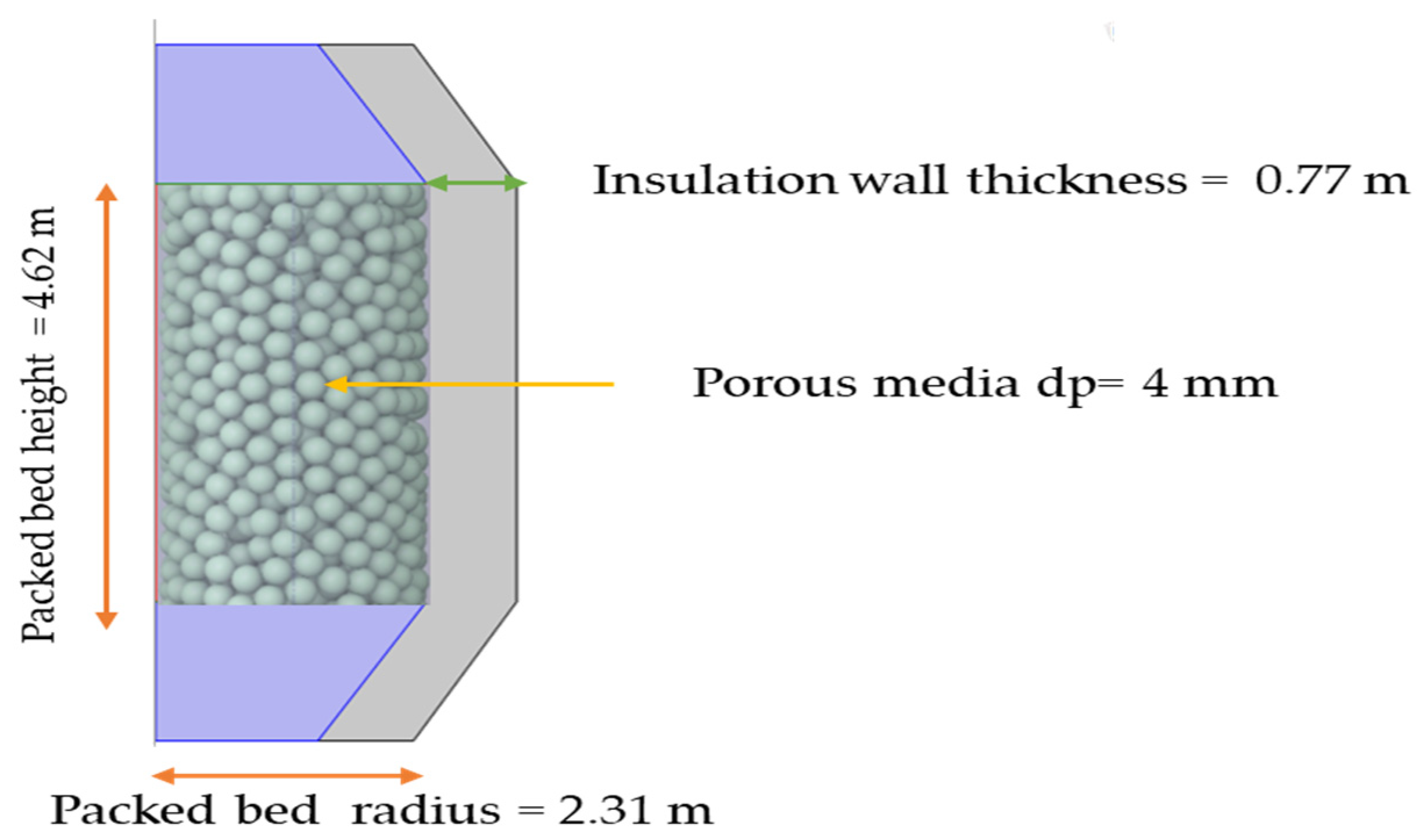
2.1. Model Set-Up and Methodology

A 2D axisymmetric cylindrical model has been built for a fully insulated tank with a vertical configuration, as shown in Figure 3, for the hot reservoir. The cold reservoir has the same configuration, but with a height of 5.45 m and a radius of 2.725. The model was built by applying a porous media formulation provided by the COMSOL 5.6 software. A triangular mesh size is used to mesh the model’s geometry.
The COMSOL default meshes were tested in a mesh-independent study to determine the accuracy of each mesh type. The number of mesh elements varied from 375 for an extremely coarse mesh to 24,688 for an extra-fine mesh. The mesh type, number of elements, and simulation times are presented in Table 3.
The normal, fine, finer, and the extra-fine meshes all provide a good degree of accuracy with only small differences between the results, making them all appropriate for the research. The extra fine mesh was selected since it is the finest mesh, and the simulation time was not excessive. This is demonstrated in Figure 4 for three different heights, namely h = 0.5 m, h = 1.5 m, and h = 3.5 m, illustrating the temperature difference between each mesh and the very-fine mesh.
The applied boundary conditions have been selected as a zero-velocity no-slip wall ( u = 0 ) at the solid boundaries. At the inlet, the boundary condition features a fully developed flow and a constant mass flow rate ( m ˙ = 13.7   k g / s ) , while at the outlet, a pressure condition has been set up to prevent backflow. Adiabatic boundary conditions ( Q = 0 ) are applied at the outer boundary of the insulation material. The fluid chosen for the simulation is incompressible flow, with operating pressures of 10.5 bar and 1.05 bar for the hot and cold storage reservoirs, respectively.
Following [9], this paper considers two cylindrical (hot and cold) packed-bed reservoirs filled with particles of magnesia and using air as the HTF. Table 4 presents the dimensions of both storage tanks. The packed bed was modeled using the optimal parameters found in [9] and shown in Table 5. The operating pressures of hot and cold storage tanks were 10.5 bar and 1.05 bar, respectively.
Following [9], the numerical approach used here was also applied in [9], where it was validated against the experimental work of Meier et al. [42]. Following this, it was applied to a large-scale system, based on the dimensions of White et al. [41] to determine the optimal parameters that are applied to both tanks in this work and shown in Table 5.

2.2. Numerical Model

The simulations were performed in COMSOL 5.6 using a modification of the one-dimensional Schumann equations [43]. COMSOL Multiphysics is an advanced, commonly used software tool intended for modeling different physical phenomena, including the flow of fluids through porous materials and thermal transfer processes. Its primary benefit is the capacity to combine several physics models, enabling the simulation of intricate multiphysics systems. The porous medium is a composite material composed of both voids and solid particles. A wide variety of industrial sectors employ heat and fluid movement in porous media, including high-temperature packed-bed applications, chemical reactors, and gas separation adsorbent beds. Considering the particular needs and preferences for this simulation project, COMSOL has been chosen as the most suitable option.
Given that a porous medium is made up of a solid structure filled with a fluid, heat is transferred at different rates through these two types of media. If the heat exchange between the fluid and the solid structure occurs almost instantaneously—relative to the time scale being considered—it can be assumed that their temperatures are equal. As a result, a state of thermal equilibrium is achieved, causing the temperature equation for porous media to correspond with the convection–diffusion equation, utilizing thermodynamic property averaging models to represent both the solid structure and fluid properties. The Heat Transfer in Porous Media Interface provides tools and guidance for establishing an appropriate matrix model [44].
If the assumptions mentioned earlier cannot be applied, indicating that the fluid and matrix are not in thermal equilibrium, a two-temperature model becomes necessary to model heat transfer. The heat transfer in the solid matrix is represented by The Heat Transfer in Solids Interface, while the fluid’s heat transfer is characterized by The Heat Transfer in Fluids Interface. The interaction of heat between the two is described by the Local Thermal Non-Equilibrium Multiphysics coupling [44].
In this paper, the studied mode solution relied on the local thermal non-equilibrium equation, Fourier’s law, and non-Darcian flow principles. To describe heat transfer in a porous medium, the local thermal non-equilibrium hypothesis employs the temperature field.
A modified version of the widely used one-dimensional Schumann equations [43] is used to simulate the porous media, and the continuity and momentum equations are given by.
( ρ u ) ε t + . ρ u u ε 2 = . μ u p + ρ g μ k + C F ρ k u u
( ε ρ ) t + . ρ u = 0  
where ρ is the porous media density, μ is the viscosity, C F is the Forcheimer parameter, and u = ε v is the superficial and v is the interstitial velocity.
Furthermore, the Shuman approach addresses two coupled differential equations separately; one pertains to solids and the other to the heat transfer fluid (HTF).
The two coupled energy equations are solved for the solid, and the HTFs [44] are shown in Equations (3) and (4) respectively:
θ s ρ s c p . s T s t + . q s = q s f T f T s + θ s Q s
ε ρ f c p . f T f t + ρ f c p . f u p . T f + . q f = q s f T s T f + ε Q f
where cp is the heat capacity, q is the conductive heat flux, Q is the heat source, and T is the temperature, and the subscripts s and f refer to the solid and fluid phases, respectively. Additionally, θs is the solid volume fraction, and qsf is the coefficient of the interstitial convective heat transfer.
COMSOL uses Equations (5)–(7) to numerically solve for the heat transfer in solid storage materials [44]:
ρ f c p u . T s + . q = Q s + Q t e d
Q t e d = α T : S t
q s = K T
where Qs is the solid heat source; Q t e d is the thermoelastic damping contribution straight from the solid mechanics interfaces; q is the conductive heat flux; is the gradient operator; S is the second Piola–Kirchhoff tensor; and ∂S/∂t is the operator is the material derivative.
While Equations (8)–(10) are utilized to numerically solve for the heat transfer in the heat transfer fluid [44]:
ρ f c p u . T f + . q f = Q f + Q p + Q v d
Q v d = τ . u
q f = K T f
where Q v d is the viscous dissipation in the fluid, and τ is the viscous stress tensor.
In the context of the local thermal nonequilibrium hypothesis, the modified version of Fourier’s law of conduction is presented in Equations (11) and (12) [44]:
    q s = θ s k T s
q f = ε k T f
where k is the solid thermal conductivity.
For this study, we have R e > 300 corresponding to non-Darcy flow and fully developed turbulence. The corresponding relationship between the pressure gradient and velocity is given by [42]:
p = μ k u + C F k ρ u u
where CF is the Forcheimer parameter, p is the pressure, and k is the permeability. The Reynolds number for flow through a porous medium is given by [44]:
R e = d p ρ u 1 ε μ
For the studied model, the flow regime is fully turbulent, with a Reynolds number greater than 300.
This study uses the standard Reynolds-averaged Navier–Stokes (RANS) standard k-ε model to solve the fluid flow in the porous media using Equations (15) and (16) [44]:
ρ u . k = . μ + μ T σ k k + P k ρ ε
ρ u . ε = . μ + μ T σ ε ε + C ε 1 ε k P k C ε 2 ρ ε 2 k
where μ T = ρ C μ k 2 ε , C μ = 0.09 is the k- ε based model constant, P k = μ T u : u + u T 2 3 . u 2 2 3 ρ k . u , μ is the dynamic viscosity of the fluid, μ T is the eddy viscosity, and C ε 1 = 1.44 ,   C ε 2 = 1.92 ,   σ ε = 1.30 ,   C σ κ = 1.00 are constants [45].
The use of RANS limits the simulation to considering time-averaged quantities, rather than the instantaneous velocities. The k-ε model is then required to model the Reynolds stress terms, which derive from the missing fluctuating velocities.

2.3. Materials Properties

Magnesia is selected as the optimal storage medium for the packed bed based on [9]. Magnesia, also known as “Magnesite brick”, belongs to the category of basic refractory bricks. It is an alkaline refractory material with over 90% magnesium oxide content and a primary crystal structure known as periclase.
Magnesia is highly resistant to heat, alkali slag, and softening under load, but it is not resistant to thermal shock. Sintered magnesia brick is produced by crushing, batching, mixing, and molding the raw materials and then firing them at a high temperature of 1550–1600 °C. For high-purity products, the firing temperature exceeds 1750 °C. After mixing, molding, and drying, the bricks are left in an unburnt state [46]. Table 6 provides a summary of the thermophysical and chemical properties of Magnesia.

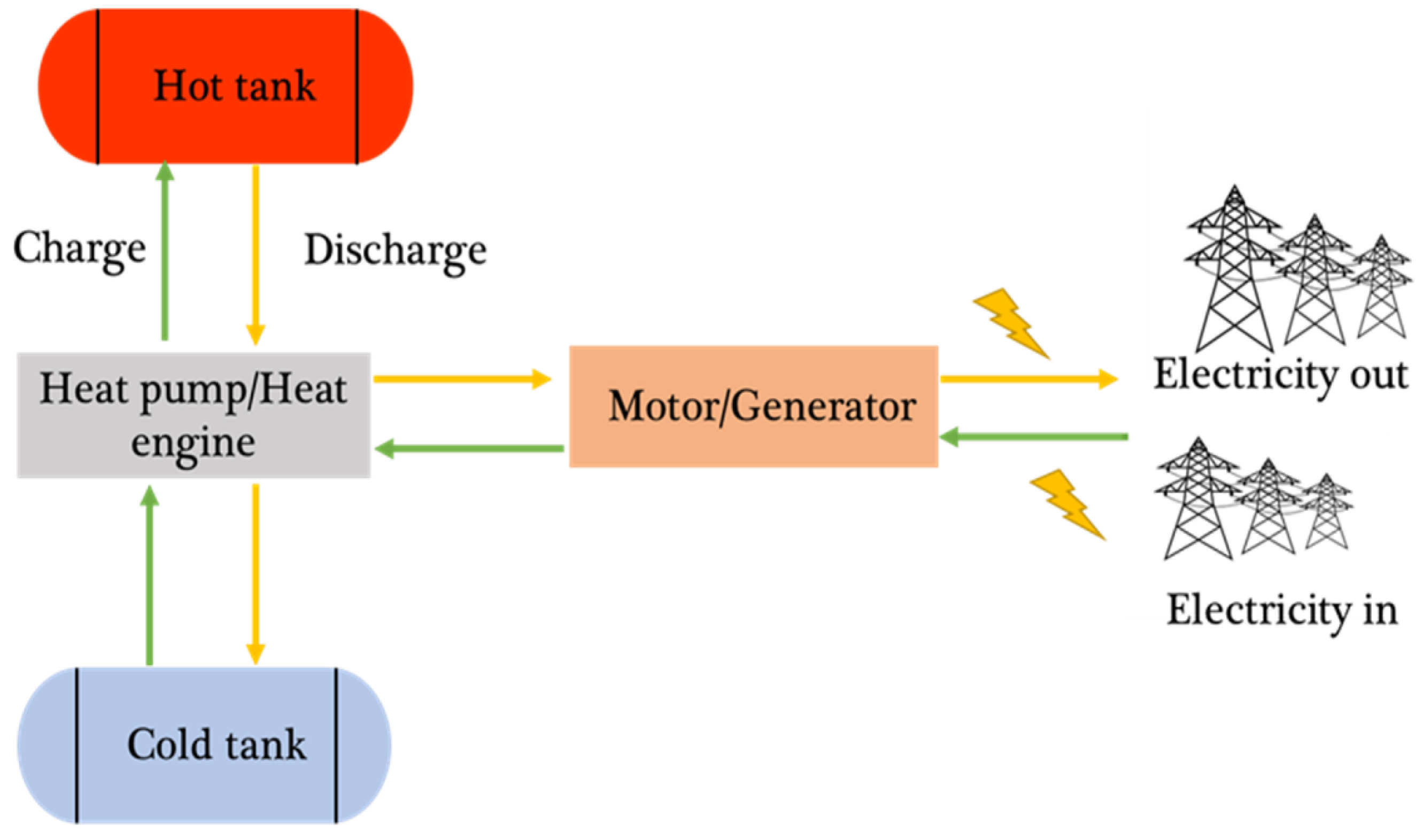
2.4. Modeling Hot/Cold Thermal Energy Storage

The hot/cold storage charging process involved using the HTF based on the charging temperatures provided in Table 4, with 476 °C for hot storage and −154 °C for cold storage. During this process, the HTF (air) was circulated continuously through the SHS storage tank. The HTF exchanged its energy with magnesia particles with 4 mm particle diameters and a 0.2 void fraction, and the tanks have an aspect ratio of 1.
At the beginning of the charging process, the temperature of the magnesia inside the packed bed was ambient temperature (25 °C). As the charging process progressed, energy storage was achieved by heat transfer with the solid-packed material. The charging process continued until the solid-packed material reached 98% of its full charge for both the hot and the cold reservoir. The discharge process was then modeled, starting from the final charging position. The direction of the air flow was reversed, with the air entering at 476 °C for the hot storage and −154 °C for the cold.
The thermal performance of the packed bed during the charging and discharge process was evaluated using three criteria: the capacity factor (CF), the total energy stored, and the thermal power. A recommendation for the packing bed operation strategy is then drawn based on the results of these studies.
The capacity factor and the total energy storage calculation methods are shown in Equations (1) and (2) [41]:
The CF is the energy as a fraction of the total capacity during the charging/discharging [47]:
  C F = 0 L 1 ε π 4 D 2 ρ s c p s T s ( z ) T s , i d z 1 ε π 4 D 2 ρ s c p s L T f i T s , i
Here, the CF represents the fraction of the total storage capacity that is filled. The governing equation includes several parameters, as well as solid particle and HTF properties. ε is the material porosity. D is the packed bed diameter. ρ s is the material density. Cp is the material-specific heat capacity. Ts is the solid material temperature, while the TF is the heat transfer fluid temperature. The total energy stored is found from the numerator of Equation (17):
E stored = 0 L 1 ε π 4 D 2 ρ s c p s T s ( z ) T s , i d z
The thermal power [31] is found from Equation (11):
P T H = E s t o r e d / t
where PTH is the total thermal power, E s t o r e d is the change in the energy stored, and t is the time over which the energy change occurs.

3. Results and Discussion

The following sections involve an analysis of the heat transfer performance of the hot and cold storage reservoirs during both the charging and discharging cycles. The hot and cold storage reservoirs were assessed using the optimal operational parameters listed in Table 2, with air as HTF and magnesia as the storage material.

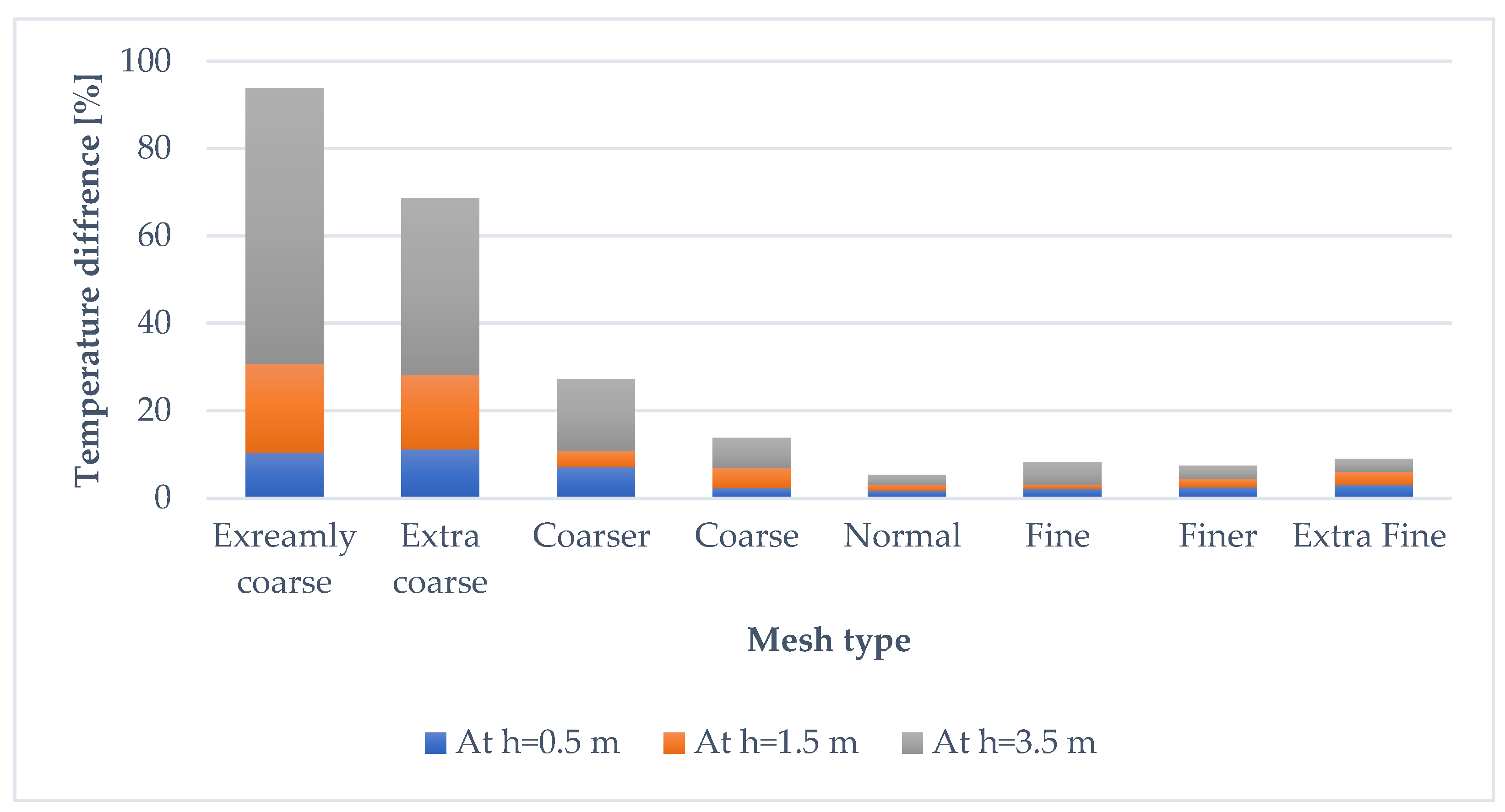
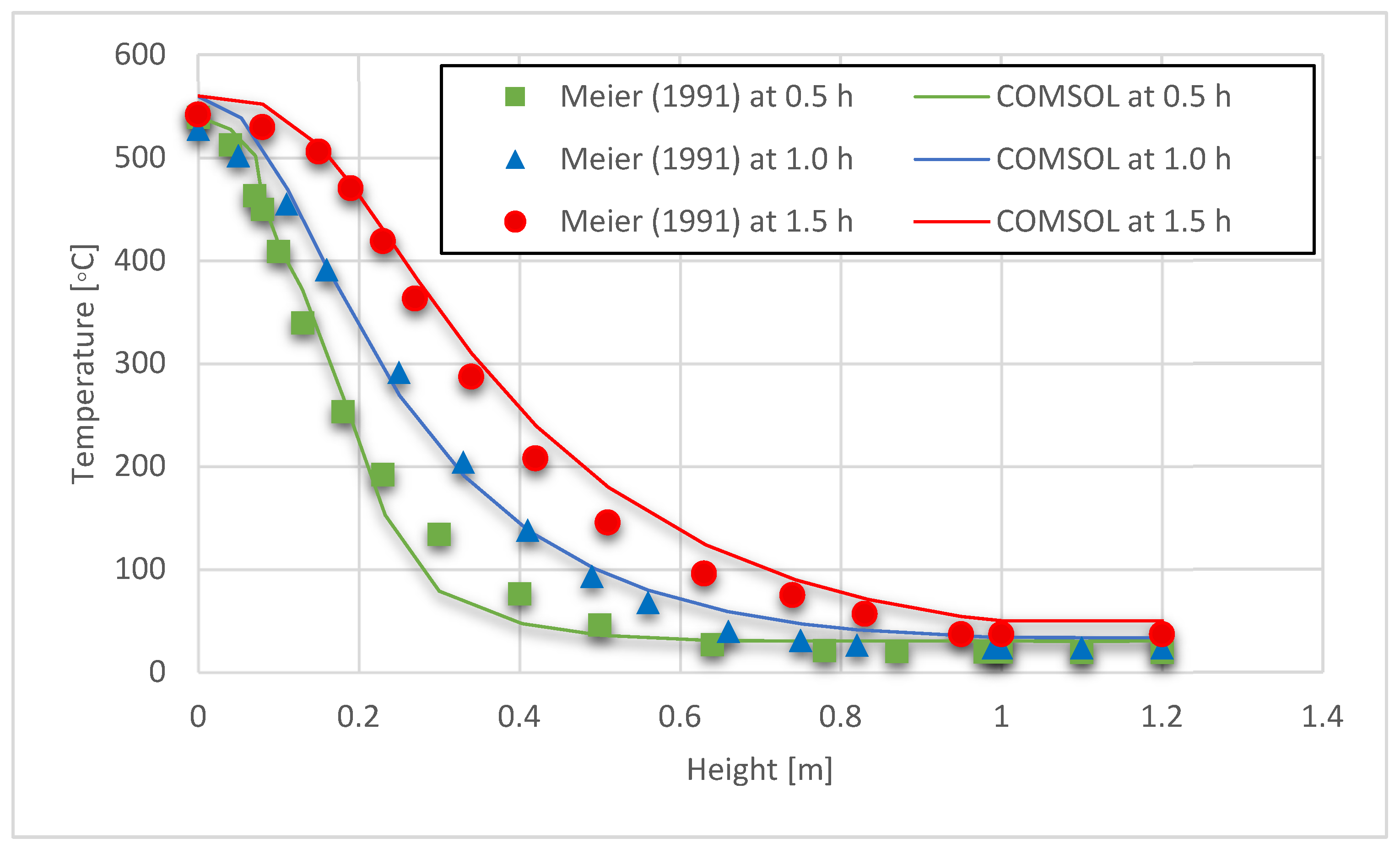
3.1. Model Validation

The model has been validated [9] against the experimental work of Meier et al. [42] for a small-scale tank, as shown in Table 7.
Other than the different parameters and material, as shown in Table 7, the simulation approach applied for the validation was the same as described in Section 2. The results of this validation are shown in Figure 5, which shows good agreement between the two results, although we note that the COMSOL results slightly underestimate the temperatures at the earliest time (0.5 h). Despite this, the agreement is generally good and validates the numerical approach applied here.

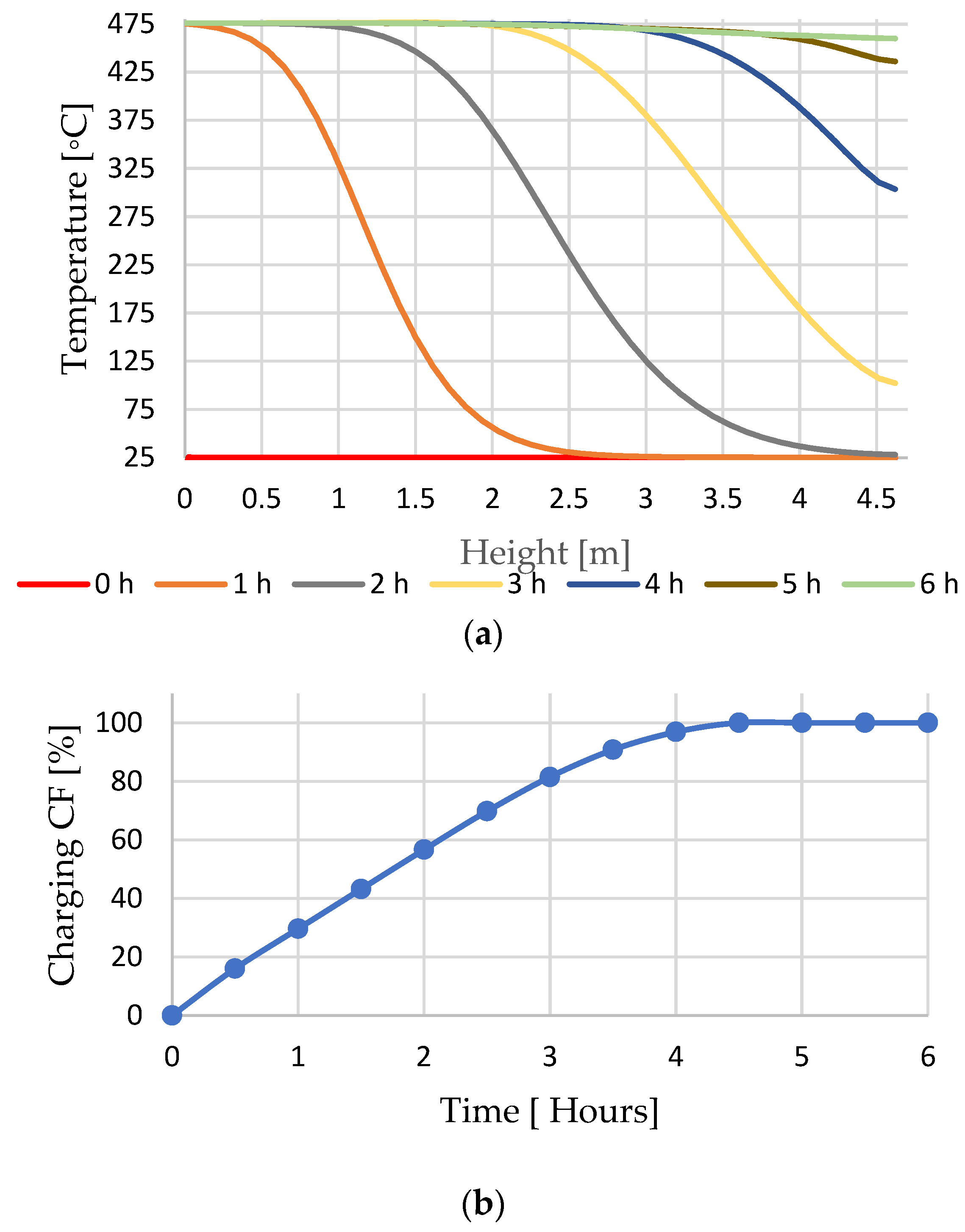
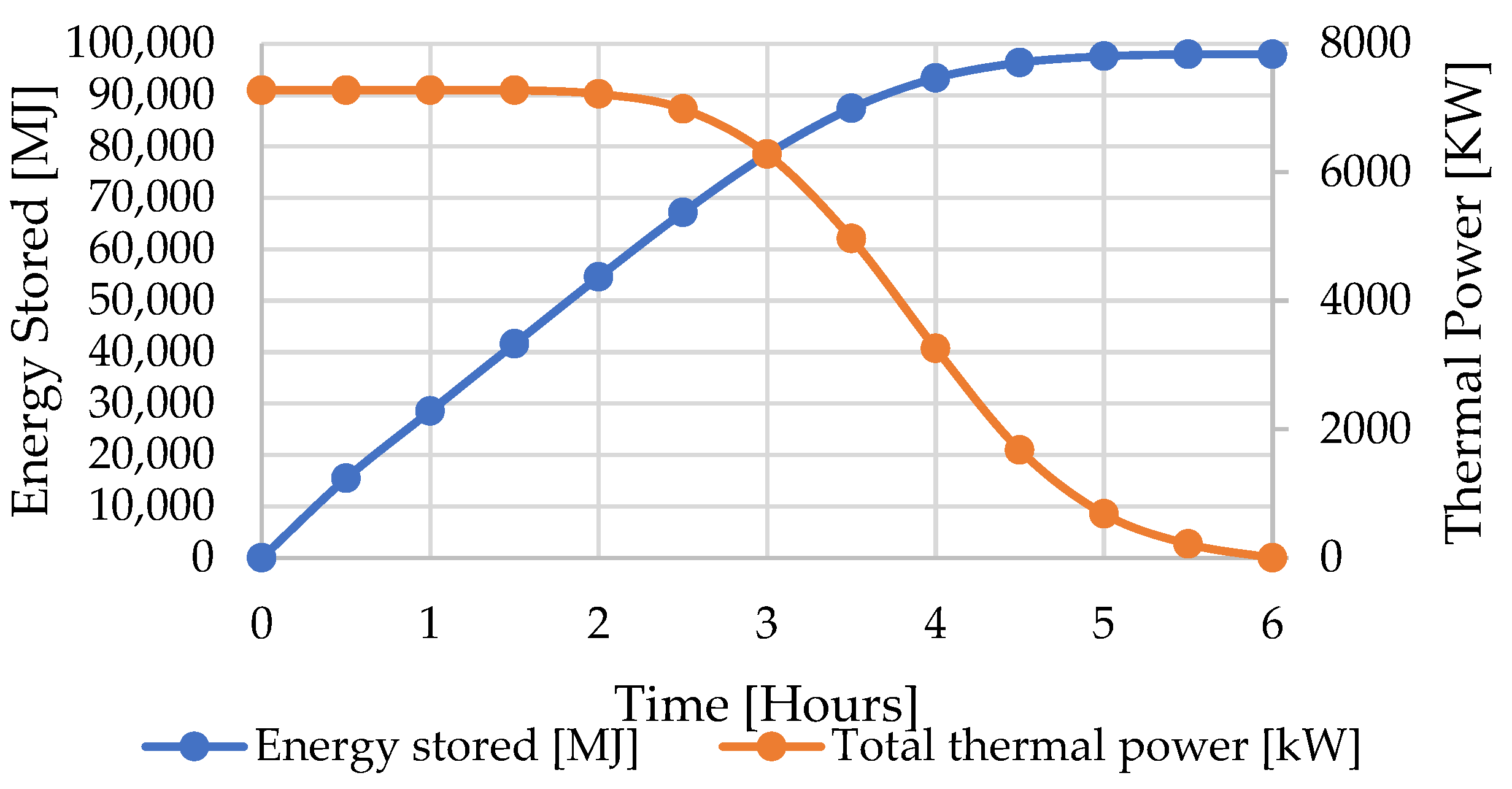
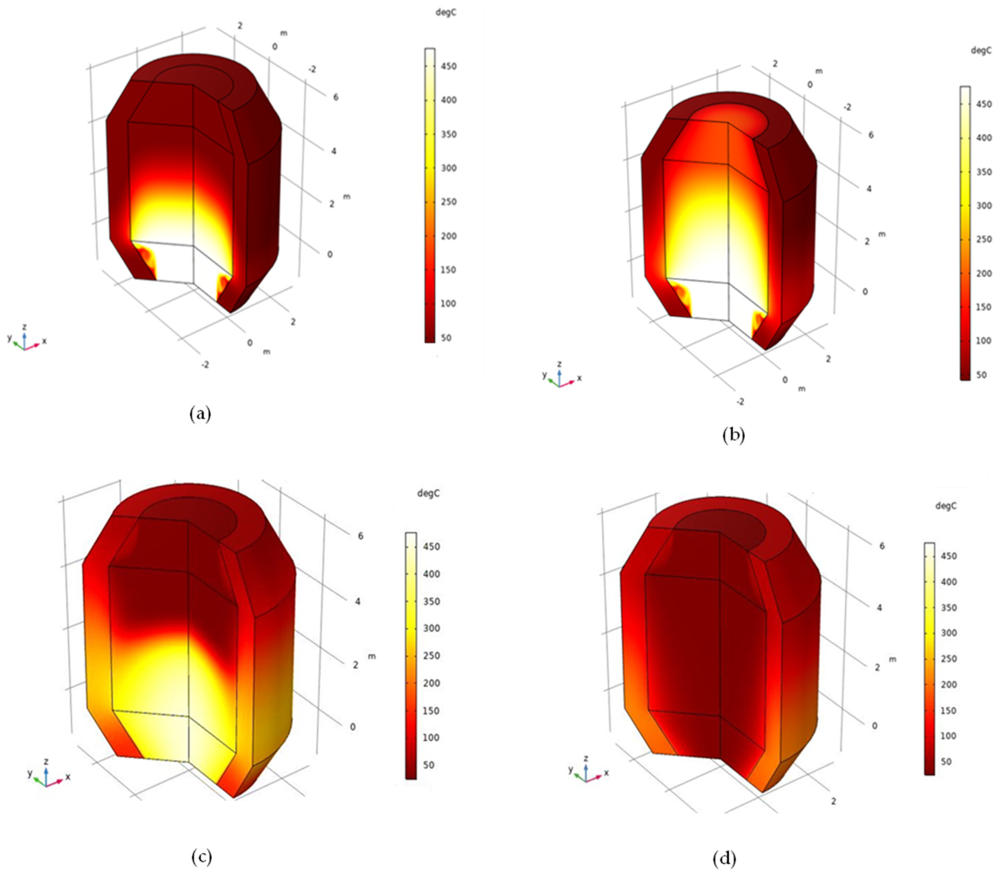
3.2. Hot Storage Charging Cycle

In this section, the hot storage charging cycle has been studied and analyzed over 8 h of charging. The temperature distribution along the z-axis (packed bed height) during the hot storage charging cycle is shown in Figure 6a. Figure 6b shows the capacity factor (CF) of hot storage charging over 6 h.
Figure 6b shows that the capacity factor (CF) of the hot storage tank increases rapidly during the first 3 h of the charging cycle at an almost constant rate, reaching around 90% of its full capacity after 3.5 h. After this, the rate of charging gradually decreases. The reduced rate of heating can be seen in Figure 6a, where the HTF exiting the storage cylinder is around 25 °C.
During the initial charging stages, the heat transfer rate is high due to the significant thermal difference between the HTF and the storage medium. As the charging process continues, the thermal energy is absorbed by the storage medium, resulting in a reduction of the thermal difference between the storage medium and the HTF, which leads to a reduction in the heat transfer rate to the storage medium. As a result, the rate of increase in the storage capacity shows a reduction after the three hours of charging. This reduction continues as the CF increases and the storage becomes fuller.
Figure 7 illustrates the relation between both the energy stored and the power during the 6 h of charging. As the charging time increases, the amount of energy stored initially increases proportionally, and then after four hours, the rate of increase reduces gradually towards zero. Conversely, the total thermal power is initially approximately constant before decreasing as the charging time increases and the storage becomes more charged. Within the first four hours of charging, over 90% of the total energy capacity is stored.

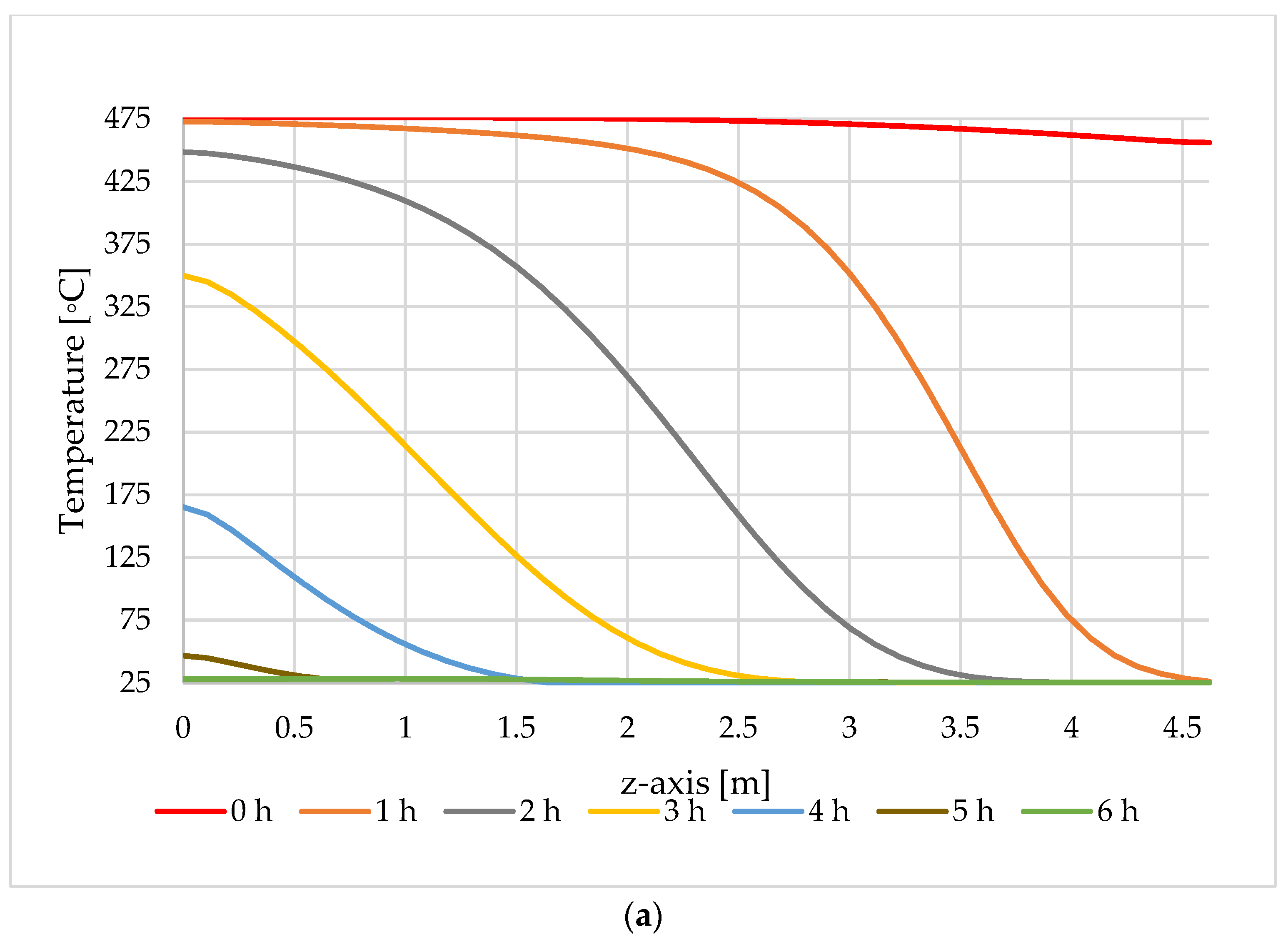
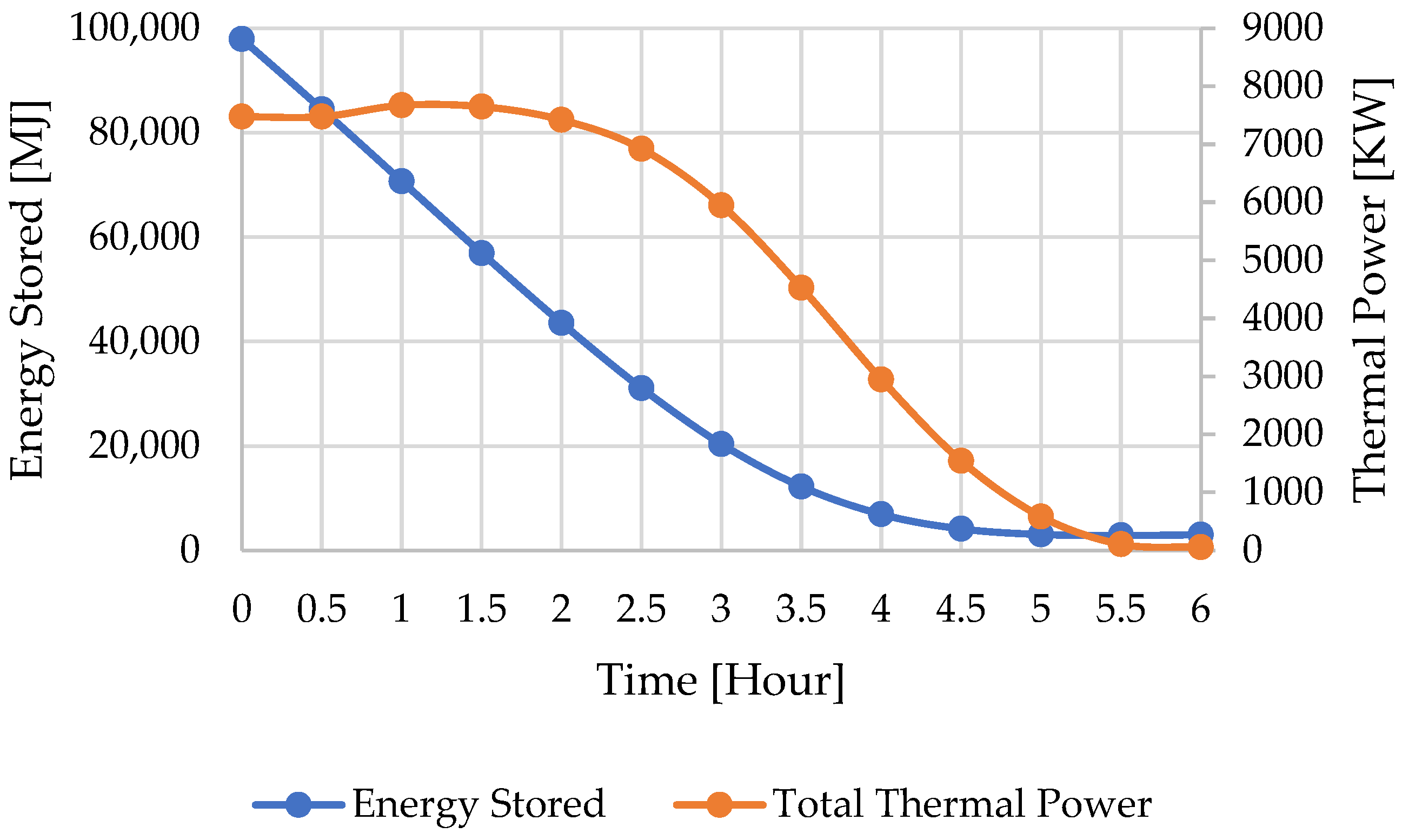
3.3. Hot Storage Discharging Cycle

The hot storage discharging cycle has been studied and analyzed in this section, starting from the conditions at the end of charging, represented by the light green line in Figure 8a. The temperature distribution along the z-axis during the hot storage discharging cycle is shown in Figure 8a. Furthermore, Figure 8b shows the capacity factor (CF) of hot storage discharging over the first 6 h.
Figure 8a shows that the temperature distribution decreases as the discharging time increases during the first 6 h of discharging. In Figure 8b, the capacity factor (CF) decreases as the discharging time increases. This is approximately linear for the first three hours, with approximately 88% of the stored energy being removed from the hot reservoir after 3.5 h of discharging. Subsequently, the discharging rate slows down as the storage tank approaches empty at the end of the discharging period.
This is further illustrated in Figure 9, which shows the relationship between total energy and thermal power over the 6 h of discharging.

3.4. Temperature Profile

The temperature profile inside the packed bed and the storage tank is shown in Figure 10 at times of 2 h and 4 h during the charging process and 2 h and 4 h during the discharging process.
While the temperature profile is relatively constant through the central section of the packed bed, it is seen to change more rapidly close to the insulating wall. There is also a time lag between the heating and cooling of the packed bed and the wall of the tank. After 2 h of charging (Figure 10a), the temperature of the packed bed has reached the temperature of the HTF over approximately the first 1 m of the packed bed, as shown in Figure 6a. However, the tank walls in this region only show a small temperature change. After 4 h of charging (Figure 10b), the temperature of the bottom 1 m of the tank wall has increased from the uncharged state but is still significantly lower than that of the packed bed temperature in this region. Indeed, the temperature of this region of the wall continues to increase into the discharging phase, and the temperature is seen to be higher in Figure 10c after two hours of discharge. We also see in Figure 10c that, in the upper half of the tank, the wall temperature is higher than that of the packed bed, where there is again a lag between the reduction of temperature in the packed bed and the wall. This is also evident in Figure 10d after 4 h of discharge, where the wall is at a higher temperature than the packed bed. This means that, during discharge, the packed bed experiences a loss of energy to the HTF, but also, to a lesser extent, a loss of energy to the walls in regions where the walls are cooler and an increase in energy where the walls are warmer. This secondary transfer of heat to and from the walls can be seen in Figure 9, where the thermal power shows a small increase during the first 1.5 h of charging, rather than maintaining a constant value. It also explains why the energy stored and the CF are not zero in Figure 9 and Figure 8, respectively, despite the temperature at the axis being 25 °C in Figure 8.

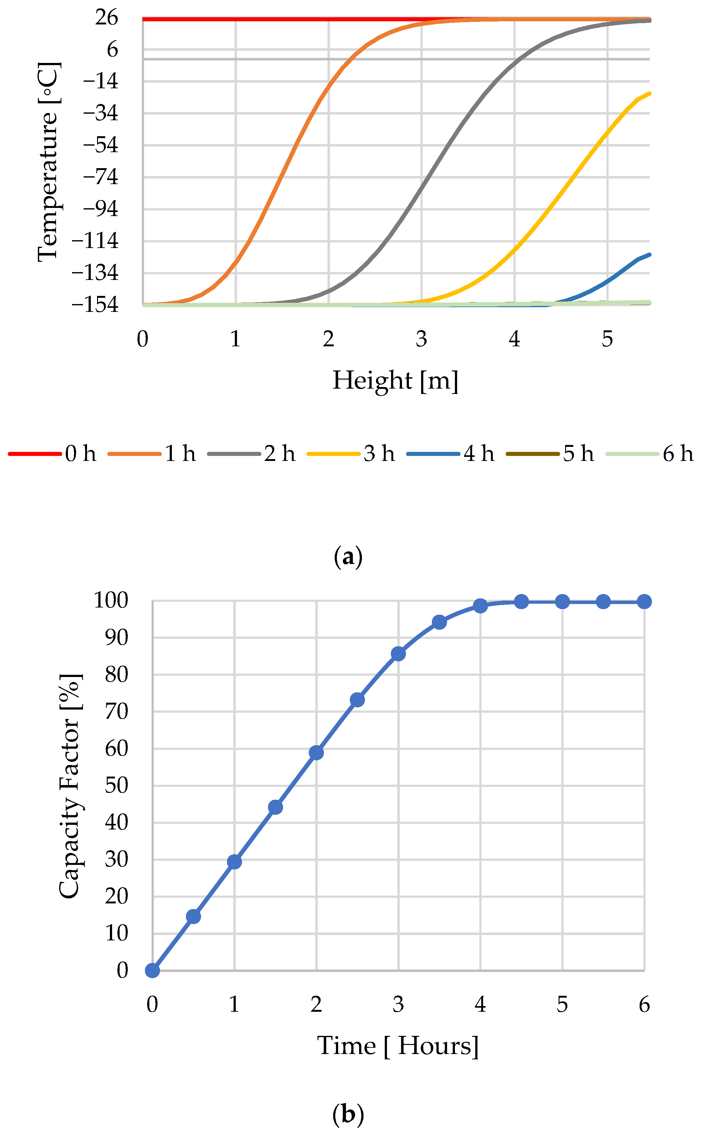
3.5. Cold Storage Charging Cycle

Similar to the hot storage in the previous section, the cold storage charging cycle has been studied and analysed over a 6 h charging period. Accordingly, the cold storage thermal performance analysis has been conducted to evaluate the cold-packed bed during the charging process over the first 6 h of the charging period. Figure 11a shows the temperature profile during the charge operation.
From Figure 11a, we see that, during the first 3 h, the introduced heat is almost entirely transferred to the solid storage material. However, the variation of the outlet fluid temperature is observed for the following four hours of charge operation up to values close to the cold fluid inlet temperature (−154 °C) after 6 h. From this time, as the overall temperature of the solid storage material is near the minimum storage temperature and the initial temperature of the air, further energy transfer is negligible.
Figure 11b shows the charging capacity of the cold storage during the first 6 h of charging. The cold storage tank’s CF increases in the initial three hours of the charging cycle, reaching 86% of its total capacity. The cold storage reaches an efficiency of 98.6% by the end of the fourth hour of charging. After that, it experiences a very slow increase in storage efficiency, reaching 99.97% after 6 h.

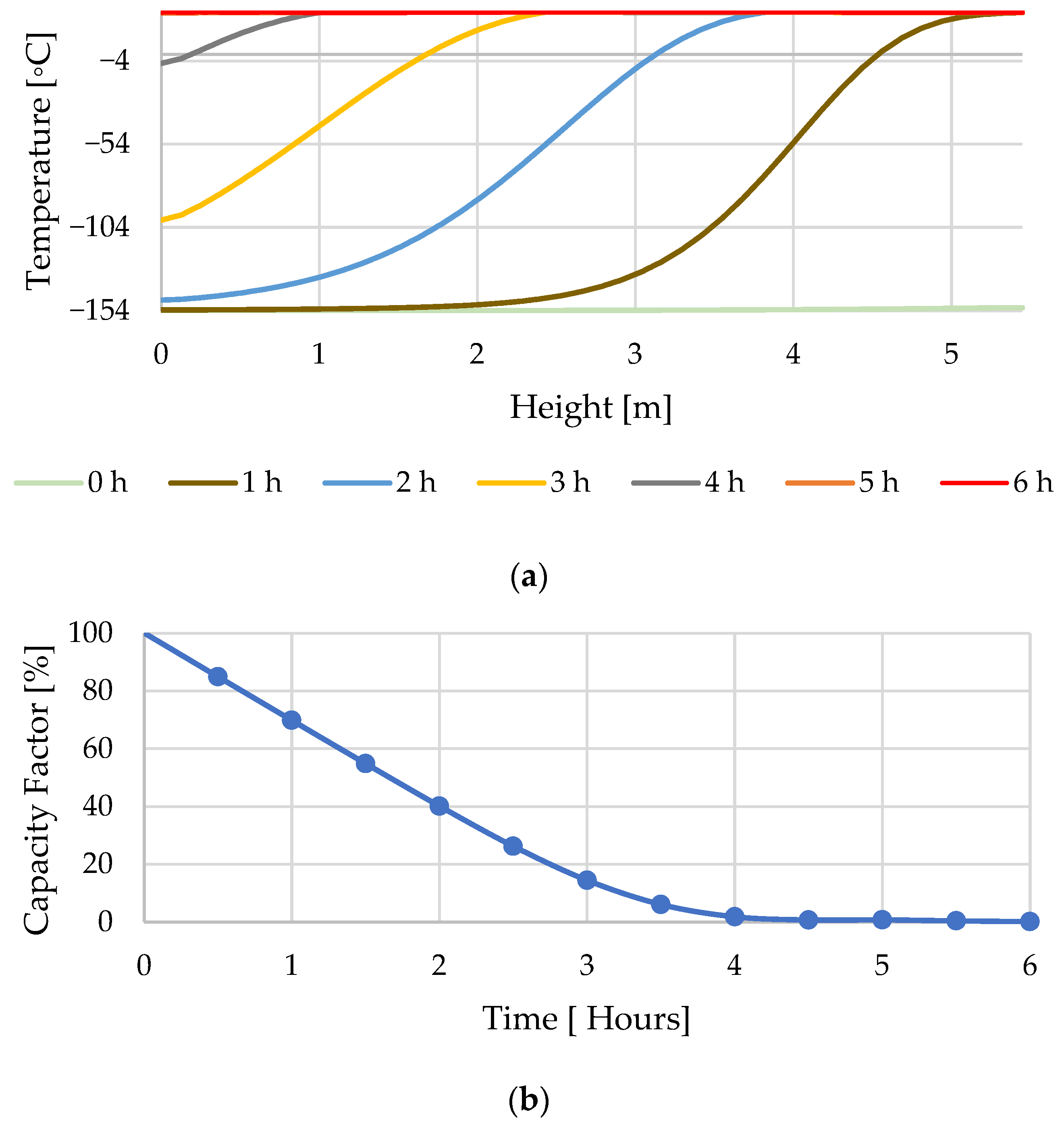
3.6. Cold Storage Discharging Cycle

Similarly, the cold storage tank has been studied and analyzed over 6 h of discharging from the last point of charging, represented by the green line in Figure 11a.
Figure 12a shows the temperature distribution of the cold storage tank at the first 6 h of discharging along the z-axis, while Figure 12b illustrates the discharging capacity factor over the same period of discharge.
The result shows a similar behavior to that observed for the hot storage, with the charging occurring at an approximately constant rate for the first three hours before reducing steadily towards zero. The shorter charge time, compared to the hot storage tank, is affected by the different dimensions of the cold storage tank and, more importantly, by the smaller temperature difference between the charging and discharging temperatures, as shown in Table 1.

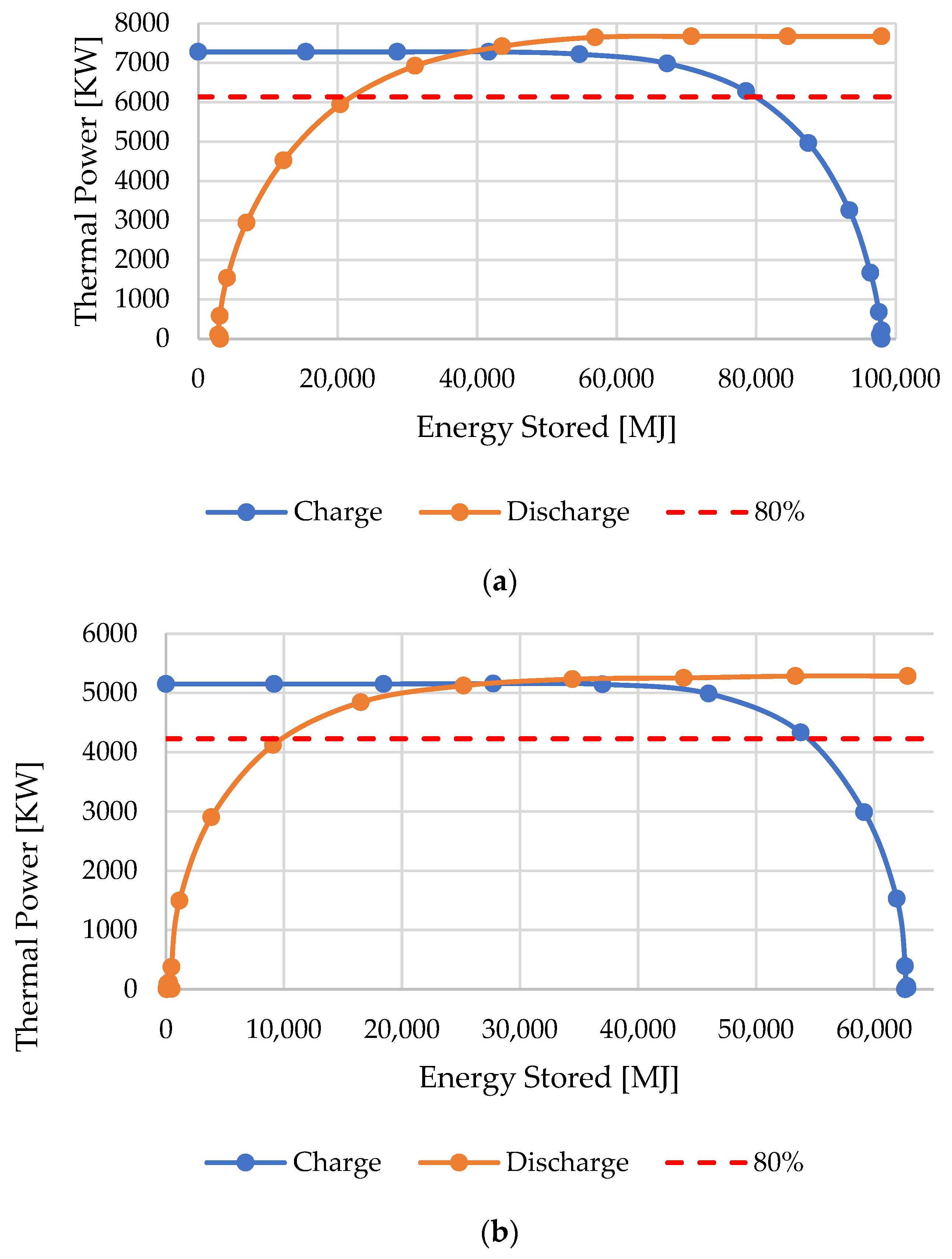
3.7. The Packed-Bed Operation Range

When observing the charging and discharging of both the hot and cold storage tanks, it is evident that the charging is most rapid during the initial charging period when the total energy stored is low. These would appear to be the conditions to achieve maximum performance for the storage tank. However, during discharge, the discharge rate is lowest when the level of energy stored is low. In particular, removing the final 10–20% of capacity takes a significant amount of time, and during this time, the rate of energy transfer is low. Consequently, emptying the storage completely, in order to use the rapid charge rate observed when the charge level is low, may not be the best manner to operate the system. Similarly, the discharge rate is high when the charge level is also high. However, achieving a full charge involved a period of charging over several hours at a low rate. It is, therefore, beneficial to consider the optimal operating process for the packed-bed storage.
Figure 13a and 13b show how the thermal power is related to the energy stored for the hot and cold storage, respectively.
The red horizontal line in Figure 13a,b shows the level of 80% maximum power input/output. The optimal operating range for the packed bed is identified as the conditions where the operating power is within 80% of the maximum, which is characterized by the hot storage operating with a charge in the range 20,000 MJ–80,000 MJ and the cold storage operating in the range 10,000 MJ–54,000 MJ, based on Figure 13a and 13b, respectively. This is approximately 20% and 80% of the full charge for both the hot and cold storage tanks. Operating between these limits would give a good level of performance for both the hot and the cold tank. Based on this, a general recommendation is made that packed-bed storage systems should be operated within this range, corresponding to 20–80% of the full charge.
The results shown in Figure 13 display a level of symmetry regarding the mid-energy value. However, they are not perfectly symmetric. This is due to the different initial conditions at the start of the charge and discharge phases. The initial conditions for the charging phase had the whole system, including the walls, at 25 °C. The initial conditions for the discharge phase corresponded to the conditions at the end of the charge phase. For the hot storage, this corresponded to 476 °C through the majority of the packed bed and HTF, with a slightly lower temperature in the upper region, due to the storage not being completely charged. The temperature of the insulated walls also increases during the charging phase, but the temperature in the walls lags that of the main body of the packed bed, as is evident in Figure 9. The same applied to the cold storage tank with respect to cooling to −154 °C. One effect of these different initial conditions is the peak power in Figure 6 (charging) occurring at the start of the charging phase, while in Figure 9 (discharging), it occurs sometime later. This was explained in Figure 9 by the heat transfer between the walls and the HTF/packed-bed system. This leads to a level of non-symmetry in Figure 13. Additionally, it is also clear that there is a difference between the maximum power rates for charging and discharging in Figure 13, again due to the different initial conditions. Despite these differences, the approximate symmetry in Figure 13 suggests that the performance of the storage system is not highly influenced by the initial conditions, and so, the operating ranges identified in this study should apply regardless of the state of charge at the beginning of the charging or discharging phase.

4. Conclusions

The packed-bed storage technology is considered one of the most promising technologies for the storage of thermal energy due to numerous advantages, including the fact that it is environmentally friendly and economical for large-scale and industrial applications. An optimal packed bed (hot and cold storage) was evaluated during 6 h of charging and 6 h of discharging. The analysis has been conducted based on parameters from a previous optimization study [9], including porosity (0.2), particle diameters (4 mm) for porous media, air for the heat transfer fluid, magnesia for storage media, mass flow rate (13.7 kg/s), and aspect ratio (1).
Two hot and cold TES-packed beds have been assessed during the charging and discharging cycles in order to evaluate their performance. Different methods have been applied to evaluate the packed bed’s thermal performance during the charging and discharging process, such as the packed bed’s capacity factor (CF) and the thermal power, in order to understand their performance and draw recommendations for their operation.
Based on the results of the simulations presented here, it is suggested that both the hot and cold storage systems be operated between 20 and 80% of the full charge to maximize their performance.
We note that the results presented here, and the conclusions drawn from them, are based on simulations for effectively a full charge and a full discharge cycle. Further work will focus on evaluating the performance over different charge–discharge cycles, which could arise, for example, for an intermittent solar heat source. Additionally, heat losses and thermal front dispersion, which will occur over extended storage periods, have not been considered here and will have a negative effect on the storage efficiency. We also note that this work has focused on the packed bed systems in isolation. Within a PTES system, as shown in Figure 2, the storage systems are coupled with a heat pump/heat engine, and the efficiency of the PTES system will drop off as the temperature of the cold discharge increases and the hot discharge decreases.
Figure 8 and Figure 12 show that the discharge temperature changes significantly within 20–80% of the full charge range and indicate that there will be a trade-off between the performance and operation of the packed-bed system and the round-trip efficiency of a PTES system.

Future Work and Limitations

Future work should investigate the effects of these heat losses over both a shorter and a longer storage period and look at the effects of varying the maximum and minimum operating temperatures. This would be more realistic to the input that would be experienced from, for example, an intermittent renewable energy source. It would be interesting to investigate whether this affected the optimal operating range identified here. A key limitation of this work is that the tanks were assumed to be perfectly insulated, and heat losses to the environment were not considered. While this is appropriate when the storage is being constantly charged and discharged, it will not account for losses that occur, particularly when storage occurs over a longer time period. It would also be interesting to investigate the long-term storage capabilities.

Author Contributions

Conceptualization, J.R. and J.M.B.; methodology, A.M.R., J.R. and J.M.B.; software, A.M.R.; validation, A.M.R.; formal analysis, A.M.R.; investigation, A.M.R., J.R. and J.M.B.; resources, J.R. and J.M.B.; data curation, A.M.R.; writing—original draft preparation, A.M.R.; writing— review and editing, A.M.R., J.R. and J.M.B.; visualization, A.M.R.; supervision, J.R. and J.M.B.; project administration, J.R. and J.M.B. All authors have read and agreed to the published version of the manuscript.

Funding

This research received no external funding.

Data Availability Statement

Datasets are available upon request from the authors.

Conflicts of Interest

The authors declare no conflicts of interest.

Nomenclature

AbbreviationRoman symbols
AAAdvanced-AdiabaticCFCapacity factor
CAESCompressed-Air Energy StoragecfCoefficient of friction
HTFHeat Transfer FluidCfForcheimer parameter
LAESLiquid-Air Energy StorageCpHeat Capacity
PBSSPacked-Bed Storage SystemDPacked Bed Diameter
PHESPumped Heat Energy StoragedpParticle diameter
PTESPumped Thermal Energy StorageEstoredEnergy Stored
RTERound Trip EfficiencygAcceleration of gravity
TESThermal Energy StorageHPacked-Bed height
Greek symbolsKThermal conductivity
αThermal diffusivitylLength scale
ɛPorosity (void fraction) m ˙ Mass flowrate
ɳEfficiencyPOperating Pressure
θVolume fractionPTHThermal Power
μ porous media viscosityqConductive heat fluxes
ρDensityQHeat sources
τViscous stress tensorqsfInterstitial convective heat transfer coefficient
SubscriptsSSeebeck coefficient
chChargingtTime
disDischargingTTemperature
fFluiduSuperficial velocity
HTHeat TransfervInterstitial velocity
iInitial Q v d Viscous dissipation
sSolid Q t e d Thermoelastic damping
THThermal

References

  1. White, A.; Parks, G.; Markides, C.N. Thermodynamic analysis of pumped thermal electricity storage. Appl. Therm. Eng. 2013, 53, 291–298. [Google Scholar] [CrossRef]
  2. Rabi, A.M.; Radulovic, J.; Buick, J.M. Pumped Thermal Energy Storage Technology (PTES): Review. Thermo 2023, 3, 396–411. [Google Scholar] [CrossRef]
  3. McTigue, J.D.; White, A.J.; Markides, C.N. Parametric studies and optimisation of pumped thermal electricity storage. Appl. Energy 2015, 137, 800–811. [Google Scholar] [CrossRef]
  4. Mercangöz, M.; Hemrle, J.; Kaufmann, L.; Z’gRaggen, A.; Ohler, C. Electrothermal energy storage with transcritical CO2 cycles. Energy 2012, 45, 407–415. [Google Scholar] [CrossRef]
  5. Elsihy, E.S.; Wang, X.; Xu, C.; Du, X. Numerical investigation on simultaneous charging and discharging process of molten-salt packed-bed thermocline storage tank employing in CSP plants. Renew. Energy 2021, 172, 1417–1432. [Google Scholar] [CrossRef]
  6. Barbour, E.; Mignard, D.; Ding, Y.; Li, Y. Adiabatic Compressed Air Energy Storage with packed bed thermal energy storage. Appl. Energy 2015, 155, 804–815. [Google Scholar] [CrossRef]
  7. Geissbühler, L.; Becattini, V.; Zanganeh, G.; Zavattoni, S.; Barbato, M.; Haselbacher, A.; Steinfeld, A. Pilot-scale demonstration of advanced adiabatic compressed air energy storage, Part 1: Plant description and tests with sensible thermal-energy storage. J. Energy Storage 2018, 17, 129–139. [Google Scholar] [CrossRef]
  8. Alva, G.; Liu, L.; Huang, X.; Fang, G. Thermal energy storage materials and systems for solar energy applications. Renew. Sustain. Energy Rev. 2017, 68, 693–706. [Google Scholar] [CrossRef]
  9. Rabi’, A.M.; Radulovic, J.; Buick, J.M. Packed Bed Thermal Energy Storage System: Parametric Study. Thermo 2024, 4, 295–314. [Google Scholar] [CrossRef]
  10. Alva, G.; Lin, Y.; Fang, G. An overview of thermal energy storage systems. Energy 2018, 144, 341–378. [Google Scholar] [CrossRef]
  11. Gil, A.; Medrano, M.; Martorell, I.; Lázaro, A.; Dolado, P.; Zalba, B.; Cabeza, L.F. State of the art on high temperature thermal energy storage for power generation. Part 1—Concepts, materials and modellization. Renew. Sustain. Energy Rev. 2010, 14, 31–55. [Google Scholar] [CrossRef]
  12. Medrano, M.; Gil, A.; Martorell, I.; Potau, X.; Cabeza, L.F. State of the art on high-temperature thermal energy storage for power generation. Part 2—Case studies. Renew. Sustain. Energy Rev. 2010, 14, 56–72. [Google Scholar] [CrossRef]
  13. Balakrishnan, A.R.; Pei, D.C.T. Heat Transfer in Gas-Solid Packed Bed Systems. 2. The Conduction Mode. Ind. Eng. Chem. Process Des. Dev. 1979, 18, 40–46. [Google Scholar] [CrossRef]
  14. Almendros-Ibáñez, J.; Fernández-Torrijos, M.; Díaz-Heras, M.; Belmonte, J.; Sobrino, C. A review of solar thermal energy storage in beds of particles: Packed and fluidized beds. Sol. Energy 2019, 192, 193–237. [Google Scholar] [CrossRef]
  15. Zanganeh, G.; Pedretti, A.; Haselbacher, A.; Steinfeld, A. Design of packed bed thermal energy storage systems for high-temperature industrial process heat. Appl. Energy 2015, 137, 812–822. [Google Scholar] [CrossRef]
  16. de Gracia, A.; Cabeza, L.F. Numerical simulation of a PCM packed bed system: A review. Renew. Sustain. Energy Rev. 2017, 69, 1055–1063. [Google Scholar] [CrossRef]
  17. Elouali, A.; Kousksou, T.; El Rhafiki, T.; Hamdaoui, S.; Mahdaoui, M.; Allouhi, A.; Zeraouli, Y. Physical models for packed bed: Sensible heat storage systems. J. Energy Storage 2019, 23, 69–78. [Google Scholar] [CrossRef]
  18. Sanderson, T.; Cunningham, G. Performance and efficient design of packed bed thermal storage systems. Part 1. Appl. Energy 1995, 50, 119–132. [Google Scholar] [CrossRef]
  19. Ge, Y.; Zhao, Y.; Zhao, C. Transient simulation and thermodynamic analysis of pumped thermal electricity storage based on packed-bed latent heat/cold stores. Renew. Energy 2021, 174, 939–951. [Google Scholar] [CrossRef]
  20. Gallo, A.B.; Simõões-Moreira, J.R.; Costa, H.K.M.; Santos, M.M.; Moutinho dos Santos, E.M. Energy storage in the energy transition context: A technology review. Renew. Sustain. Energy Rev. 2016, 65, 800–822. [Google Scholar] [CrossRef]
  21. Petrollese, M.; Cascetta, M.; Tola, V.; Cocco, D.; Cau, G. Pumped thermal energy storage systems integrated with a concentrating solar power section: Conceptual design and performance evaluation. Energy 2022, 247, 123516. [Google Scholar] [CrossRef]
  22. Mazzucco, G.; Xotta, G.; Salomoni, V.; Giannuzzi, M.; Maiorana, C. Solid thermal storage with PCM materials. Numerical investigations. Appl. Therm. Eng. 2017, 124, 545–559. [Google Scholar] [CrossRef]
  23. Benato, A.; Stoppato, A. Pumped Thermal Electricity Storage: A technology overview. Therm. Sci. Eng. Prog. 2018, 6, 301–315. [Google Scholar] [CrossRef]
  24. Farres-Antunez, P.; McTigue, J.D.; White, A.J. A pumped thermal energy storage cycle with capacity for concentrated solar power integration. In Proceedings of the 2019 Offshore Energy and Storage Summit (OSES), Brest, France, 10–12 July 2019; pp. 1–10. [Google Scholar]
  25. Singh, H.; Saini, R.; Saini, J. A review on packed bed solar energy storage systems. Renew. Sustain. Energy Rev. 2010, 14, 1059–1069. [Google Scholar] [CrossRef]
  26. Esence, T.; Bruch, A.; Molina, S.; Stutz, B.; Fourmigué, J.-F. A review on experience feedback and numerical modeling of packed-bed thermal energy storage systems. Sol. Energy 2017, 153, 628–654. [Google Scholar] [CrossRef]
  27. Saez, A.E.; McCoy, B.J. Dynamic response of a packed bed thermal storage system—A model for solar air heating. Sol. Energy 1982, 29, 201–206. [Google Scholar] [CrossRef]
  28. Beasleyt, D.E.; Clark, J.A. Transient response of a packed for thermal energy storage bed. Int. J. Heat Mass Transf. 1984, 27, 1659–1669. [Google Scholar] [CrossRef]
  29. Singh, H.; Saini, R.; Saini, J. Performance of a packed bed solar energy storage system having large sized elements with low void fraction. Sol. Energy 2013, 87, 22–34. [Google Scholar] [CrossRef]
  30. Anderson, R.; Bates, L.; Johnson, E.; Morris, J.F. Packed bed thermal energy storage: A simplified experimentally validated model. J. Energy Storage 2015, 4, 14–23. [Google Scholar] [CrossRef]
  31. Mctigue, J.D.; White, A.J. A comparison of radial-flow and axial-flow packed beds for thermal energy storage. Appl. Energy 2018, 227, 533–541. [Google Scholar] [CrossRef]
  32. Peng, H.; Shan, X.; Yang, Y.; Ling, X. A study on performance of a liquid air energy storage system with packed bed units. Appl. Energy 2018, 211, 126–135. [Google Scholar] [CrossRef]
  33. Hänchen, M.; Brückner, S.; Steinfeld, A. High-temperature thermal storage using a packed bed of rocks—Heat transfer analysis and experimental validation. Appl. Therm. Eng. 2011, 31, 1798–1806. [Google Scholar] [CrossRef]
  34. Laubscher, H.F.; von Backström, T.W.; Dinter, F. Developing a cost effective rock bed thermal energy storage system: Design and modelling. AIP Conf. Proc. 2017, 1850, 080015. [Google Scholar] [CrossRef]
  35. Zanganeh, G.; Pedretti, A.; Zavattoni, S.; Barbato, M.; Steinfeld, A. Packed-bed thermal storage for concentrated solar power—Pilot-scale demonstration and industrial-scale design. Sol. Energy 2012, 86, 3084–3098. [Google Scholar] [CrossRef]
  36. Zanganeh, G.; Pedretti, A.; Zavattoni, S.; Barbato, M.; Haselbacher, A.; Steinfeld, A. Design of a 100 MWhth Packed-bed Thermal Energy Storage. Energy Procedia 2014, 49, 1071–1077. [Google Scholar] [CrossRef]
  37. Marti, J.; Geissbühler, L.; Becattini, V.; Haselbacher, A.; Steinfeld, A. Constrained multi-objective optimization of thermocline packed-bed thermal-energy storage. Appl. Energy 2018, 216, 694–708. [Google Scholar] [CrossRef]
  38. Yang, B.; Wang, Y.; Bai, F.; Wang, Z. Experimental and numerical investigation of a packed-bed thermal energy storage device Capital cost expenditure of high temperature latent and sensible thermal energy storage systems Experimental and Numerical Investigation of a Packed-bed Thermal Energy. AIP Conf. Proc. 2017, 1850, 080027. [Google Scholar] [CrossRef]
  39. Ortega-Fernández, I.; Zavattoni, S.A.; Rodríguez-Aseguinolaza, J.; D’AGuanno, B.; Barbato, M.C. Analysis of an integrated packed bed thermal energy storage system for heat recovery in compressed air energy storage technology. Appl. Energy 2017, 205, 280–293. [Google Scholar] [CrossRef]
  40. Schlipf, D.; Faust, E.; Schneider, G.; Maier, H. First operational results of a high temperature energy storage with packed bed and integration potential in CSP plants. AIP Conf. Proc. 2017, 1850, 080024. [Google Scholar] [CrossRef]
  41. White, A.J.; McTigue, J.D.; Markides, C.N. Analysis and optimisation of packed-bed thermal reservoirs for electricity storage applications. Proc. Inst. Mech. Eng. Part A J. Power Energy 2016, 230, 739–754. [Google Scholar] [CrossRef]
  42. Meier, A.; Winkler, C.; Wuillemin, D. Experiment for modelling high temperature rock bed storage. Sol. Energy Mater. 1991, 24, 255–264. [Google Scholar] [CrossRef]
  43. Xu, C.; Wang, Z.; He, Y.; Li, X.; Bai, F. Sensitivity analysis of the numerical study on the thermal performance of a packed-bed molten salt thermocline thermal storage system. Appl. Energy 2012, 92, 65–75. [Google Scholar] [CrossRef]
  44. COMSOL Multiphysics. Porous Media Flow Module. Available online: https://doc.comsol.com/5.6/doc/com.comsol.help.porous/PorousMediaFlowModuleUsersGuide.pdf (accessed on 17 July 2025).
  45. Nandi, B.R.; Bandyopadhyay, S.; Banerjee, R. Numerical modeling and analysis of dual medium thermocline thermal energy storage. J. Energy Storage 2018, 16, 218–230. [Google Scholar] [CrossRef]
  46. Bennett, J.P. High-Temperature Properties of Magnesia-Refractory Brick Treated With Oxide and Salt Solutions; United States Department of the Interior, Bureau of Mines: Washington, DC, USA, 1985. [Google Scholar]
  47. Rao, L.H.; Dirbude, S. Numerical modelling and optimization of packed-bed thermal-energy storage system. J. Phys. Conf. Ser. 2022, 2178, 012003. [Google Scholar] [CrossRef]
Figure 1. Packed-bed main components [9].
Thermo 05 00024 g001
Figure 2. The conventional layout of PTES and its main components [2].
Thermo 05 00024 g002
Figure 3. Schematic of the hot reservoir storage tank.
Thermo 05 00024 g003
Figure 4. The effect of the mesh size on the temperature difference at different heights during charging.
Thermo 05 00024 g004
Figure 5. Comparison of the COMSOL results with the experimental data of Meier et al. [42].
Thermo 05 00024 g005
Figure 6. Hot storage charging cycle over the first 6 h (a) The temperature profile along the z-axis, (b) hot storage capacity factor (CF).
Thermo 05 00024 g006
Figure 7. Total energy stored and thermal power during the charging period.
Thermo 05 00024 g007
Figure 8. Hot storage discharging cycle over 6 h (a) The temperature profile along the z-axis, (b) hot storage capacity factor.
Thermo 05 00024 g008aThermo 05 00024 g008b
Figure 9. The hot storage total energy stored against the thermal power over 6 h of discharging.
Thermo 05 00024 g009
Figure 10. The temperature distribution along the storage tank at different charging and discharging times: (a) Charging after 2 h, (b) Charging after 4 h, (c) Discharging after 2 h, and (d) Discharging after 4 h.
Thermo 05 00024 g010
Figure 11. Cold storage charging cycle over 6 h. (a) The temperature profile along the z-axis, (b) cold storage capacity factor.
Thermo 05 00024 g011
Figure 12. Cold storage discharging cycle over 6 h. (a) The temperature distribution along the z-axis; (b) the discharging capacity factor.
Thermo 05 00024 g012
Figure 13. The operating power at different storage levels for (a) the hot storage and (b) the cold storage.
Thermo 05 00024 g013
Table 1. An evaluation of the most promising TES technologies: CAES, PHES, and PTES systems.
TES SystemCAESPHESPTES
Cost [USD/kWh]2.55–10025–250
RTE [%]50–7060–8040–70
Energy Density [kWh/m3]101.450
Table 2. A comparison of different PBSS systems utilizing various filling materials.
Packed Bed Storage MediaFiller Cost [$/Ton]AdvantagesLimitations
AL2O31500Good thermal shock resistance and high temperature stability.Material cost and processing are expensive and heavy.
Concrete500Good availability, easy to shape, and moderate costThermal cracking risk and degradation at higher temperatures (>400 °C).
Natural rocks200Widely available and very low costPotential cracking and limited mechanical strength at very high temperatures.
Magnesia bricks1000Corrosion-resistant and excellent high-temperature stabilityManufacturing complexity and higher cost than natural rock.
Molten Salts1500Fluid simplifies heat transfer; High heat capacity.Relatively expensive; corrosion issues; freezing risk (~220 °C).
Table 3. Mesh type, number of elements, and simulation time.
Mesh
Type
Extremely
Coarse
Extra CoarseCoarserCoarseNormalFineFinerExtra FineExtremely Fine
Number of
elements
37559693317542634437710,57124,68845,622
Simulation time [min]2.04.07.920.237.279.7299.51069.82680.6
Table 4. Hot and cold storage dimensions and operational parameters [41].
Storage TankSymbolUnitValue
PTES (Hot reservoir)
Tank DiameterD[m]4.62
Tank HightH[m]4.62
Charging TemperatureTch[°C]476.00
Discharging TemperatureTdis[°C]25.00
PTES (Cold reservoir)
Tank DiameterD[m]5.45
Tank HightH[m]5.45
Charging TemperatureTch[°C]−154.00
Discharging TemperatureTdis[°C]25.00
Table 5. The optimum design parameter [9].
Design ParameterSymbolUnitValue
Medium particle diameter/sizedp[mm]4
Solid storage material------Magnesia
Void fraction (porosity)ɛ---0.20
Table 6. Thermo-physical and chemical properties of Magnesia packing materials [11,46].
Thermo-Physical Properties
Cp, s [J/kg·K]1150
ρ s [kg/m3]3000
Ks [W/m. K]5.0
Chemical Properties
Magnesium(MgO)[%]89.10
Iron oxide(Fe2O3)[%]1.83
Alumina(AL2O3)[%]0.38
Chromium oxide(Cr2O3)[%]0.42
Silica(SiO2)[%]7.40
Calcia(CaO)[%]0.87
Melting temperature [°C] ~ 1600
Table 7. Experimental parameter of Meier et al. [42].
Storage TankSymbolUnitValue
Tank DiameterDm0.70
Tank HightHm1.93
Charging TemperatureTch°C600
Discharging TemperatureTdis°C27
Particle Diameterdpmm2.00
Mass flow rate m ˙ kg/s1.10
Porosityɛ-0.45
Solid storage material------Rock
Disclaimer/Publisher’s Note: The statements, opinions and data contained in all publications are solely those of the individual author(s) and contributor(s) and not of MDPI and/or the editor(s). MDPI and/or the editor(s) disclaim responsibility for any injury to people or property resulting from any ideas, methods, instructions or products referred to in the content.

